Article

Gob-Side Entry Retained with Soft Roof, Floor, and Seam in Thin Coal Seams: A Case Study

1
State Key Laboratory of Coal Resources and Safe Mining, China University of Mining and Technology, Xuzhou 221116, China
2
Work Safety Key Lab on Prevention and Control of Gas and Roof Disasters for Southern Goal Mines, Hunan Provincial Key Laboratory of Safe Mining Techniques of Coal Mines, Hunan University of Science and Technology, Xiangtan 411201, China
3
School of Resource, Environment and Safety Engineering, Hunan University of Science and Technology, Xiangtan 411201, China
*
Authors to whom correspondence should be addressed.
Sustainability 2020, 12(3), 1197; https://doi.org/10.3390/su12031197
Submission received: 22 November 2019 / Revised: 22 January 2020 / Accepted: 23 January 2020 / Published: 7 February 2020
(This article belongs to the Section Energy Sustainability)

Abstract

:
Gob-side entry retained technology is of great significance to develop coal mining industry sustainably, which can improve the coal recovery rate by mining without the coal pillar. However, scholars and researchers pay little attention to the gob-side entry retained with soft roof, floor, and seam in thin coal seams. In this study, the difficulties and key points of surrounding rock control for gob-side entry retained with soft roof, floor, and seam in thin coal seams were firstly proposed. Secondly, the mechanical model of the interaction between the roadside backfill body and the roof for gob-side entry retained with soft roof, floor, and seam in thin coal seams was established, and the relevant parameters were designed. Finally, the above results were verified by the engineering practice of gob-side entry retained technology and the monitoring of mine pressure on the 1103 working face of the Heilong Coal Mine. Moreover, the effect factors of surrounding rock stability for gob-side entry retained with soft roof, floor, and seam in thin coal seams were discussed using the discrete element method. The results could provide guidance for gob-side entry retained with soft roof, floor, and seam in thin coal seams under similar geological conditions.

1. Introduction

Coal is a precious non-renewable energy. For sustainable utilization of limited coal resources, it is important to increase the coal recovery rate. China has abundant coal resources with large reserves and diversification. The proven recoverable reserves of thin coal seams (TCMs) are about 6 billion tons, accounting for about 20% of the total coal reserves in China. Among them, the gently inclined TCM with a thickness of 0.8~1.3 m account for 73.4%, and the layers of TCMs below medium and hard coal account for 64.59% of the total layers, which have great mining value. However, since the mining roadway of the TCM working face is a mixed coal-rock roadway, the drifting speed is slow with a lot of gangue, which may lead to a strain between mining and drifting. High-efficiency mining technology for TCMs is an important technical way to improve the recovery rate of coal resources and achieve sustainable development of coordinated mining. In order to alleviate the tight situation of mining replacement, it is of great strategic significance to carry out and develop gob-side entry retained (GER) technology. Coal pillar and no-pillar for surrounding rock control are the two mostly used layouts in longwall panel coal mining. GER is beneficial for the sustainable development of the coal mining industry by mining without the coal pillar [1,2,3,4,5] GER maintains the gob boundary roadway behind the working face. The original roadway is retained and used as a roadway adjacent to the working face through effective roadside backfill and road-in support technology (see Figure 1) [6,7,8,9,10].
GER has been widely carried out in many Chinese coal mines due to its advantages [11,12,13,14,15,16]. Many scholars and experts have studied road-in support, roadside backfill body (RBB) construction, backfill materials, and GER surrounding rock stability for GER. Therefore, it has been found that bolt and anchor cable support and rigid U steel support are commonly used as road-in support for GER [17,18,19,20,21,22,23]. Huang [17] developed the concrete-filled steel tubular support for a 1000 m-deep roadway. Chen [18] proposed that high-strength bolt and anchor support owning high pre-stress force, increasing the carrying capacity of surrounding rock, and adapting to large deformation was successfully carried out in GER. Moreover, the road-in support technology should meet the requirement of large deformation of surrounding rock, a long maintenance period, and a large damage range.
For backfill materials, high-water quick-setting materials, concrete, gangue, and other mixed concrete and gangue materials have been used to construct RBBs for GER under different geological and mining conditions [24,25,26,27,28]. RBBs constructed with high-water, quick-setting materials have been employed for GER in thin coal seams (Nantun Coal Mine [29]), middle-thick coal seams (Xinchao Coal Mine [30], Xingwu Coal Mine [31]), and thick coal seams (Liujiazhuang Coal Mine [32], Yuwu Coal Mine [33]). RBBs constructed with gangue have been employed for GER in thin coal seams (Jiangjiawan Coal Mine [34]), middle-thick coal seams (Huayuan Coal Mine [35]), and thick coal seams (Tangkou Coal Mine [36]). Meanwhile, RBBs constructed with concrete have been employed for GER in thin coal seams (Quanshang Coal Mine [37]), middle-thick coal seams (JingangCoal Mine [38]), and thick coal seams (Shangwan Coal Mine [39]). Fan [40] applied the mechanics of materials to calculate the cutting force of RBBs based on the simplified structural mechanical model. Su [41] established the interaction mechanical model between roofing and roadside backfilling of GER in a fully-mechanized longwall with top coal caving to obtain the roof-cutting resistance of RBBs. Zhang [3] derived the equations to calculate the desired support resistance of the gob-side wall. Therefore, roadside support should cut off the main roof and immediate roof, fit the main roof rotation and subsidence, and restrain the separation between the main roof and immediate roof. These research results provide some guidelines and approaches to GER with hard roof. However, few engineering cases for GER with soft roof, floor, and seam in TCMs were reported except some theoretical study or numerical calculation [42]. This paper firstly proposes the structural characteristics of overburden strata for GER with soft roof, floor, and seam in TCMs, analyzes the difficulties in surrounding rock control for GER with soft roof, floor, and seam in TCMs, and presents surrounding rock stability control technology. Secondly, the key parameters (i.e., RBB width, RBB support resistance, water cement ratio of high-water quick-setting materials) are designed. Finally, field practice is carried out at the No. 1103 haulage roadway of the Heilong Coal Mine.

2. Mining Geological Conditions of Tested Roadway

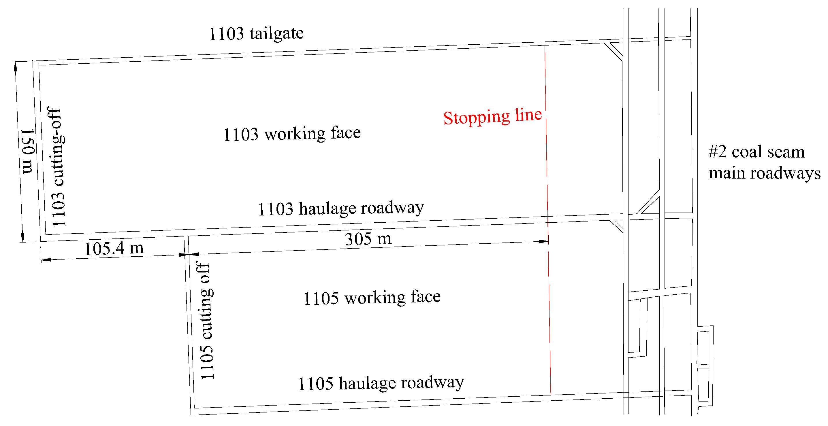
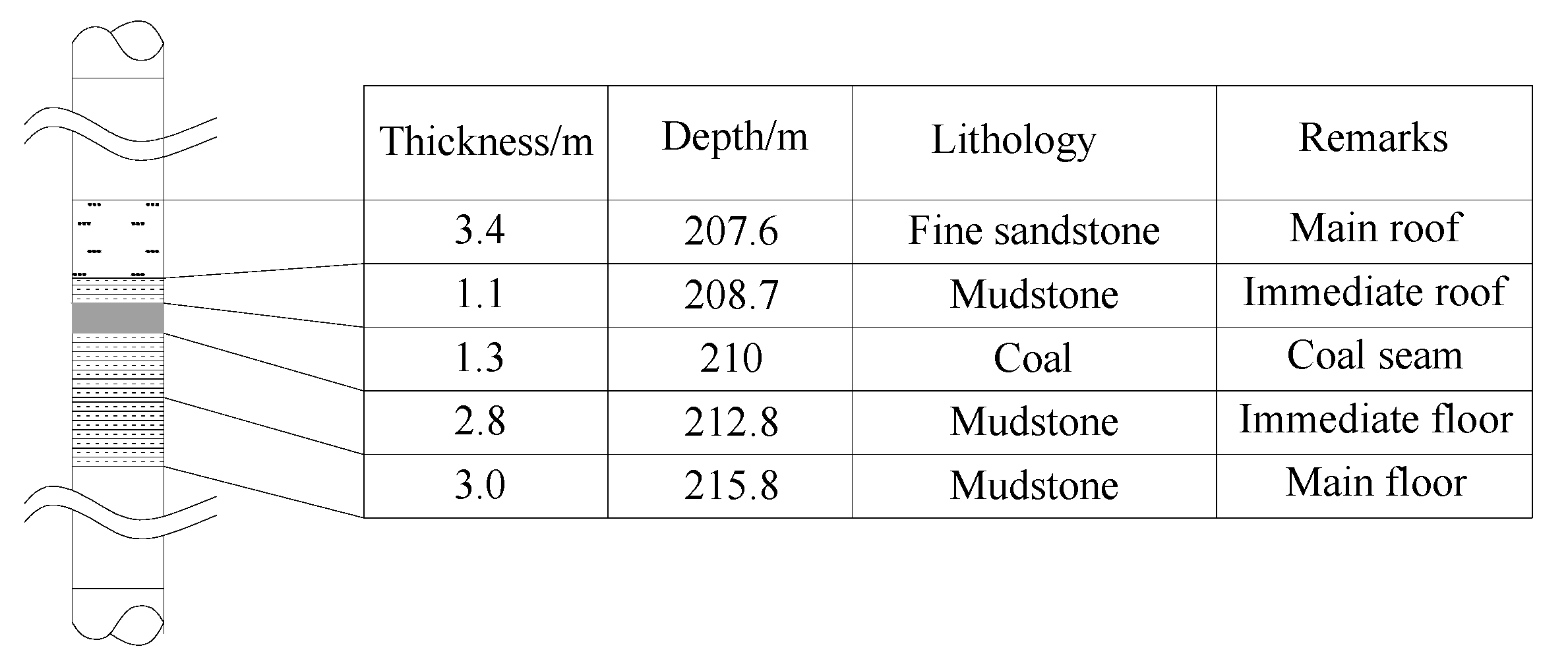
The present analysis was based on the mining conditions of the 1103 working face in the Heilong Coal Mine, located in Linfen City, Shanxi Province of China. The main coal seam mined at the 1103 working face is #2 coal seam dipped 0~20°, of which the average thickness is 1.3 m and the average bury depth is 210 m. Fully-mechanized longwall mining technology is carried out on the 1103 working face. The 1103 working face is adjacent to the 1101 working face (gob), arranged along the coal seam dip. The 1103 working face is a low gassy working face and is 200 m wide (see Figure 2). The immediate roof is mudstone, and the main roof is fine sandstone. Both the immediate floor and the main floor are mudstone. The bore hole columnar section is shown in Figure 3.
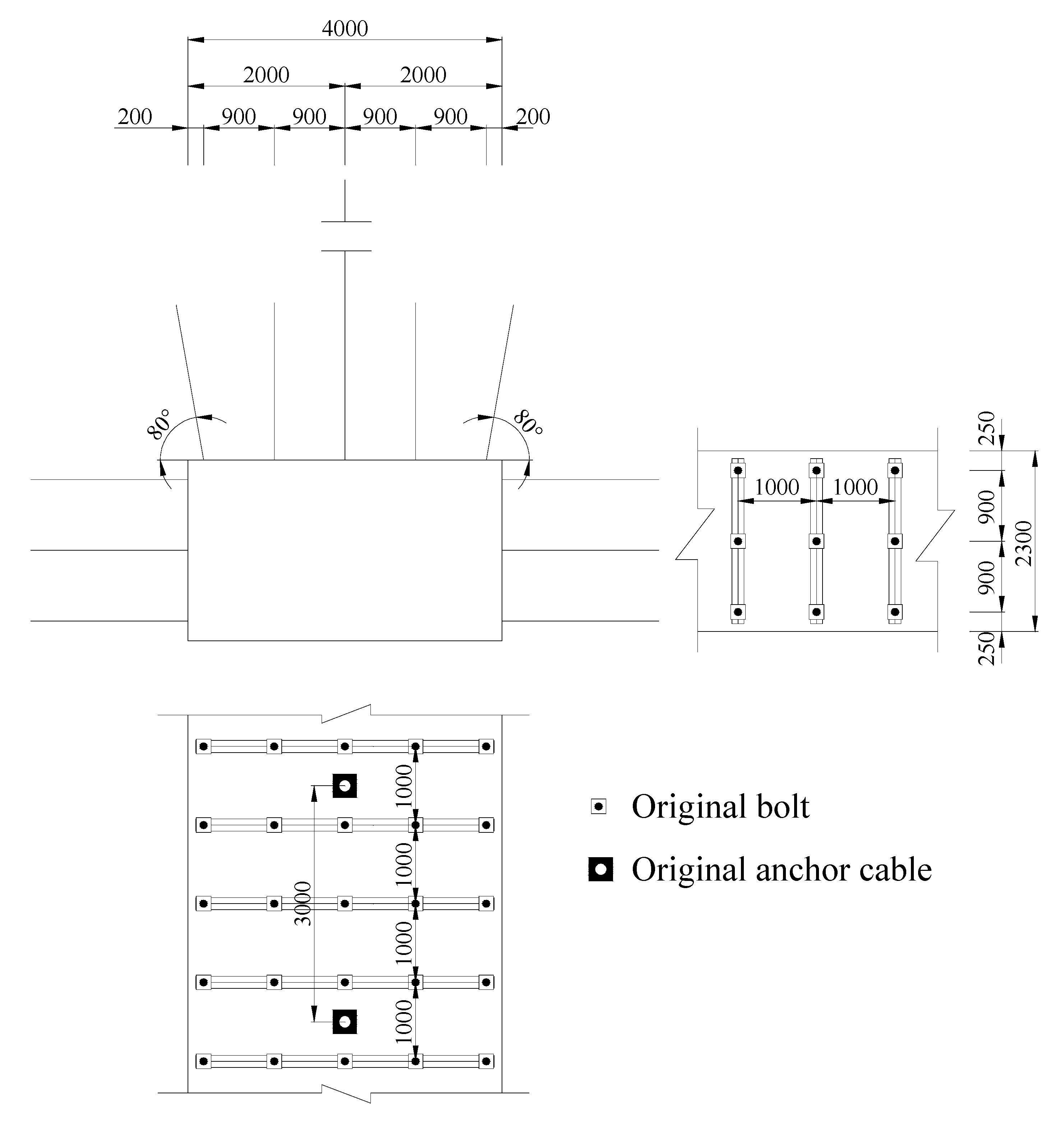
The section of the No. 1103 haulage gateway is a rectangular section, 4.0 m wide and 2.3 m high. The No. 1103 haulage gateway is driven along the roof of the coal seam and is supported by anchor cables and bolts. The detailed support parameters are as follows (see Figure 4):
(1)
The roof was supported by Φ18 mm × 2000 mm bolts, and five rows were set up with the spacing of 900 mm × 1000 mm. The bolts were arranged by a steel ladder beam welded with round steel, 14 mm in diameter and 3800 mm long. The roof was also supported by Φ17.8 mm × 6300 mm anchor cables, and a row was set up with the spacing of 3000 mm along the roadway. The roof was wrapped by a net, which was 4000 mm wide and 1100 mm long.
(2)
The coal rib was supported by Φ18 mm × 2000 mm bolts, and three rows were set up with the spacing of 900 mm × 1000 mm. The bolts were arranged by the steel ladder beam welded with round steel, 14 mm in diameter and 2100 mm long. The coal rib was wrapped by a net, which was 2300 mm wide and 1100 mm long.

3. GER with Soft Roof, Floor, and Seam in TCMs

3.1. Structural Characteristics of Overburden Strata for GER with Soft Roof, Floor and Seam in TCMs

Large deformation of surrounding rock for GER with soft roof, floor, and seam in TCMs is usually associated with the activities of the overlying strata, especially the arc-shaped triangular block activities of the main roof caused by the roof lateral fracture. Therefore, it is necessary to analyze and recognize the surrounding rock structure and activity rules formed by overlying strata for GER with soft roof, floor, and seam in TCMs.
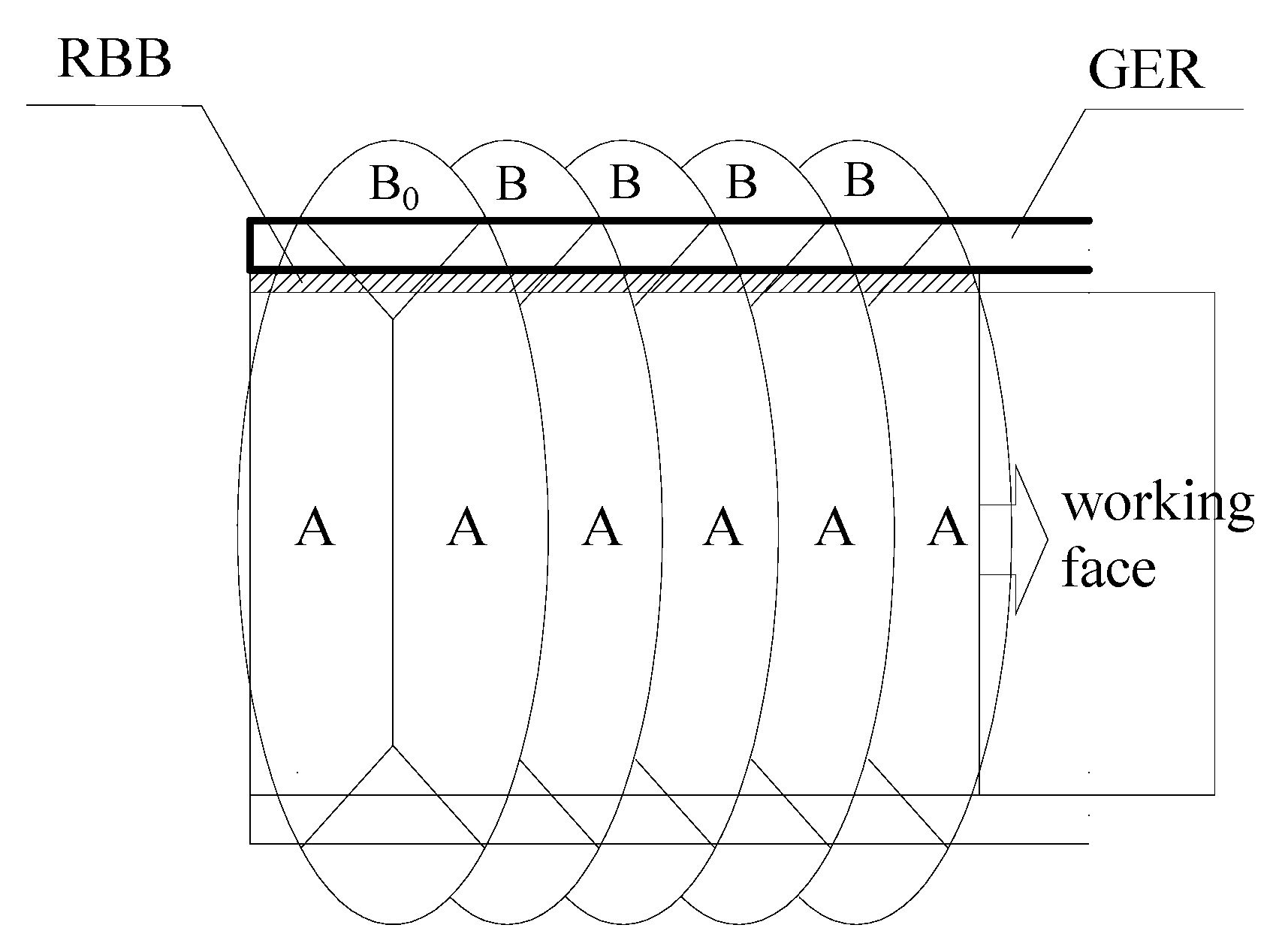
Figure 5 shows the main roof lateral fracture characteristics. The main roof fractures and forms an “O-X” structure due to the first weighting, and then the main roof block forms Block A and B0. The main roof block forms arc-shaped triangular Block B at the end of the working face due to periodic weighting. The retained entry is just under Block B. The movement rule and fracture characteristics of Block B play a key role in the surrounding rock control of GER. According to the movement rule and fracture characteristics of Block B during the GER stage, the Block B movement can be divided into soft roof fracture state (immediate roof) and hard roof fracture stage (main roof) [32].
(1)
Soft roof fracture state (immediate roof): As the working face advances, the roadside backfill body (RBB) is constructed. The immediate roof behind the active working face fractures along the RBB edge due to the early RBB support resistance and the roof weight. During this stage, Block B forms and rotates (see Figure 6a).
(2)
Hard roof fracture stage (main roof): Block B fractures and forms Blocks B1 and B2 as the tensile stress of Block B is greater than its ultimate tensile strength. Block B1 rotates towards the gob due to the abutment pressure behind the active working face (see Figure 6b).

3.2. Difficulties in Surrounding Rock Control for GER with Soft Roof, Floor, and Seam in TCMs

It is necessary to reduce the GER cost based on the conditions of the surrounding rock stability of GER and the requirements of the ventilation section. Combined with the mining and geological conditions of the 1103 working face in the Heilong Coal Mine, some difficulties in surrounding rock control for GER with soft roof, floor, and seam in TCMs was proposed as follows:
(1)
Solid coal rib stability control is difficult. Due to the soft surrounding rock (soft roof, floor, and seam), the roof structure would be far away from the retained entry, and the retained entry would be subjected to dynamic pressure action for a long time. Under this condition, the solid coal rib would be severely deformed.
(2)
The mechanical properties of the RBB should be appropriate. It is easy for the RBB to bump, crack, and even slip down due to the horizontal thrust of the rotated main roof. Therefore, the RBB must be stable and have some yieldability to adapt the roof sink and rotation. Moreover, the resistance of the RBB is able to cut the roof along the gob.
(3)
Soft roof control is difficult to keep stable. The immediate roof is mudstone with little strength and stiffness. As the working face advances, it is easy for the soft roof above the RBB to fracture and cave. Therefore, reasonable control technology should be adopted to keep the roof stable, realize the support resistance transfer between the RBB and the overlying strata, and effectively cut off the immediate roof along the gob.

3.3. Surrounding Rock Stability Control Technology for GER with Soft Roof, Floor, and Seam in TCMs

3.3.1. Support Technology of Prestressed RBB with High Resistance and Quick-Setting

Support technology of prestressed RBBs with high resistance and quick-setting includes construction technology of RBBs with high resistance and quick-setting, prestressed bearing technology.
(1) Construction technology of RBBs with high resistance and quick-setting
High-water quick-setting materials with high strength are used to construct the RBB. According to previous laboratory results, when the water-cement ratio is 1.5:1, the initial setting time of high-water quick-setting materials is 10 min, uniaxial compressive strength after setting for 24 h is 9.14 MPa, and uniaxial compressive strength after setting for 7 days is 10.36 MPa [31,33].
(2) Prestressed bearing technology of RBBs
Reinforcement components, including cross bolts, steel mesh, and ladder beams, are set up in the RBB bag before regular filling with the high-water, quick-setting material seriflux into the RBB bag. After the filling procedure and setting for 24 h, prestress is applied to the cross bolts to form the prestressed bearing structure.

3.3.2. Road-in Support Technology of “Roof Control and Coal Rib Reinforcement” for GER with Soft Roof, Floor, and Seam in TCMs

According to the difficulties in surrounding rock control for GER with soft roof, floor, and seam in TCMs, the surrounding rock control principle of “roof control and coal rib reinforcement” is put forward [32]. “Roof control” means that the roof is supported by high strength and high pre-stress bolts and anchor cables to enlarge the roof stiffness, improve the non-deformability, and reduce the main roof rotation. “Coal rib reinforcement” means that the solid coal rib is supported by high strength and high pre-stress bolts to enhance the bearing capacity of the solid coal rib and reduce the plastic failure radius. Moreover, during the GER stage, single hydraulic props with high resistance pressure are adopted to effectively support the roof and floor, reduce the roof rotation and subsidence, and maintain the stability of the surrounding rock for GER with soft roof, floor, and seam in the TCM.

3.3.3. Roof Support Technology above RBBs for GER with Soft Roof, Floor, and Seam in TCMs

Roof support technology above RBBs for GER with soft roof, floor, and seam in TCMs mainly includes:
(1)
Anchoring technology for the roof above the RBB. Anchor cables and bolts can be set up before the RBB is constructed. The roof above the RBB would change from unloading state in the vertical direction into triaxial compressive stress state, avoiding strong tensile damage and restraining the further development of joints and cracks in the roof rock mass.
(2)
High-strength polyester fiber mesh would be placed on the roof above the RBB ahead of four to five hydraulic supports at the end of the working face after cutting the coal. The integrity of the roof above the RBB would be improved.
(3)
A reasonable primary filling length is essential. According to the space and time coordination relationship between the support techniques, a reasonable primary filling length can be obtained to diminish the hanging roof area above the RBB, avoid further rotation and subsidence of the main roof, construct the RBB in time, and ensure that the RBB supports the roof in time.

4. Key Parameter Design for GER with Soft Roof, Floor, and Seam in TCMs

4.1. Support Resistance of RBBs for GER with Soft Roof, Floor and Seam in TCMs

Since the roof plays a key role in surrounding rock control and overlying strata movement, superposition of a continuous layer board mechanical model is established to analyze the relationship between the RBB and the roof for GER with soft roof, floor, and seam in TCMs [41]. According to the action of the solid coal rib and the method of roof load band segmentation, the mechanical model is established, as shown in Figure 7. Therefore, this mechanical model can be divided into two stages: (1) Soft roof (immediate roof) fracture stage; (2) Hard roof (main roof) fracture stage.
For the gob temporary support section (DE shown in Figure 7a), according to the mechanical equilibrium method, there are the following equilibrium equations:
{ F y = F M 1 γ i h i L Δ = 0 M D = M pi γ i h i L Δ 2 / 2 = 0
where FM1 is the shear force due to soft roof (immediate roof) fracture at point D with unit width (unit: N); γi is the bulk density of the immediate roof (unit: MN/m3); hi is the height of the immediate roof (unit: m); LΔ is the gob temporary support length (unit: m); Mpi is the ultimate bending moment at the immediate roof fracture point with unit width (unit: N·m).
For the AD section shown in Figure 7a, according to the mechanical equilibrium method, there are the following equilibrium equations.
M A = M A 1 M pi γ i h i ( x 0 + a + d ) 2 / 2 F M 1 ( x 0 + a + d ) + F R 1 ( x 0 + a + d / 2 ) + 0 x 0 σ y ( x 0 x ) d x = 0
where a is the width of the retained entry (unit: m); d is the width of the RBB (unit: m); FR1 is the support resistance of the RBB with unit length (unit: N/m); MA1 is the bending moment of the immediate roof (unit: N·m), MA1=σtihi2/6, σti is the tensile strength of the immediate roof (unit: MPa); x0 is the limit equilibrium area width (unit: m), which can be obtained by the following, Equation (3); and σy is the solid coal rib abutment pressure (unit: MPa), which can be obtained by the following, Equation (4):
x 0 = h c A 2 tan φ ln ( k γ H + c tan φ c tan φ + p x A )
σ y = ( c tan φ + p x A ) e 2 tan φ h c A x c tan φ
where c is the cohesion of the solid coal (unit: MPa); φ is the friction angle of the solid coal (unit: °); px is the support strength of the solid coal rib (unit: MPa); A is the coefficient of horizontal pressure; hc is the coal seam height (unit: m); k is the stress concentration factor; H is the coal seam buried depth (unit: m); and γ is the bulk density of overlying strata (unit: MN/m3).
Therefore, the support resistance calculation of the RBB when the soft roof fractures (FR1) is as follows:
F R 1 = γ i h i ( x 0 + a + d ) 2 / 2 x 0 + a + d / 2 + F M 1 ( x 0 + a + d ) x 0 + a + d / 2 + M pi x 0 + a + d / 2 0 x 0 σ y ( x 0 x ) d x + M A 1 x 0 + a + d / 2
Similarly, the support resistance calculation of the RBB when the main roof fractures (FR2) is as follows:
F R 2 = γ i h i ( x 0 + a + d ) 2 / 2 + ( γ m h m + q ) L b 2 / 2 x 0 + a + d / 2 + F M 1 ( x 0 + a + d ) + F M 2 L m x 0 + a + d / 2 + M pm x 0 + a + d / 2 0 x 0 σ y ( x 0 x ) d x + M A 1 + M A 2 x 0 + a + d / 2
where γm is the bulk density of the main roof (unit: MN/m3); hm is the height of the main roof (unit: m); MA2 is the bending moment of the main roof (unit: N·m), MA2 = σtmhm2/6, σtm is the tensile strength of the main roof (unit: MPa); Mpm is the ultimate bending moment at the main roof fracture point with unit width (unit: N·m); FM2 is the shear force due to main roof fracture at point D with unit width (unit: N); Lm is the feature size of the main roof fracture (unit: m), Lm = x0 + a + d + hmcotθ; θ is the angle of the main roof fracture; and q is the load overlying soft strata (unit: MPa), which can be assumed as the rock weight according to four to eight times the coal seam height.
According to the mining and geological conditions and rock mechanics test results of the 1103 working face in the Heilong Coal Mine, these relevant values can be obtained as follows: H = 210 m, LΔ = 2 m, hc = 1.3 m, a = 4.5 m, d = 2.0 m, γ = 2.5 × 10⁻² MN/m3, A = 0.8, K = 1.5, c = 3.0 MPa, φ = 30°, px = 0.2 MPa, θ = 55°, q = 0.2 MPa, σti = 0.3 MPa, γi = 2.5 × 10⁻² MN/m3, hi = 1.1 m, σtm = 1.7 MPa, γm = 2.5 × 10⁻² MN/m3, hm = 3.4 m. Thereby, by using MATHCAD software, FR1 and FR2 can be determined, that is, 0.0045 MN/m and 5.58 MN/m.

4.2. RBB Width and Strength for GER with Soft Roof, Floor, and Seam in TCMs

In fact, the roadside support resistance of the RBB is the product of RBB width and the support strength of the RBB (σRBB). The RBB width can be calculated as follows:
d = max { F R 1 σ RBB ,   F R 2 σ RBB }
According to GER engineering cases with high-water quick-setting materials (see Table 1), it is found that the common water-cement ratio of the high-water quick-setting materials is 1.5:1.
According to the above results, the support resistance of the RBB when the main roof fractures are 5.58 MN/m. When the water-cement ratio of high-water quick-setting material is 1.5:1, the uniaxial compressive strength of backfill is 9.14 MPa after 24 h, measured in the laboratory. In the field construction, the strength of backfill is calculated as 80% of the laboratory test value. Taking 1.3 times the safety factor into account, the theoretical width of the RBB for the 1103 working face for 1 day is calculated as 0.99 m based on Equation (6). Therefore, the RBB width is 1.0 m.

5. Engineering Practice

5.1. Field Test

(1) No.1103 haulage roadway reinforcement support
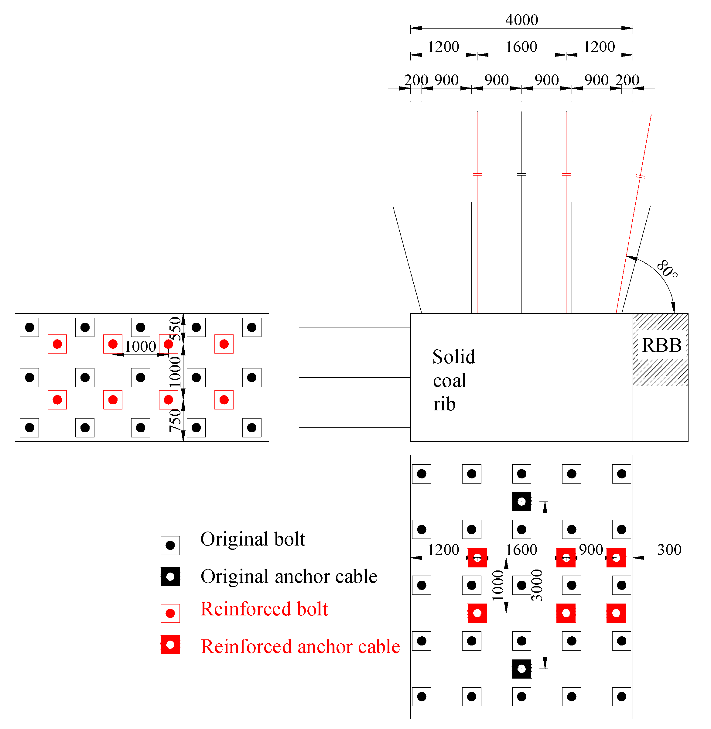
The roof is reinforced by Φ17.8 mm × L6300 mm anchor cables, and three rows are set up with a spacing of 800 mm along the roadway. The anchor cables are arranged by a steel ladder beam welded with round steel, 16 mm in diameter and 2700 mm long. The solid coal rib is reinforced by Φ18 mm × L2000 mm bolts; two rows are set up with a spacing of 1000 mm along the roadway. The bolts are arranged by the steel ladder beam welded with round steel, 14 mm in diameter and 1200 mm long. The detailed reinforcement support parameters are as shown in Figure 8.
(2) RBB construction
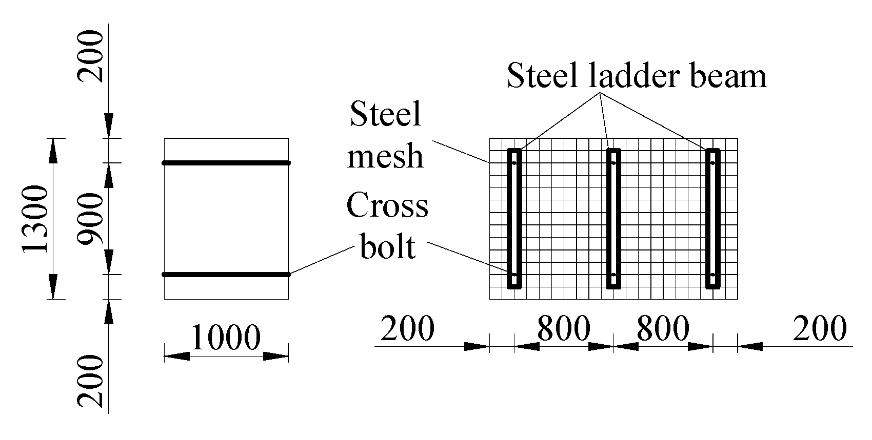
The designed RBB width is 1.0 m, and the water-cement ratio of the high-water quick-setting materials is 1.5:1. Cross bolts (Φ22 mm × L2000 mm) are placed in the RBB to improve the RBB capacity. Two rows of cross bolts are placed with a spacing of 800 mm along the roadway. The cross bolts are made of Φ22 mm rebar. The cross bolts are arranged by the steel ladder beam welded with round steel, 14 mm in diameter and 1200 mm long. The RBB is wrapped by steel mesh made of Φ6.5 mm steel. The detailed RBB construction is shown in Figure 9.
(3) Roof support above RBBs
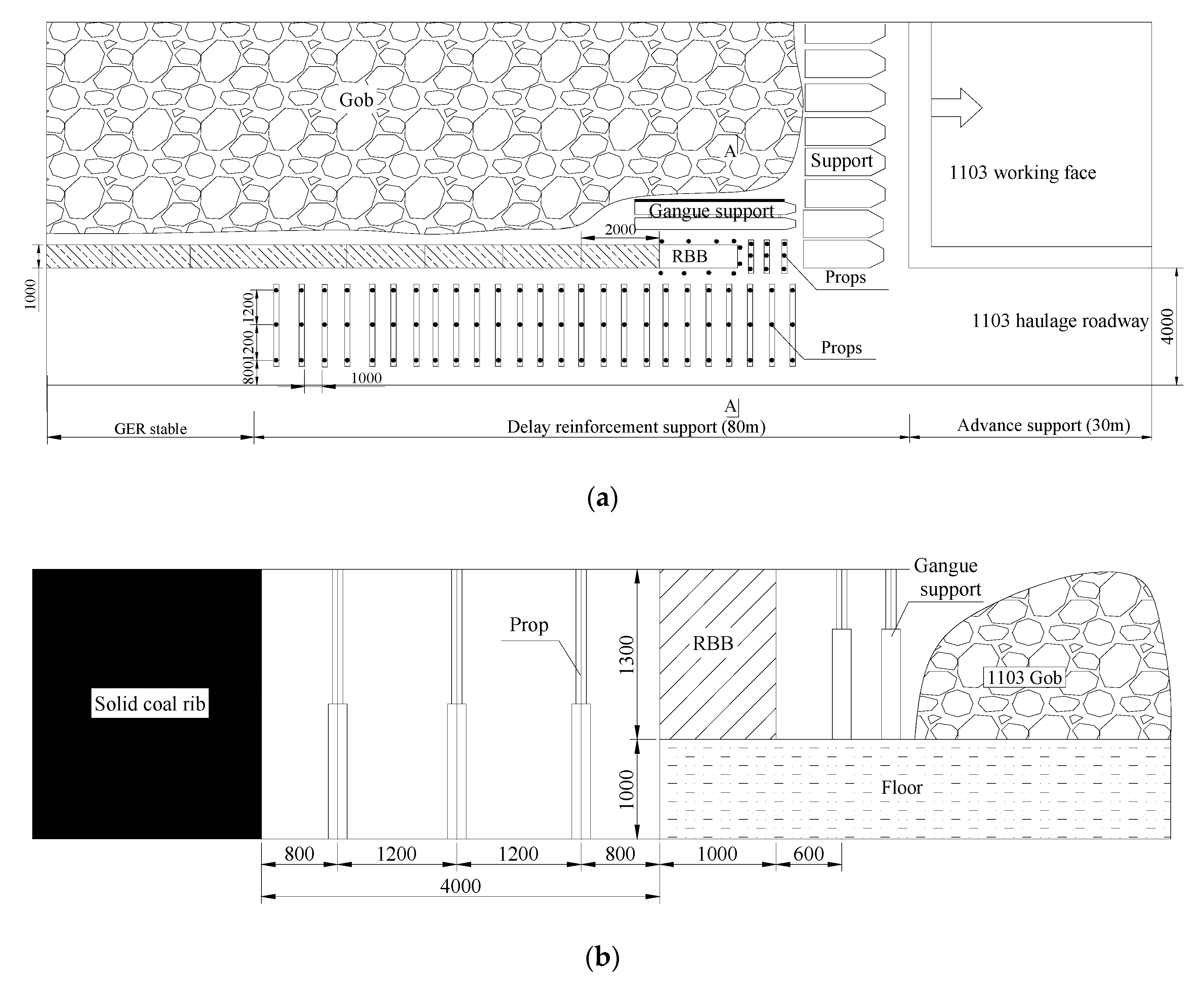
High-strength polyester fiber mesh is placed on the roof above the RBB ahead of four hydraulic supports at the end of the working face after cutting the coal. Then, hydraulic supports are moved, and single hydraulic props with metal hinge top beams are used to temporarily support the unfilled zone. Moreover, a row of reinforcement anchor cables inclined to the gob are used to support the roof above the RBB (see Figure 8). The detailed roof support above the RBB is shown in Figure 10.
(4) Reinforcement support behind the active 1103 working face
In order to improve the surrounding rock stability for GER with soft roof, floor, and seam in the TCM, three rows of single hydraulic props are used to support the roof and floor behind the active 1103 working face. Single hydraulic props are retained with a spacing of 1000 mm, as shown in Figure 10.

5.2. Field Monitoring

Figure 11 shows the surrounding rock deformation during retaining the No. 1103 haulage roadway. It can be seen that:
(1)
The No. 1103 haulage roadway suffers mining stress 40 m ahead of the active 1103 working face. However, the obvious deformation appears 18 to 20 m ahead of the active 1103 working face. The total solid coal rib to excavation rib convergence along the middle of the rib (AC direction) reaches 99.2 mm, while the total floor to roof convergence along the middle of the roadway (BD direction) reaches 167.7 mm ahead of the active 1103 working face.
(2)
Surrounding rock characteristics of GER behind the active 1103 working face can be divided into three stages. The first stage is 0 to 10 m behind the active 1103 working face, where the surrounding rock deformation is relatively small. The second stage is 10 to 60 m behind the active 1103 working face, where the surrounding rock deformation is intensively due to the periodic weighting and main roof fracture. The third stage is more than 60 m behind the active 1103 working face, where the surrounding rock deformation is almost stable. The total solid coal rib to excavation rib convergence along the middle of the rib (AC direction) reaches 263.5 mm, while the total floor to roof convergence along the middle of the retained roadway (BD direction) reaches 495.4 mm behind the active 1103 working face.
(3)
The solid coal rib to excavation rib convergence is consistently more than the floor to roof convergence, especially behind the active 1103 working face. The final deformation difference of the solid coal rib to excavation rib convergence and the floor to roof convergence is 316.9 mm.
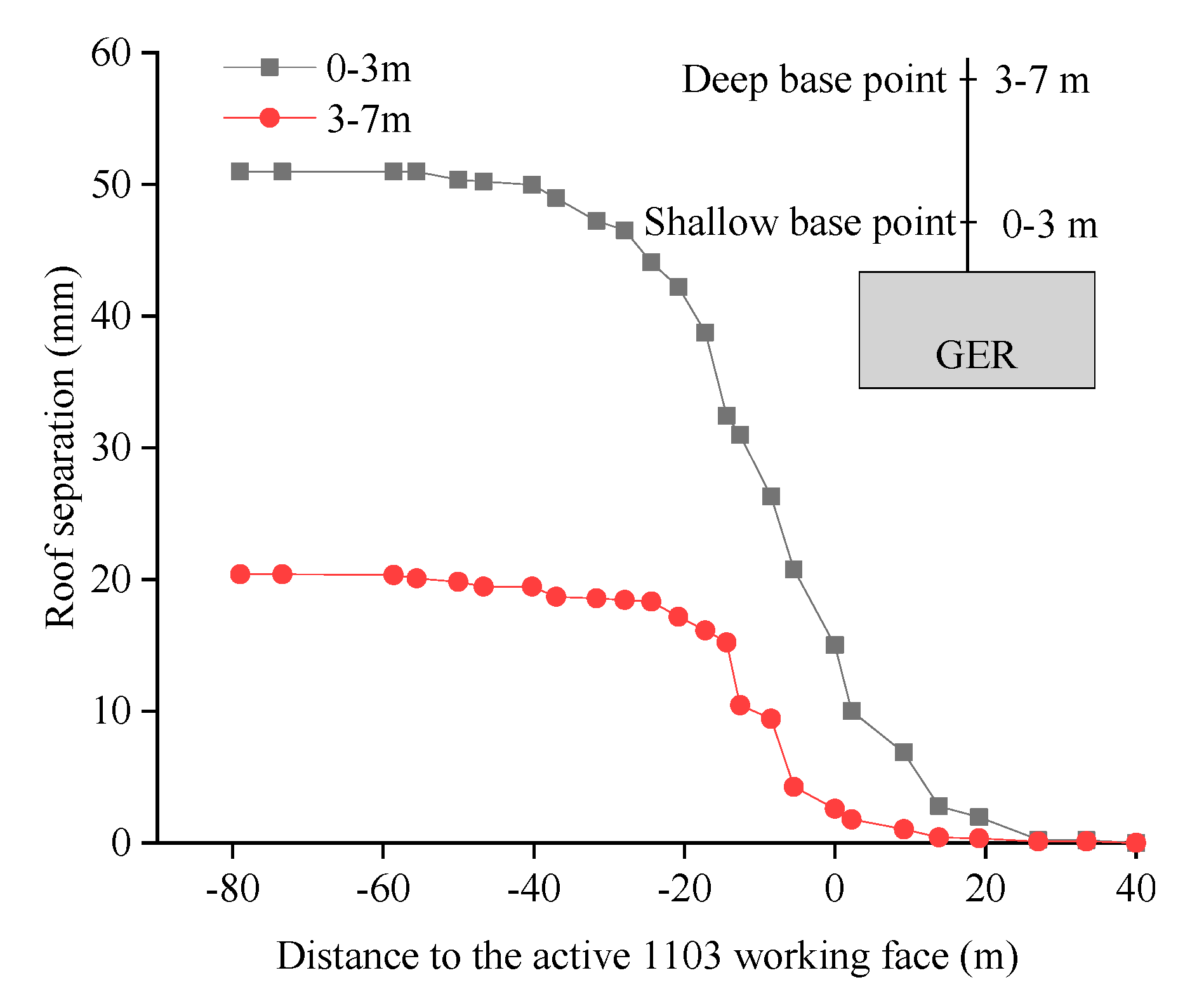
Figure 12 shows the roof separation during the retention of the No. 1103 haulage roadway. It can be seen that no instability separation occurs in the roof anchorage zone. Most of the roof separation occurs between 20 m ahead of the active 1103 working face and 40 m behind the active 1103 working face due to roof movement. Roof separation more than 40 m behind the active 1103 working face keeps stable. Finally, the maximum separation value of the shallow base point is 51 mm, and the maximum separation value of the deep base point is 21 mm. The roof separation value of the roadway is relatively small. It shows that the roof subsidence is effectively controlled by the high-strength bolts, anchor cables, and steel ladder support system, and the roof is safe and stable.
Figure 13 shows the RBB load during the retention of the No. 1103 haulage roadway. It can be seen that the RBB load is less than 2 MPa 0 to 10 m behind the active 1103 working face. The RBB load increases sharply 10 to 30 m behind the active 1103 working face and reaches a maximum of 8.6 MPa with the rotation and subsidence of the main roof. The RBB load remains at 7.1 MPa more than 40 m behind the active 1103 working face. It shows that the RBB with high-water, quick-setting materials has a high resistance, which increases speed, maintains the integrity of the retained roadway roof effectively, adapts the main roof rotation and subsidence, avoids the roof instability separation, and effectively controls the surrounding rock deformation.
The field test shows that high strength bolts, anchor cables, and steel beams used as the basic support, single hydraulic props with metal hinge top beams used as the reinforcement support, and prestressed RBB used as the roadside support, effectively control the surrounding rock deformation for GER with soft roof, floor, and seam in TCMs. The retained roadway meets the requirements of air return and safe mining and reaches the expected requirements for GER.

6. Discussion

6.1. Influence on Surrounding Rock Stability of RBB Width and Strength for GER with Soft Roof, Floor, and Seam in TCMs

6.1.1. Numerical Model and Verification

According to the geological and mining conditions of the 1103 working face in the Heilong Coal Mine, a numerical model was established using the discrete element method software UDEC [46,47]. The dimensions of the numerical model are 110 m × 71.65 m (length × height). The basic numerical model consists of part of the 1103 working face (50 m), part of the 1105 working face (50 m), RBB (1.0 m), and retained roadway (4.0 m). The top boundary of the model is the stress boundary, the bottom boundary is the fixed vertical displacement, and the left and right boundary is fixed horizontally. In the calculation of the model, the Mohr-Coulomb model is used for the block model. The yield weakening model is used to consider the influence of mining in the joint model.
On the basis of the laboratory results for the mechanical properties of rock and coal samples, the parameters employed in the model have been determined. The final rock strata property parameters in the numerical model are shown in Table 2. The modeling process is as follows: (i) Establishing model; (ii) calculating the initial rock stress state; (iii) modeling the excavations of the No. 1103 haulage roadway; (iv) retreating the 1103 working face and roadside backfill; (v) changing one factor and repeating the above process.

6.1.2. Influence on Surrounding Rock Stability of RBB width for GER with Soft Roof, Floor, and Seam in TCMs

Figure 14 shows the vertical stress distributions of the surrounding rock for GER with respect to RBB width (water cement ratio is 1.5:1 in all models). With the increase of RBB width, the bearing capacity of the RBB is higher and the surrounding rock of GER is more stable. When the RBB width is 0.5 m, the RBB would be in a state of residual strength, which indicates that the RBB has been crushed and the surrounding rock of GER cannot be stable. RBB support is a passive support, which cannot change the movement mode of the main roof and avoid the rotation of the main roof.
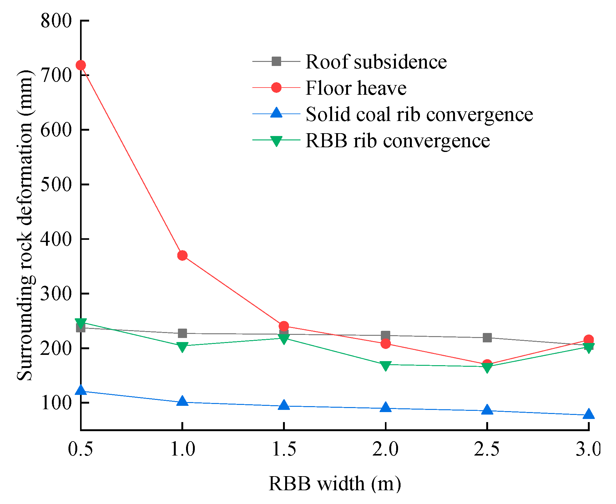
As shown in Figure 15, the influence level from high to low is floor heave, RBB rib convergence, roof subsidence, and solid coal rib convergence. When the RBB width is above 1.0 m, the RBB rib convergence and roof subsidence decrease significantly. With the further increase of RBB width, the RBB rib convergence and roof subsidence still decreases, but to a smaller extent. Therefore, when the RBB width is over 1.0 m, the RBB can maintain the roof and cut off the roof outside of the RBB to promote the surrounding rock stability of GER as soon as possible.

6.1.3. Influence on Surrounding Rock Stability of Water Cement Ratio (RBB strength) for GER with Soft Roof, Floor, and Seam in TCMs

Figure 16 shows the vertical stress distributions of the surrounding rock for GER with respect to water cement ratio (RBB width is 1.0 m in all models). With the increase of water cement ratio, the vertical stress of the solid coal rib increases and the location of the peak vertical stress of the solid coal rib moves away from the GER. Meanwhile, with the increase of water cement ratio, the vertical stress of the RBB rib decreases and the deformation of GER increases. Therefore, it is further proved that an RBB with the current width cannot change the movement mode of the main roof.
As shown in Figure 17, when the water cement ratio of high-water, quick-setting materials is 1.5:1, the roof subsidence is 227 mm, the floor heave is 369.9 mm, the RBB rib convergence is 204.2 mm, and the solid coal rib convergence is 101.2 mm. When the water cement ratio of high-water, quick-setting materials is 2.0:1, the above deformation amounts are, respectively, 244.9 mm, 802.2 mm, 279.6 mm, and 119.9 mm. When the water cement ratio of high-water, quick-setting materials is 2.5:1, the above deformation amounts are, respectively, 249.5 mm, 876.8 mm, 374 mm, and 153.3 mm. It can be seen that the surrounding rock deformation increases as the water cement ratio increases (RBB strength decreases); in particular, the RBB rib convergence and floor heave increase rapidly under the condition of the same RBB width.

6.2. Influence Factors of Roof Stability for GER with Soft Roof, Floor, and Seam in TCMs

6.2.1. Influence on Roof Stability for GER with Respect to Immediate Roof Height

The monitoring line is placed at 0.55 m above the immediate roof, and the roof subsidence and vertical stress above the RBB with the immediate roof height at 1.1 m, 5.0 m, and 10 m are studied by numerical simulation. The results are shown in Figure 18, in which “+” indicates compressive stress and “−” indicates tensile stress (Figure 18b). It can be seen that the roof subsidence above the RBB is larger than that of the retained roadway, and the roof subsidence is linearly negatively related to the distance to the outer edge of the RBB, whatever the immediate roof height is. Moreover, with the increase of the immediate roof height, the roof subsidence decreases. In fact, as the immediate roof height increases, the stiffness of the immediate roof gradually decreases, and the ability of the immediate roof to absorb the deformation energy is gradually enhanced. Therefore, roof vertical stress distribution characteristics with respect to immediate roof height can be summarized as follows, as seen in Figure 18b:
(1)
The roof vertical stress decreases and then increases as the distance to the outer edge of the RBB increases. That is, the vertical stress distribution in the roof is V-shaped. The minimum roof vertical stress is basically located at the middle of the retained roadway, and the minimum roof vertical stress increases with the increase of the immediate roof height. The roof vertical stress close to the gob is larger than that close to the retained roadway.
(2)
The roof vertical stress above the RBB close to the gob is higher than the in-situ stress, and the vertical stress above the RBB close to the retained roadway is lower than the in-situ stress. Tensile stress appears in the middle of the retained roadway roof, and the distribution width of roof tensile stress increases with the increase of the immediate roof height.
(3)
The roof vertical stress increases as the distance to the edge of the solid coal rib increases.

6.2.2. Influence on Roof Stability for GER with Respect to Main Roof Height

Figure 19 shows the roof subsidence and vertical stress with respect to main roof height (3.4 m, 10 m, 20 m). It can be seen that the roof subsidence above the RBB is larger than that of the retained roadway, and the roof subsidence is linearly negatively related to the distance to the outer edge of the RBB, whatever the main roof height is. Moreover, the roof subsidence decreases as the main roof height increases. In fact, with the increase of the immediate roof height, the ability of the immediate roof to absorb the deformation energy increases. Therefore, roof vertical stress distribution characteristics with respect to main roof height can be summarized as follows, as seen in Figure 19b:
(1)
As the distance to the outer edge of the RBB increases, the roof vertical stress above the RBB increases and then decreases. That is, the vertical stress distribution in the monitoring roof above the RBB is Ʌ-shaped. The roof vertical stress above the RBB close to the gob decreases and then increases as the height of the main roof increases. The roof vertical stress above the RBB close to the retained roadway increases and then decreases as the height of the main roof increases.
(2)
As the distance to the outer edge of the RBB increases, the vertical stress distribution in the monitoring roof is N-shaped. The minimum roof vertical stress is basically located at the middle of the retained roadway, and the minimum roof vertical stress increases as the height of the main roof increases. Tensile stress appears in the middle of the retained roadway roof, and the distribution width of roof tensile stress increases with the increase of the main roof height.
(3)
As the distance to the edge of the solid coal rib increases, the roof vertical stress above the solid coal rib increases. With the increase of the main roof height, the roof vertical stress above the solid coal rib decreases.

6.2.3. Influence on Roof Stability for GER with Respect to GER Width

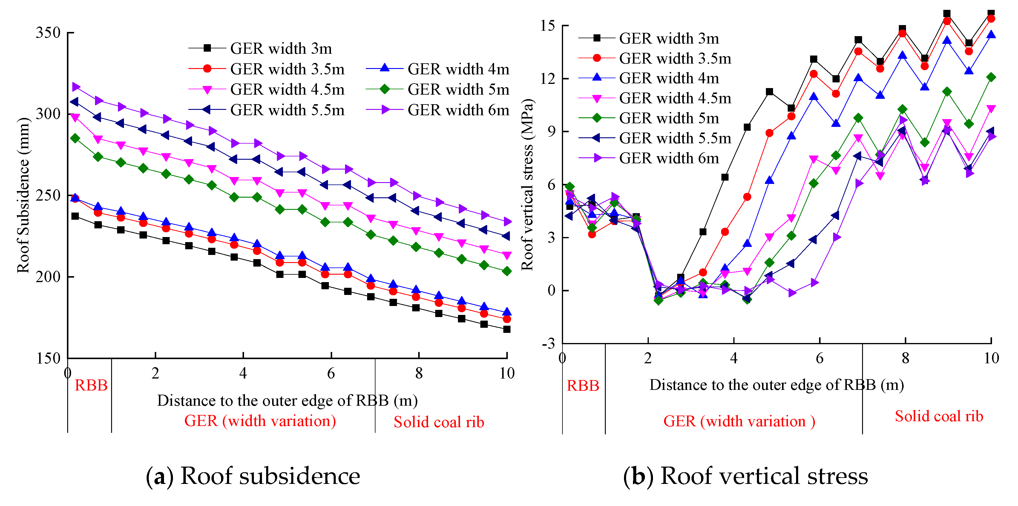
Figure 20 shows the roof subsidence and vertical stress with respect to GER width (3.0 m, 3.5 m, 4.0 m, 4.5 m, 5.0 m, 5.5 m, 6.0 m). It can be seen that the roof subsidence above the RBB is larger than that of the retained roadway. As the distance to the outer edge of the RBB increases, the roof subsidence close to the gob decreases more quickly than that close to the retained roadway. Moreover, the roof subsidence increases as the GER width increases, especially when the GER width is more than 4.0 m. Therefore, roof vertical stress distribution characteristics with respect to GER width can be summarized as follows, as seen in Figure 20b:
(1)
When the GER width is no more than 5.0 m, the roof vertical stress above the RBB decreases as the distance to the outer edge of the RBB increases. When the GER width is more than 5.0 m, the roof vertical stress above the RBB increases as the distance to the outer edge of the RBB increases
(2)
As the distance to the outer edge of the RBB increases, the roof vertical stress above the retained roadway increases and then decreases. That is, the vertical stress distribution in the monitoring roof above the retained roadway is V-shaped. The minimum roof vertical stress is basically located at the middle of the retained roadway. Tensile stress appears in the middle of the retained roadway roof, and the distribution width of roof tensile stress increases with the increase of the GER width.
(3)
With the increase of the GER width, the roof vertical stress above the solid coal rib decreases.

6.2.4. Influence on Roof Stability for GER with Respect to RBB Width

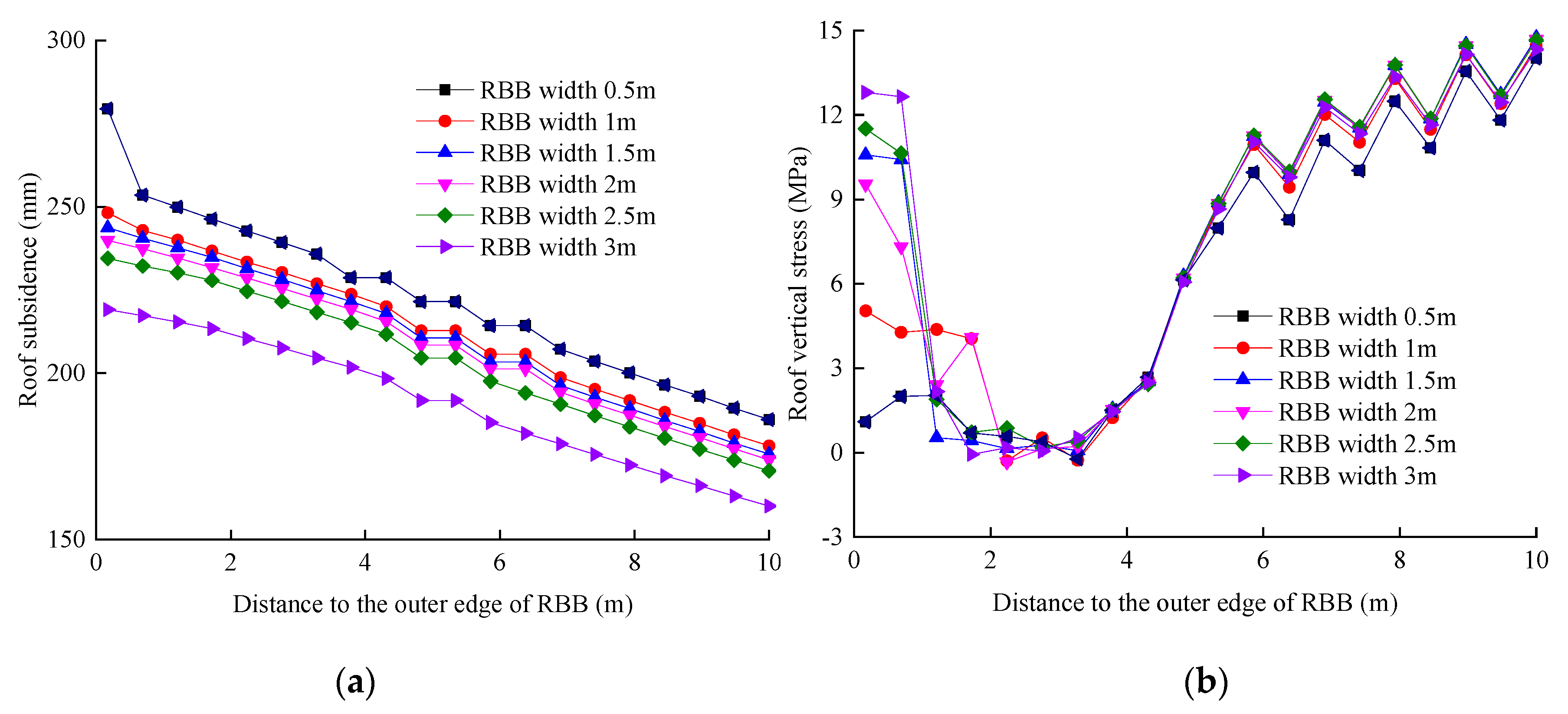
Figure 21 shows the roof subsidence and vertical stress with respect to RBB width (0.5 m, 1.0 m, 1.5 m, 2.0 m, 2.5 m, 3.0 m). It can be seen that the roof subsidence above the RBB is larger than that of the retained roadway, whatever the RBB width is. Moreover, the roof subsidence decreases as the RBB width increases. Therefore, roof vertical stress distribution characteristics with respect to RBB width can be summarized as follows, as seen in Figure 21b:
(1)
When the RBB width is more than 0.5 m, the roof vertical stress above the RBB decreases as the distance to the outer edge of the RBB increases. When the GER width is more than 0.5 m, the roof vertical stress above the RBB is “Ʌ” shaped as the distance to the outer edge of the RBB increases. The roof vertical stress above the RBB decreases as the RBB width increases.
(2)
Tensile stress appears in the middle of the retained roadway roof, and the distribution width of roof tensile stress decreases with the increase of the RBB width.
(3)
With the increase of the RBB width, the roof vertical stress above the solid coal rib increases.

7. Conclusions

Surrounding rock stability control of GER with soft roof, floor, and seam in TCMs has great challenges and difficulties. In this paper, surrounding rock stability control technology with three parts is proposed by analyzing the structural characteristics of overburden strata and difficulties in surrounding rock control for GER with soft roof, floor, and seam in TCMs. These surrounding rock stability control technologies include a support technology of prestressed RBBs with high resistance and quick-setting, road-in support technology of “roof control and coal rib reinforcement”, and roof support technology above the RBB.
Key parameters including RBB width, RBB support resistance, and water cement ratio of high-water, quick-setting materials are obtained by theoretical calculations based on the superposition of a continuous layer board mechanical model to analyze the relationship between the RBB and the roof for GER with soft roof, floor, and seam in TCMs. The results indicate that RBB width is 1.5 m, RBB support resistance to cut off the main roof is 5.58 MN/m, and water cement ratio of high-water, quick-setting materials is 1.5:1. A field test shows that the use of high strength bolts, anchor cables, and steel beams as the basic support, single hydraulic props with metal hinge top beams as the reinforcement support, and prestressed RBBs as the roadside support effectively control the surrounding rock deformation for GER with soft roof, floor, and seam in TCMs.
Furthermore, influence characteristics of vertical stress distribution and surrounding rock deformation with respect to RBB width and RBB strength (water cement ratio of high-water, quick-setting materials) for GER with soft roof, floor, and seam in TCMs are studied using the discrete element method software UDEC. Influence characteristics of roof subsidence and vertical stress with respect to immediate roof height, main roof height, RBB width, and GER width are also revealed.
Moreover, more and more TCMs below medium and hard coal could be mined out in China. In order to improve the coal recovery rate, GER of TCMs should be carried out to achieve the sustainable development of coordinated mining. Stability maintenance of the GER of TCMs with soft surrounding rock and environmentally friendly RBB backfill materials should also be developed in future studies. GER for different geological conditions should be studied to develop a sustainable coal mining industry.

Author Contributions

Z.T. conceived and designed this paper; J.B. and Z.Z. amended this paper; S.Y. and M.D. helped to review this paper. All authors have read and agreed to the published version of the manuscript.

Funding

This work is supported by the Fundamental Research Funds for the Central Universities (2018ZDPY02).

Conflicts of Interest

The authors declare no conflict of interest.

References

  1. Yang, H.Y.; Cao, S.G.; Wang, S.Q.; Fan, Y.C.; Wang, S.; Chen, X.Z. Adaptation assessment of gob-side entry retaining based on geological factors. Eng. Geol. 2016, 209, 143–151. [Google Scholar] [CrossRef]
  2. Tan, Y.L.; Yu, F.H.; Ning, J.G.; Zhao, T.B. Design and construction of entry retaining wall along a gob side under hard roof stratum. Int. J. Rock Mech. Min. Sci. 2015, 77, 115–121. [Google Scholar] [CrossRef]
  3. Zhang, N.; Yuan, L.; Han, C.L.; Xue, J.H.; Kan, J.G. Stability and deformation of surrounding rock in pillarless gob-side entry retaining. Saf. Sci. 2012, 50, 593–599. [Google Scholar] [CrossRef]
  4. Wang, H.S.; Zhang, D.S.; Liu, L.; Guo, W.B.; Fan, G.W.; Song, K.; Wang, X.F. Stabilization of Gob-Side Entry with an Artificial Side for Sustaining mining work. Sustainability 2016, 8, 627. [Google Scholar] [CrossRef] [Green Version]
  5. Zhang, Z.Y.; Shimada, H.; Sasaoka, T.; Hamanaka, A. Stability control of retained goaf-side gateroad under different roof conditions in deep underground y type longwall mining. Sustainability 2017, 9, 1671. [Google Scholar] [CrossRef] [Green Version]
  6. Luan, H.J.; Jiang, Y.J.; Lin, H.L.; Li, G.F. Development of a new gob-side entry-retaining approach and its application. Sustainability 2018, 10, 470. [Google Scholar] [CrossRef] [Green Version]
  7. Kang, H.P.; Niu, D.L.; Zhang, Z.; Lin, J.; Li, Z.H.; Fan, M.J. Deformation characteristics of surrounding rock and supporting technology of gob-side entry retaining in deep coal mine. Chin. J. Rock Mech. Eng. 2010, 29, 1977–1987. [Google Scholar]
  8. Zhang, B.; Ma, Z.Y.; Wang, X.; Zhang, J.S.; Peng, W.Q. Reliability analysis of anti-seismic stability of 3D pressurized tunnel faces by response surfaces method. Geomech. Eng. 2020, 20, 43–54. [Google Scholar]
  9. Yin, Y.C.; Zhao, T.B.; Zhang, Y.B.; Tan, Y.L.; Qiu, Y.; Taheri, A.; Jing, Y. An innovative method for placement of gangue backfilling material in steep underground coal mines. Minerals 2019, 9, 107. [Google Scholar] [CrossRef] [Green Version]
  10. Ma, L.Q.; Zhang, D.S.; Chen, T.; Fan, G.W. Study on packing body supporting resistance of enter-in packing for in-situ gob-side entry retaining in fully mechanized top-coal caving mining face. Chin. J. Rock Mech. Eng. 2007, 26, 544–550. [Google Scholar]
  11. Ning, J.G.; Liu, X.S.; Tan, J.; Gu, Q.H.; Tan, Y.L.; Wang, J. Control mechanisms and design for a “coal-backfill-gangue” support system for coal mine gob-side entry retaining. Int. J. Oil Gas Coal Tech. 2018, 18, 444–466. [Google Scholar] [CrossRef]
  12. Liu, X.S.; Ning, J.G.; Tan, Y.L.; Gu, Q.H. Coordinated supporting method of gob-side entry retaining in coal mines and a case study with hard roof. Geomech. Eng. 2018, 15, 1173–1182. [Google Scholar]
  13. Wang, Q.; He, M.C.; Yang, J.; Gao, H.K.; Jiang, B.; Yu, H.C. Study of a no-pillar mining technique with automatically formed gob-side entry retaining for longwall mining in coal mines. Int. J. Rock Mech. Min. Sci. 2018, 110, 1–8. [Google Scholar] [CrossRef]
  14. Zhang, G.C.; Wen, Z.J.; Liang, S.J.; Tan, Y.L.; Tian, L.; Zhao, Y.Q.; Zhao, D.S. Ground response of a gob-side entry in a longwall panel extracting 17 m-thick coal seam: A case study. Rock Mech. Rock Eng. 2019. [Google Scholar] [CrossRef]
  15. Zhang, G.C.; Tan, Y.L.; Liang, S.J.; Jia, H.G. Numerical estimation of suitable gob-side filling wall width in a highly gassy longwall mining panel. Int. J. Geomech. 2018, 18, 04018091. [Google Scholar] [CrossRef]
  16. Li, X.H.; Ju, M.H.; Yao, Q.L.; Zhou, J.; Chong, Z.H. Numerical investigation of the effect of the location of critical rock block fracture on crack evolution in a gob-side filling wall. Rock Mech. Rock Eng. 2016, 49, 1041–1058. [Google Scholar] [CrossRef]
  17. Huang, W.P.; Yuan, Q.; Tan, Y.L.; Wang, J.; Liu, G.L.; Qu, G.L. An innovative support technology employing a concrete-filled steel tubular structure for a 1000 m-deep roadway in a high in situ stress field. Tunn. Undergr. Space Technol. 2018, 73, 26–36. [Google Scholar] [CrossRef]
  18. Chen, Y.; Bai, J.B.; Wang, X.Y.; Ma, S.Q.; Xu, Y.; Bi, T.F.; Yang, H. Support technology research and application inside roadway of gob-side entry retaining. J. China Coal Soc. 2012, 37, 903–910. [Google Scholar]
  19. Kong, P.; Jiang, L.S.; Shu, J.M.; Sainoki, A.; Wang, Q.B. Effect of fracture heterogeneity on rock mass stability in a highly heterogeneous underground roadway. Rock Mech. Rock Eng. 2019. [Google Scholar] [CrossRef]
  20. Wu, B.W.; Wang, X.Y.; Bai, J.B.; Wu, W.D.; Zhu, X.X.; Li, G.D. Study on crack evolution mechanism of roadside backfill body in gob-side entry retaining based on UDEC trigon model. Rock Mech. Rock Eng. 2019, 52, 3385–3399. [Google Scholar] [CrossRef]
  21. Wu, Q.H.; Chen, L.; Shen, B.T.; Dlamini, B.; Li, S.Q.; Zhu, Y.J. Experimental investigation on rockbolt performance under the tension load. Rock Mech. Rock Eng. 2019, 52, 4605–4618. [Google Scholar] [CrossRef]
  22. Duan, H.Q.; Sun, M.; Li, Q. A new gob-side entry retaining approach with reinforced filling gangue wall in thin coal seam. Geotech. Geol. Eng. 2019. [Google Scholar] [CrossRef]
  23. Wu, Q.H.; Li, X.B.; Weng, L.; Li, Q.F.; Zhu, Y.J.; Luo, R. Experimental investigation of the dynamic response of prestressed rockbolt by using an SHPB-based rockbolt test system. Tunn. Undergr. Space Technol. 2019, 93, 103088. [Google Scholar] [CrossRef]
  24. Han, C.L.; Zhang, N.; Xue, J.H.; Kan, J.G.; Zhao, Y.M. Multiple and long-term disturbance of gob-side entry retaining by grouped roof collapse and an innovative adaptive technology. Rock Mech. Rock Eng. 2019, 52, 2761–2773. [Google Scholar] [CrossRef]
  25. Feng, X.W.; Zhang, N. Position-optimization on retained entry and backfilling wall in gob-side entry retaining techniques. Int. J. Coal Sci Technol. 2015, 3, 186–195. [Google Scholar] [CrossRef] [Green Version]
  26. Zhang, Z.Z.; Wang, W.J.; Li, S.Q.; Yu, X.Y. Analysis on rockbolt support interaction with roof dilatancy above roadside backfill area in gob-side entry retaining. Geotech. Geol. Eng. 2018, 36, 2577–2591. [Google Scholar] [CrossRef]
  27. Ma, Q.; Tan, Y.L.; Zhao, Z.H.; Xu, Q.; Wang, J.; Ding, K. Roadside support schemes numerical simulation and field monitoring of gob-side entry retaining in soft floor and hard roof. Arabian J. Geosci. 2018, 11, 563. [Google Scholar] [CrossRef]
  28. Zhang, Z.Z.; Yu, X.Y.; Deng, M. Damage evolution of sandy mudstone mechanical properties under mining unloading conditions in gob-side entry retaining. Geotech. Geol. Eng. 2019, 37, 3535–3545. [Google Scholar] [CrossRef]
  29. Yan, S.; Liu, T.X.; Bai, J.B.; Wu, W.D. Key parameters of gob-side entry retaining in a gassy and thin coal seam with hard roof. Processes 2018, 6, 51. [Google Scholar] [CrossRef] [Green Version]
  30. Zhang, Z.Z.; Wang, W.J.; Li, S.Q.; Yu, X.Y. An innovative approach for gob-side entry retaining with thick and hard roof: A case study. Tech. Gaz. 2018, 25, 1028–1036. [Google Scholar]
  31. Zhang, Z.Z.; Bai, J.B.; Wang, W.J.; Chen, Y.; Yu, X.Y.; Wu, H. Mechanical analysis of roof separation within and outside anchorage zone above backfill area of gob-side entry retaining and its engineering application. J. Min. Saf. Eng. 2018, 25, 1028–1036. [Google Scholar]
  32. Zhang, Z.Z.; Bai, J.B.; Chen, Y.; Li, M. Investigation and application analysis of unbalanced bearing characteristics of gob-side entry retaining. Rock Soil Mech. 2015, 36, 2665–2673. [Google Scholar]
  33. Zhang, Z.Z.; Bai, J.B.; Chen, Y.; Yan, S. An innovative approach for gob-side entry retaining in highly gassy fully-mechanized longwall top-coal caving. Int. J. Rock Mech. Min. Sci. 2015, 80, 1–11. [Google Scholar] [CrossRef]
  34. Li, P. Research on gob-side entry retaining with waste filling in close thin seam with hard roof and floor. China Coal. 2017, 43, 67–71. [Google Scholar]
  35. Zhang, J.X.; Jiang, H.Q.; Miao, X.X.; Zhou, N.; Zan, D.F. The rational width of the support body of gob-side entry in fully mechanized backfill mining. J. Min. Safe. Eng. 2013, 30, 159–164. [Google Scholar]
  36. Quan, K.; Liu, Z.C.; Xu, X.Y.; Liu, Y. Study on mechanical mechanism of roof subsidence in gob side entry retaining under consolidated backfill mining. Coal Sci. Tech. 2018, 46, 33–38. [Google Scholar]
  37. Heng, D.; Zhang, J.Y. Research on short-distance pumped concrete used in gob-side entry retaining under thin coal seam. Coal Eng. 2018, 50, 10–13. [Google Scholar]
  38. Tang, J.X.; Deng, Y.H.; Tu, X.D.; Hu, H. Analysis of roof separation in gob-side entry retaining combined support with bolting wire mesh. J. China Coal Soc. 2010, 35, 1827–1831. [Google Scholar]
  39. Chen, W.X.; Tian, Y.S.; Wang, Z.F.; Wang, F.Q.; Cui, S.L. Application of flexible template gob-side entry fast retaining technology in Shendong mining area. Coal Eng. 2016, 48, 1–4. [Google Scholar]
  40. Fan, D.Y.; Liu, X.S.; Tan, Y.L.; Yan, L.; Song, S.L.; Ning, J.G. An innovative approach for gob-side entry retaining in deep coal mines: A case study. Energy Sci. Eng. 2019, 7, 2321–2335. [Google Scholar] [CrossRef] [Green Version]
  41. Su, H.; Bai, J.B.; Yan, S.; Chen, Y.; Zhang, Z.Z. Study on gob-side entry retaining in fully-mechanized longwall with top-coal caving and its application. Int. J. Min. Sci. Tech. 2015, 25, 503–510. [Google Scholar] [CrossRef]
  42. Cao, S.G.; Zhou, D.J.; Bai, Y.J.; Wen, D.C.; Yang, Y.G.; He, P.J. Study on upward mining of sublevels for gob-side entry retaining in three-soft thin coal seam group. J. Min. Safe. Eng. 2012, 29, 322–327. [Google Scholar]
  43. Zhang, Z.Z.; Yu, X.Y.; Wu, H.; Deng, M. Stability control for gob-side entry retaining with supercritical retained entry width in thick coal seam longwall mining. Energies 2019, 12, 1375. [Google Scholar] [CrossRef] [Green Version]
  44. Zhang, Z.Z.; Deng, M.; Bai, J.B.; Yu, X.Y.; Wu, Q.H.; Jiang, L.S. Strain energy evolution and conversion under triaxial unloading confining pressure tests due to gob-side entry retained. Int. J. Rock Mech. Min. Sci. 2020, 126, 104184. [Google Scholar] [CrossRef]
  45. Chen, Y.; Bai, J.B.; Zhu, T.L.; Yan, S.; Zhao, S.H.; Li, X.C. Mechanisms of roadside support in gob-side entry retaining and its application. Rock Soil Mech. 2012, 33, 1427–1432. [Google Scholar]
  46. Wu, W.D.; Bai, J.B.; Wang, X.Y.; Yan, S.; Wu, S.X. Numerical Study of Failure Mechanisms and Control Techniques for a Gob-side Yield Pillar in the Sijiazhuang Coal Mine, China. Rock Mech. Rock Eng. 2019, 52, 1231–1245. [Google Scholar] [CrossRef]
  47. Wu, W.D.; Bai, J.B.; Wang, X.Y.; Zhu, Z.J. Field investigation of fractures evolution in overlying strata caused by extraction of the jurassic and carboniferous coal seams and its application: Case study. Int. J. Coal Geol. 2019, 208, 12–23. [Google Scholar] [CrossRef]
Figure 1. Sketch of gob-side entry retained (GER).
Sustainability 12 01197 g001
Figure 2. Layout of the 1103 working face.
Sustainability 12 01197 g002
Figure 3. Borehole columnar section.
Sustainability 12 01197 g003
Figure 4. Original road-in support for the No. 1103 haulage roadway (units: mm).
Sustainability 12 01197 g004
Figure 5. Main roof lateral fracture characteristics (RBB: roadside backfill body).
Sustainability 12 01197 g005
Figure 6. Movement rule and fracture characteristics of Block B during the GER stage. (a) Soft roof fracture state; (b) Hard roof fracture stage.
Sustainability 12 01197 g006
Figure 7. Mechanical model with respect to roof fracture. (a) Soft roof (immediate roof) fracture stage; (b) Hard roof (main roof) fracture stage.
Sustainability 12 01197 g007aSustainability 12 01197 g007b
Figure 8. Reinforcement road-in support for No. 1103 haulage roadway (units: mm).
Sustainability 12 01197 g008
Figure 9. RBB construction sketch (units: mm).
Sustainability 12 01197 g009
Figure 10. RBB construction sketch (units: mm); (a): plan view;(b): section view.
Sustainability 12 01197 g010
Figure 11. Surrounding rock deformation during the retention of the No. 1103 haulage roadway.
Sustainability 12 01197 g011
Figure 12. Roof separation during the retention of the No. 1103 haulage roadway.
Sustainability 12 01197 g012
Figure 13. RBB load during the retention of the No. 1103 haulage roadway.
Sustainability 12 01197 g013
Figure 14. Vertical stress distributions of surrounding rock for GER with respect to RBB width. (a) RBB width, 0.5 m; (b) RBB width, 1.0 m; (c) RBB width, 1.5 m; (d) RBB width, 2.0 m; (e) RBB width, 2.5 m; (f) RBB width, 3.0 m.
Sustainability 12 01197 g014
Figure 15. Surrounding rock deformation for GER with respect to RBB width.
Sustainability 12 01197 g015
Figure 16. Stress distribution of surrounding rock for GER with respect to water cement ratio. (a) Water cement ratio 1.5:1; (b) Water cement ratio 2.0:1; (c) Water cement ratio 2.5:1.
Sustainability 12 01197 g016
Figure 17. Surrounding rock deformation for GER with respect to water cement ratio.
Sustainability 12 01197 g017
Figure 18. Roof subsidence and vertical stress with respect to immediate roof height. (a) Roof subsidence; (b) Roof vertical stress.
Sustainability 12 01197 g018
Figure 19. Roof subsidence and vertical stress with respect to main roof height. (a) Roof subsidence; (b) Roof vertical stress.
Sustainability 12 01197 g019
Figure 20. Roof subsidence and vertical stress with respect to GER width. (a) Roof subsidence; (b) Roof vertical stress.
Sustainability 12 01197 g020
Figure 21. Roof subsidence and vertical stress with respect to RBB width. (a) Roof subsidence; (b) Roof vertical stress.
Sustainability 12 01197 g021
Table 1. GER engineering cases with high-water quick-setting materials.
Coal MineCoal Seam Height (m)Buried Depth (m)Coal Seam Dip Angle (°)Immediate Roof Height (m)Main Roof Height (m)Water Cement RatioRBB Width (m)GER Width (m)
Nantun [29]0.942045.0 (Limestone)6.4 (Mudstone)1.5:11.23.8
Xinchao [30]3.2180103.0 (Limestone)2.9
(Fine sandstone)
1.5:13.04.2
Liujiazhuang [32]4.024043.5
(Sandy mudstone)
6.0 (gritstone)1.5:13.04.5
Yuwu [33]6.35751.55.2 (Siltstone)6.4 (Packsand)1.5:11.54.8
Xingwu [31]3.0270512.1
(Sandy mudstone)
6.5 (Medium sandstone)1.5:12.54.5
Xinyuan [43,44]2.850047.1
(Sandy mudstone)
5.4 (Medium sandstone)1.5:12.55.2
Jiulishan [45]3.0350116.3 (Siltstone)21.9 (Packsand)1.5:13.04.5
Qinxin [18]1.735854.0 (Packsand)11.0 (Medium sandstone)1.5:12.03.2
Table 2. Rock strata properties used in the numerical model.
Rock StrataBulk Modulus (GPa)Shear Modulus (GPa)Friction Angle (°)Cohesion (MPa)Tensile Strength (MPa)
Overlying strata12.910.14210.04.8
Fine sandstone15.912.24826.513.0
Siltstone9.77.5303.52.0
Coal seam3.71.5202.41.5
Mudstone4.53.2201.41.0
Fine sandstone8.96.2242.62.0
Underlying strata10.98.1424.54.8