Article

Control of the Surrounding Rock of a Goaf-Side Entry Driving Heading Mining Face

1
College of Civil Engineering, Xuzhou University of Technology, Xuzhou 221111, China
2
State Key Laboratory of Coal Resources & Safe Mining, China University of Mining & Technology, Xuzhou 221116, China
3
School of Mines, China University of Mining & Technology, Xuzhou 221116, China
*
Author to whom correspondence should be addressed.
Sustainability 2020, 12(7), 2623; https://doi.org/10.3390/su12072623
Submission received: 10 February 2020 / Revised: 22 March 2020 / Accepted: 24 March 2020 / Published: 26 March 2020

Abstract

:
Different from the traditional goaf-side entry in the mining face, a goaf-side entry driving heading mining face can greatly alleviate the problem of mining and excavation replacement tension under the high-intensity mining condition of a single-wing mine, withstanding the whole process of the fracture, rotation, and sinking of key blocks in the overlying rock layer, which is extremely difficult to maintain. Taking the roadway layout in a single-wing mining face of a coal mine in Neimenggu, China as the research background, first, the stress environment and structural stability characteristics of a goaf-side entry driving heading mining face is qualitatively analyzed with the theoretical analysis method according to five different stages. Secondly, the distribution and evolution law of stress and displacement with a goaf-side entry driving heading mining face are systematically studied during the whole process of advanced mining, excavation, and mining with the numerical simulation method, and the reasonable width of the section of the coal pillar is determined to be 6.0 m. Finally, the deformation laws of a goaf-side entry driving heading mining face are revealed with the field survey method: (1) the stage of advanced mining—the function relation between the distance of the excavation and mining face and roadway displacement is approximately the logistic function; (2) the stage of goaf-side entry driving—the function relation between roadway displacement and the driving distance basically forms the exponential function. Based on the above research, the dynamic segmentation control principle of “high-resistance support, dynamic monitoring, sectional control, consolidation coal sides, and stable roof control” and the dynamic segmentation control technology of “section combined strong support of anchor, net, cable, and beam, narrow coal pillar grouting and reinforcement in key periods, strengthening support of the roof with a single pillar π steel beam”, and industrial tests are carried out on site. The monitoring results of the underground pressure show that the deformation failure of the goaf-side entry driving heading mining face is effectively controlled with the control principle and technology, the difficult problem of mining and excavation replacement tension is alleviated with the single-wing mine, and the useful reference and reference for the engineering practice under similar conditions are provided.

1. Introduction

As the main source of energy in China, coal plays an important role in promoting rapid economic development. With the improvement of the mechanization degree of mining, the coal output and mining depth are increasing, which requires a higher and higher coal recovery rate and roadway support technology. Therefore, it is an urgent problem for the coal industry to make rational and effective use of coal resources, improve the recovery rate of coal resources mining, and realize the sustainable development of the mining industry. Recently, in order to reduce the waste of coal resources, the technology of roadways without coal pillars has been developed rapidly, especially the technology of the goaf-side entry, which has been widely used. Goaf-side entry improves the utilization rate of resources, completes the maximum reasonable development of coal resources on the premise of maintaining the roadway, and conforms to the long-term and stable development strategy of the energy industry. The goaf-side entry is for driving along the goaf after rock activities on the last section of the mining face stop, and the stress redistribution stabilizes. It could work well in maintenance as long as the design of coal pillar width is proper, the roadway lies at the stress decreasing area, and the support system is strong. With many advantages, such as a high mining rate, a good stress environment, and easy maintenance of roadway, there has been a lot of project practices in mining areas of Lu’an, Xuzhou, and Huainan in China [1,2,3,4,5,6,7,8,9,10]. However, with the increase of energy demand and the increasing mechanization and intelligence of coal mines, the mining intensity is growing. Some of the mines, especially the single-wing mines, are plagued by problems of excavation and mining replacement tension, and even imbalance. Thus, the traditional goaf-side entry driving cannot meet the demands of mining production. A goaf-side entry driving heading mining face along of the edge of an unstable goaf, which is operated under the strong dynamic pressure of mining on the last section of the mining face. The roadway will be impacted by the whole process of breaking, rotation, sinking, and stabilizing of the key pieces of the overlying rock strata. Such things that need to be put into consideration are the design of the coal pillar width, the destructive impact of overlying rock strata activity on roadways, and stability of coal pillars under strong dynamic pressure, so it is difficult to maintain them. However, due to its advantage in easing excavation and mining replacement tension, it has got the attention of many scholars and technicians. Zhang et al. put forward that preventing the failure of the supporting structure under the condition of large deformation is the key to the support of the goaf-side entry; conventional bolt support and bolt and anchor cable combined support could not maintain its stability, and a pretensioned steel strand truss system is an effective support mode to control the roof separation combined with the high-performance pretensioned bolt, M-type steel strip, and small hole pre tension short anchor cable, etc. [11,12,13,14]. Li et al. studied the vertical stress of the gob-side entry driving heading and found that it is significantly different from the traditional gob-side entry with FLAC (Fast Lagrangian Analysis of Continua) numerical simulation software; the former peak point, that is, the elastoplastic junction, is farther from the goaf. On this basis, the control principle of roadways was proposed—reasonable selection of the width of the coal pillar, supported with a high strength and large elongation anchor, and using a pair of anchor cables and grouting to strengthen the narrow coal pillar [15,16,17,18]. Liu et al. confirmed the determination of the reasonable width of the isolated coal pillar is the key to ensure safe mining in the deep coal seam with goaf, which is concluded as follows: (1) The evolution of the overburden space structure during mining in the goaf area is a “fixed S-type, mobile S-type, conjoined S-type, C-type, and U-type”, and the stress evolution process of the isolated coal pillar is “fixed support pressure, mobile support pressure, stress superimposition, coal pillar stress concentration”; (2) Causes of goaf-induced rockburst induced by mining is that the stress of the coal body reaches the impact stress condition; (3) Under the condition of high-pressure relief around the isolated coal pillars, it was determined that the reasonable width of the isolated coal pillars was 65 m, and good results were obtained through practice [19,20,21]. Wang et al. studied the deformation law and control technology of a goaf-side entry driving heading mining face, obtained that the surrounding rock exhibits asymmetric deformation, and that the narrow coal pillar and roof are severely deformed after being affected by the mining of adjacent mining faces, and put forward that improving the support strength of the narrow coal pillar and roof to form an effective bearing body is the key to maintaining the overall stability of the goaf-side entry driving heading mining face. Based on this, a reasonable surrounding rock control technology is developed [22,23,24,25,26]. Experts from Poland, Spain, Japan, and other countries, such as Jaroslaw Brodny, conducted systematic research focusing on the driving machinery and equipment related to the roadway excavation, the design of the coal pillar width, the principle of bolt support, the mechanism of grouting, and the technology of surrounding rock control, and achieved fruitful research results [27,28,29,30,31,32,33]. However, all the above-mentioned studies focus on traditional goaf-side entry driving, and less on the collar pillar stress and roadway stability in the process of advanced mining, excavating, and mining with a goaf-side entry driving heading mining face, which does not form a unified understanding. Therefore, the structure stability of roadways in the process of advanced mining, excavating, and mining was analyzed, the features of coal pillar stress and stability of different periods was the subject of focused research, and then the reasonable width of coal pillar was defined. On the basis of the above study, the roadway surrounding rock control principle was presented, and the targeted dynamic subsection control technology was developed.

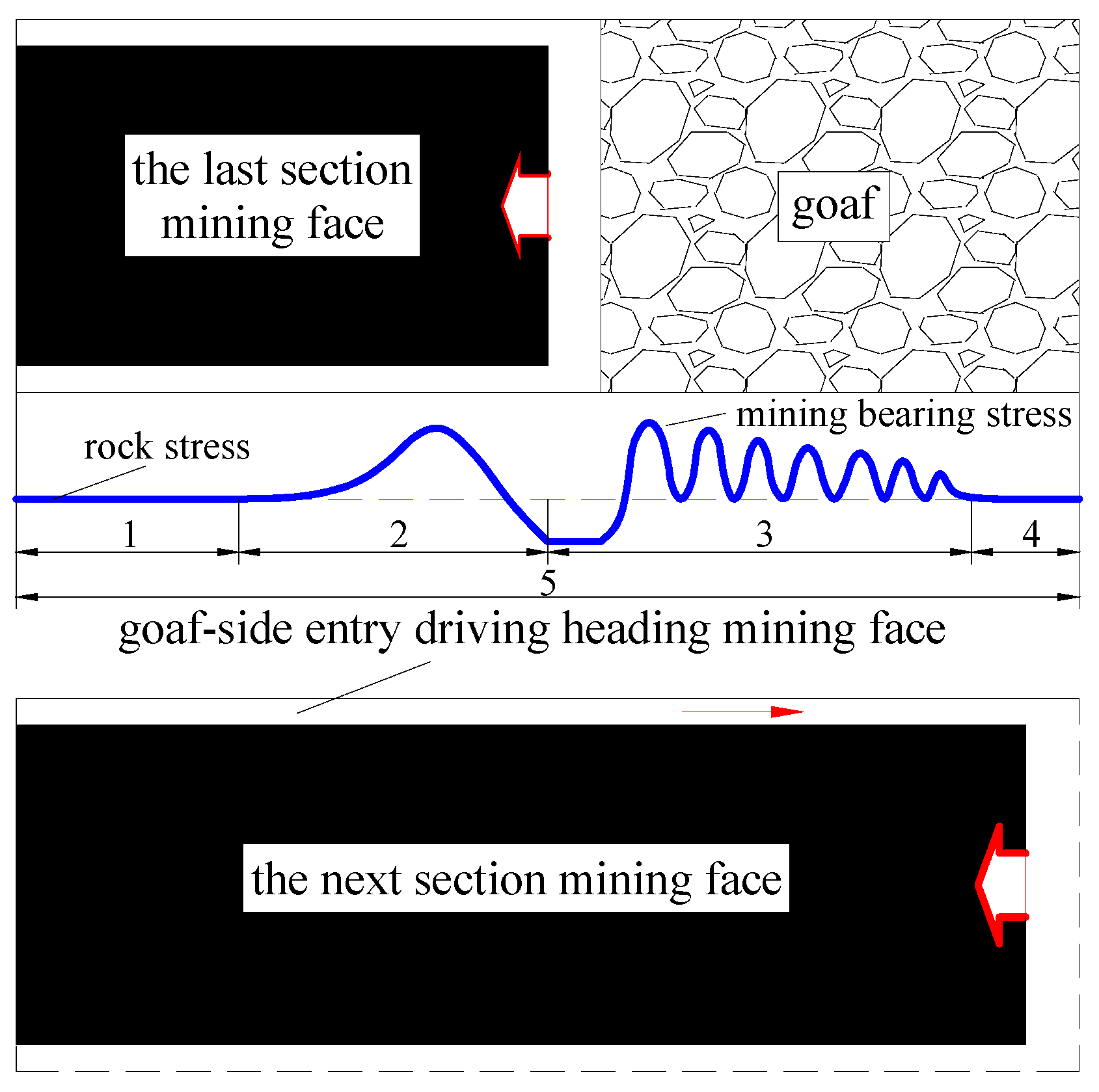
2. Subsection Stability Analysis of a Goaf-Side Entry Driving Heading Mining Face

The whole process of the goaf-side entry driving heading mining face is divided into the following five stages, as shown in Figure 1. In Figure 1, “1” is the stage of excavation in entity coal, “2” is the stage of advanced mining, “3” is the stage of hysteresis mining, “4” is the stage of goaf-side entry, and “5” is the stage of mining in this mining face.

2.1. The Stage of Excavation in Entity Coal

The roadway is driven in entity coal with the overlying rock strata not affected by mining. There is not much change in the external mechanical environment. The condition of the surrounding rock and stress environment is good, so it is easy to be maintained.

2.2. The Stage of Advanced Mining

Affected by advance bearing stress caused by mining on the last section of the mining face, the roadway stress is expanding, and the roadway deformation is growing with the approach of the last section of the mining face. However, the overlying rock strata structure remains stable as long as the proper support is applied. Then, the roadway surrounding rock stability can be ensured.

2.3. The Stage of Hysteresis Mining

With the meeting in the horizontal direction between the roadway and the last section of the mining face, the overlying rock strata structure will be adjusted massively, and the immediate roof behind the mining face will collapse irregularly. Correspondingly, the strata of the main roof will distort and sink, and then break up after the collapse of the downside immediate roof, and then it tends toward stability until one end of the main roof touches the gangue and is compacted. At last, it forms a bearing structure, consisting of blocks A, B, and C, as is shown in Figure 2 [34,35]. The aforementioned process decides the external environment of the goaf-side entry driving heading mining face. The roadway is below block B, and it suffers strong distortion pressure due to the slewing sinking of block B. The roof will show a deformation of several hundred millimeters. What is worse, the lithology of the roof is different and weak, which could easily lead to a roof fall accident. At this stage, the roadway stress environment deteriorates sharply and is difficult to maintain; thus, effective support measures must be taken to make it possible to keep the roadway surrounding rocks stable.

2.4. The Stage of Traditional Goaf-Side Entry

As the last section of the working face advances, the overlying rock strata structure in the goaf gradually stabilizes, and the roadway is excavated alongside the edge of the stable goaf. Although the roadway lies in the low section of lateral bearing stress, small stress concentrations may lead to a big deformation of the roadways surrounding rock, as the surrounding rocks are soft and broken. At this stage, when the roadway is excavated, the complete and timely support is a must, and the deformation of shallow surrounding rock is trying to be suppressed, so the stress state of the roadway surrounding rock is adapted to or improved.

2.5. The Stage of Mining in This Mining Face

Mining in this mining face leads to the increasing stress of the overlying rock strata structure and the breaking of the overlying rock strata in the goaf. The roadway is in front of this mining face: the overlying constraint condition between rocks will not change fundamentally and will keep the random balanced condition [36]. However, a certain degree of subsidence of the strata above the roadway is irresistible, which will lead to a larger deformation of the roadway. The roadway at this stage will be impacted by mining, so it is necessary to adapt to the sinking of the overlying rock strata, and furthermore, to strengthen supports to keep the roadway stable.

3. Confirmation of Coal Pillar Width

The coal pillar is an important part of the goaf-side entry driving heading mining face. Its stability decides that of the roadway to a large extent. Coal pillars with different widths can barely impact the activity and stability of the overlying rock, otherwise, the effect is big [36]. In general, with the expansion of coal pillar width, the stress concentration in the coal pillar changes from small to big, and finally stabilizes. Width that is too narrow will lead to pulling stress, making the coal pillar unstable; width that is too wide will lead to the concentration of stress and long-term rheology. With strong pressure in the goaf-side entry driving heading mining face, a narrow coal pillar will completely go into the plastic collapse condition and collapses towards the inside of the roadway and goaf. A limited increase of width will not fundamentally change this situation. The destruction of the coal pillar will impact the stability of the roadway, but it also speeds up the stabilizing process of the overlying rock structure, which fundamentally decreases the pressure of the roadway surrounding rock.

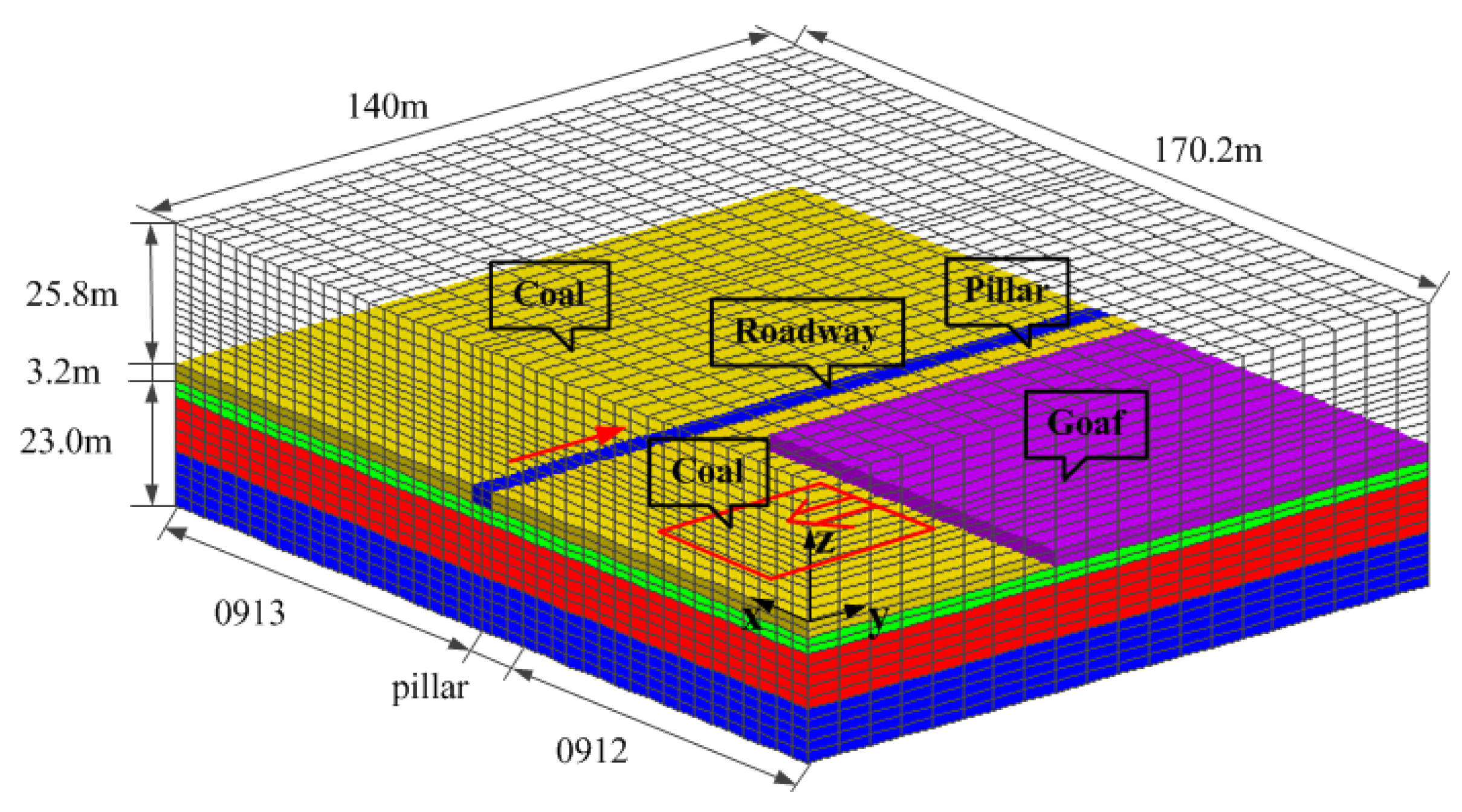
3.1. Numeric Calculation Model

Three-dimensional finite difference software FLAC3D was employed. We took the geological conditions of the 0931 mining face of a certain mine to build the numerical model. The model size: length × width × height = 170.2 m × 140 m × 52 m. There were 82,720 grids and 89,712 nodes. The upper surface of the model had stress boundaries with loads of 10.0MPa and simulates the dead weight of the overlying rock; the horizontal side stress coefficient was 1.2, with a load of 12.0 MPa. The model refers to Figure 3. Material constitutive model: the Moore–Coulomb model, and the mechanical parameters of rock in numerical simulation refer to Table 1. There were six calculation designs; the width of the coal pillar, which were 3 m, 4 m, 5 m, 6 m, 8 m, 10 m, respectively.
The surrounding rock stress and displacement features of the goaf-side entry driving heading mining face are periodic. The law of motion of overlying rock and the stability of the roadway are unique at different stages. The requirements of coal pillar width at different stages are not the same. Therefore, the width of the coal pillar was studied from three stages: (1) the stage of hysteresis mining; (2) the stage of goaf-side entry; (3) the stage of mining in this mining face. At the stages of excavation in entity coal and advanced mining, the overlying rock is stable, and the stability of the roadway has no direct relation with coal pillar width, so it was not specifically studied here.

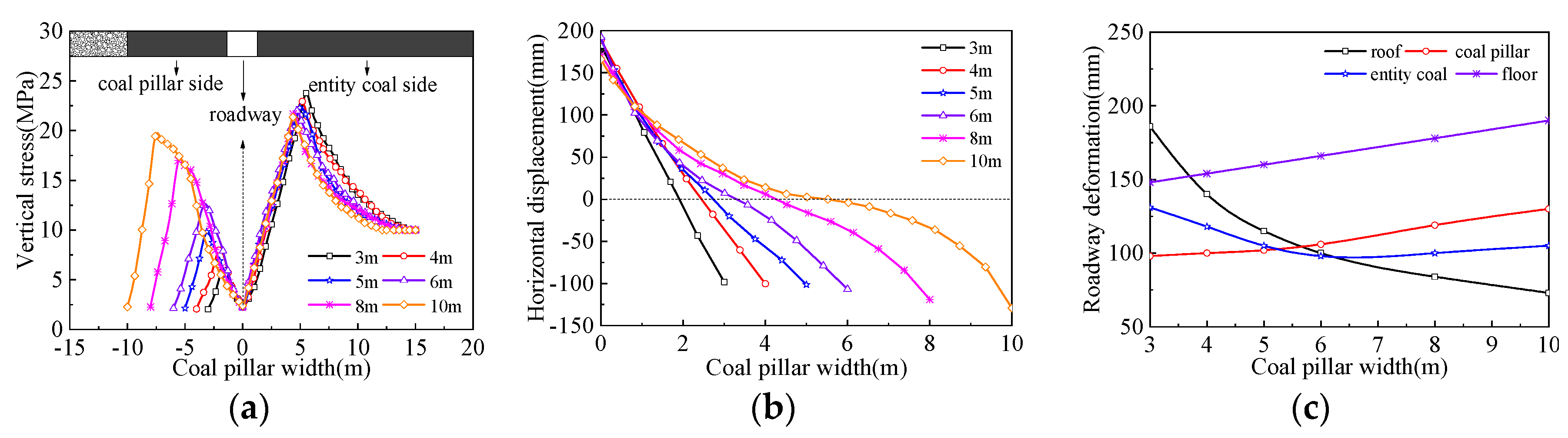
3.2. The Width of Coal Pillar at the Stage of Hysteresis Mining

The whole determination process from two aspects of stress and displacement is shown in Figure 4. It can be seen from Figure 4:
(1) With the increase of coal pillar width, the vertical stress distribution changes from triangle to irregular trapezoidal. The peak of vertical stress is increasing, and the position of the peak leans gradually to the goaf side. When the width of the coal pillar is 3.0–5.0 m, the coal pillar stress is lower than the original rock stress, then overall the coal pillar will go through plastic failure. When the width of the coal pillar is 6.0–8.0 m, there is a high stress section in the coal pillar, but it is just in a small scale, and then there will be a large section with plastic failure. When the width of the coal pillar is 10 m, there is a large section of high stress and the scale of plastic failure is small. The destruction spectrum of both sides of the coal pillar is 3.0–5.0 m. There is a weak correlation between the vertical stress of the entity coal side and the width of the coal pillar. When the coal pillar width increases from 3.0 m to 10 m, the peak of the vertical stress should be between 21.36 and 23.77 MPa. The position of the peak is 4.36–5.0 m away from the coal wall of the roadway.
(2) With the increase of coal pillar width, the displacement of the coal pillar towards the goaf side first increases and then decreases, but there is not much difference; the displacement towards the roadway appears to linearly increase. When the width of the coal pillar is 3.0–5.0 m, the displacement of the central coal pillar experiences a sharp change and there is no stable section. When the width of the coal pillar is 6.0–8.0 m, a small scale of stable areas began to form in the central coal pillar. When the width of the coal pillar is 10 m, although the stable areas are relatively large in the central coal pillar, the displacement towards the roadway increases obviously.
(3) The roof convergence decreases with the increase of coal pillar width. When the width of the coal pillar is 3.0–6.0 m, the roof convergence decreases sharply. When the width of the coal pillar is over 6 m, the sinking speed decreases remarkably and then gradually stabilizes; the amount of floor heave increases with the increase of the coal pillar width. The deformation of entity coal first decreases and then increases with the increasing width of the coal pillar, and it decreases the most when the coal pillar width is 6.0 m. The deformation of the coal pillar increases with the increasing coal pillar width. When the width of the coal pillar is 8.0–10 m, the deformation is over 3.0–6.0 m.
When the width of the coal pillar is 6.0–8.0 m at the stage of hysteresis mining, there are stable areas in the coal pillar with a relatively good stress environment. When the width of the coal pillar is 6.0 m, the condition of the roof convergence and the deformation of entity coal are obviously better than that between 8.0 and 10 m, and the displacement condition of surrounding rock is relatively good. Therefore, 6.0 m is a proper width of the coal pillar.

3.3. The Width of the Coal Pillar at the Stage of Goaf-Side Entry

Due to the limited length of the text, this thesis will not present the process of the stage of goaf-side entry and the stage of mining in this mining face, because the analyzing method is much like that of the stage of hysteresis mining, so there are only conclusions from them. The whole determination process is shown in Figure 5 and Figure 6.
When the width of the coal pillar is 5.0–6.0 m at the stage of goaf-side entry, there exists stable areas in the coal pillar with less stress concentration and a good environment of surrounding rock stress. When the width of the coal pillar is 5.0–6.0 m, the roof convergence and the deformation of entity coal are better than that between 3.0 and 4.0 m, and the amount of floor heave and the deformation of the coal pillar are obviously better than that between 8.0 and 10 m, and the displacement condition of the surrounding rock is relatively good. Therefore, 5.0–6.0 m is a proper width of the coal pillar.

3.4. The Width of the Coal Pillar at the Stage of Mining in this Mining Face

At the stage of mining in this mining face, when the width of the coal pillar is 6.0–8.0 m, there exists stable areas in the coal pillar with low levels of stress concentration and a relatively good environment for the surrounding rock stress. When the width of the coal pillar is 6.0–8.0 m, the condition of roof convergence is obviously better than that between 3.0 and 5.0 m, the condition of coal pillar deformation is better than that of 10 m, and the displacement condition of surrounding rocks is relatively good. Therefore, 6.0–8.0 m is a proper width of the coal pillar.

3.5. Proper Width of the Coal Pillar

Aggregate coal pillar width and key parameters of roadway stress and displacement at the aforementioned three stages are in Table 2.
In the transition from the stage of goaf-side entry to the stage of hysteresis mining, then to the stage of mining in this mining face, the coal pillar is consistently broken and crushed, which leads to decreasing stress concentration. Furthermore, the stress concentration of entity coal is growing, and the stress gradually transfers to the deep rock mess. When the coal pillar is too narrow, its load is very low. The coal pillar stress transfers to the entity coal in the process of the roadway deformation and the shallow rock mess cannot stand such high stress, so the stress then transfers gradually to the deep rock mess. When the coal pillar widens, its load increases, and its stress that is transferred to the entity coal decreases. Besides, the distance between the stress peak position of entity coal and the entity coal side also decreases a little compared with that of a narrow coal pillar. Taking coal pillar width and key parameters of surrounding rock stress and displacement at the aforementioned three stages into consideration, it can be concluded that when the width of a coal pillar is 6.0 m, the displacement and stress of the roadway are relatively small, and 6.0 m is a proper width of the coal pillar in the whole process of the goaf-side entry driving heading mining face.

4. Dynamic Underground Pressure Observation and Results

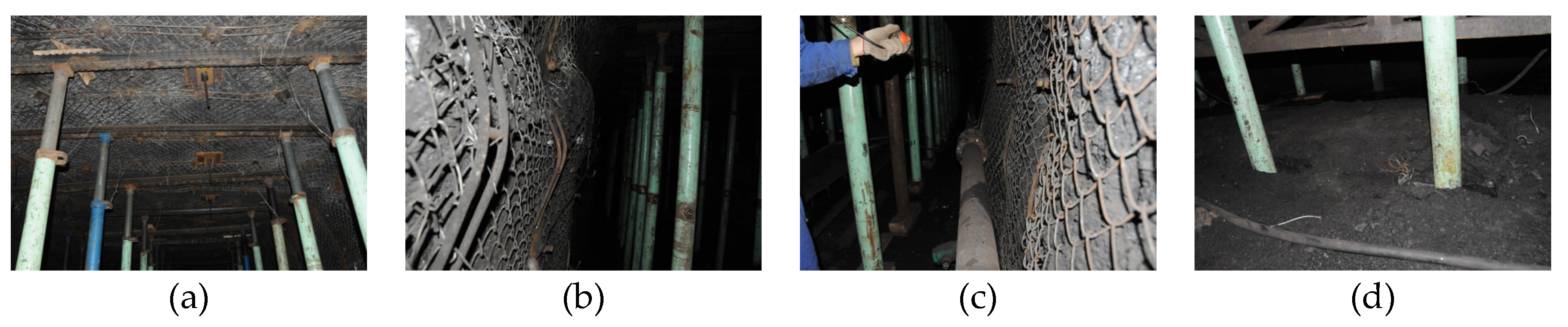
4.1. Project Profile

Some coal mines need to exploit coal seam 9# with a thickness of 3.32 m, a dip angle of 3°, and a burial depth of about 500 m. Its immediate roof is sandy mudstone, the main roof is kern stone, the immediate floor is carbon mudstone, and the main floor is sandy mudstone. The 0913 tailgate must finish excavation before completion of the mining of the 0912 mining face. The lithology of roof and floor of 9# coal seam and the roadway position relation are shown in Figure 7. The width of the coal pillar and the basic support parameters of the roadway can be determined through numerical calculation, and then regulate the excavation opportunity and support parameters at different stages on the basis of the dynamic underground pressure data. Basic support parameters are shown in Figure 8—both sides and the roof adopt a high-strength anchor of BHRB500, Φ20 mm and L2400 m, which is matched with an express rapid installation nut, aligning washer, disc steel pallet of 150 mm × 150 mm × 10 mm, rhombus metal net, and 14# rebar ladder beam, and the inter-row space of the sides and roof bolts are separately 800 mm × 800 mm and 900 mm × 800 mm. Two anchors of Φ18.9 mm and L7300 mm shall be arranged on the roof, which is matched with the disc steel pallet of 300 mm × 300 mm × 16 mm, aligning washer, lockset, and the inter-row space is 2400 mm × 2400 mm. In Figure 7, “1” is the 0913 headgate, “2” is the 0913 tailgate, “3” is the 0912 headgate, “4” is the 0912 tailgate, “5” is the stage of goaf-side entry, and “6” is the stage of the roadway driving towards the mining face along the goaf.

4.2. Underground Pressure Observation Scheme

4.2.1. Observation Station Layout

In order to master the underground pressure behavior during the whole process of the goaf-side entry driving heading mining face and dynamically regulate the excavation opportunity and support parameter of the whole roadway, the observation station shall be arranged by division into two phases.
(1) The first phase (the stage of heading mining). When the excavation place of the 0913 tailgate was 100 m from the 0912 mining face, the excavation would suspend, and the following six observation stations of P1, P2, P3, P4, P5, and P6 would be arranged with an interval of 10 m.
(2) The second phase (the stage of goaf-side entry). When the excavation face of the 0913 tailgate was behind about 200 m from the 0912 mining face, the excavation would restart, and six observation stations of P7, P8, P9, P10, P11, and P12 would be arranged going forwards with an interval of 50 m. The observation station layout is shown in Figure 9.

4.2.2. Displacement of the Roadway at the First Phase

The observation time lasted nearly 60 days and 780 data were acquired. The observed result is shown in Table 3, and the typical observation curve is shown in Figure 10.
It can be inferred from Figure 10 that the observation curve in the first phase can be divided into four periods: slow transformation period (beyond the range of 60 m at the front of the 0913 mining face), advanced mining influence period (within the range of 60 m at the front of the 0913 mining face), hysteresis mining influence period (within the range of 150 m at the rear of the 0913 mining face), and transformation stable phase (beyond the range of 150 m at the rear of the 0913 mining face). The monitor curve presents an “S” type—it increased slowly at the initial stage, and then accelerated gradually in an exponential form; after that, as the result of the function of negative feedback factors, the restriction factor of the system became stronger and stronger, which made the growth rate of the system decrease gradually after reaching the maximum value, and finally the functional value approached an asymptotic line. Further research discovers that the displacement of the roadway and the distance between the mining and excavation mining face presents a logistic function relationship:
y = a/[1+ek(xx0)].
In the equation: y is the displacement of the roadway; x is the distance between the mining and excavation mining faces; a, k, and x0 are the regression coefficients, and the specific parameters are shown in Table 4.

4.2.3. Displacement of the Roadway at the Second Phase

The observation time lasted nearly 40 days and 492 data were acquired. The observation results are shown in Table 5, and the typical observation curve is shown as Figure 11.
According to Figure 11, the observation curve of the second phase can be divided into two time periods: the period of excavation disturbance (within 0~150 m); the period of excavation stability (outside 150 m). Displacement of the roadway and the distance of roadway excavation basically present an exponential function relationship:
y = y0 + AeR0x.
In the equation: y is the displacement of the roadway; x is the excavation distance of the roadway; y0, A, and R0 are regression coefficients, and the specific parameters are shown in Table 6.

5. Dynamic Subsection Control Principle and Technology

5.1. Section Construction Time Determination

It can be known from Figure 10 that the influence range of bearing stress aroused by mining of the 0912 mining face was 60 m of the advancement mining face and 150 m of the hysteresis mining face; therefore, the 0913 tailgate should stop excavating when it was above 60 m of the 0912 mining face, the roof shall be steadily controlled by making use of the reinforced support measure, the excavation shall restart after falling behind the 0912 mining face of 150 m, and will experience the influence of strong dynamic pressure. Referring to Figure 11, in the range of the former 150 m of re-excavation, the deformation velocity of the roadway was larger and fluctuated ceaselessly, especially as there existed varying degrees of a rib spalling phenomenon on the coal pillar side, and it needed to strengthen the control to the coal pillar side.

5.2. Dynamic Subsection Control Principle

The dynamic subsection control principle of the goaf-side entry driving heading mining face is proposed on the basis of observation data analysis, namely “high resistance support, dynamic monitoring, subsection control, consolidation coal pillar side, stable control of roof”. The purpose is to improve the roadway surrounding rock stress, intensify the surrounding rock strength, enhance the self-carrying capacity of the surrounding rock, quicken the excavation speed of the roadway, and lower the maintenance cost of the roadway. The technical route is shown in Figure 12.

5.3. Dynamic Subsection Control Technology

The overall thought of the dynamic section control technology—the section support with bolt, anchor, net, and beam shall unite to offer strong support resistance. Grouting reinforcement was necessary for narrow pillars at key time frames; the single prop shall match with the π girder to strengthen the support of the roof. Support patterns and parameters are at different stages.
(1) The stage of excavation in entity coal. The stage of excavation in entity coal of the 0913 tailgate was about 150 m and located inside of the stopping line of the mining face, so the roadway can not be influenced by the mining and possessed a better stress environment; in addition, basic support parameters stated in Section 4.1 can be used.
(2) The stage of mining. It is known from Section 5.1 that the 0913 tailgate stopped excavation at the front of the 0912 mining face of about 60 m. A certain safety coefficient was left during the construction process—the 0913 tailgate stopped excavation at the front of the 0912 mining face of 100 m, and the already excavated roadway roof was supported by making use of a single hydraulic prop matched with the π girder. The roadway support intensity shall enlarge properly on the basis of basic support parameters—the inter-row space of the bolt was 700 × 700 mm, the row spacing of the anchor was adjusted as 1400 mm, and other parameters shall remain unchanged. Field observation found that roadway deformation mainly occurred on the roof and coal pillar side, the deformation of the entity coal side was relatively small, and the section can meet the locale production requirement after footwalling. The maintenance effect is shown in Figure 13.
(3) The stage of excavation disturbance. It is known from Section 5.1 that the 0913 tailgate should begin excavation when it lagged about 150 m from the 0912 mining face. A certain safety coefficient was left during construction, and the excavation should restart after it lagged 200 m from the 0912 mining face. The coal pillar in the range of the former 150 m of the restarted excavation had comparatively serious rib spalling; therefore, on the basis of the support parameter of the stage of mining, the roadway needed to have high water material grouting reinforcement. Meanwhile, ensure the coal pillar can be supported in a timely manner, and improve the pre-tightening force properly. Field observation found that the roof inclined to the coal pillar side, but the inclination degree was small, which explained that the coal pillar deformation was to be stable but still possessed certain carrying capacity.
(4) The stage of goaf-side entry. The deformation speed of the roadway tended to decrease and be stable after the 0913 tailgate re-excavated 150 m. The roadway support intensity needed to decrease properly, based on the basic support parameter in consideration of the construction progress and the cost of the roadway; the inter-row space of bolts was regulated as 900 mm × 900 mm, row spacing of the anchor was regulated as 2700 mm, and other parameters remained unchanged.

6. Conclusions

(1) There exists a significant difference between the goaf-side entry driving heading mining face and traditional goaf-side entry; the former one is influenced by the whole mining process on the last section of the mining face, and experiences a strong dynamic pressure function produced by the overlying rock structure, and the roadway support needs to guarantee the stability of the roof and the coal pillar under the rotation action of the overlying rock fracture. Meanwhile, the later one excavates along with the margin of stable goaf and locates at a lateral-bearing stress decreasing area without the influence of the overlying rock structure regulation, so the main task of the roadway support is to ensure the stability of the shallow surrounding rock structure.
(2) The stress and displacement feature of the goaf-side entry driving heading mining face had obvious stage properties, that was to say that both the motion law of the overlying rock structure and the stability of the roadway would be different at different stages. After comprehensive consideration of key parameters of roadway stress and displacement of the goaf-side entry driving heading mining face at different stages, it was found that both the displacement and stress of the roadway were small when the width of the coal pillar was 6.0 m, and it would be the reasonable coal pillar width. At this time, the economic and technical benefits are good.
(3) The dynamic underground pressure observation of the goaf-side entry driving heading mining face should be divided into two stages—the stage of heading mining, which consisted of 60 m of the advancement mining impact stage and 150 m of the hysteresis mining impact stage. Moreover, the roadway displacement and distance between excavation and the mining face was approximately a logistic function relationship: y = a/[1 + e−k(x − x0)]; the stage of goaf-side entry, which consisted of 150 m of an excavation disturbance period, and stability after the excavation period out of range of 150 m. In addition, the roadway displacement and roadway excavation distance approximately presented an exponential function relationship: y = y0 + AeR0x.
(4) The goaf-side entry driving heading mining face should stop excavation when it was about 60 m from the last section of the mining face, and restart excavation when it lagged more than 150 m from the last section of the mining face, based on which the dynamic subsection control principle was proposed with high resistance support, dynamic monitoring, subsection control, consolidation of the coal pillar side, stable control of the roof, and the dynamic subsection control technology of the section joint strong support was developed with bolt, anchor, net, and beam, grouting reinforcement of the coal pillar at key times, and reinforcement of the roof of the single prop shall match with the π girder. In this way, the distortion of the roadway was effectively controlled, and the mining excavation succession tension was eased.

Author Contributions

Y.Y. and J.B. conceived and designed the research; X.W. performed the numerical simulation and field tests; L.Z. provided theoretical guidance in the research process; Y.Y. analyzed the data and wrote the paper. All authors have read and agreed to the published version of the manuscript.

Funding

This research was funded by the National Nature Science Foundation of China, grant number No.51904269 and 51974269, and the Fifth “333 Project” Scientific Research Project of Jiangsu, China in 2019, grant number No. BRA2019236.

Conflicts of Interest

The authors declare no conflict of interest.

References

  1. Cai, W.Y.; Chang, Z.C.; Zhang, D.S.; Wang, X.F.; Cao, W.H.; Zhou, Y.Z. Roof filling control technology and application to mine roadway damage in small pit goaf. Int. J. Min. Sci. Technol. 2019, 29, 477–482. [Google Scholar] [CrossRef]
  2. Cheng, Y.H.; Bai, J.C.; Ma, Y.K.; Sun, J.; Liang, Y.P.; Jiang, F.X. Control Mechanism of Rock Burst in the Floor of Roadway Driven along Next Goaf in Thick Coal Seam with Large Obliquity Angle in Deep Well. Shock Vib. 2015. [Google Scholar] [CrossRef] [Green Version]
  3. Zheng, X.G.; Yao, Z.G.; Zhang, N. Stress distribution of coal pillar with gob-side entry driving in the process of excavation & mining. J. Min. Saf. Eng. 2012, 29, 459–465. [Google Scholar]
  4. Gao, F.Q.; Stead, D.; Kang, H.P.; Wu, Y.Z. Discrete element modelling of deformation and damage of a roadway driven along an unstable goaf—A case study. Int. J. Coal Geol. 2014, 127, 100–110. [Google Scholar] [CrossRef]
  5. Hou, C.J.; Li, X.H. Stability principle of large and small structure of surrounding rock in goaf-side entry of fully mechanized top coal caving. J. China Coal Soc. 2001, 26, 1–7. [Google Scholar]
  6. Kang, H.P.; Lin, J.; Fan, M.J. Investigation on support pattern of a coal mine roadway within soft rocks - a case study. Int. J. Coal Geol. 2015, 140, 31–40. [Google Scholar] [CrossRef]
  7. Qian, D.Y.; Zhang, N.; Shimada, H.; Wang, C.; Sasaoka, T.; Zhang, N.C. Stability of goaf-side entry driving in 800-m-deep island longwall coal face in underground coal mine. Arab. J. Geosci. 2016, 9, 82. [Google Scholar] [CrossRef]
  8. Wang, Q.; Gao, H.K.; Jiang, B.; Li, S.C.; He, M.C.; Wang, D.C.; Lu, W.; Qin, Q.; Gao, S.; Yu, H.C. Research on reasonable coal pillar width of roadway driven along goaf in deep mine. Arab. J. Geosci. 2017, 10, 466. [Google Scholar] [CrossRef]
  9. Xie, P.S.; Wu, Y.P. Deformation and Failure Mechanisms and Support Structure Technologies for Goaf-Side Entries in Steep Multiple Seam Mining Disturbances. Arch. Min. Sci. 2019, 64, 561–574. [Google Scholar]
  10. Zha, W.H. Reinforced Techniques Analysis of Goaf-Side Entry at Isolated Island Coal Face Based on FLAC Numerical Simulation. Adv. Mater. Res. 2012, 605–607, 210–214. [Google Scholar] [CrossRef]
  11. Liu, J.W.; Liu, C.Y.; Li, X.H. Determination of fracture location of double-sided directional fracturing pressure relief for hard roof of large upper goaf-side coal pillars. Energy Explor. Exploit. 2020, 38, 111–136. [Google Scholar] [CrossRef] [Green Version]
  12. Yu, Y.; Wang, X.; Bai, J.; Zhang, L.; Xia, H. Deformation Mechanism and Stability Control of Roadway Surrounding Rock with Compound Roof: Research and Applications. Energies 2020, 13, 1350. [Google Scholar] [CrossRef] [Green Version]
  13. Zhang, N.; Li, X.H.; Gao, M.S. Pretensioned support of roadway driven along next gob and heading adajacent advancing coal face and its application. Chin. J. Rock Mech. Eng. 2004, 23, 2100–2105. [Google Scholar]
  14. Zhang, Z.Z.; Wang, W.J.; Li, S.Q.; Bai, J.B.; Hao, S.P.; Wu, H.; Yu, X.Y. An Innovative Approach for Gob-Side Entry Retaining With Thick and Hard Roof: A Case Study. Teh. Vjesn. 2018, 25, 1028–1036. [Google Scholar]
  15. Kang, J.Z.; Shen, W.L.; Bai, J.B.; Yan, S.; Wang, X.Y.; Li, W.F.; Wang, R.F. Influence of abnormal stress under a residual bearing coal pillar on the stability of a mine entry. Int. J. Min. Sci. Technol. 2017, 27, 945–954. [Google Scholar] [CrossRef]
  16. Li, W.F.; Bai, J.B.; Cheng, J.Y.; Peng, S.; Liu, H.L. Determination of coal-rock interface strength by laboratory direct shear tests under constant normal load. Int. J. Rock Mech. Min. 2015, 77, 60–67. [Google Scholar] [CrossRef]
  17. Li, W.F.; Bai, J.B.; Peng, S.; Wang, X.Y.; Xu, Y. Numerical Modeling for Yield Pillar Design: A Case Study. Rock Mech. Rock Eng. 2015, 48, 305–318. [Google Scholar] [CrossRef]
  18. Shen, W.L.; Wang, X.Y.; Bai, J.B.; Li, W.F.; Yu, Y. Rock Stress Around Noncircular Tunnel: A New Simple Mathematical Method. Adv. Appl. Math. Mech. 2017, 9, 1330–1346. [Google Scholar] [CrossRef]
  19. Liu, J.H.; Cao, Y.Q.; Wei, Z.Q.; Shen, W. Research on reasonable width of partition pillar close to goaf heading mining in thick seam of deep shaft. Chin. J. Rock Mech. Eng. 2015, 34, 4271–4277. [Google Scholar]
  20. Zhang, G.C.; Wen, Z.J.; Liang, S.J.; Tan, Y.L.; Tian, L.; Zhao, Y.Q.; Zhao, D.S. Ground Response of a Gob-side Entry in a Longwall Panel Extracting 17 m-Thick Coal Seam: A Case Study. Rock Mech. Rock Eng. 2019, 53, 497–516. [Google Scholar] [CrossRef]
  21. Zhu, D.Y.; Gong, W.L.; Su, Y.; Guo, A.P. Application of High-Strength Lightweight Concrete in Gob-Side Entry Retaining in Inclined Coal Seam. Adv. Mater. Sci. Eng. 2020, 2020. [Google Scholar] [CrossRef] [Green Version]
  22. Chen, S.H.; Zhang, Z.H. Determination of Coal Pillar Width and Support Parameters in Deep Coal Mines—A Case Study. J. Test. Eval. 2019, 47, 3160–3173. [Google Scholar] [CrossRef]
  23. Shen, W.L.; Bai, J.B.; Wang, X.Y.; Yu, Y. Response and control technology for entry loaded by mining abutment stress of a thick hard roof. Int. J. Rock Mech. Min. 2016, 90, 26–34. [Google Scholar] [CrossRef]
  24. Wang, M.; Bai, J.B.; Li, W.F.; Wang, X.Y.; Cao, S.G. Failure mechanism and control of deep gob-side entry. Arab. J. Geosci. 2015, 8, 9117–9131. [Google Scholar] [CrossRef]
  25. Wang, M.; Bai, J.B.; Wang, X.Y.; Xu, Y.; Guo, Y.H.; Cao, J.L. The surrounding rock deformation rule and control technique of the roadway driven along goaf and heading for adjacent advancing coal face. J. Min. Saf. Eng. 2012, 29, 197–202. [Google Scholar]
  26. Wu, H.; Wang, X.K.; Wang, E.; Peng, G.; Zhang, Z.Z. Deformation characteristics and mechanism of deep subsize coal pillar of the tilted stratum. Energy Sci. Eng. 2020, 8. [Google Scholar] [CrossRef]
  27. Brodny, J.; Tutak, M. Analysing the Utilisation Effectiveness of Mining Machines Using Independent Data Acquisition Systems: A Case Study. Energies 2019, 12, 2505. [Google Scholar] [CrossRef] [Green Version]
  28. Prassetyo, S.H.; Irnawan, M.A.; Simangunsong, G.M.; Wattimena, R.K.; Arif, I.; Rai, M.A. New coal pillar strength formulae considering the effect of interface friction. Int. J. Rock Mech. Min. 2019, 123, 104102. [Google Scholar] [CrossRef]
  29. Recio-Gordo, D.; Jimenez, R. A probabilistic extension to the empirical ALPS and ARMPS systems for coal pillar design. Int. J. Rock Mech. Min. 2012, 52, 181–187. [Google Scholar] [CrossRef]
  30. Szurgacz, D.; Brodny, J. Tests of Geometry of the Powered Roof Support Section. Energies 2019, 12, 3945. [Google Scholar] [CrossRef] [Green Version]
  31. Trubetskoy, K.N.; Ruban, A.D.; Zaburdyaev, V.S. Characteristics of methane release in highly productive coal mines. J. Min. Sci. 2011, 47, 467–475. [Google Scholar] [CrossRef]
  32. Zhang, Z.Y.; Shimada, H.; Sasaoka, T.; Hamanaka, A. Stability Control of Retained Goaf-Side Gateroad under Different Roof Conditions in Deep Underground Y Type Longwall Mining. Sustainability 2017, 9, 1671. [Google Scholar] [CrossRef] [Green Version]
  33. Zolfaghari, A.; Bidar, A.S.; Javan, M.R.M.; Haftani, M.; Mehinrad, A. Evaluation of rock mass improvement due to cement grouting by Q-system at Bakhtiary dam site. Int. J. Rock Mech. Min. 2015, 74, 38–44. [Google Scholar] [CrossRef]
  34. Bai, J.B.; Hou, C.J.; Huang, H.F. Numerical simulation study on stability of narrow coal pillar of roadway driving along goaf. Chin. J. Rock Mech. Eng. 2004, 23, 3475–3479. [Google Scholar]
  35. Li, X.H. Study on the Stability of Surrounding Rock Structure of Gob Side Entry in Fully Mechanized Top Coal Caving. Ph.D. Thesis, China University of Mining and Technology, Xuzhou, China, 2000. [Google Scholar]
  36. Bai, J.B. Study on the Stability Principle and Control Technology of the Surrounding Rock of the Gob Side Entry in the Fully Mechanized Top Coal Caving. Ph.D. Thesis, China University of Mining and Technology, Xuzhou, China, 2002. [Google Scholar]
Figure 1. The schematic diagram of stages of a goaf-side entry driving heading mining face.
Sustainability 12 02623 g001
Figure 2. The bearing structure in the stage of hysteresis mining.
Sustainability 12 02623 g002
Figure 3. The numerical model.
Sustainability 12 02623 g003
Figure 4. The relationship between coal pillar width and stress and displacement of the roadway. (a) The vertical stress distribution; (b) the horizontal displacement distribution; (c) the deformation of the surrounding rock of the roadway (“+” means the displacement to gob side displacement, “−” means the displacement to the roadway).
Sustainability 12 02623 g004
Figure 5. The relationship between coal pillar width and stress and displacement of the roadway.
Sustainability 12 02623 g005
Figure 6. The relationship between coal pillar width and stress and displacement of the roadway.
Sustainability 12 02623 g006
Figure 7. The roof and floor lithology of 9# coal seam and roadway position relation.
Sustainability 12 02623 g007
Figure 8. Basic support parameters of the 0913 tailgate.
Sustainability 12 02623 g008
Figure 9. Observation station layout.
Sustainability 12 02623 g009
Figure 10. The displacement monitoring curve of the roadway in the first stage.
Sustainability 12 02623 g010
Figure 11. The displacement monitoring curve of the roadway in the second stage.
Sustainability 12 02623 g011
Figure 12. The technical route.
Sustainability 12 02623 g012
Figure 13. The maintenance effect of the roadway. (a) Roof; (b) coal pillar side; (c) entity coal side; (d) floor.
Sustainability 12 02623 g013
Table 1. The rock mechanical parameters.
LocationDensity
(kg/m3)
Bulk Modulus
(GPa)
Shear Modulus
(GPa)
Internal Friction Angle
(°)
Cohesion
(MPa)
Tensile Strength
(MPa)
Overlying rock25009.808.00345.502.10
Main roof25006.405.30283.301.90
Immediate roof25004.504.90273.101.70
9# coal seam14002.602.50201.201.30
Immediate floor25004.804.80282.901.68
Main floor26005.405.30283.351.89
Under rock25009.708.32335.402.06
Table 2. The key parameters at different stages.
StagePeak Stress PositionCoal Pillar Destruction Range
(m)
Range of Coal Pillar Width Appearing as a Stable Region
(m)
Coal Pillar Width with Small Roadway Deformation
(m)
Reasonable Coal Pillar Width at Different Stages
(m)
Proper Coal Pillar Width
(m)
Hysteresis miningCoal pillarTowards direction of goaf3.0–5.06.0–8.05.0–6.06.06.0
Entity coalDistance coal side 4.36–5.0 m
Goaf-side entry drivingCoal pillarCoal pillar central3.0–4.45.0–6.05.0–6.05.0–6.0
Entity coalDistance coal side 5.0–5.93 m
Mining in this working faceCoal pillarTowards direction of roadway3.0–5.26.0–8.06.0–8.06.0–8.0
Entity coalDistance coal side 5.4–6.48 m
Table 3. The deformation of the roadway at the first phase.
Measuring PointPeriod of Advanced MiningPeriod of Hysteresis MiningAccumulative Deformation of Roof and Floor
(mm)
Accumulative Deformation of Both Sides
(mm)
Affect Distance
(m)
Roof and Floor Convergence
(mm)
Both Sides Convergence
(mm)
Affect Distance
(m)
Roof and Floor Convergence
(mm)
Both Sides Convergence
(mm)
16021293150410346675505
263201101148398331658510
35819699151387321633488
464230110157409359692530
560220107159412323684500
65618880145369303601441
Table 4. The deformation of the roadway at the first phase.
Roadway NameObservation ContentRegression EquationCorrelation Coefficient
0913 tailgateRoof and floor convergencey = 671.2385/[1 + e−0.0274(x − 27.8481)]0.9978
Both sides convergencey = 516.8211/[1 + e−0.023(x − 48.151)]0.9983
Table 5. The deformation of the roadway at the first phase.
Measuring PointPeriod of Excavation DisturbancePeriod of Excavation StabilityAccumulative Deformation of Roof and Floor
(mm)
Accumulative Deformation of Both Sides
(mm)
Affect Distance
(m)
Roof and Floor Convergence
(mm)
Both Sides Convergence
(mm)
Affect Distance
(m)
Roof and Floor Convergence
(mm)
Both Sides Convergence
(mm)
1150131212>15056136218
2146139220>146713146233
3143125208>143813133221
4158140230>1581218152248
5152133219>15248137227
6151106189>15124108193
Table 6. The deformation of the roadway at the first phase.
Roadway NameObservation ContentRegression EquationCorrelation Coefficient
0913 tailgateRoof and floor convergencey = 156.0896 − 161.7491e−0.0119x0.9960
Both sides convergencey = 258.2091 − 270.9576e−0.0111x0.9920

