1. Introduction
Fiber reinforced polymer (FRP) composites were used in the construction of marine vessels and structures since the middle of the 20th century, whether it be as an exclusive option for construction [
1] or as a combination with traditional materials, such as steel [
2] or concrete [
3]. The design of these structures in aspects of strength, durability, and environmental influence on the mechanical properties was based mainly on experience for the best part of the said period. In the last couple of decades, significant effort was made to combine the experimental and scientific knowledge obtained so far in these field of research to enable prediction models that can be safely used to achieve sustainable and safe design of marine structures [
4,
5,
6,
7].
Mechanical properties of composite materials can be customized accordingly to specific applications demands by defining layup sequences, number of plies, and fiber orientation in the load direction [
8,
9,
10], which makes them appealing for design of marine structures with complex shapes. As the application field for marine composites widens, the request for resilience to mechanical loading and environmental influences rises. Adequate knowledge of limit state assessment, durability and life span, failure modes, fracture toughness, fire resistance, and environment influence parameters are crucial for an efficient and sustainable design process for structures in this demanding industry sector [
11].
The micromechanical aspect of composite materials design is often considered too complex and time-consuming for marine structural designers to deal with. The scientific research in this field of study should be aimed at simplifying the complex micromechanical level analysis and transform it into simple-to-use and time-saving engineering tools. The current practice for obtaining data for composites failure is based on experiments. As experiments can be relatively expensive and microscale data are usually unavailable to shipbuilders, they often turn to data and models prescribed by rules and procedures, thus leading to empirical based design process of marine structures. All of this yields rules that are very conservative in formulating design requests, which in turn hinders optimal design of marine structures concerning failure mechanisms.
One of the most important parameters influencing the mechanical properties of composite materials in marine applications is the absorption of seawater [
12]. Previous research on this matter is based on immersing test samples, called coupons, in laboratory conditions using accelerated procedures [
13] to simulate 20+ years of expected lifespan of typical marine structures [
14,
15]. The ageing of composites is usually carried out in climatic chambers in laboratory conditions [
6,
16,
17] to reduce the time of the test [
18,
19,
20,
21].
In addition, water absorption tests are often done with tap water, demineralized water, or artificial seawater [
22,
23]. This approach yields a lack of long-term data pertaining to degradation of mechanical properties exposed to the marine environment. Furthermore, the effects of the moving seawater (waves, sea level variations due to tides) and radically variant environmental effects that a typical marine vessel or structure are exposed to during their life cycle (vessels sailing all over the world, changes in salinity, climate) are not considered in accelerated ageing laboratory methods.
The absorption process of moisture and water of a composite exhibits complex behavior and dependence on various factors [
24], such as resin type and curing characteristics, void content, resin/fiber volume fractions [
25], the manufacturing technique, etc., [
26,
27,
28].
All this served as motivation to concentrate the research presented here on the influence of absorbed water on marine composites in real-life conditions, not laboratory, by submerging the coupons in the sea for prolonged periods of 6 and 12 months.
The dominant choice of composite materials in the civil sector of the marine vessels industries is glass fiber reinforced plastics (GRP), both for commercial and leisure vessels hulls [
29], resulting in a more cost-effective product. Classification societies can be somewhat restrictive when it comes to allowing composites as structural material. The choice of fibers is restricted to E-glass or carbon fibers, whilst resins are limited to epoxy, polyester, or vinyl-ester [
30,
31,
32].
The scope of the experimental research presented in this paper is the absorption of composite coupons in real sea environment and the assessment on the impact of the seawater on the mechanical properties of the material.
2. Materials and Methods
2.1. Materials
The ISO 527-4 [
33] standard prescribes the testing procedures for determination of tensile properties of fiber-reinforced plastic composites, both for unidirectional (UD) and multidirectional reinforcements.
In this paper, epoxy and polyester resins with glass fibers were used to manufacture standardized tensile testing coupons. Two matrix/fiber combinations were used, namely epoxy/glass and polyester/glass. The epoxy resin (Sicomin SR 8200 and SD 720 series hardener) and the polyester resin (Reichhold POLYLITE 507-574) mechanical properties are shown in
Table 1, as provided by the manufacturers of each component.
The fibers used in manufacturing the coupons are in the form of a UD stitched E-glass fiber fabric (Sicomin UDV600), with 594 g/m2 ply specific area weight.
Four different layup configurations were chosen for both matrix/fiber combinations to evaluate mechanical properties deterioration in the marine environment. The layup schematics are as follows, according to standard notation for composite layup [
34]:
Three rectangular plates measuring 300 × 450 mm with three different layup schemes UD0, 0/90, (0/45/90), were produced for each of the material combinations using 8 plies of the UD fabric per plate,
Figure 1. The epoxy/glass plates were produced by vacuum assisted infusion process, resulting in 3 + 0.2 mm thick plates. The infusion process proved problematic for the polyester resin as it was resulting in dry fibers on the tool surfaces, so the polyester/glass plates were finally produced by hand layup process, resulting in 5 ± 0.5 mm thick plates.
2.2. Coupons and Exposure to Marine Environment
Coupons measuring 250 mm in length and 25 mm in width [
33] were then cut out of the plates on a waterjet cutting machine (OMAX Maxiem series),
Figure 2. The cutting pressure was between 1400 and 3400 bar, with the average cutting speed of 1187 mm/min.
Waterjet cutting was chosen based on previous experience in cutting similar materials. The brittleness of glass and composite materials causes localized damage on the locations of first contact of the cutting high-pressure waterjet with the material. This enabled the precise positioning of the damage point on the coupon gauge length during the configuration of the waterjet machine. The intent here is to introduce a damage point, which is to simulate real damage on marine structures. This damage point represents a facilitated entry point of seawater in a real structure. Composite marine vessels and structures are usually protected by a final layer of gel coat that protects them from water penetration. When this protective layer is damaged during application, a more significant sea water intake rate in the structure material is enabled.
All the coupons were then weighed dry and measured with a ±0.1 mm accuracy.
The machined coupons were divided into 2 main groups by material combinations (epoxy/glass, polyester/glass), and in 3 subgroups according to the duration of exposure to the marine environment (dry, 6 months, 12 months). Each group consisted of 5 specimens (coupons); the first subgroup of coupons was not submerged but tested dry, to be used as a control group.
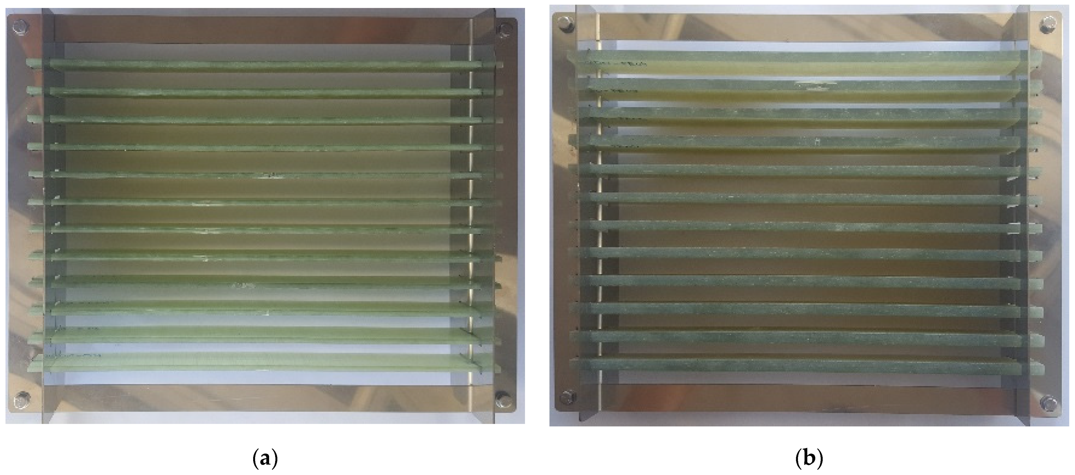
The other two subgroups were exposed to real-life sea environment, i.e., submerged into the sea on a depth of 10 m, at northern Adriatic in front of the city of Rijeka in Croatia for a duration of 6 and 12 months, respectively. The sea temperature at the location of experiment varies between 10–14 °C annually, salinity changes between 37.8–38.3 PPT, while the pH value is between 8.22–8.29 [
35]. The coupons were mounted on special stainless-steel frames (AISI 316L), shown in
Figure 3.
2.3. Testing Procedures
Each coupon was weighed with the same digital scale with a 200 g measuring range and 0.01 g resolution before (dry) and after the submerging time-period to determine the mass gain of the absorbed seawater. Wet coupons were taken out of the sea, cleaned from sea organisms accumulated during submersion with a soft brush, still submerged in seawater. Special care was taken not to damage the coupon. After cleaning, the coupons were left to drain, dried superficially with a cloth, and weighed all under one minute to assure minimal possible drying of the coupons.
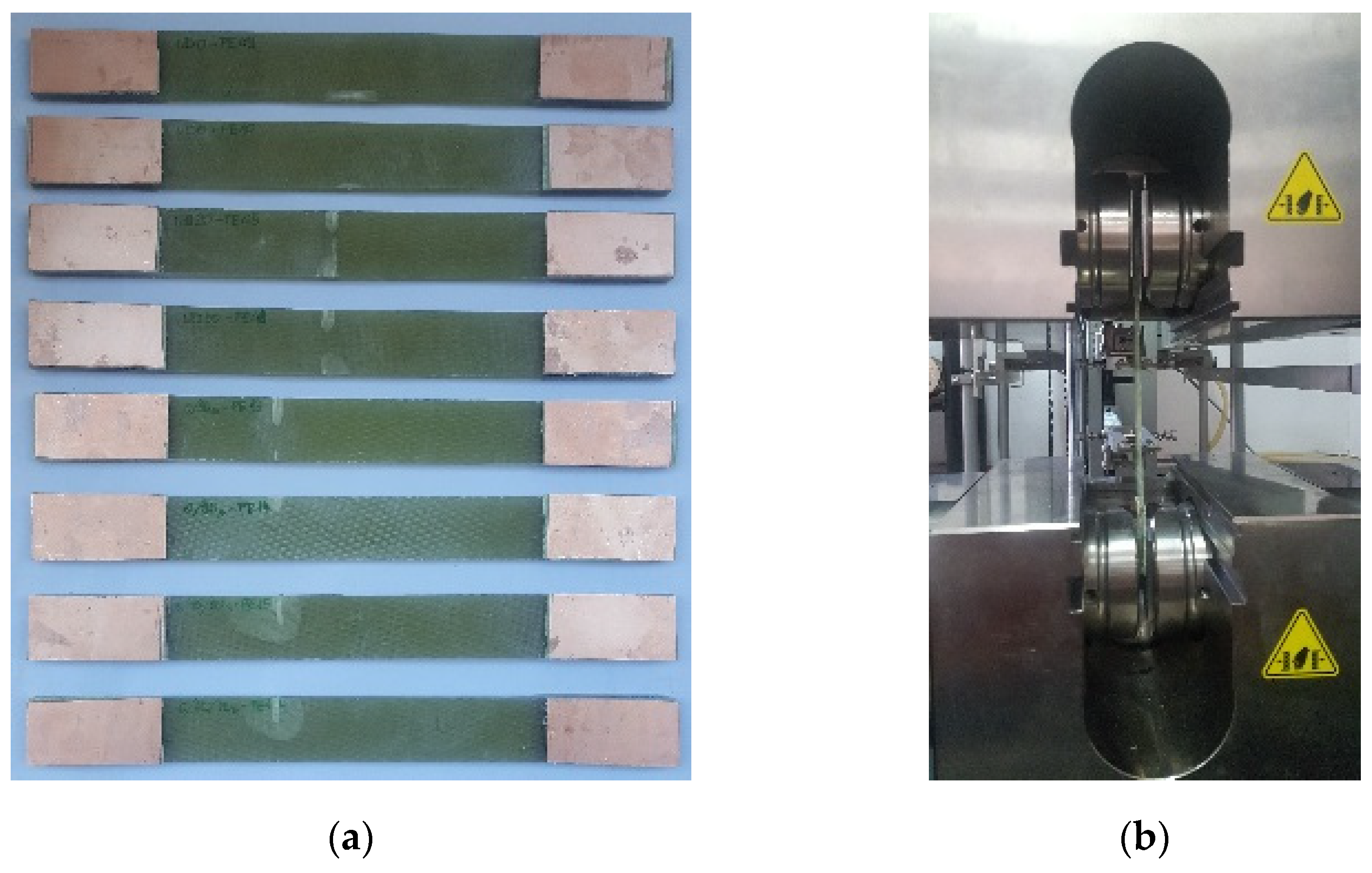
Reinforcement tabs, made of printed circuit board cutouts, were added at the coupon ends before the tensile test to minimize the influence of the grips pressure on the test results [
36]. The size of the tabs was chosen based on ISO 527-4 recommendations,
Figure 4.
Uniaxial tensile tests used for the determination of the material properties were performed on a Zwick 400 kN (ZwickRoell GmbH, Germany) universal testing machine. A macro extensometer was used to measure the specimens’ elongation. The displacement rate of the testing machine crosshead during testing was 2 mm/min.
Tensile testing was conducted in accordance with ISO 527 series standards recommendations.
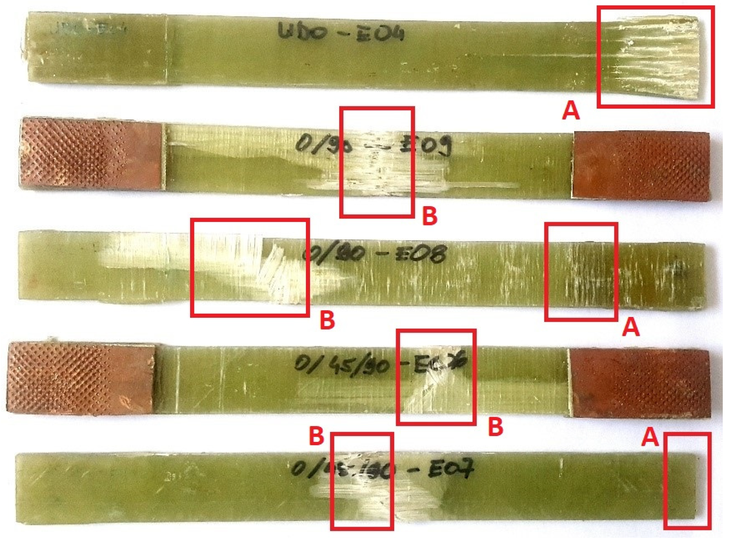
Microscopical investigation was performed on fractured coupons of three fiber layout configurations (UD0°, (0/90)s, (0/45/90)s) and for both dry coupons and coupons submerged in the sea for different periods i.e., 6 and 12 months. Surface and cross-sectional images were taken of all coupons, with special attention given to the grips areas (A) and locations with observed damage after the tensile test (B),
Figure 5.
Optical microscopy systems (Olympus SZX10 stereo optical microscope and Olympus BX51 SM optical microscope analysis system, both produced by Olympus corporation, Japan) and scanning electron microscope (SEM, FEI QUANTA 250 FEG, FEI Company, USA) with the OXFORD INSTRUMENTS PENTAFET, UK, Energy Dispersive Spectroscopy (EDS) analysis module were used to investigate the state of the coupon’s surfaces exposed to real sea environment and to identify changes in surface morphology caused by the exposure to seawater. Photographs were taken before and after the tensile tests.
3. Results
The results of the experimental investigation of epoxy/glass and polyester/glass coupons exposed to marine environment are presented in the form of diagrams, images, and tables. Experimental testing results shown here are comprised of coupon weight change (seawater absorption, algae growth) analysis, tensile strength determination, and surface morphology changes observations.
3.1. Algae and Marine Organisms Growth
The average aggregate mass gain due to the coupled algae/marine organisms’ growth and water absorption for the two matrix resins is given in
Table 2.
3.2. Water Absorption and Mass Change Analysis
The cleaned coupons’ mass measurement results after the period of 6 and 12 months of submersion are shown below,
Figure 6.
The minimum and maximum values of the mass gain for all layout configurations and material combinations are given in
Table 3 and
Table 4.
3.3. Tensile Test Results
The change in tensile strength due to the prolonged submersion in seawater is shown in
Figure 13 and
Figure 14.
3.4. Microscopical Investigation
Surface and cross-sectional images obtained by optical microscopy are not presented here but are available in a publicly accessible repository to save paper space and keep the readers focus on the more detailed and more illustrative SEM results.
4. Discussion
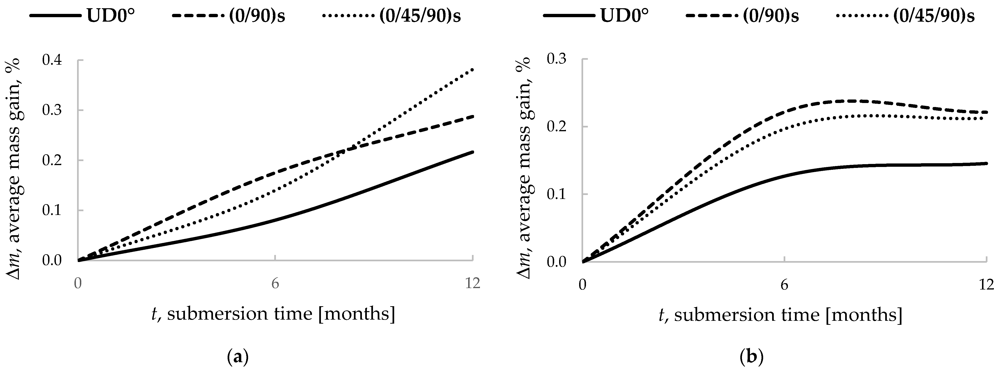
The mass measurement of all coupons before and after the submersion showed an increase of mass for all coupons,
Table 3 and
Table 4,
Figure 6. The epoxy resin coupons showed a greater average mass gain due to water absorption compared to polyester ones. Of the total of six resin material/fiber layout configurations, epoxy coupons with (0/90)s layout and all of the polyester coupons showed signs of water absorption saturation in the one year period. The epoxy UD0° and (0/45/90)s fiber layout have still and rising mass gain curve, indicating that water absorption saturation was not achieved after one year of submersion,
Figure 6a. The (0/45/90)s fiber layout configuration coupons for both resin types showed the greatest mass gain compared to that of the other fiber layout configurations.
Polyester matrix coupons amassed more microbial growth than the epoxy ones. This emphasizes the importance of the application of real sea environment instead of, in similar research, more commonly used artificial sea and environmental conditions generated in a laboratory.
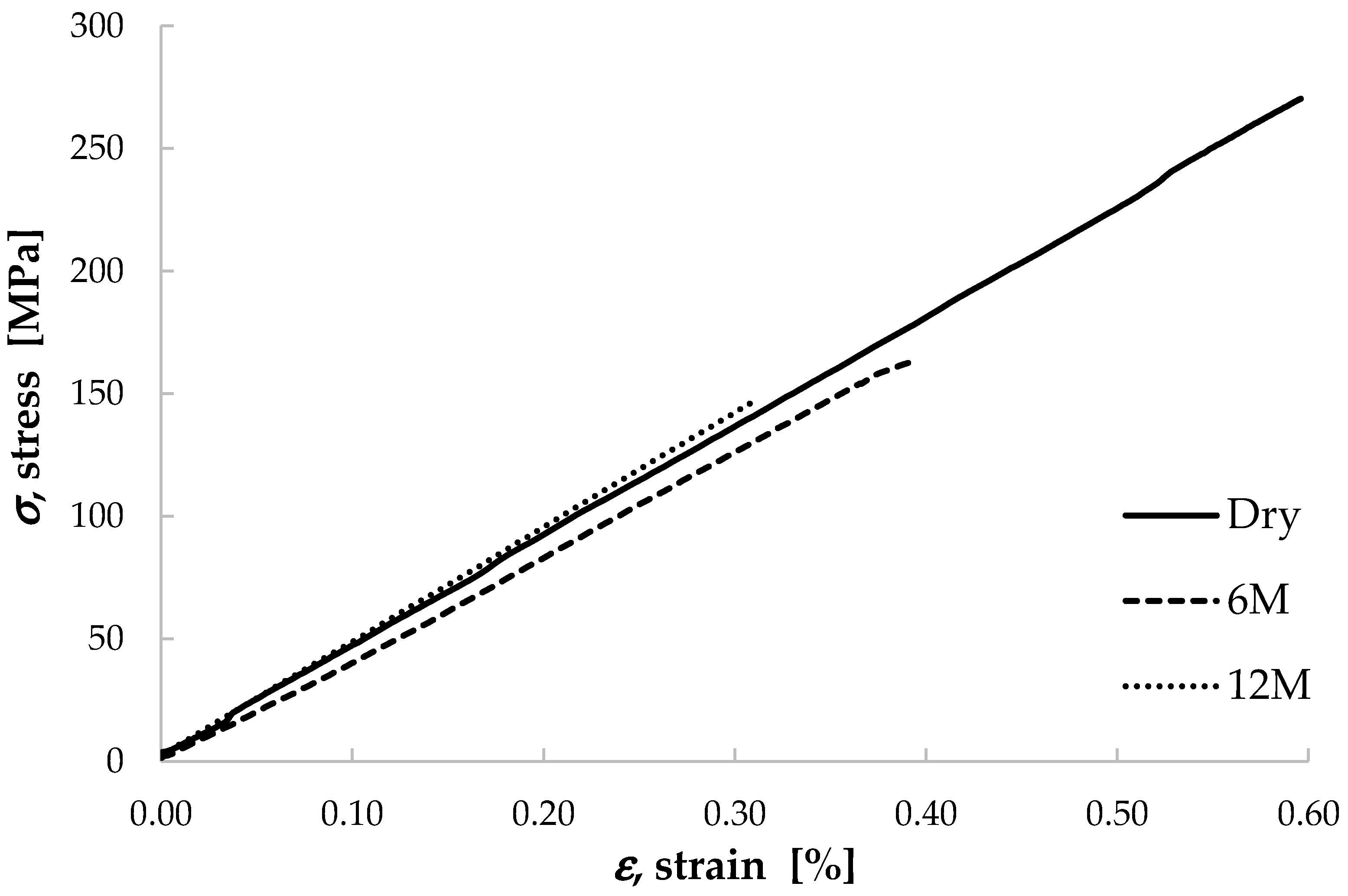
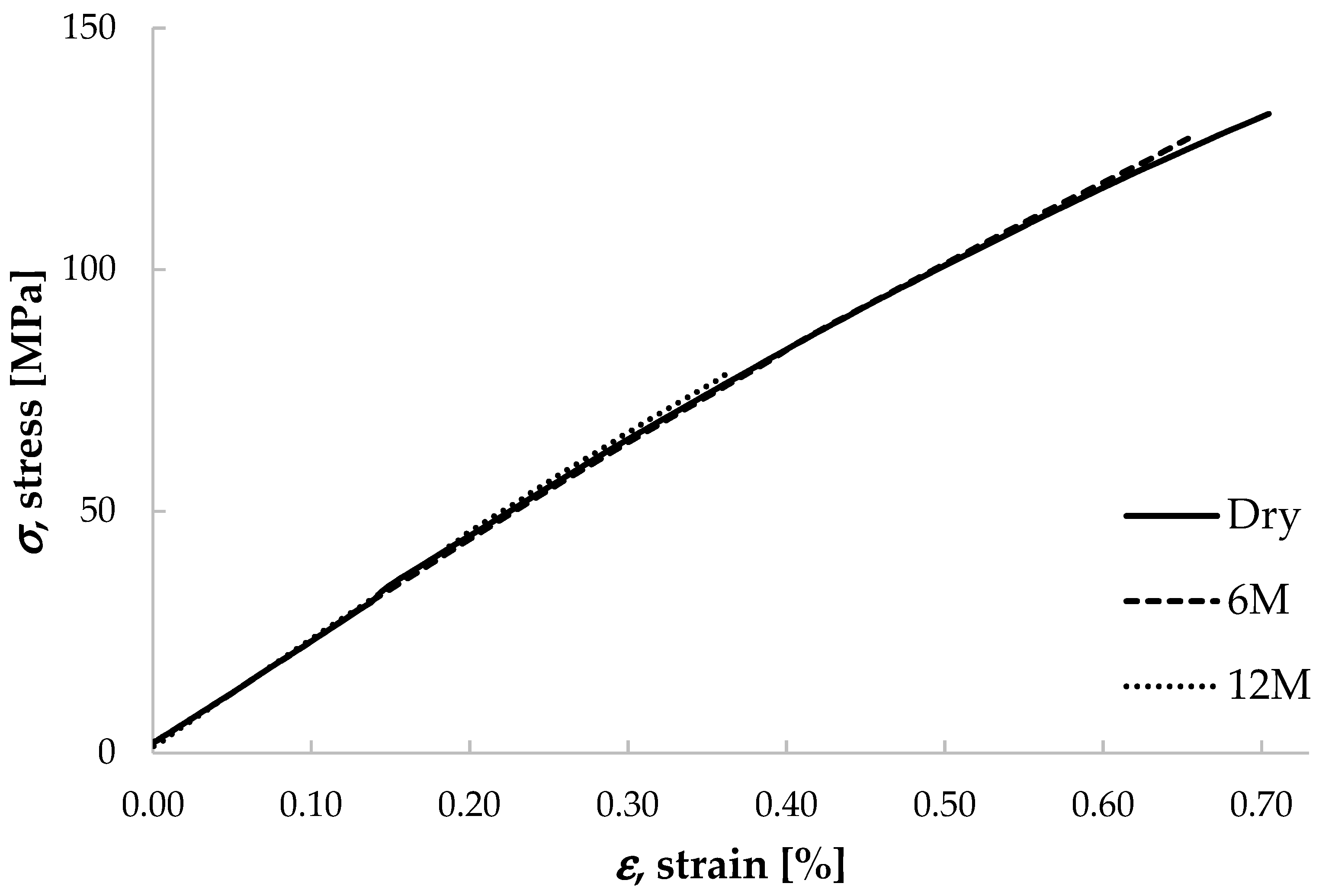
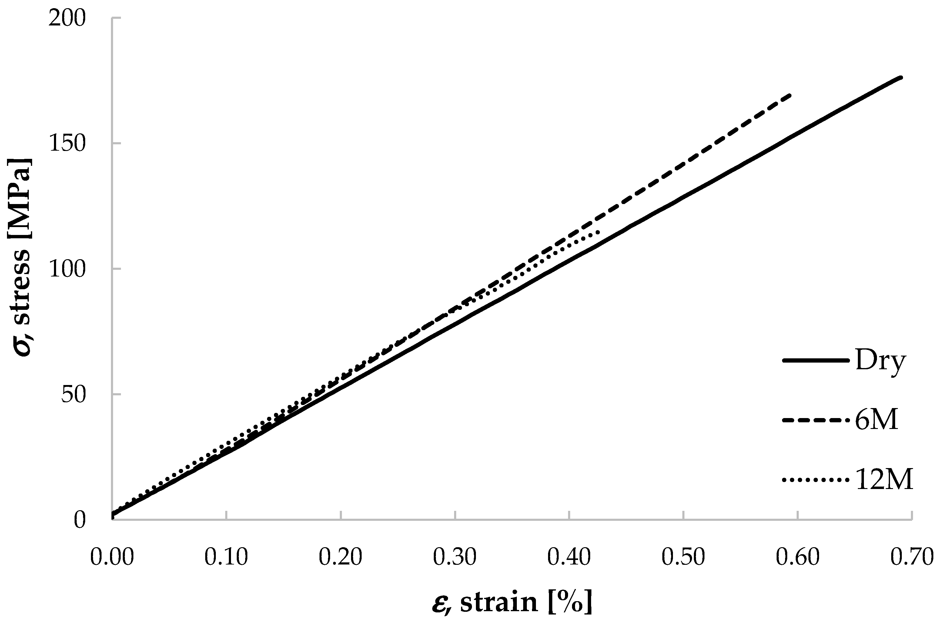
In all the diagrams in
Figure 7,
Figure 8,
Figure 9,
Figure 10,
Figure 11 and
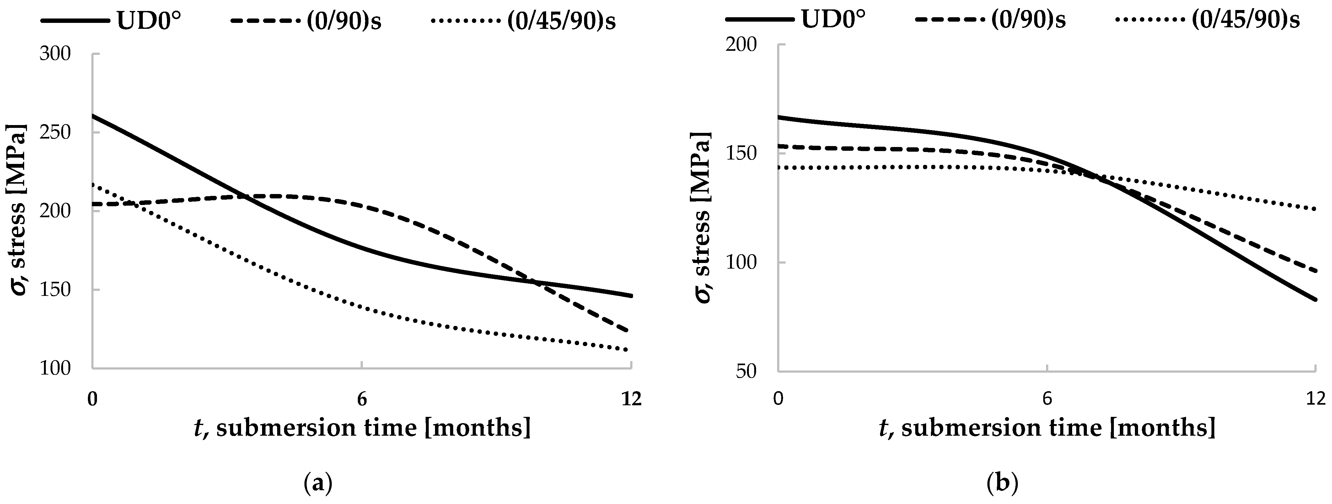
Figure 12, the reference stress-strain curve is designated as “Dry”. This curve represents the tensile mechanical properties of coupons not exposed to seawater. All submerged specimens had reduced tensile strength on average. Polyester resin coupons had a more pronounced drop in strength in the period form the 6th to the 12th month,
Figure 13b, while the epoxy resin coupons exhibited greater tensile strength loss after the first 6 months of submersion. The only exception of this behavior was noticed in the epoxy coupons with the (0/90)s fiber layout configuration,
Figure 14a. This is to be attributed to a single specimen from the group of this material and fiber layout combination submerged in the sea for 6 months exhibiting “extreme” tensile strength. By further examination, a higher fiber content in the said specimen was identified compared to that of the other specimens from the same group. This demonstrates that the manufacturing process has a strong impact on the mechanical properties of the finalized composite part.
Importantly, the environmental conditions (sea temperature, currents, sea level etc.) were not constant as they would be in a laboratory-based environment. The first 6 months of submersion spanned from late autumn to early summer i.e., predominantly colder environmental conditions. Subsequently, the next 6 months were predominantly warmer.
The results obtained in this research correlate with that of previous research by other researchers (pp. 129–142 in [
5]) [
37,
38,
39]. The novelty of this research is the exposure to real sea environment with all the environmental and sea living organisms’ effects acting simultaneously and randomly on the materials during the submersion, as opposed to, more commonly, artificial and laboratory conditions, often combined with accelerated absorption tests.
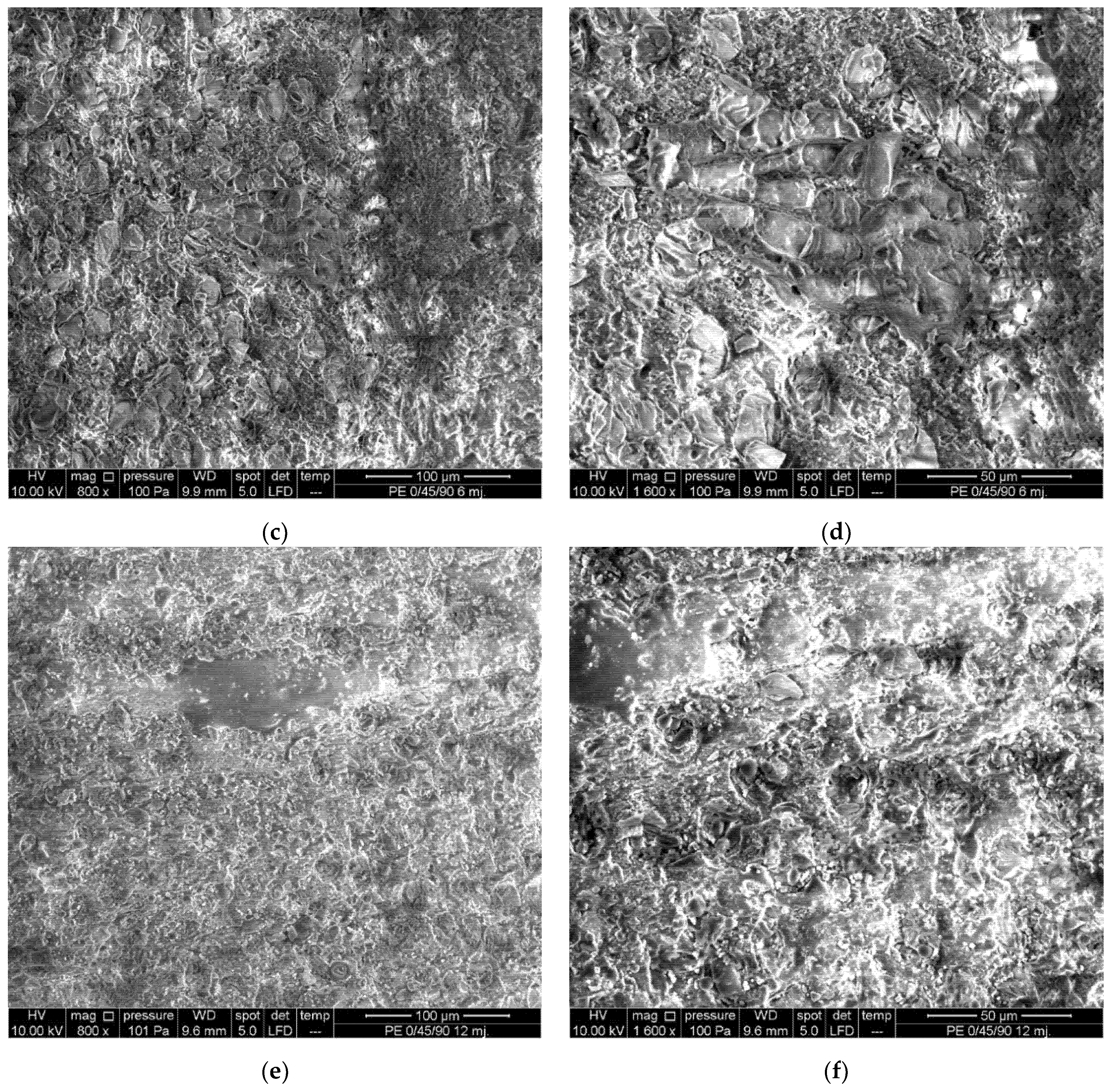
Analysis of the images collected during the microscopical investigation showed formation of salt crystals on the surface layers of the coupon as well as embedded salt crystals in both resins. The epoxy resin coupons showed a greater accumulation of salt crystals,
Figure 14c,
Figure 15e and
Figure 16c, than polyester ones,
Figure 17c,
Figure 18d and
Figure 19d, regardless of the fiber orientation setups.
One additional phenomenon noticed was the attachment and growth of marine microorganism on the organic resins used as matrix materials. The attachment and growth of sea microorganisms on the surface of the coupons was more intense in the first 6 months for the epoxy matrix coupons, but the total growth and maximum values after 12 months were more significant for the polyester ones, causing significant morphological changes in the resin,
Figure 17e,
Figure 18d and
Figure 19f. The (0/45/90)s fiber configuration attracted the most microorganisms for the epoxy resin coupons,
Figure 16e,f, while for the polyester ones, most organism were found in the (0/90)s configuration,
Figure 18c,d. The algae attached to the surface of the coupons were easily removable during the cleaning of the coupons and did not leave any noticeable macroscopic damage areas on the coupons.
However, the microorganisms that settled on the coupon’s matrix were causing mechanical changes on the organic resin [
40], effectively creating voids from the surface and into the matrix; hence, additionally changing the mechanical properties of the composite. Since the polyester coupons were manufactured by hand layup, the number of imperfections and voids in the matrix was greater than in that of the vacuum-infused epoxy coupons. This resulted in a greater number of favorable locations for the development of microorganisms, and therefore, a greater influence on the mechanical properties of the composite material.
5. Conclusions
Considerable effects of the real sea environment on composite materials were noticed in the form of reduced mechanical strength for the tested coupons submerged in the sea. The submerged UD0, (0/90)s, and (0/45/90)s epoxy/glass coupons exhibited tensile strength reduction of 32%, 14%, and 36% after 6 months of submersion (with the exception of one inadequately manufactured (0/90)s coupon), whilst 44%, 40%, and 49% after 12 months of submersion, respectively. The polyester/glass UD0, (0/90)s, and (0/45/90)s coupons have lost 11%, 5%, and 1% after 6 months of submersion, and 50%, 37%, and 13% after 12 months in the sea. The (0/45/90)s layout configuration for the polyester/glass combination showed the greatest resilience to the marine environment. However, further study is needed here because the polyester coupons were made by hand-layup process, which can significantly affect mechanical characteristics of the composite. This issue will be examined more in detail when the currently submerged 24-month coupons batch is extracted from the sea.
The growth of microorganisms embedded in the resin and invertebrate (Nematoda) organism attached to the surface of the coupons effectively created voids in the matrix resin and produced a direct effect on mechanical properties. As microorganisms are only able to accelerate chemophysical erosion of the plastic surfaces in marine environment, probably through the secretion of corrosive substance (acids, hydrolytic catalyzers etc.), further in-depth research on this effect is necessary.
The findings of the research indicate the importance of biofouling in environmental degradation of mechanical properties of composite materials in the marine environment. Ageing of FRP composites in real-time and real marine environment differs with the more commonly used accelerated ageing methods due to the effects of the marine organisms attached to the material. This can affect the accuracy of results obtained by the artificial environment and accelerated testing methodology if sufficient care is not taken to assure the replication of real marine environment and its effects.
More data from longer exposure are needed to enable the development of a reliable predictive numerical model of the mechanical behavior of composite materials exposed to real sea environment, which would represent a basic tool to assess the durability and the sustainability of composite marine structures during their exploitation. Additional coupons were already submerged in the sea to ensure the continuation of this research. This additional set of data will help in building predictive numerical model that could successfully replace the time and resource consuming experiments. However, stochastic nature of the environmental loading must be incorporated in that model. For that reason, placing coupons in different types of marine environment (regarding the temperature, sa-linity, pH value, etc.) would bring even better accuracy of the numerical model. Also, when it comes to use of composites in marine industry, it would be beneficial to place the test coupons in different locations to account for change in the structure of micro-organisms due to ballast water discharge. This is the path that should be followed in future research.
Sustainability of composites in general in the marine industry was often emphasized in terms suggesting that composite materials offer the possibility of building lighter vessels that can carry more cargo and/or produce lower emissions, with the expansion of the maintenance intervals [
41]. However, potential sustainability needs to be validated, since different types of composites react differently when exposed to harsh marine environment. This study presents a step in that direction giving insight into the behavior and change of mechanical properties for specific type of composites exposed for prolonged periods to the real marine environment.
Supplementary Materials
The complete set of SEM images obtained during this research is available on Vizentin, Goran (2021), “Marine Composites SEM”, Mendeley Data, V1, doi:10.17632/j8tvmkpmwf.1.
Author Contributions
Conceptualization, G.V.; methodology, G.V.; validation, G.V., D.G. and V.Š.; formal analysis, G.V.; investigation, G.V., D.G. and V.Š.; writing—original draft preparation, G.V.; writing—review and editing, D.G. and V.Š. All authors have read and agreed to the published version of the manuscript.
Funding
This research was funded by University of Rijeka under the project number uniri-technic-18-200 “Failure analysis of materials in marine environment”.
Institutional Review Board Statement
Not applicable.
Informed Consent Statement
Not applicable.
Conflicts of Interest
The authors declare no conflict of interest. The funders had no role in the design of the study; in the collection, analyses, or interpretation of data; in the writing of the manuscript, or in the decision to publish the results.
References
- Cejuela, E.; Negro, V.; del Campo, J.M. Evaluation and Optimization of the Life Cycle in Maritime Works. Sustainability 2020, 12, 4524. [Google Scholar] [CrossRef]
- Tang, Y.; Sun, Z.; Wu, G. Compressive Behavior of Sustainable Steel-FRP Composite Bars with Different Slenderness Ratios. Sustainability 2019, 11, 1118. [Google Scholar] [CrossRef] [Green Version]
- Mahdavi, G.; Nasrollahzadeh, K.; Hariri-Ardebili, M.A. Optimal FRP Jacket Placement in RC Frame Structures towards a Resilient Seismic Design. Sustainability 2019, 11, 6985. [Google Scholar] [CrossRef] [Green Version]
- Pritchard, G. Reinforced Plastics Durability; Woodhead Publishing Limited: Cambridge, UK, 1999. [Google Scholar]
- Davies, P.; Rajapakse, Y.D.S. (Eds.) Durability of Composites in a Marine Environment; Solid Mechanics and Its Applications; Springer: Dordrecht, The Netherlands, 2014; Volume 208. [Google Scholar]
- Davies, P.; Rajapakse, Y.D.S. (Eds.) Durability of Composites in a Marine Environment 2; Solid Mechanics and Its Applications; Springer International Publishing: Cham, Switzerland, 2018; Volume 245, ISBN 978-3-319-65144-6. [Google Scholar]
- Martin, R. Ageing of Composites; Woodhead Publishing Limited: Cambridge, UK, 2008. [Google Scholar]
- Irez, A.B.; Zambelis, G.; Bayraktar, E. A New Design of Recycled Ethylene Propylene Diene Monomer Rubber Modified Epoxy Based Composites Reinforced with Alumina Fiber: Fracture Behavior and Damage Analyses. Materials 2019, 12, 2729. [Google Scholar] [CrossRef] [PubMed] [Green Version]
- İREZ, A.B.; Bayraktar, E. Design of Epoxy Modified Recycled Rubber-Based Composites: Effects of Different Contents of Nano-Silica, Alumina and Graphene Nanoplatelets Modification on the Toughening Behavior. GAZI Univ. J. Sci. 2020, 33, 188–199. [Google Scholar] [CrossRef]
- Danilova, S.N.; Yarusova, S.B.; Kulchin, Y.N.; Zhevtun, I.G.; Buravlev, I.Y.; Okhlopkova, A.A.; Gordienko, P.S.; Subbotin, E.P. UHMWPE/CaSiO3 Nanocomposite: Mechanical and Tribological Properties. Polymers 2021, 13, 570. [Google Scholar] [CrossRef]
- Barsotti, B.; Gaiotti, M.; Rizzo, C.M. Recent Industrial Developments of Marine Composites Limit States and Design Approaches on Strength. J. Mar. Sci. Appl. 2020, 19, 553–566. [Google Scholar] [CrossRef]
- Vizentin, G.; Vukelic, G. Degradation and Damage of Composite Materials in Marine Environment. Medziagotyra 2019, 26, 337–342. [Google Scholar] [CrossRef] [Green Version]
- Morla, P.; Gupta, R.; Azarsa, P.; Sharma, A. Corrosion Evaluation of Geopolymer Concrete Made with Fly Ash and Bottom Ash. Sustainability 2021, 13, 398. [Google Scholar] [CrossRef]
- Bond, D.A. Moisture Diffusion in a Fiber-Reinforced Composite: Part I—Non-Fickian Transport and the Effect of Fiber Spatial Distribution. J. Compos. Mater. 2005, 39, 2113–2142. [Google Scholar] [CrossRef]
- Eftekhari, M.; Fatemi, A. Tensile Behavior of Thermoplastic Composites Including Temperature, Moisture, and Hygrothermal Effects. Polym. Test. 2016, 51, 151–164. [Google Scholar] [CrossRef]
- Ounaies, M.; Harchay, M.; Dammak, F.; Daly, H. Ben Prediction of Hygrothermal Behavior of Polyester/Glass Fiber Composite in Dissymmetric Absorption. J. Compos. Mater. 2018, 52, 4001–4007. [Google Scholar] [CrossRef] [Green Version]
- Bank, L.C.; Gentry, T.R.; Barkatt, A. Accelerated Test Methods to Determine the Long-Term Behavior of FRP Composite Structures: Environmental Effects. J. Reinf. Plast. Compos. 1995, 14, 559–587. [Google Scholar] [CrossRef]
- Davies, P. Towards More Representative Accelerated Aging of Marine Composites. In Advances in Thick Section Composite and Sandwich Structures; Springer International Publishing: Cham, Switzerland, 2020; pp. 507–527. [Google Scholar]
- de Souza Rios, A.; de Amorim, W.F.; de Moura, E.P.; de Deus, E.P.; de Andrade Feitosa, J.P. Effects of Accelerated Aging on Mechanical, Thermal and Morphological Behavior of Polyurethane/Epoxy/Fiberglass Composites. Polym. Test. 2016, 50, 152–163. [Google Scholar] [CrossRef]
- Cysne Barbosa, A.P.; Fulco, A.P.P.; Guerra, E.S.; Arakaki, F.K.; Tosatto, M.; Costa, M.C.B.; Melo, J.D.D. Accelerated Aging Effects on Carbon Fiber/Epoxy Composites. Compos. Part B Eng. 2017, 110, 298–306. [Google Scholar] [CrossRef]
- Panaitescu, I.; Koch, T.; Archodoulaki, V.-M. Accelerated Aging of a Glass Fiber/Polyurethane Composite for Automotive Applications. Polym. Test. 2019, 74, 245–256. [Google Scholar] [CrossRef]
- Helbling, C.S.; Karbhari, V.M. Investigation of the Sorption and Tensile Response of Pultruded E-Glass/Vinylester Composites Subjected to Hygrothermal Exposure and Sustained Strain. J. Reinf. Plast. Compos. 2008, 27, 613–638. [Google Scholar] [CrossRef]
- Bian, L.; Xiao, J.; Zeng, J.; Xing, S. Effects of Seawater Immersion on Water Absorption and Mechanical Properties of GFRP Composites. J. Compos. Mater. 2012, 46, 3151–3162. [Google Scholar] [CrossRef]
- Mayya, H.B.; Pai, D.; Kini, V.M.; Padmaraj, N.H. Effect of Marine Environmental Conditions on Physical and Mechanical Properties of Fiber-Reinforced Composites—A Review. J. Inst. Eng. Ser. C 2021, 102, 843–849. [Google Scholar] [CrossRef]
- Joliff, Y.; Belec, L.; Chailan, J.F. Modified Water Diffusion Kinetics in an Unidirectional Glass/Fibre Composite Due to the Interphase Area: Experimental, Analytical and Numerical Approach. Compos. Struct. 2013, 97, 296–303. [Google Scholar] [CrossRef]
- Gellert, E.P.; Turley, D.M. Seawater Immersion Ageing of Glass-Fibre Reinforced Polymer Laminates for Marine Applications. Compos. Part A Appl. Sci. Manuf. 1999, 30, 1259–1265. [Google Scholar] [CrossRef]
- Vailati, M.; Mercuri, M.; Angiolilli, M.; Gregori, A. Natural-Fibrous Lime-Based Mortar for the Rapid Retrofitting of Masonry Heritage. Preprints 2021. [Google Scholar] [CrossRef]
- Fan, Y.; Gomez, A.; Ferraro, S.; Pinto, B.; Muliana, A.; Saponara, V. La Diffusion of Water in Glass Fiber Reinforced Polymer Composites at Different Temperatures. J. Compos. Mater. 2019, 53, 1097–1110. [Google Scholar] [CrossRef] [Green Version]
- Rubino, F.; Nisticò, A.; Tucci, F.; Carlone, P. Marine Application of Fiber Reinforced Composites: A Review. J. Mar. Sci. Eng. 2020, 8, 26. [Google Scholar] [CrossRef] [Green Version]
- DNV GL AS. DNVGL-ST-C501 Composite Components; DNV: Byrum, Norway, 2017. [Google Scholar]
- DNV-OS-C501. Composite Components; DNV: Byrum, Norway, 2010; pp. 119–134.
- Lloyd’s Register Guidance Notes for the Classification of Special Service Craft Calculation—Procedures for Composite Construction. 2014. Available online: http://info.lr.org/guidance-design-detail-2014 (accessed on 8 June 2021).
- INTERNATIONAL STANDARD ISO 527-4—Determination of Tensile Properties of Plastics Part 4; ISO: Geneva, Switzerland, 1997; p. 14.
- Milenkovic, S.; Slavkovic, V.; Fragassa, C.; Grujovic, N.; Palic, N.; Zivic, F. Effect of the Raster Orientation on Strength of the Continuous Fiber Reinforced PVDF/PLA Composites, Fabricated by Hand-Layup and Fused Deposition Modeling. Compos. Struct. 2021, 270, 114063. [Google Scholar] [CrossRef]
- Početna Procjena Stanja i Opterećenja Morskog Okoliša Hrvatskog Dijela Jadrana; Institute of Oceanography and Fisheries: Split, Croatia, 2012. Available online: https://www.google.com/url?sa=t&rct=j&q=&esrc=s&source=web&cd=&cad=rja&uact=8&ved=2ahUKEwjDy-zZnePyAhVG2KQKHe7AClEQFnoECAQQAQ&url=https%3A%2F%2Fmingor.gov.hr%2FUserDocsImages%2FNASLOVNE%2520FOTOGRAFIJE%2520I%2520KORI%25C5%25A0TENI%2520LOGOTIPOVI%2Fdoc%2Fpocetna_procjena_stanja_i_pritisaka_na_morski_okolis_hrvatskog_dijela_jadrana.pdf&usg=AOvVaw23vrbgiZJhAWkP6gi6XOWq (accessed on 14 June 2021).
- Belingardi, G.; Paolino, D.S.; Koricho, E.G. Investigation of Influence of Tab Types on Tensile Strength of E-Glass/Epoxy Fiber Einforced Composite Materials. Procedia Eng. 2011, 10, 3279–3284. [Google Scholar] [CrossRef] [Green Version]
- Davies, P.; MazÉas, F.; Casari, P. Sea Water Aging of Glass Reinforced Composites: Shear Behaviour and Damage Modelling. J. Compos. Mater. 2001, 35, 1343–1372. [Google Scholar] [CrossRef] [Green Version]
- José-Trujillo, E.; Rubio-González, C.; Rodríguez-González, J. Seawater Ageing Effect on the Mechanical Properties of Composites with Different Fiber and Matrix Types. J. Compos. Mater. 2019, 53, 3229–3241. [Google Scholar] [CrossRef]
- Abdurohman, K.; Adhitya, M. Effect of Water and Seawater on Mechanical Properties of Fiber Reinforced Polymer Composites: A Review for Amphibious Aircraft Float Development. IOP Conf. Ser. Mater. Sci. Eng. 2019, 694, 012035. [Google Scholar] [CrossRef]
- Barone, G.D.; Ferizović, D.; Biundo, A.; Lindblad, P. Hints at the Applicability of Microalgae and Cyanobacteria for the Biodegradation of Plastics. Sustainability 2020, 12, 10449. [Google Scholar] [CrossRef]
- Frej, H.B.H.; Léger, R.; Perrin, D.; Ienny, P.; Gérard, P.; Devaux, J.-F. Recovery and Reuse of Carbon Fibre and Acrylic Resin from Thermoplastic Composites Used in Marine Application. Resour. Conserv. Recycl. 2021, 173, 105705. [Google Scholar] [CrossRef]
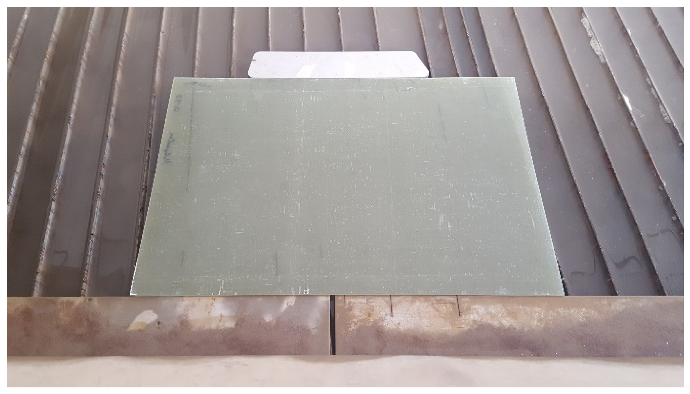
Figure 1.
Composite plate prepared for waterjet cutting.
Figure 1.
Composite plate prepared for waterjet cutting.
Figure 2.
Cut-out coupons.
Figure 2.
Cut-out coupons.
Figure 3.
Coupons mounted on special stainless-steel frame before submersion: (a) epoxy/glass; (b) polyester/glass.
Figure 3.
Coupons mounted on special stainless-steel frame before submersion: (a) epoxy/glass; (b) polyester/glass.
Figure 4.
Coupons: (a) with reinforcement tabs; (b) gripped in tensile testing machine.
Figure 4.
Coupons: (a) with reinforcement tabs; (b) gripped in tensile testing machine.
Figure 5.
Coupons after tensile testing; locations for microscopical examination.
Figure 5.
Coupons after tensile testing; locations for microscopical examination.
Figure 6.
Average mass gain due to seawater absorption: (a) epoxy resin; (b) polyester resin.
Figure 6.
Average mass gain due to seawater absorption: (a) epoxy resin; (b) polyester resin.
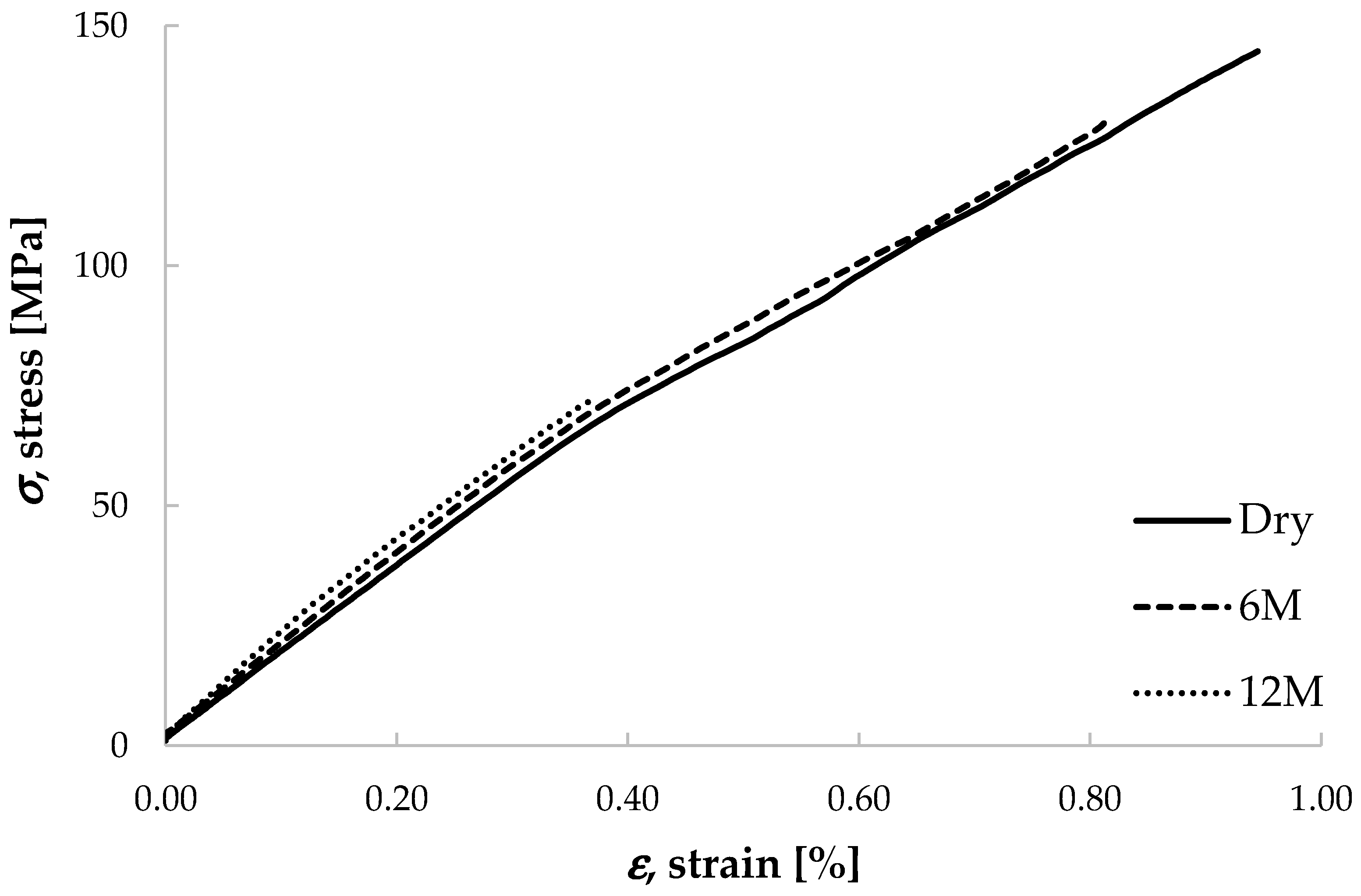
Figure 7.
Engineering stress-strain diagrams for epoxy/glass UD0° coupons submerged in sea for 6 (6 M) and 12 months (12 M).
Figure 7.
Engineering stress-strain diagrams for epoxy/glass UD0° coupons submerged in sea for 6 (6 M) and 12 months (12 M).
Figure 8.
Engineering stress-strain diagrams for epoxy/glass (0/90)s coupons submerged in the sea for 6 (6 M) and 12 months (12 M).
Figure 8.
Engineering stress-strain diagrams for epoxy/glass (0/90)s coupons submerged in the sea for 6 (6 M) and 12 months (12 M).
Figure 9.
Engineering stress-strain diagrams for epoxy/glass (0/45/90)s coupons submerged in sea for 6 (6 M) and 12 months (12 M).
Figure 9.
Engineering stress-strain diagrams for epoxy/glass (0/45/90)s coupons submerged in sea for 6 (6 M) and 12 months (12 M).
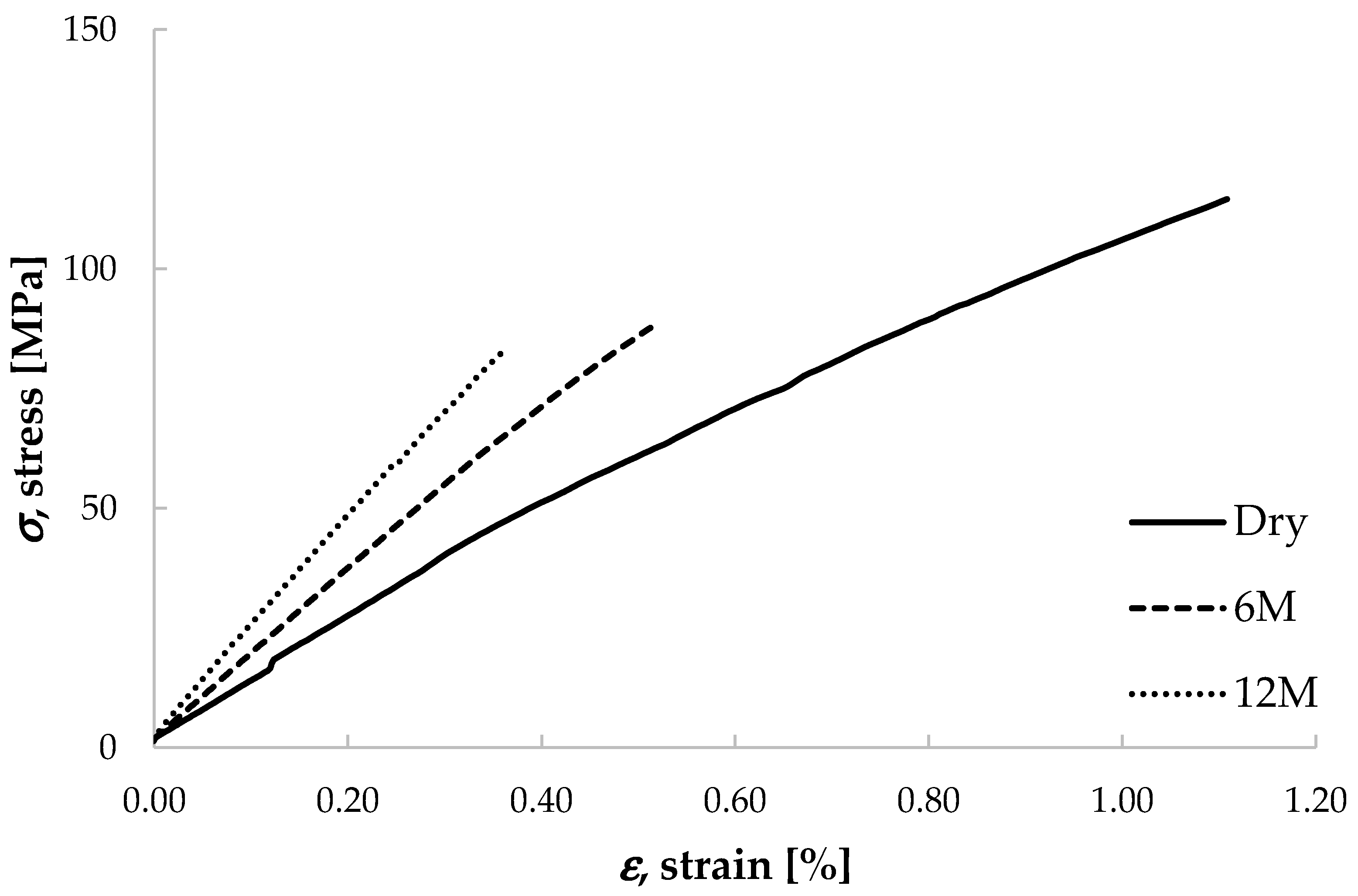
Figure 10.
Engineering stress-strain diagrams for polyester/glass UD0° coupons submerged in sea for 6 (6 M) and 12 months (12 M).
Figure 10.
Engineering stress-strain diagrams for polyester/glass UD0° coupons submerged in sea for 6 (6 M) and 12 months (12 M).
Figure 11.
Engineering stress-strain diagrams for polyester /glass (0/90)s coupons submerged in sea for 6 (6 M) and 12 months (12 M).
Figure 11.
Engineering stress-strain diagrams for polyester /glass (0/90)s coupons submerged in sea for 6 (6 M) and 12 months (12 M).
Figure 12.
Engineering stress-strain diagrams for polyester /glass (0/45/90)s coupons submerged in sea for 6 (6 M) and 12 months (12 M).
Figure 12.
Engineering stress-strain diagrams for polyester /glass (0/45/90)s coupons submerged in sea for 6 (6 M) and 12 months (12 M).
Figure 13.
Average tensile strength degradation: (a) epoxy resin coupons; (b) polyester resin coupons.
Figure 13.
Average tensile strength degradation: (a) epoxy resin coupons; (b) polyester resin coupons.
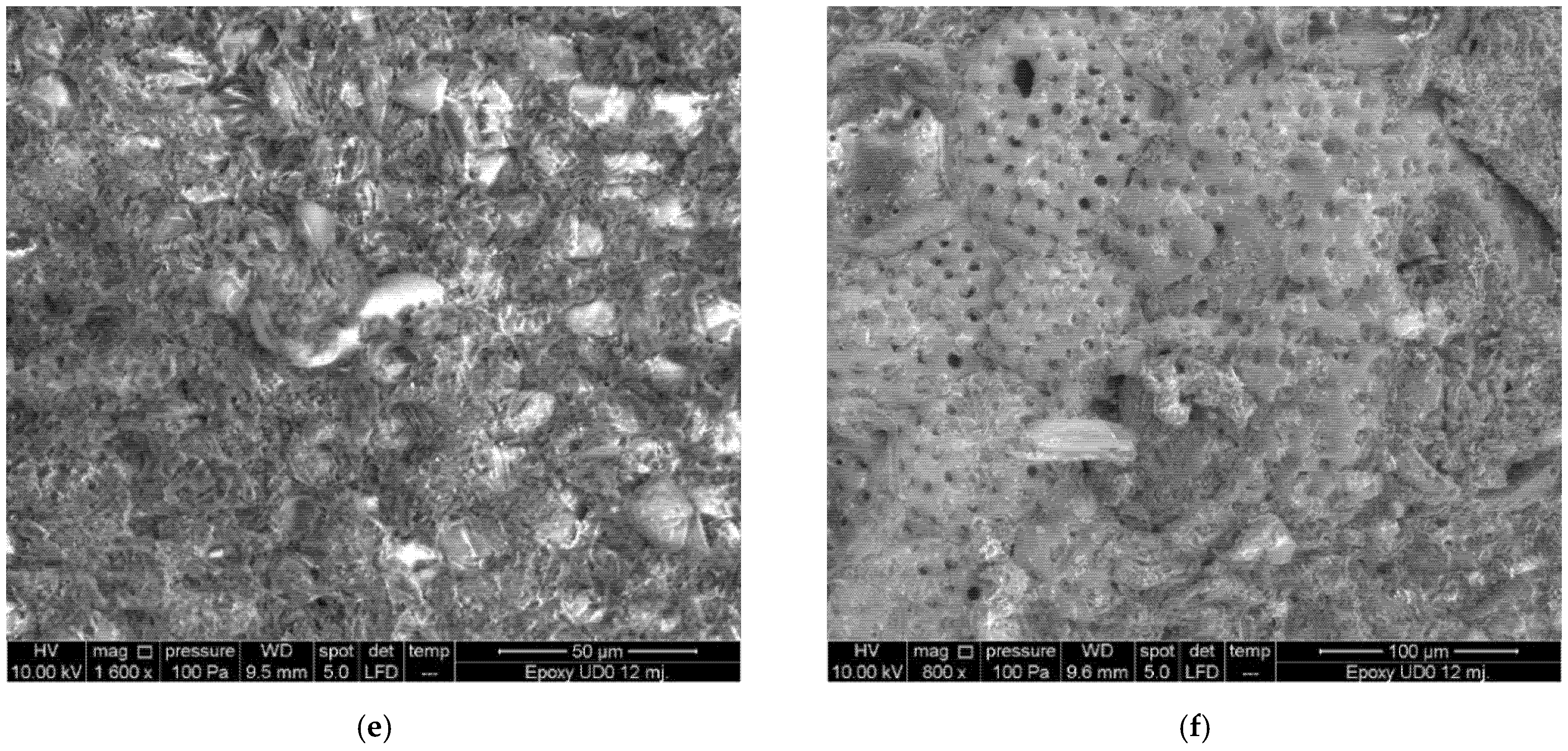
Figure 14.
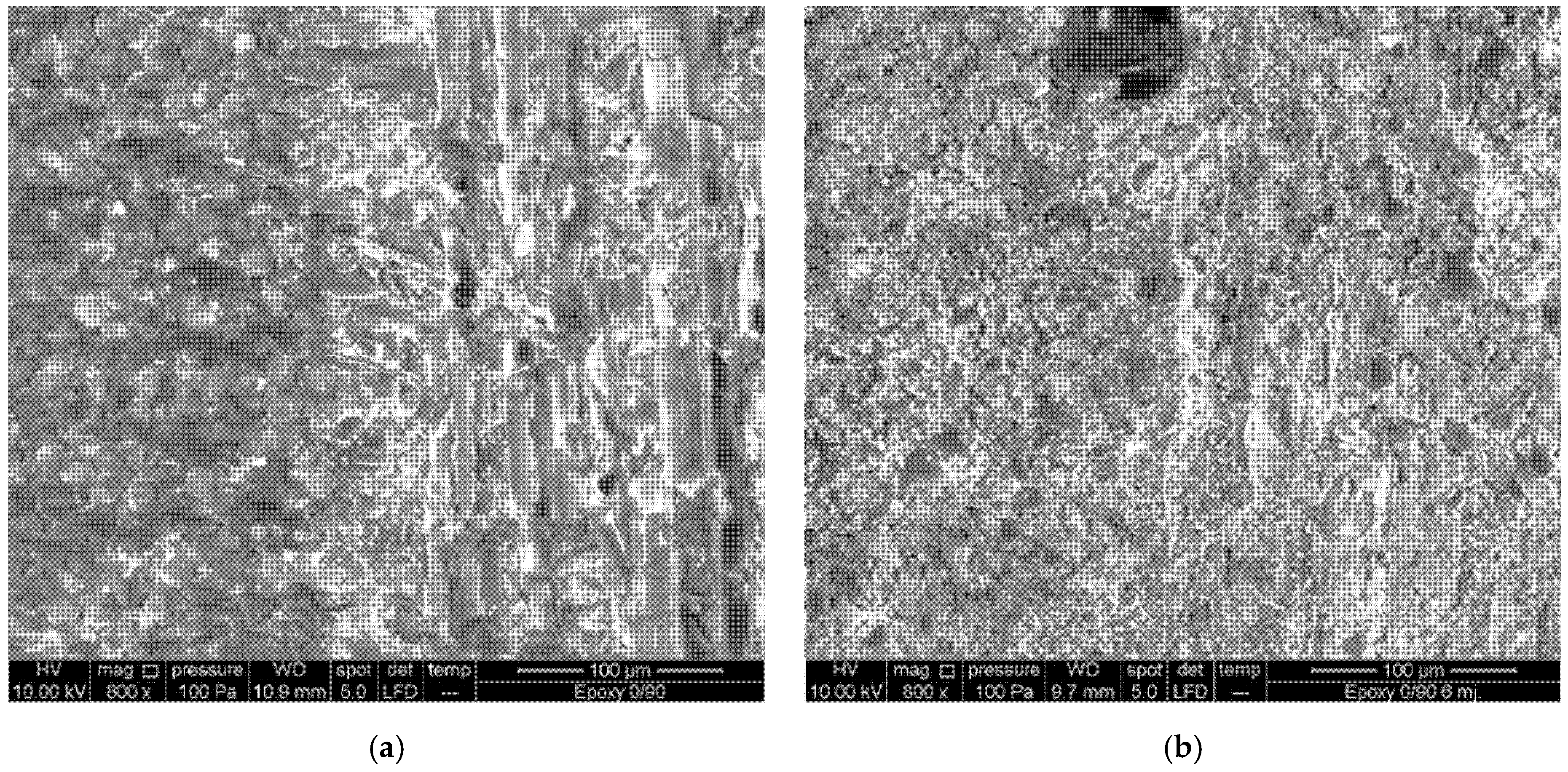
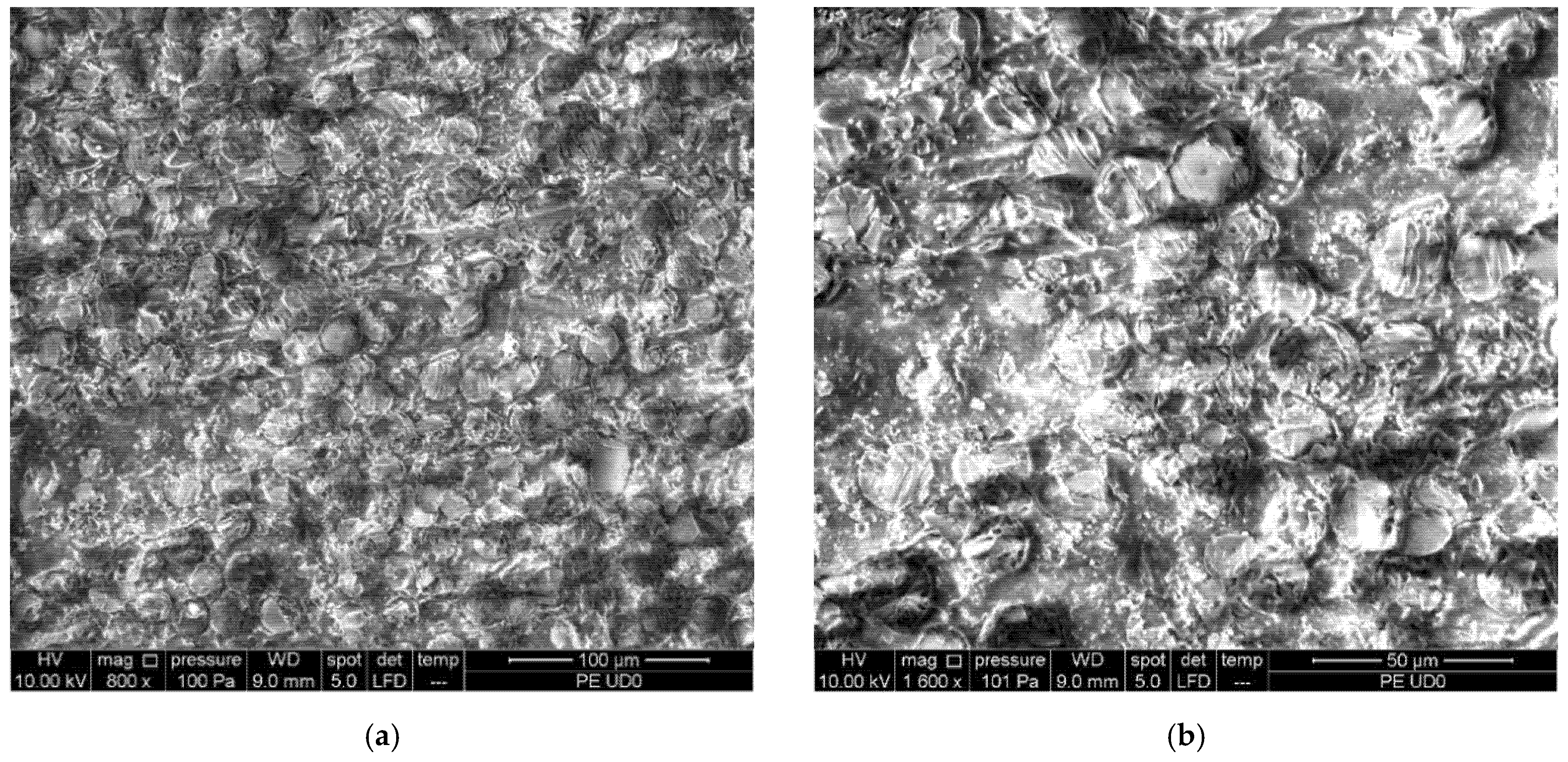
SEM epoxy UD0°: (a) dry; (b) 6 months submersion; (c,d) salt crystals after 6 months; (e,f) microorganisms’ growth after 12 months.
Figure 14.
SEM epoxy UD0°: (a) dry; (b) 6 months submersion; (c,d) salt crystals after 6 months; (e,f) microorganisms’ growth after 12 months.
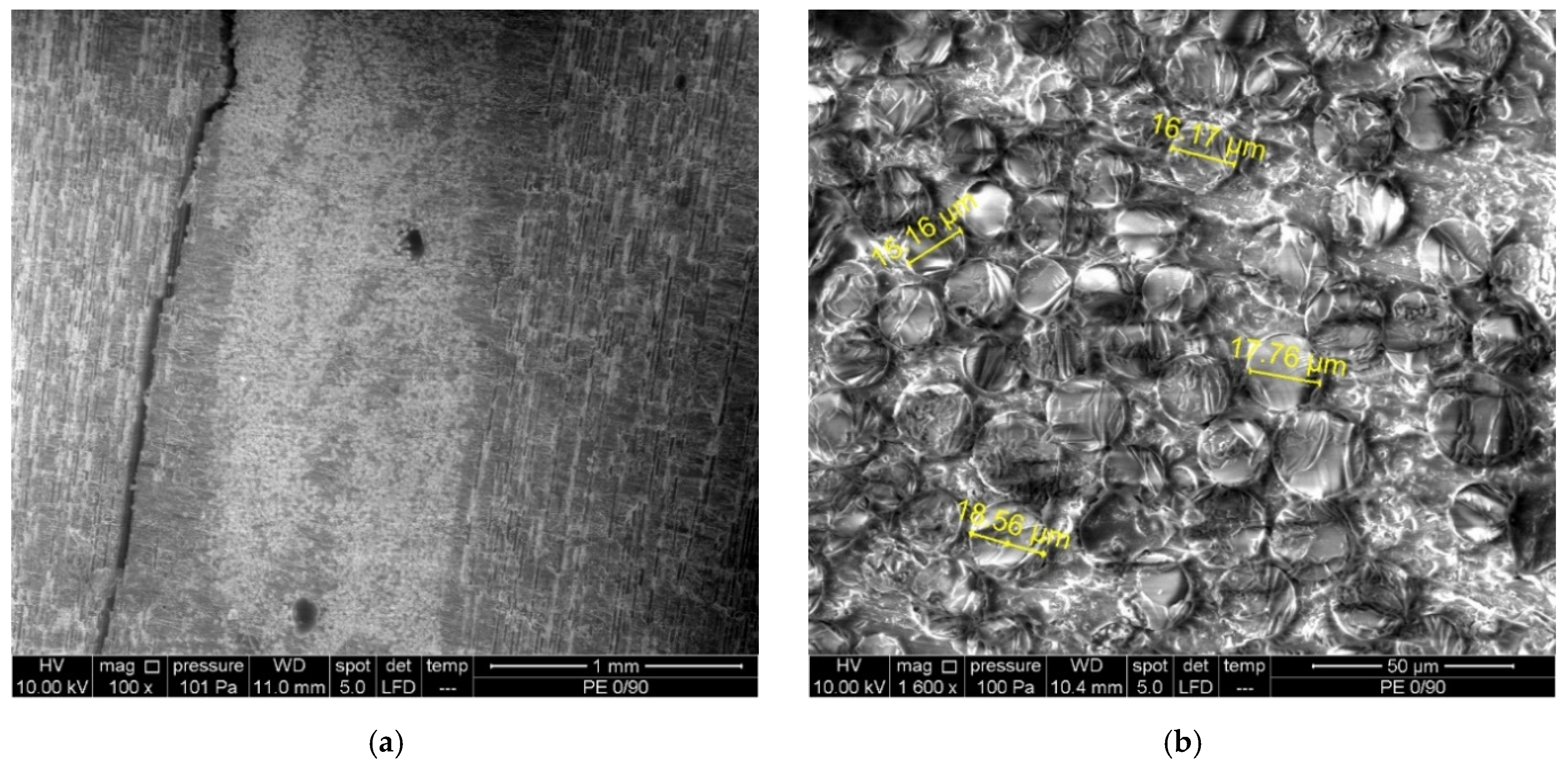
Figure 15.
SEM epoxy (0/90)s: (a) dry; (b) 6 months submersion; (c,d) salt crystal formations; (e,f) microorganisms’ growth after 12 months.
Figure 15.
SEM epoxy (0/90)s: (a) dry; (b) 6 months submersion; (c,d) salt crystal formations; (e,f) microorganisms’ growth after 12 months.
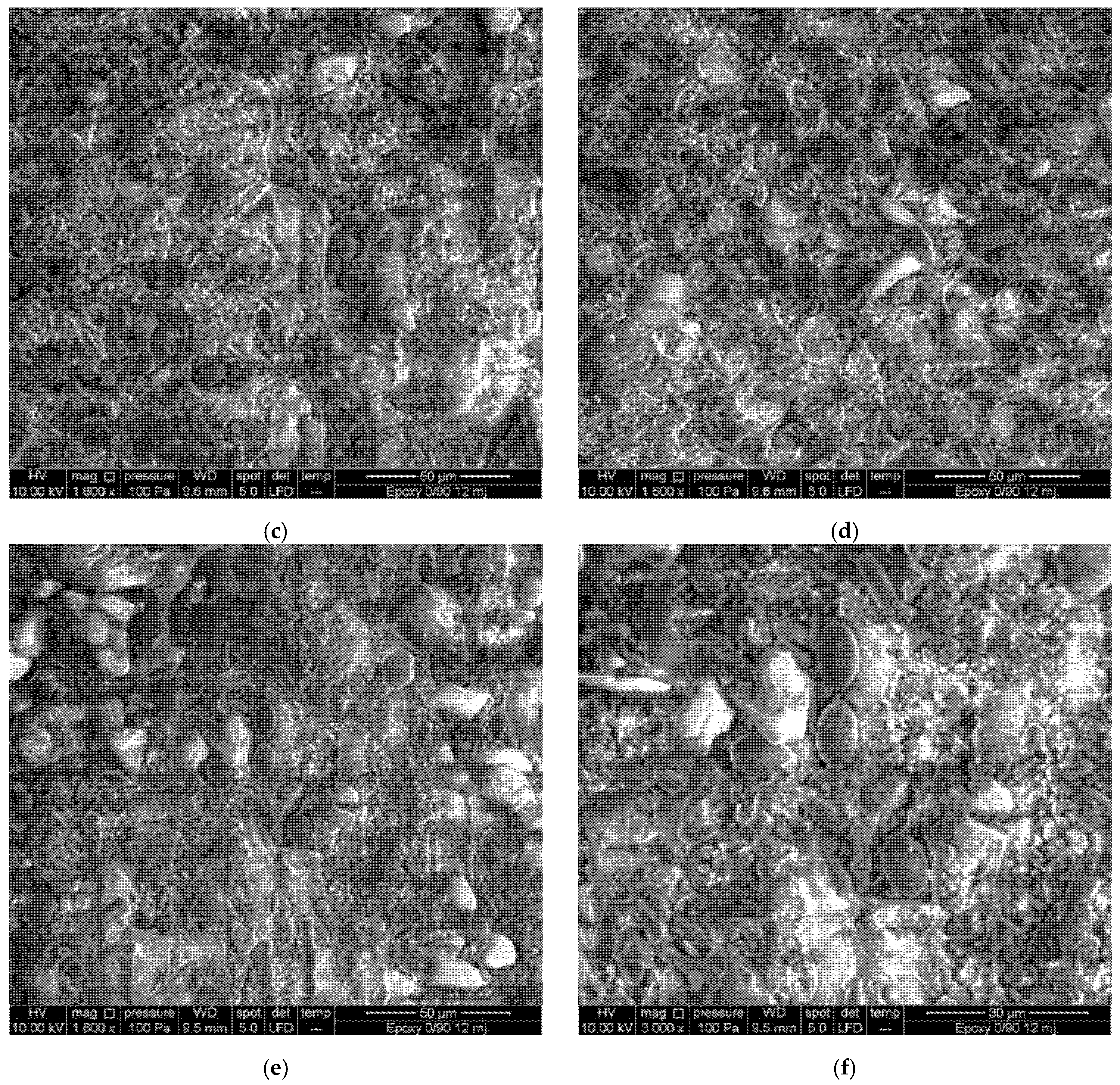
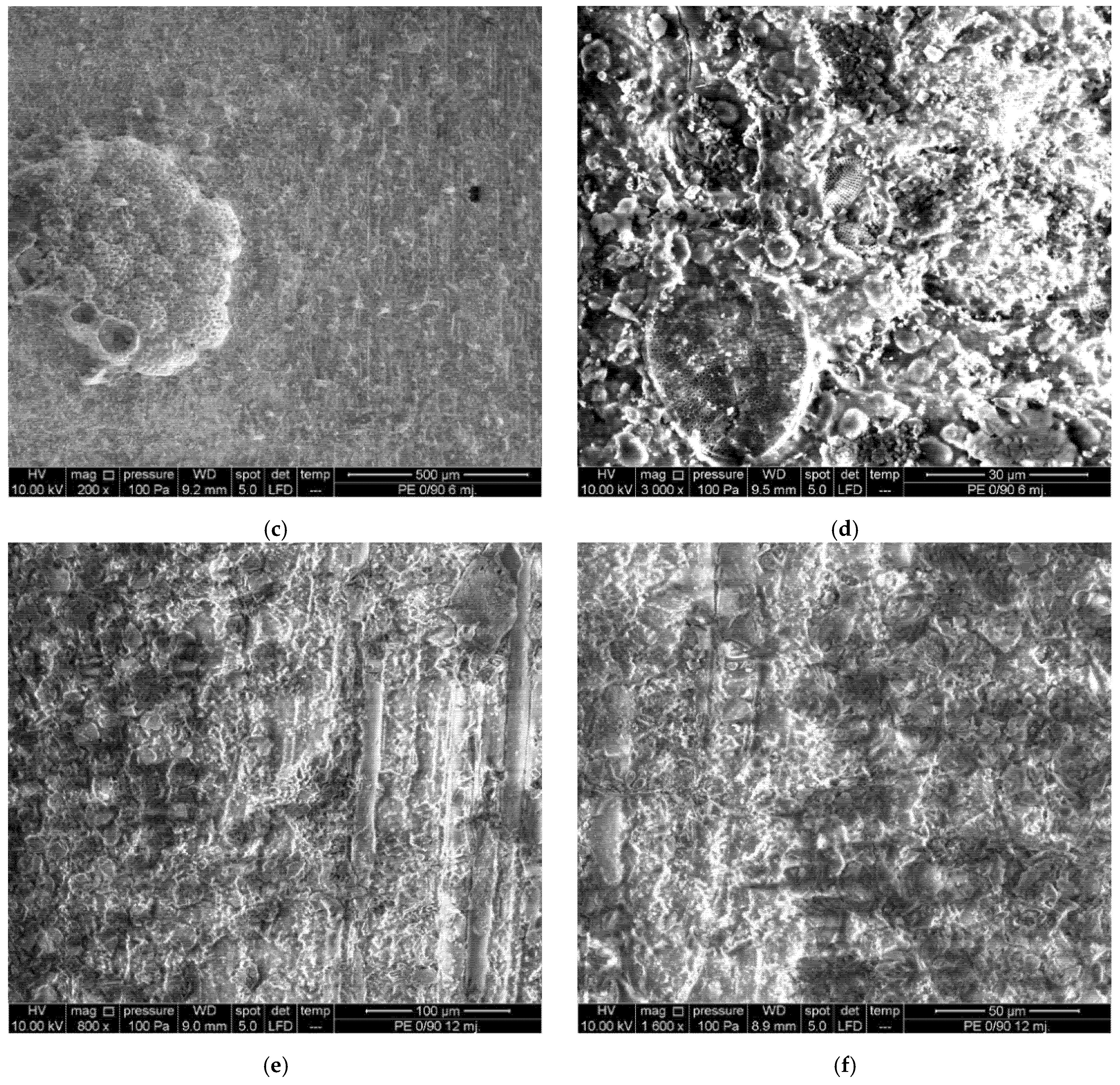
Figure 16.
SEM epoxy (0/45/90)s: (a) dry; (b–d) salt crystals 6 and 12 months submersion; (e,f) microorganisms’ growth after 6 and 12 months.
Figure 16.
SEM epoxy (0/45/90)s: (a) dry; (b–d) salt crystals 6 and 12 months submersion; (e,f) microorganisms’ growth after 6 and 12 months.
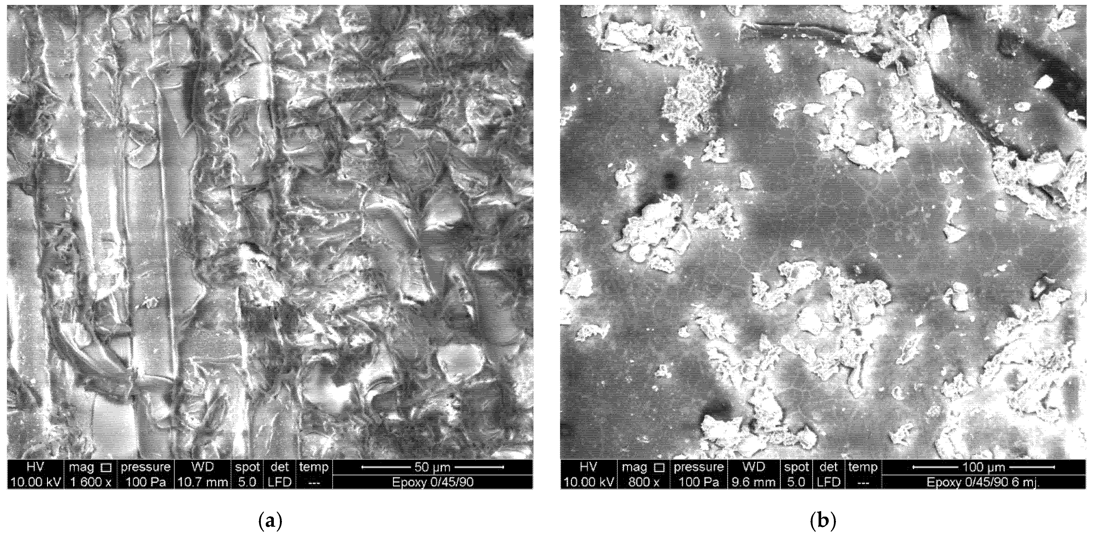
Figure 17.
SEM polyester UD0°: (a,b) dry; (c,d) salt crystals 6 months submersion; (e,f) 12 months submersion.
Figure 17.
SEM polyester UD0°: (a,b) dry; (c,d) salt crystals 6 months submersion; (e,f) 12 months submersion.
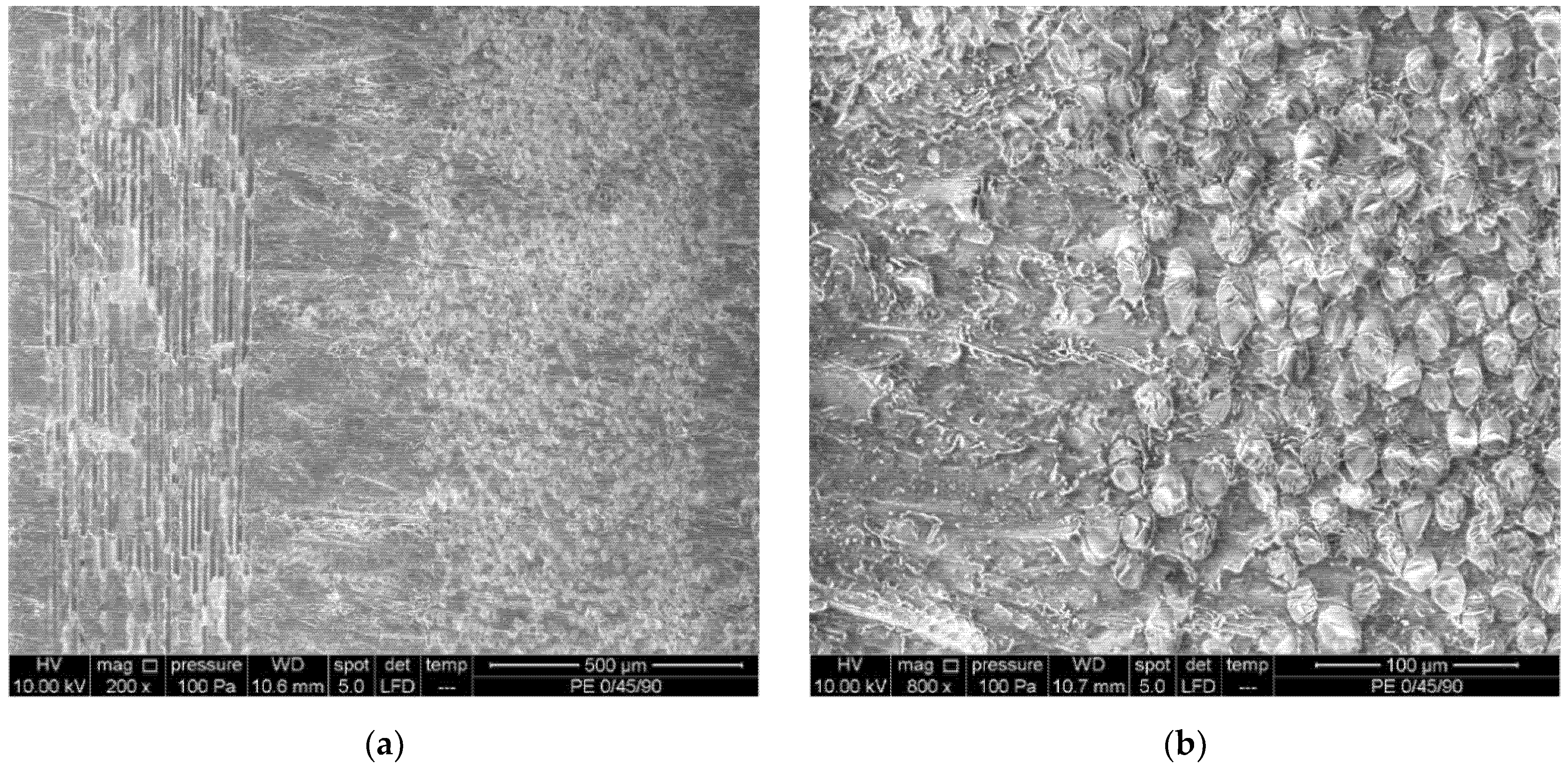
Figure 18.
SEM polyester (0/90)s: (a,b) dry, manufacturing imperfections; (c,d) microorganisms’ growth after 6 months of submersion; (e,f) 12 months of submersion.
Figure 18.
SEM polyester (0/90)s: (a,b) dry, manufacturing imperfections; (c,d) microorganisms’ growth after 6 months of submersion; (e,f) 12 months of submersion.
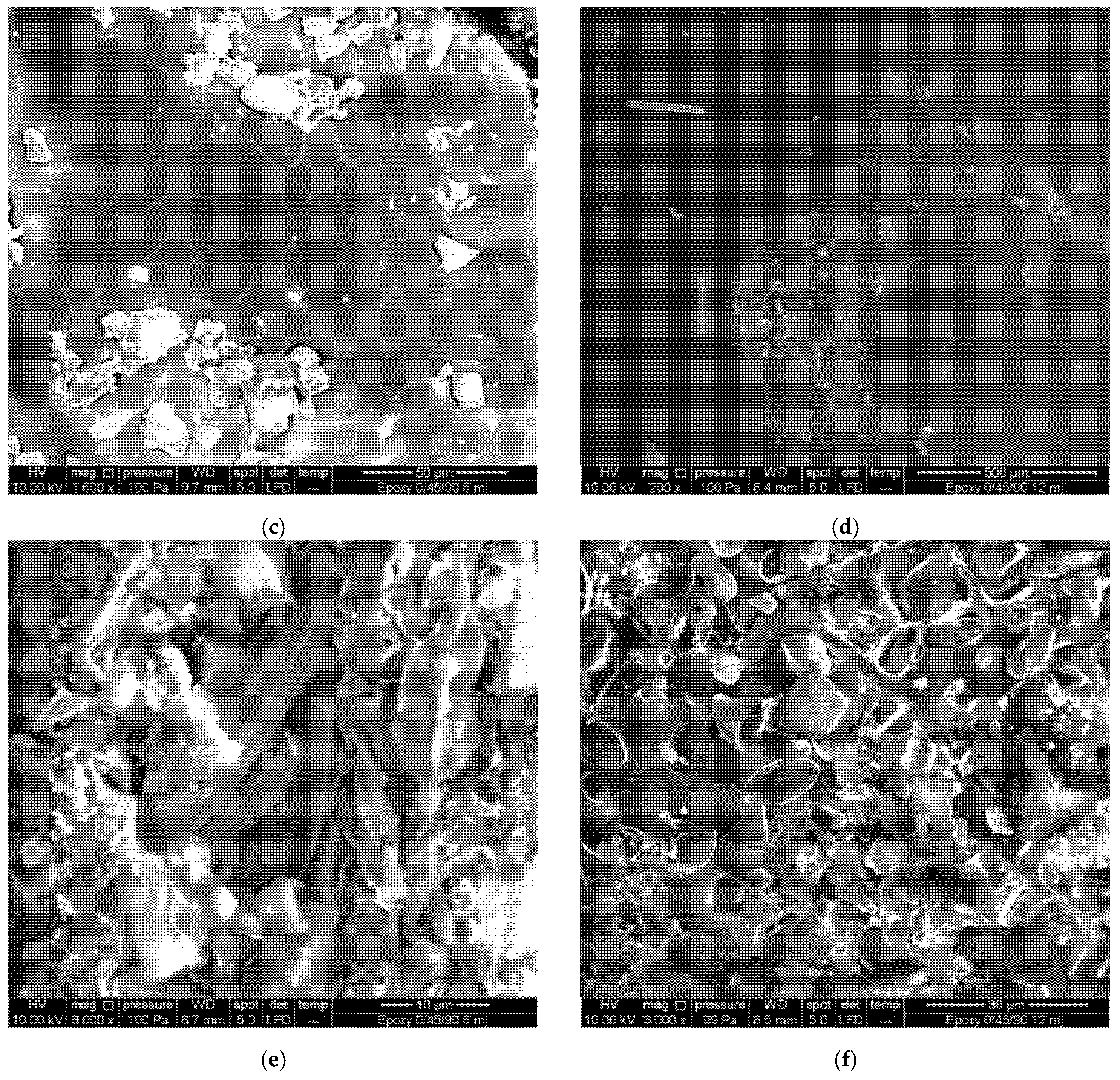
Figure 19.
SEM polyester (0/45/90)s: (a,b) dry; (c,d) resin degradation, 6 months submersion; (e,f) microorganisms in the resin, 12 months of submersion.
Figure 19.
SEM polyester (0/45/90)s: (a,b) dry; (c,d) resin degradation, 6 months submersion; (e,f) microorganisms in the resin, 12 months of submersion.
Table 1.
Resin systems properties.
Table 1.
Resin systems properties.
| Property | Epoxy | Polyester |
|---|
| Tensile strength [MPa] | 47 | 42 |
| Elasticity modulus [MPa] | 3240 | 2700 |
| Glass transition temperature [°C] | 50 | 55 |
Table 2.
Mass gain due to algae growth and water absorption.
Table 2.
Mass gain due to algae growth and water absorption.
| Resin | Period of Exposure | Mass Increase [%] |
|---|
| Minimum | Maximum | Average |
|---|
| Epoxy | 6 months | 0.929 | 3.892 | 1.971 |
| 12 months | 5.070 | 11.175 | 7.856 |
| Polyester | 6 months | 0.863 | 1.758 | 1.286 |
| 12 months | 2.551 | 13.940 | 8.687 |
Table 3.
Mass gain due to seawater absorption, epoxy resin.
Table 3.
Mass gain due to seawater absorption, epoxy resin.
| Fiber Layout Configuration | Period of Exposure | Mass Increase [%] |
|---|
| Minimum | Maximum | Average |
|---|
| UD0° | 6 months | 0.070 | 0.092 | 0.081 |
| 12 months | 0.133 | 0.300 | 0.217 |
| (0/90)s | 6 months | 0.158 | 0.211 | 0.175 |
| 12 months | 0.087 | 0.423 | 0.288 |
| (0/45/90)s | 6 months | 0.078 | 0.198 | 0.140 |
| 12 months | 0.252 | 0.502 | 0.381 |
Table 4.
Mass gain due to seawater absorption, polyester resin.
Table 4.
Mass gain due to seawater absorption, polyester resin.
| Fiber Layout Configuration | Period of Exposure | Mass Increase [%] |
|---|
| Minimum | Maximum | Average |
|---|
| UD0° | 6 months | 0.099 | 0.155 | 0.127 |
| 12 months | 0.018 | 0.199 | 0.103 |
| (0/90)s | 6 months | 0.194 | 0.258 | 0.222 |
| 12 months | 0.040 | 0.128 | 0.083 |
| (0/45/90)s | 6 months | 0.070 | 0.300 | 0.197 |
| 12 months | 0.173 | 0.266 | 0.213 |
| Publisher’s Note: MDPI stays neutral with regard to jurisdictional claims in published maps and institutional affiliations. |
© 2021 by the authors. Licensee MDPI, Basel, Switzerland. This article is an open access article distributed under the terms and conditions of the Creative Commons Attribution (CC BY) license (https://creativecommons.org/licenses/by/4.0/).


