Article

A Simplified Mechanistic-Empirical Flexible Pavement Design Method for Moderate to Hot Climate Regions

Highway and Airport Engineering Laboratory, Public Works Engineering Department, Faculty of Engineering, Mansoura University, 60 Elgomhoria St., Mansoura 35516, Egypt
*
Author to whom correspondence should be addressed.
Sustainability 2021, 13(19), 10760; https://doi.org/10.3390/su131910760
Submission received: 8 August 2021 / Revised: 24 September 2021 / Accepted: 24 September 2021 / Published: 28 September 2021

Abstract

:
Flexible pavement structure design is a complex task because of the variability of design input parameters and complex failure mechanisms. Therefore, the aim of this study is to develop and implement a simplified Mechanistic-Empirical (M-E) pavement design method based on the 1993 American Association of State Highway and Transportation Officials (AASHTO), the National Cooperative Highway Research Program (NCHRP) 9-22, and NCHRP 1-37A and 1-40D projects. This simplified methodology is implemented into a computer code and a user-friendly software called “ME-PAVE”. In this methodology, only two equivalent temperatures, as per the NCHRP 9-22 project, are estimated to adjust the dynamic modulus of the asphalt layer(s) for Asphalt Concrete (AC) rutting and AC fatigue cracking prediction instead of using the hourly climatic data, as in the AASHTOWare Pavement ME. In ME-PAVE, the structural responses at critical locations in the pavement structure are determined by a Finite Element Module (FEM), which is verified by a Multi-layer Elastic Analysis (MLEA) program. To ensure that the simplified methodology is practical and accurate, the incorporated transfer functions in the proposed simplified methodology are calibrated based on the Long-Term Pavement Performance (LTPP) data. Based on statistical analyses, the built-in FEM results exhibit very similar trends to those yielded by MLEA, with a coefficient of determination, R2 of 1.0. For all practical purposes, the proposed methodology, despite all simplifications, yields acceptable prediction accuracy with R2 of 0.317 for the rut depth compared to the current practices, NCHRP 1-37A and 1-40D (R2 = 0.399 and 0.577, respectively); while the prediction accuracy for fatigue cracking with R2 of 0.382 is comparable to the NCHRP 1-40D with R2 of 0.275. Nonetheless, the standard error for both distresses is in good agreement based on the investigated data and the developed methodology. Finally, the conducted sensitivity analysis demonstrate that the proposed methodology produces rational pavement performance.

1. Introduction

Roads are an essential part of any country infrastructure. Thus, researchers (i.e., [1,2,3,4,5,6,7,8,9,10,11,12,13,14]) have devoted great effort over recent decades to improve the structure design of flexible pavements. Figure 1 presents the evolution of pavement design methods (only the well-known methods) through the previous decades.
These methods can be classified into (a) methods based only on experience, which are typically used for designing local roads subjected to low traffic volumes, (b) empirical methods with/without a soil strength input [1], (c) limiting shear failure methods, (d) limiting deflection methods, (e) empirical methods based on pavement performance or road tests [5,7], and (f) Mechanistic-Empirical (M-E) methods [9,12,13]. However, the current state of pavement design practice is largely reliant on empirical methods, of which the most widely used one in the United States of America (US) and the Arab countries is the 1993 American Association of State Highway and Transportation Officials (AASHTO). Meanwhile, good sources of information can be found for traffic and material characteristics, climatic data, and field performance of pavement sections. This data formed the basis for the development and calibration of the first draft of the Mechanistic Empirical Pavement Design Guide (MEPDG) in April 2004, under two important research projects funded by the National Science Foundation (NSF); these projects are the National Cooperative Highway Research Program (NCHRP) 1-37A and NCHRP 1-40D [12,13].
Currently, the US Departments of Transportation (DOTs) implement different pavement structure design methods, and most DOTs implement more than one method of design for the same pavement type. A recent survey, in 2014, revealed that the AASHTO empirical methods (1993 and earlier versions) are by far the most used design methods among the US transportation agencies [15].
Although the AASHTO design guide (1993 and earlier versions) have proven its effectiveness in designing flexible pavements for years, the empirical nature limited the applicability of this method to certain conditions [12]. Specifically, (1) current traffic loading characteristics are very different than they were in the late 1950s, (2) only one cold climatic site, a fine subgrade soil, one Hot Mix Asphalt (HMA), and one rigid pavement mixture were used for the field test, (3) the road test did not include rehabilitated pavement sections, (4) drainage considerations were not taken into account and they are still very limited, (5) the monitoring time was very short (only two years after opening to traffic), (6) the layer coefficients have to be calibrated before implementing the design method, and finally, (7) the failure criteria is based on serviceability loss (subjective measure) rather than measurable pavement performance (objective measure).
On the other hand, the MEPDG procedure is intended for designing and analyzing new and rehabilitated pavement structures. Stresses, strains, and deflections at predefined critical locations are calculated either by a Multi-Layer Elastic Analysis (MLEA) or Finite Element Method (FEM), considering the materials/climatic properties and traffic characteristics. Empirical transfer functions use the critical responses with material properties to estimate pavement performance throughout the pavement design life. Pavement performance is expressed in the form of rutting (all layers), longitudinal and alligator fatigue cracking, thermal cracking, and pavement roughness. The prediction precision of the empirical models depends heavily on the hierarchical input levels of the design parameters and the calibration of the transfer functions [12,13].
In MEPDG (the latest production software version is the AASHTOWare Pavement ME Design, V2.5.5) [16]; the performance models for rutting and alligator fatigue cracking with the calibration coefficients are explained briefly in [13].
A recent survey demonstrated that 24 agencies had already implemented a M-E design method. The MEPDG represents one of these M-E methods, which is used or being evaluated by 13 agencies, while the other 11 agencies used other M-E design methods [15,17,18]. As reported, three agencies used the M-E approach to develop a design catalogue, while three agencies had already implemented MEPDG. Eight agencies expressed that there is no plan to implement the MEPDG at the current time. However, 43 agencies reported that they have plans for MEPDG implementation within five years [15,17,18].
Although, four states have already implemented MEPDG, more than 80% of the US have their own plans for implementing MEPDG [19]. To smoothly evolve from the present empirical design methods to the MEPDG, various DOTs conducted several research projects for the conversion [20,21,22,23,24,25,26]. The most important step to implement MEPDG successfully is to locally calibrate the performance models and build material and traffic characterization databases. Li et al. [27] listed most of the states that calibrated the performance models locally. The MEPDG local calibration effort is difficult in action because just 32 agencies provided the performance data for their highways, and only 17 agencies had material characterization database [19].
Many countries in Europe, Asia, and Africa have made efforts to prepare local design data, conducted sensitivity analyses, carried out the local calibration efforts, enhanced the pavement materials characteristics and modelling, and developed local calibration coefficients [24,28,29,30,31,32,33,34,35,36,37,38,39,40]. Most of these countries used some default design inputs (traffic characteristics and material properties) instead of local data, due to the scarcity of the required data. Also, in some cases, climate data was adopted from other locations with similar weather conditions. As well, different methodologies were followed in the local calibration efforts [24,32].
The major output of the NCHRP 9-22 was the development of the Quality-Related Specifications Software (QRSS) [41]. This software is a simplified method compared to the MEPDG. It was developed based on the MEPDG predictions from a large matrix of pre-solved pavement structures under different traffic and climatic conditions, using a range of material properties that cover the wide variety of practical cases a designer may face. Even though the QRSS software has been effectively used in many research studies, it should be noted that it only predicts distresses in the Asphalt Concrete (AC) layer(s) [42,43,44,45,46].
The QRSS predicts the AC rutting and alligator fatigue cracking as well as thermal cracks for a pavement structure and traffic level based on the HMA volumetrics, asphalt grade, climatic data, effective temperature (Teff), and AC effective dynamic modulus (E*eff). E*eff is a function of Teff, traffic speed, and pavement structure. Teff is a temperature at which an amount of AC rutting or fatigue cracking would be comparable to that from the temperature variations during the temperature cycles occurring throughout the pavement service life, as presented in Equations (1) and (2) for rutting and fatigue cracking, respectively [41]. Consequently, the effective asphalt modulus is a function of the effective frequency and temperature. The effective frequency for fatigue and rutting is a function of the effective depth, traffic speed, and modulus [41,47,48,49]:
T e f f r u t t i n g = 14.62 3.361 ln ( f r e q ) 10.94 ( z ) + 1.121 ( M A A T ) + 1.718 ( σ M A A T ) + 0.08 ( R a i n ) + 0.333 ( S u n s h i n e ) 0.431 ( W i n d )
T e f f f a t i g u e = 13.9551 2.3316 ( f ) 0.5 + 1.0056 ( M A A T ) + 0.8755 ( σ M M A T ) 1.1861 ( W i n d ) + 0.5489 ( S u n s h i n e ) + 0.0706 ( R a i n )
where
  • T e f f r u t t i n g = Modified Witczak effective temperature for rutting, °F,
  • T e f f f a t i g u e = Modified Witczak effective temperature for fatigue, °F,
  • z = Critical depth, in.,
  • f = Loading frequency, Hz,
  • MAAT = Mean annual air temperature, °F,
  • σ M M A T = Standard deviation of the mean monthly air temperature, °F,
  • Rain = Annual cumulative rainfall depth, inches,
  • Sunshine = Mean annual sunshine percentage, %, and
  • Wind = Mean annual wind speed (mph).
Furthermore, the concept of effective temperature and effective modulus was also used in other studies to propose rational AC structural layer coefficients (a1) for the AASHTO 1993 design method [17,18].
Even though the MEPDG method represents a paradigm shift in the pavement design, it has some drawbacks, as follows:
  • AASHTOWare pavement M-E software is expensive (i.e., 7000 US dollars per year for an individual workstation). It is even more expensive for international licensing to interested parties located outside the US and Canada, and whose organizations are not AASHTO members.
  • It is data intensive and sometimes not readily available, such as the axle load spectra and climatic data.
  • Some of the required data, even though are very comprehensive and difficult to obtain, may not be used in the analysis process. For example, the MEDPG does not link the hourly climatic data to the hourly traffic distribution factors for flexible pavement analysis/design [30,50].
  • The latest AASHTOWare Pavement ME kept only the MLEA module to estimate the structural responses at critical locations. The FEM was taken out from the latest version of the software.
Therefore, the main objective of this study is to develop an accurate but simplified M-E flexible pavement design and analysis method based on the outcomes of the NCHRP projects (1-37A, 1-40D, and 9-22); besides, accomplishing the following tasks:
  • Check the accuracy of the developed simplified M-E design system for flexible pavements, which suits moderate to hot climate regions.
  • Calibrate the performance models based on the Long-Term Pavement Performance (LTPP) data.
  • Conduct a sensitivity analysis of the performance models based on the main inputs.
  • Develop a user-friendly software for the structure design and analysis of flexible pavements in moderate to hot climate regions.
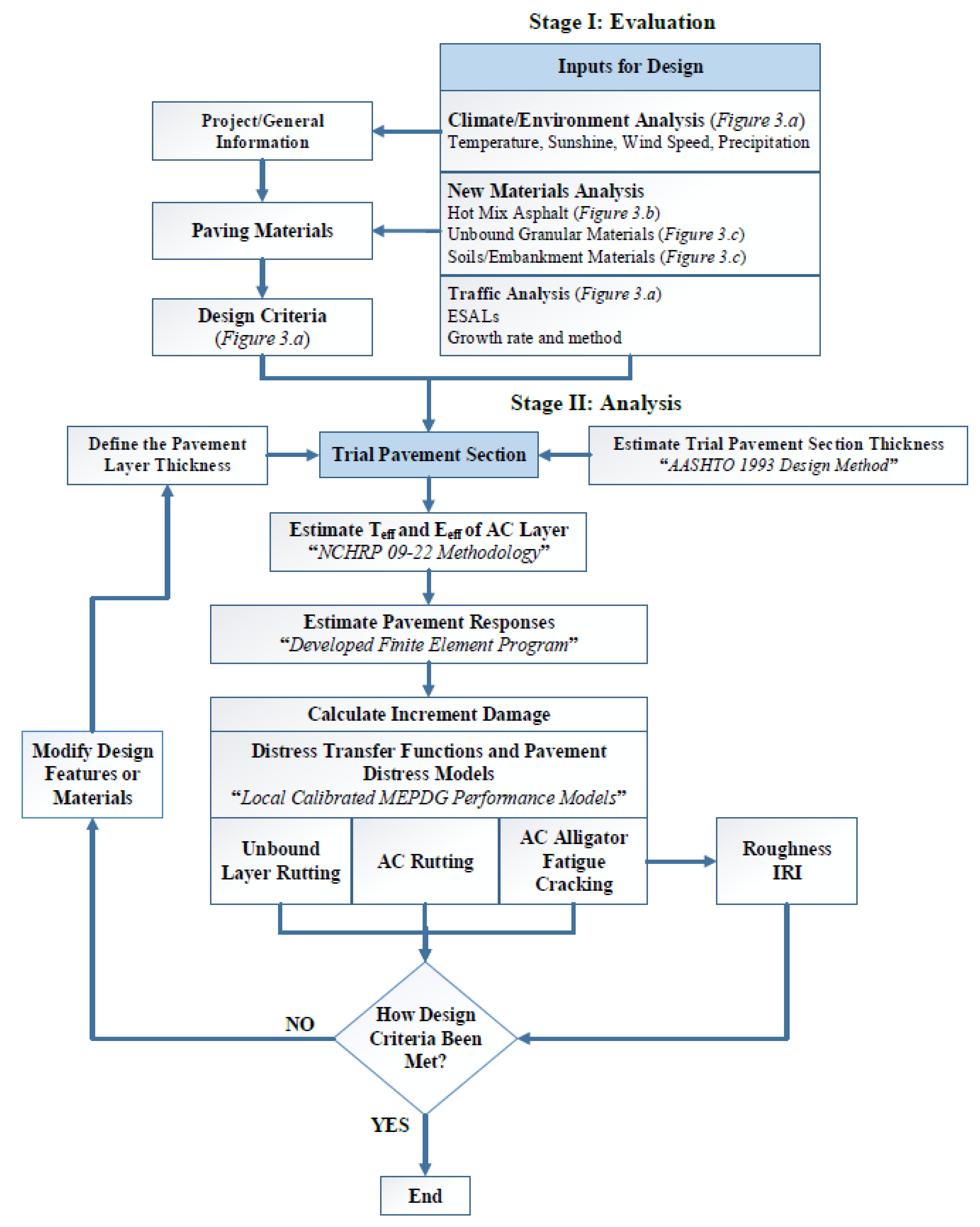
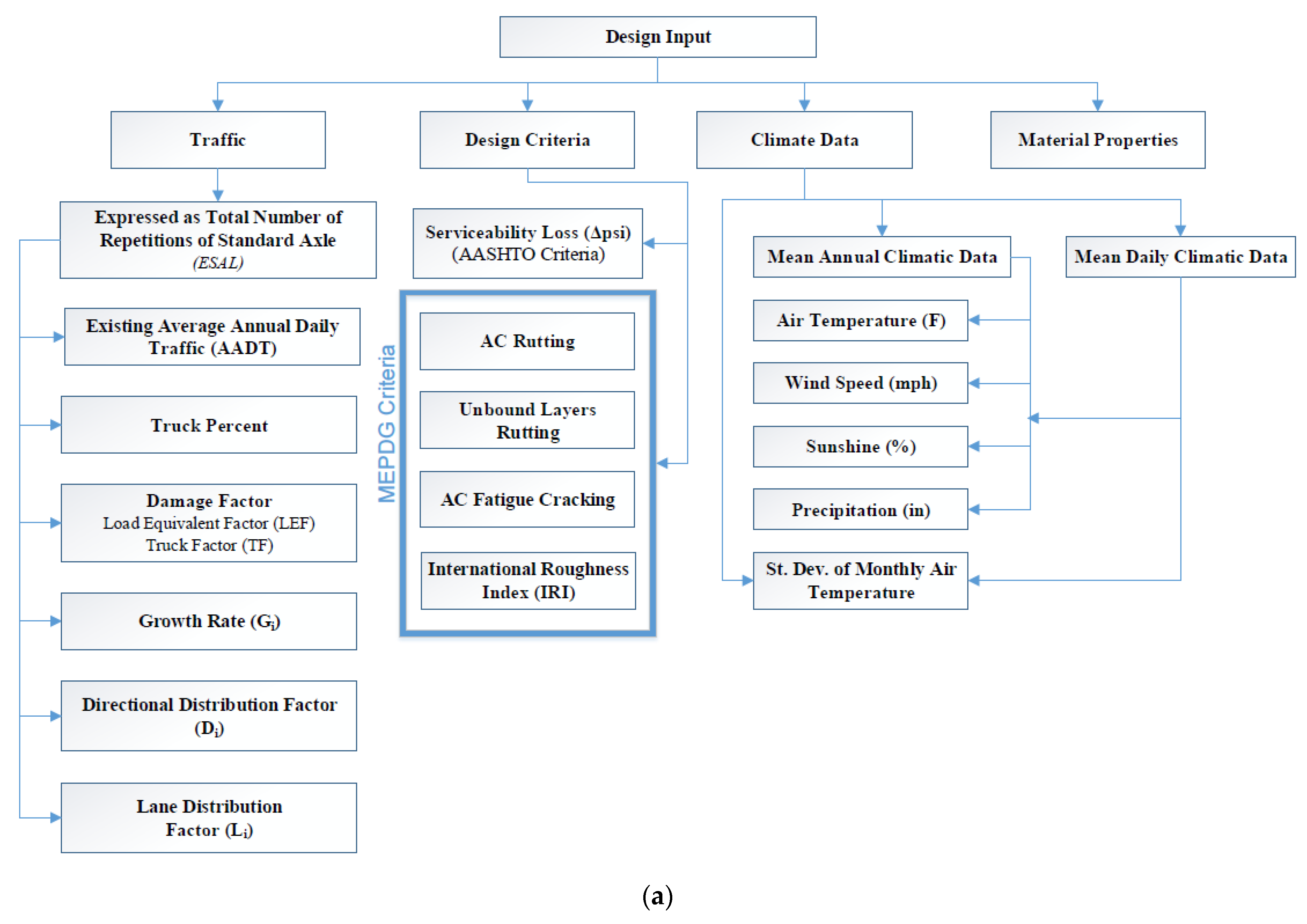
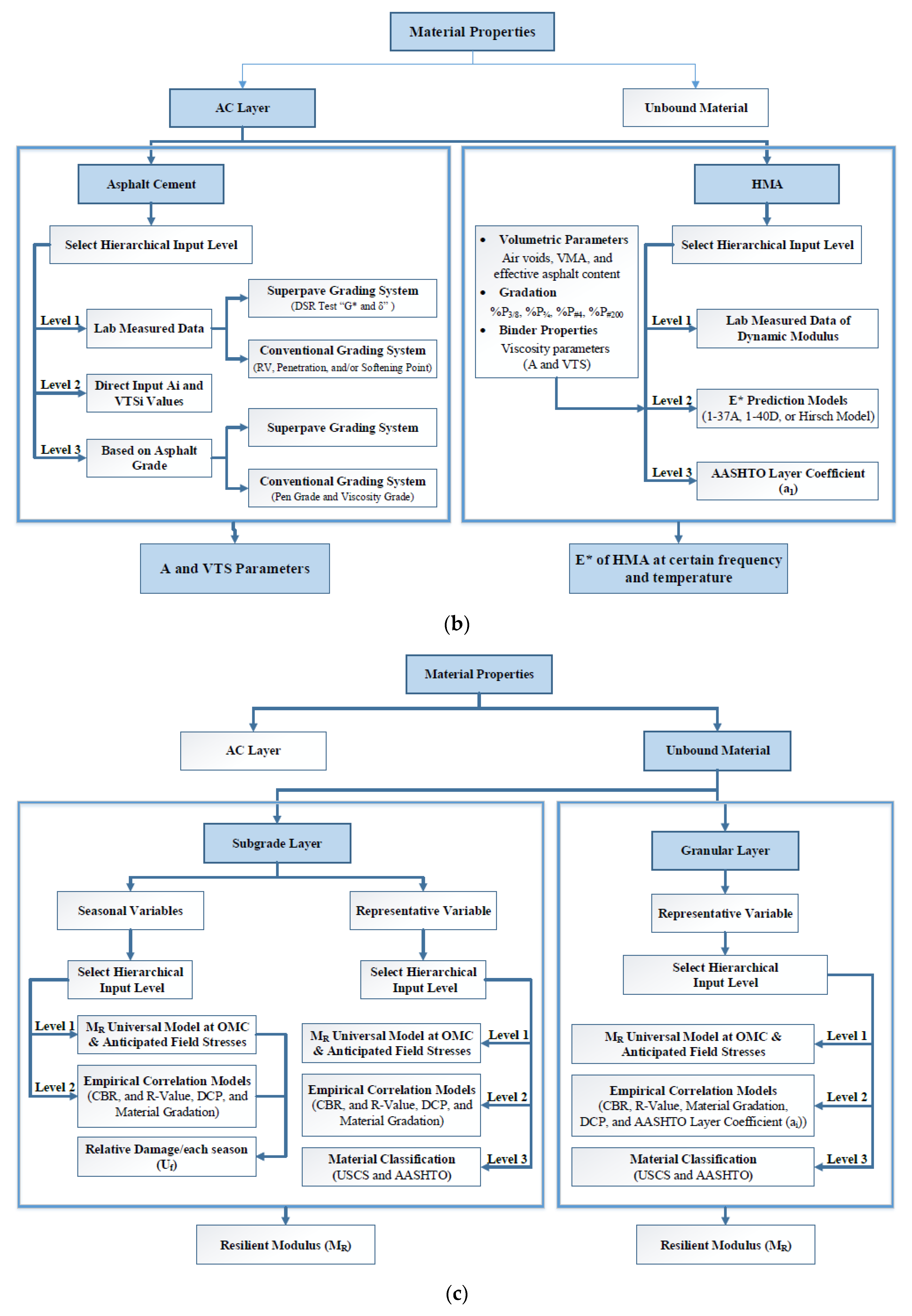
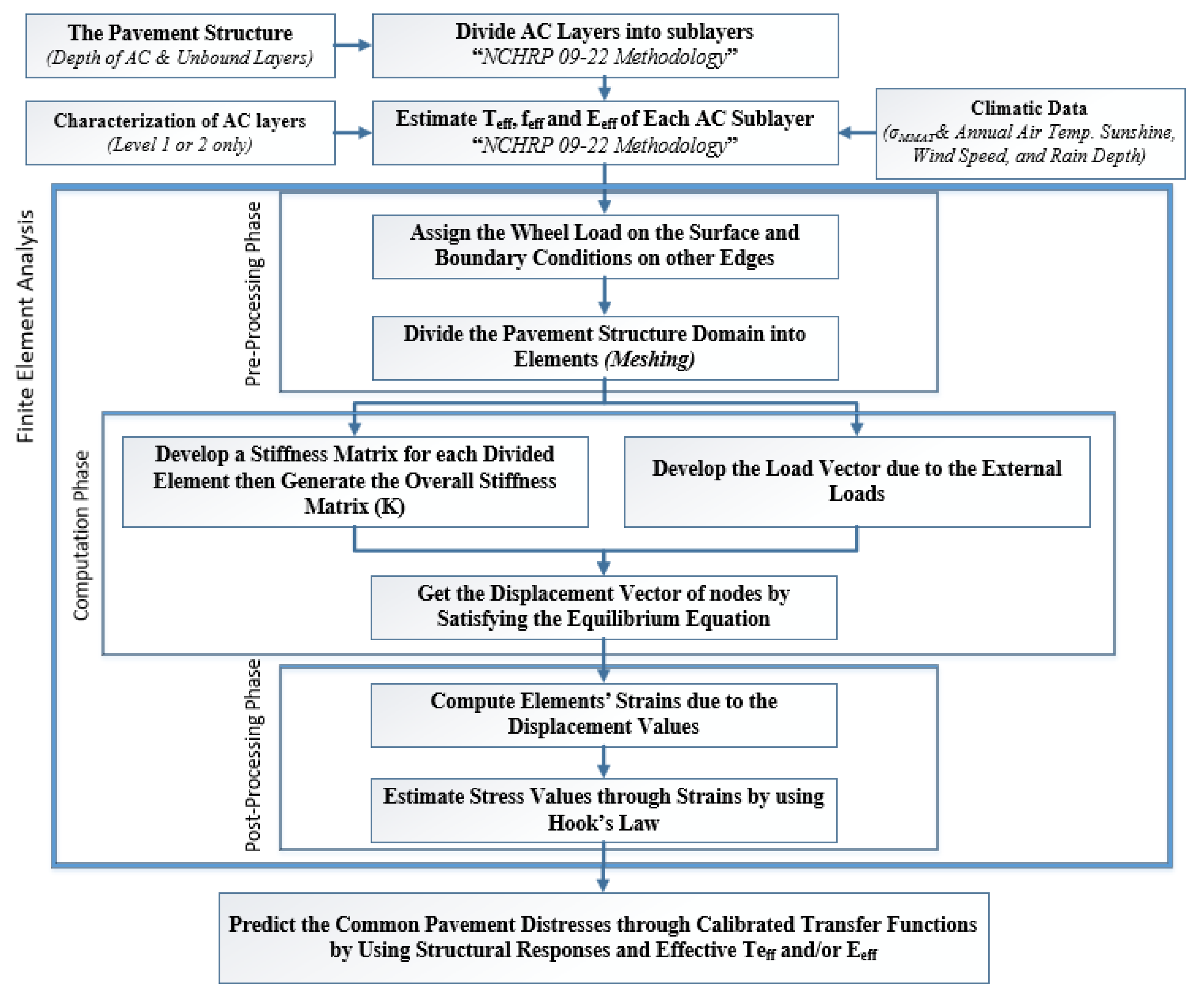
Due to the limited funds available for constructing new roads, especially lately, due to the COVID-19 pandemic, a simple design/analysis tool that links the material properties comprehensively with the structure of the pavement system is required. Such a tool will provide sustainable pavement structures. Besides, significant savings in pavement construction cost along with better performing pavements are expected. Moreover, a pavement management system can be proposed in the design stage, since the performance of the design section over the service life will be predicted.

2. Methodology

In this research, a simplified M-E design approach was developed based on the principles of the NCHRP 1-37A, NCHRP 1-40D, and NCHRP 9-22 projects. Figure 2 and Figure 3 present flow charts of the analysis/design steps followed by the proposed methodology.
In the proposed methodology, the AASHTO 1993 design method is still used to design an initial pavement structure based on the user inputs (i.e., material properties “modulus”, traffic data in terms of the classical and well-known 18-kips Equivalent Single Axle Load (ESAL)”, design reliability, and design criteria). Alternatively, the user has the option to directly input a trial pavement structure based on the designer experience for further analysis. Then, the predicted effective temperature for each distress, based on the climatic data and AC properties, is used to adjust the AC dynamic modulus, which has a considerable effect on the anticipated AC rutting and alligator fatigue cracking distresses (Equations (1) and (2)). After this, a simple FEM module is used to compute the structural responses (e.g., stresses, strains, and deflections) at predefined critical locations within the pavement system. Finally, these responses are converted into distresses (rutting, AC fatigue cracking, and roughness) through the calibrated performance models (the same models used in MEPDG; refer to AASHTO 2008) for each distress type [13].
The developed methodology was compiled into a user-friendly computer code (ME-PAVE) and was validated through numerous comparisons with most recently used software (e.g., AASHTO 1993 design tool, QRSS, and KENLAYER).

2.1. Effective Temperature and Modulus

To simplify the proposed methodology and the required climatic input data, the effective temperature and dynamic modulus concepts, which have been used in the QRSS, are also used. The software conducts a series of iterations to predict the effective temperature and modulus at critical depths for the AC rutting distress, taking into consideration the influence of climatic factors, traffic, and AC parameters similar to the QRSS methodology [41,47,48,49]. The calculation details of the effective temperature can be found in [47,48,49,50,51].

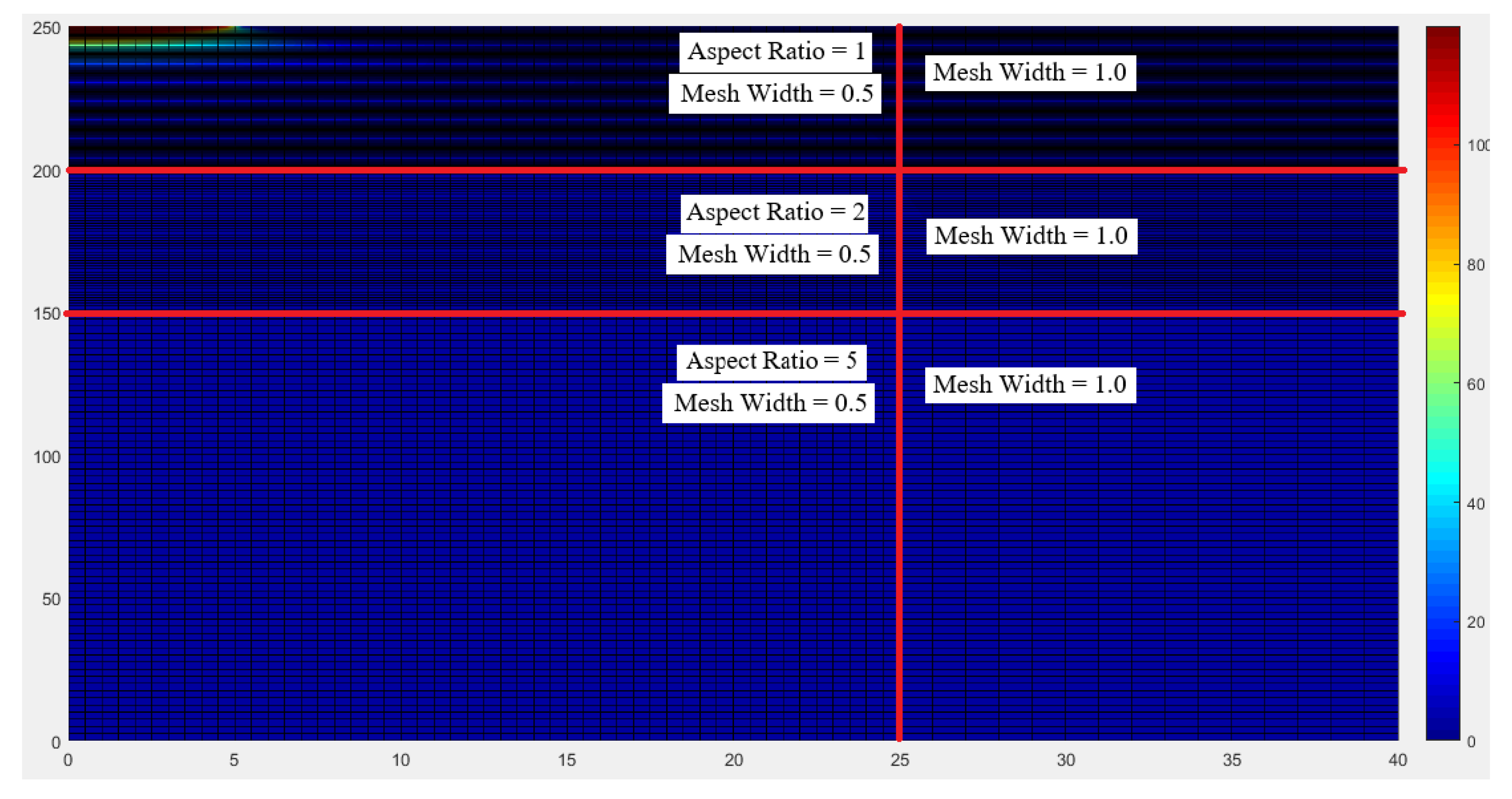
2.2. Finite Element Module

For simplicity and saving the run time of the software without compromising the accuracy, a linear elastic FEM was developed using a typical axisymmetric model with a quadratic quadrilateral element. The FEM was firstly coded by MATLAB, and after that was converted to C-Sharp (C#) and implemented in the developed ME-PAVE software to calculate the structural responses, at critical locations within the pavement structure. In addition, the tire pressure was assumed to be uniformly distributed on the pavement surface. Thus, the flexible plate was selected to represent traffic loading and the contact area of the tire imprint was assumed as a circular area.
A large matrix of computer simulation runs was completed to determine the optimum location of the boundary conditions. It was observed that the best location for the vertical boundary condition should not be closer than 12 times the contact radius, while the horizontal boundary condition should not be closer than 30 times the contact radius (total depth = 150 in (381 cm)) as displayed in Figure 4. These results agree with the recommended ones documented by [52,53]. Moreover, the element size was evaluated to select the optimum mesh size. A uniform layer was used to investigate the optimum mesh size. For creating the mesh at critical locations (i.e., under the wheel load), a fine mesh size (mesh width = 0.5-in (1.27 cm)) with unity aspect ratio was employed, as displayed in Figure 5.
In order to reduce the computational time without losing accuracy, different element sizes with higher order polynomial interpolations and different aspect ratios were implemented in the developed FEM program. Figure 6 demonstrates the flow chart of developing the pavement structure domain and the FEM process to compute the structural responses at critical locations, which are used to predict the common pavement distresses through the calibrated transfer functions.

3. Results and Discussion

The following subsections describe the results and discussion of the FEM verification, calibration of distress models based on the simplified methodology, and sensitivity analysis.

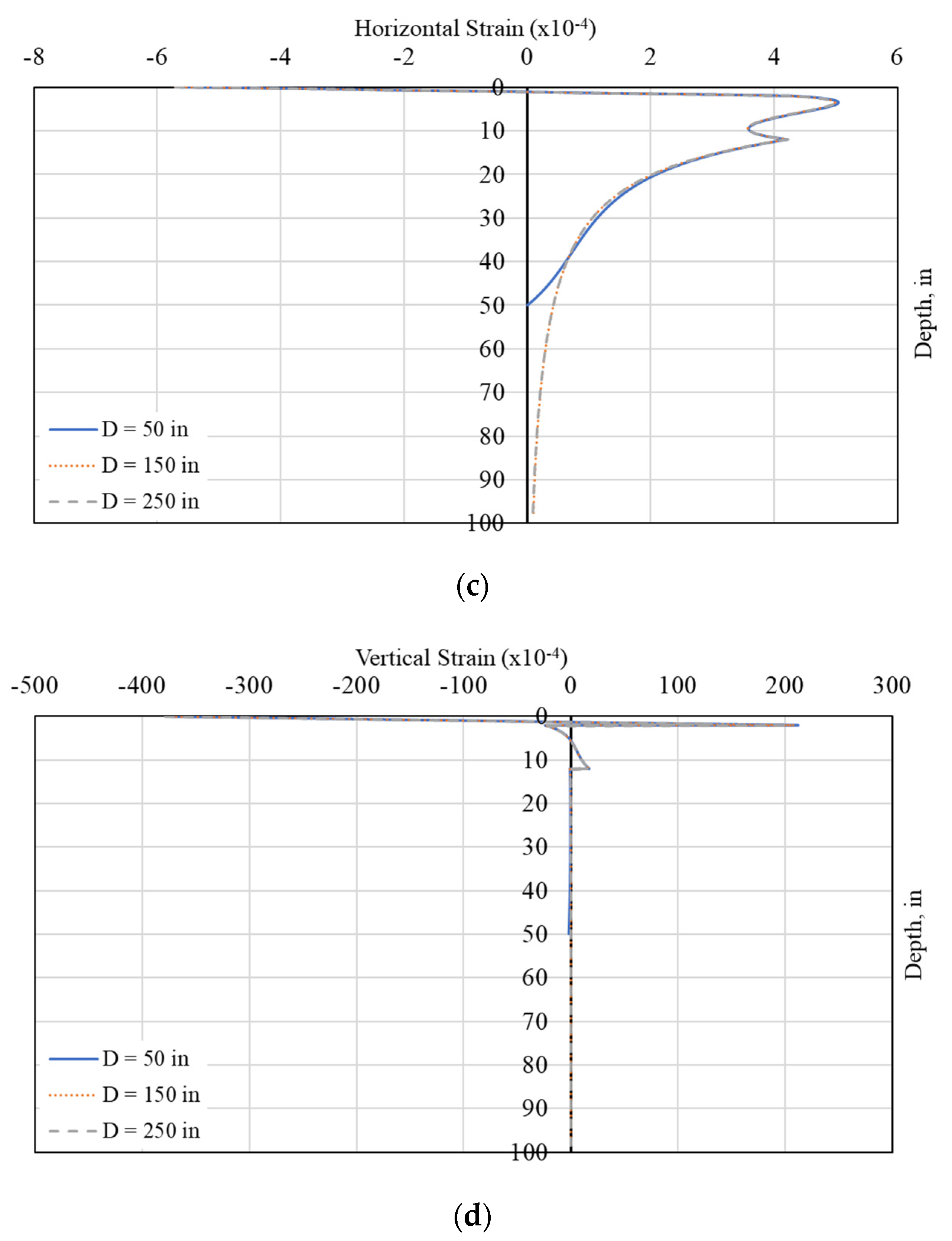
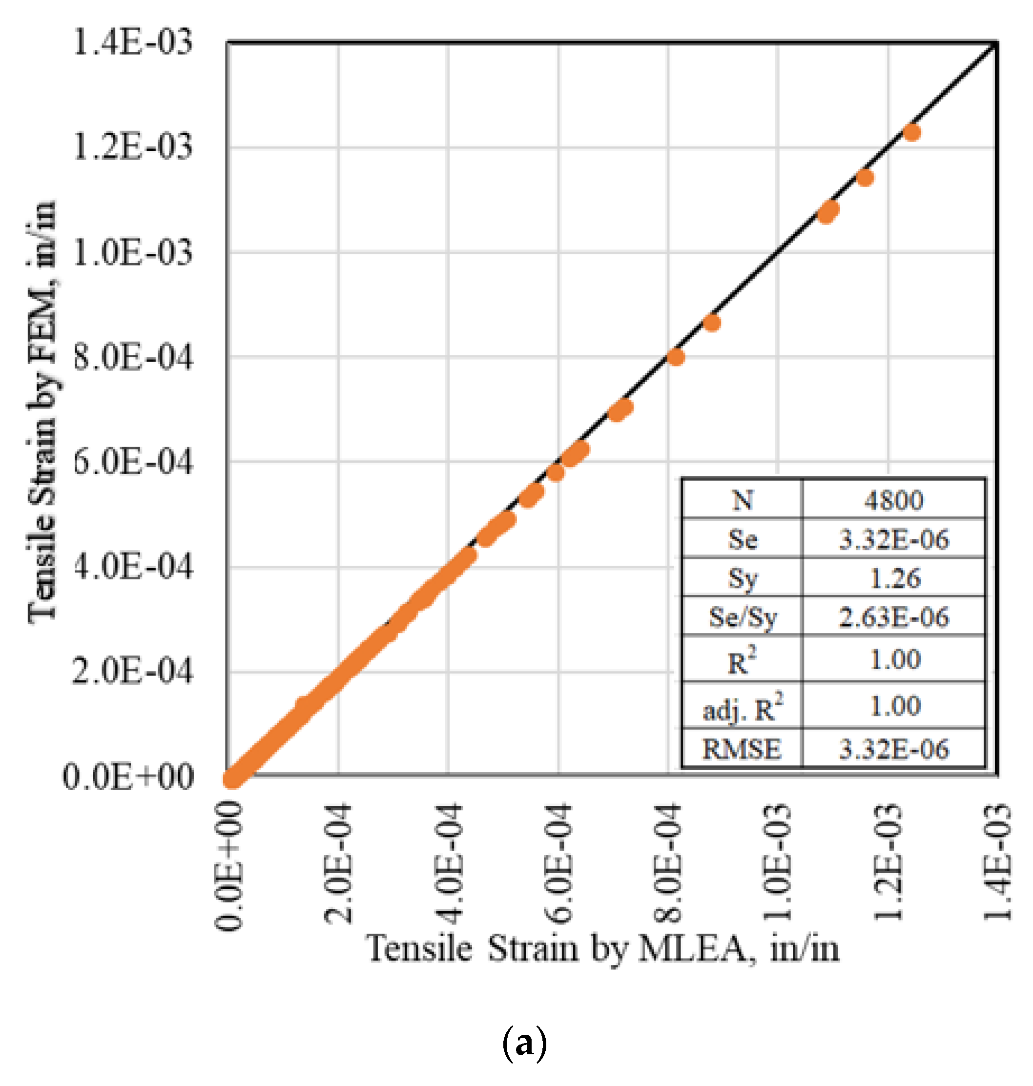
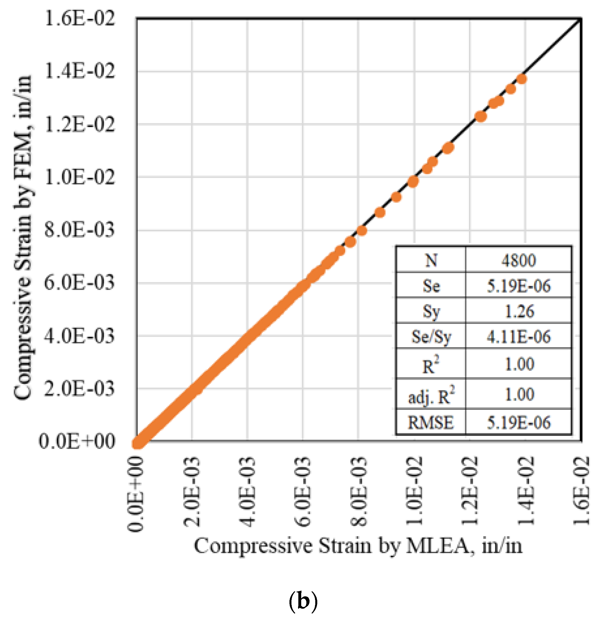
3.1. Verification of the Finite Element Module

It is important to verify the computed structural responses and the linearity by the developed FEM approach. A two-layer flexible pavement structure was selected with different material properties, as presented in Table 1, and different wheel loadings. The selected pavement sections were divided into sublayers and the structure responses were computed using the developed FEM program in comparison with a MLEA module (KENLAYER program). A total of 384 simulations for both modules were performed to obtain the horizontal tensile and vertical compressive strains at different points in the pavement layers.
The estimated response parameters were used for the alligator fatigue cracking and rutting predictions in the respective layers. It is important that the responses from the two approaches result in almost similar values. Figure 7a,b display a comparison between the developed FEM and MLEA for the tensile and compressive strains, respectively, along with the equality line and the statistical goodness of fit parameters for the two-layered system. The goodness of fit statistics included the coefficient of determination (R2), adjusted R2 (adj. R2), the ratio of the standard error of estimate to standard deviation of the measured values (Se/Sy), and the Root Mean Square Error (RMSE). As the figures imply, for all practical purposes, both modules yielded very similar results. This indicates that the developed FEM is a reliable tool for the computation of the distresses and performance evaluation, as presented further in this paper.
Moreover, one of the basic assumptions of the linear analysis is that the structural responses (stress and/or strain) are linearly proportional with the applied load. Thus, a typical three-layer structure (EAC = 400 ksi (2757.90 MPa), dAC = 4 in. (10.2 cm), Ebase = 35 ksi (241.3 MPa), dBase = 10 in. (25.4 cm), and Esubgrade = 7.5 ksi (51.7 MPa)) was selected to check the linearity of the developed model. Results display linear relationships between the applied traffic load and the computed pavement response at a given location, as displayed in Figure 8.

3.2. Calibration of the Distress Models

The performance models are recommended to be calibrated based on local materials, climate, traffic, and actual field performance, to ensure accurate design. The required steps, which was followed to calibrate these models, are provided in [54].
The hierarchical input levels of the design input parameters are considered the main factors, which affect the precision of the transfer functions calibration and consequently the accuracy of predictions. Thus, the performance models were calibrated based on LTPP data. For the developed methodology, only wet and dry non-freeze climate regions were selected.
Firstly, all the data points were selected from the General Pavement Studies (GPS) sections, with no AC overlays or any crack sealing maintenance. The selected sections were 36 sections including 176 data points for the rutting models and 29 sections with 115 data points for the AC fatigue cracking model. This complies with the sample size required for calibration, as noted in AASHTO 2010 [54].
Secondly, before starting the calibration process, the collected data points were firstly matched and all the missing data, such as material properties, were carefully assumed, based on previous studies (i.e., MEPDG), experience, and/or statistical analysis. A back-calculation method was used to estimate the ESALs in the base year. In addition, an empirical correlation was used to link between ESALs and age to estimate the ESALs at any age. Figure 9a,b depicts the histogram of the total measured rut depths and AC “alligator” fatigue cracking, respectively, for the selected LTPP flexible pavement sections.

3.2.1. Calibration of the Rutting Models

Firstly, the selected LTPP data points were used to evaluate the accuracy of the rutting or permanent deformation (PD) models based on the developed methodology as presented in Figure 10a. The results showed highly scattered and biased predictions. Thus, these models warranted calibration. The calibration was conducted by changing the constants, β1, β2, β3, and βs1 presented in Equations (3) and (4) to reduce the local bias as shown in Figure 10b. Table 2 summarizes the calibration coefficients along with the statistical goodness of fit parameters:
Δ A C = i = 1 n ( ε P ) i Δ h i = K z ε r ( β 1 10 K 1 T K 2 β 2 N K 3 β 3 )
where
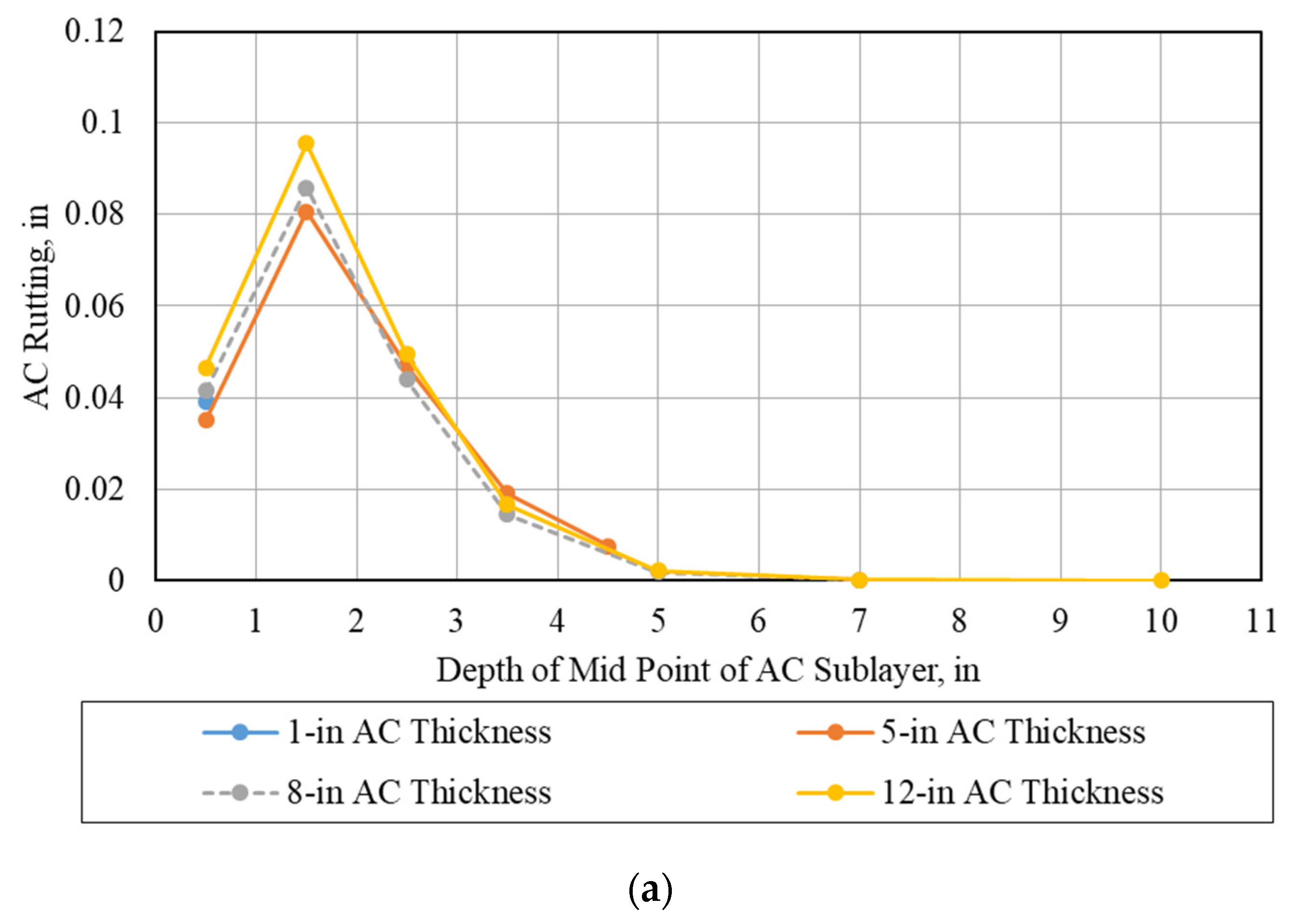
  • ΔAC = Permanent or plastic deformation for the AC layer, in,
  • n = Number of sub-layers,
  • (εp)i = Vertical plastic strain at mid-depth of layer i,
  • Δhi = Thickness of sub-layer i,
  • εr = Computed vertical resilient strain at mid-thickness of sub-layer i for a given load,
  • Kz = Depth correction factor,
  • k1, k2, k3 = Regression coefficients derived from laboratory repeated load permanent deformation test data K1 = −3.35412, K2 = 0.4791, and K3 = 1.5606,
  • β1, β2, β3 = Local calibration coefficients,
  • T = Temperature, °F, and
  • N = Number of repetitions for a given axle load.
Δ P ( S o i l ) = β S 1 K S 1 ε v h S o i l ( ε 0 ε r ) × e ( P N ) β
where
  • Δp(Soil) = Permanent or plastic deformation for the layer/sub-layer, in,
  • ε0 = Intercept determined from laboratory repeated load permanent deformation tests, in/in,
  • εr = Resilient strain imposed in laboratory test to obtain material properties ε0, β, and ρ, in/in,
  • εv = Average vertical resilient or elastic strain in the layer/sub-layer and calculated by the structural response model, in/in,
  • hSoil = Thickness of the unbound layer/sub-layer, in,
  • ks1 = Global calibration coefficient for coarse = 1.673 and fine = 1.35, and
  • βs1 = Local calibration coefficient for rutting in the unbound layers; for the global calibration βs1 = 1.0.
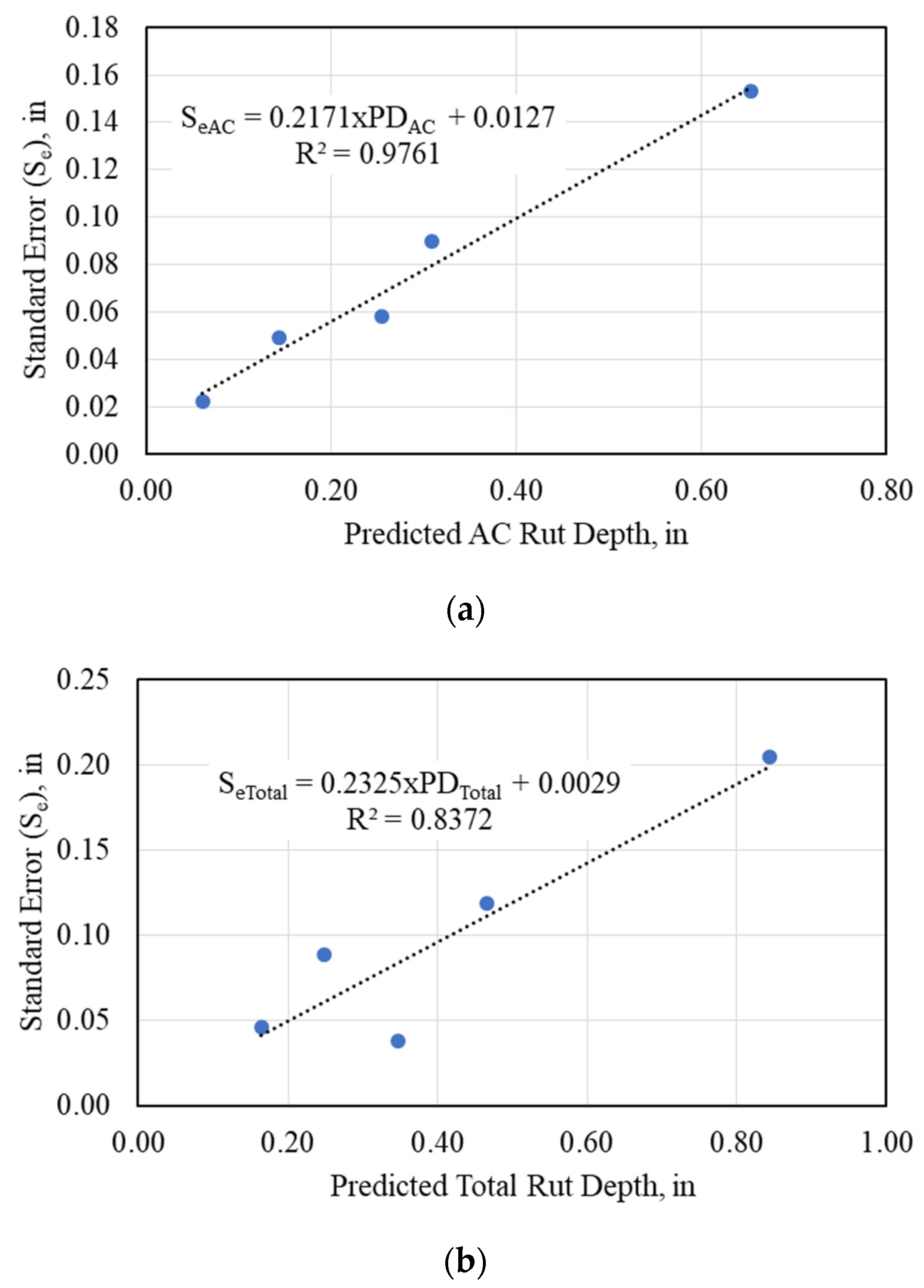
It should be noticed that the approach is based on the calibration process results and the deterministic analysis of the rutting models (i.e., using the expected average value of the pavement distress). In addition, estimating the traffic data, forecasting the climatic data in the future, and presuming the pavement material characterization parameters, which may shift in the construction stage, imply an inherent uncertainty. As a result of these variables and for the design to be accurate, the reliability parameter must be implemented in a consistent and uniform manner to enhance the analysis process [14].
Therefore, the developed simplified M-E design paid attention to this point by allowing the designer to apply reliability into the analysis. Thus, the standard error (Se) for the pavement distress is calibrated based on the investigated data and the developed methodology, as displayed in Figure 11 for AC rutting and total pavement rutting, using Equations (5) and (6), respectively.
R u t t i n g A C R = R u t t i n g ¯ A C + S e A C × Z R
R u t t i n g T R = R u t t i n g ¯ T + S e T × Z R
where
  • R u t t i n g A C R , and R u t t i n g T R = Expected AC, and total pavement rutting at the design reliability level (R),
  • R u t t i n g ¯ A C , and   R u t t i n g ¯ T = Predicted AC, and total rut depth estimated by the correlation models with average input values for all parameters (at 50% design reliability level),
  • SeAC, and SeT = Standard error estimated for the AC, and total rut depth, and
  • ZR = Standard normal deviation for the selected reliability level (R).

3.2.2. Calibration of the Fatigue Cracking Model

The predicted alligator cracking values using the AC fatigue cracking model were highly scattered and shifted horizontally, as presented in Figure 12a. Thus, this model was calibrated by changing the calibration constants, β1, β2, and β3, presented in Equation (6), by trial and error, to reduce the local bias, as illustrated in Figure 12b. Table 3 summarizes the calibration coefficients (β1, β2, and β3) and the statistical goodness of fit parameters.
N f = K t [ β 1 K 1 C ( ε t ) β 2 K 2 ( E ) β 3 K 3 ]
where
  • kt = Thickness correction factor,
  • β1, β2, β3 = Field calibration coefficients,
  • k1, k2, k3 = Material properties determined from regression analysis of laboratory test data: K1 = 0.007566, K2 = 3.9492, and K3 = 1.281,
  • C = Field calibration factor,
  • εt = The critical tensile strain in AC layer, and
  • E = Stiffness of asphalt concrete at specific temperature.
The standard error of the AC fatigue cracking was predicted, as mentioned before, and displayed in Figure 13. Thus, the expected AC fatigue cracking at the required design reliability level can be determined using Equation (7).
F C R = F C ¯ + S e F C × Z R
where
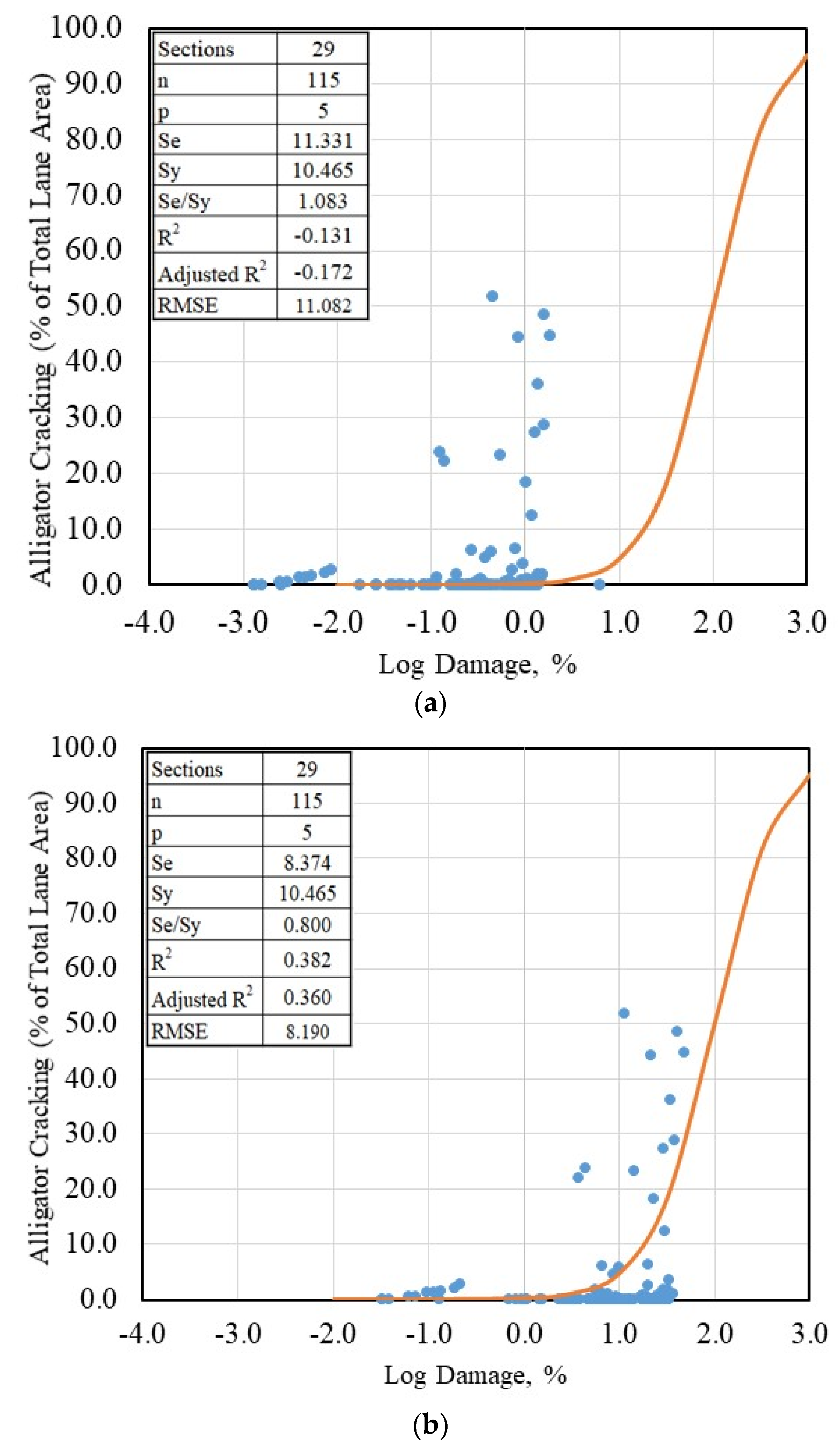
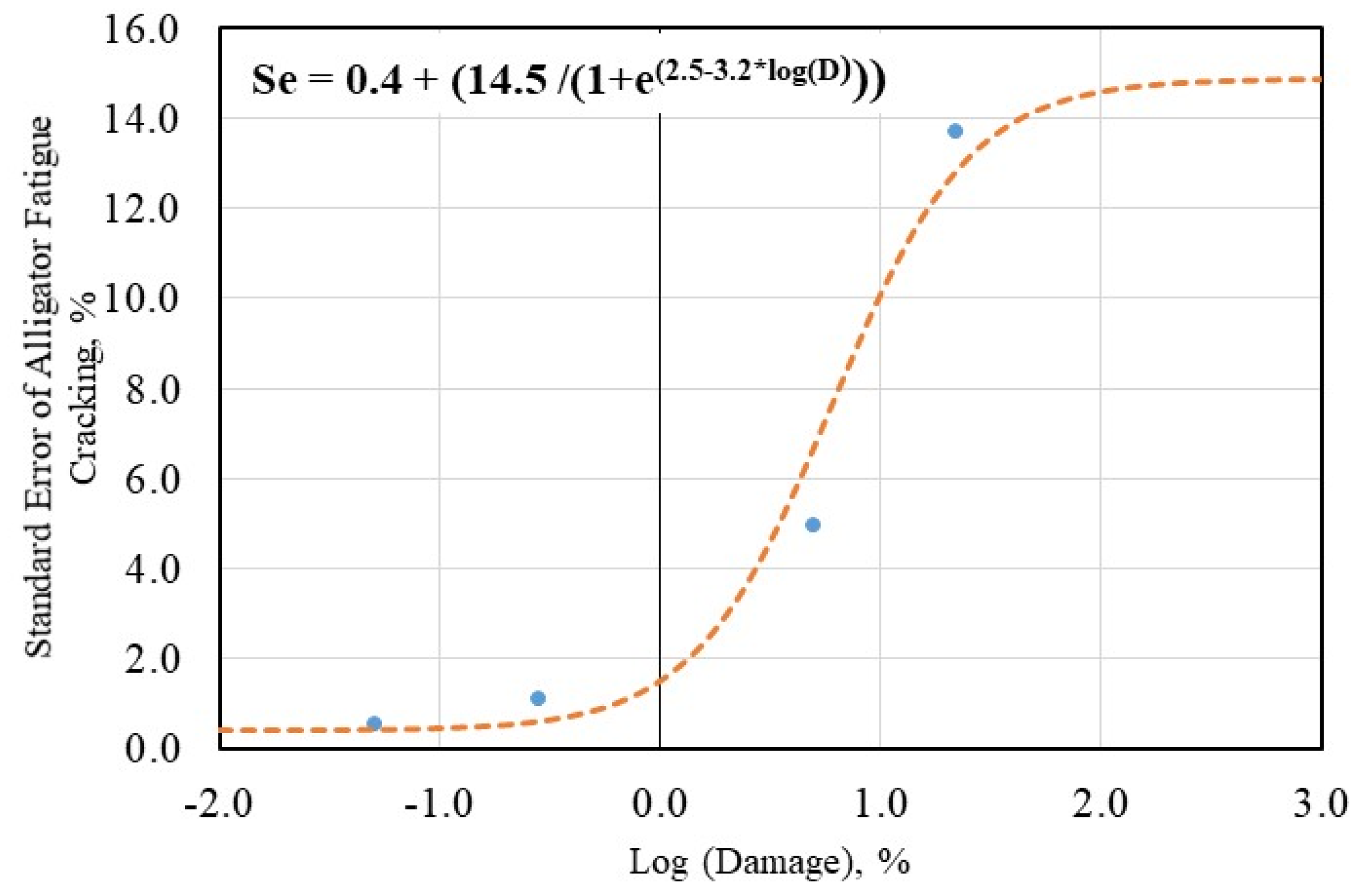
  • FCR = Expected AC “alligator” fatigue cracking at the design reliability level, R,
  • F C ¯ = Predicted AC “alligator” fatigue cracking estimated at 50% design reliability level, and
  • SeFC = Standard error estimated for AC “alligator” fatigue cracking.

3.2.3. IRI Prediction Model

An optimized MEPDG’s IRI model, based on a large LTPP database, was incorporated in the ME-PAVE instead of using the MEPDG’s IRI model. Abdelaziz et al. [55] optimized and calibrated the MEPDG’s IRI prediction model, as described below, based on an extended LTPP database (506 LTPP sections with 2439 data points). This model was implemented in the ME-PAVE.
I R I = I R I 0 + 0.01479 × A g e + 0.00382 × ( F . C ) a l l + 0.00053 ( T . C ) a l l + 0.08941 × S D R U T
where
  • IRI = International Roughness Index at any age, m/km,
  • IRI0 = IRI just after construction, m/km,
  • Age = Pavement age starting from construction or overlay, years,
  • (F.C)all = Fatigue cracking (all severity levels), % of wheel path area,
  • (T.C)all = Transverse cracks length (all severity levels), m/km, and
  • SDRUT = Standard deviation of rutting, mm.
In summary, the proposed ME-PAVE method is a simple but accurate ME pavement design method. It incorporates the hierarchical input levels as the AASHTOWare and builds upon the same concept of transfer functions. It is also a user-friendly method and can be calibrated easily for the local conditions, not only the transfer functions but also the empirical models of the material characterization. Table 4 exhibits a comparison between the AASHTOWare and the ME-PAVE software.

4. Sensitivity Analysis
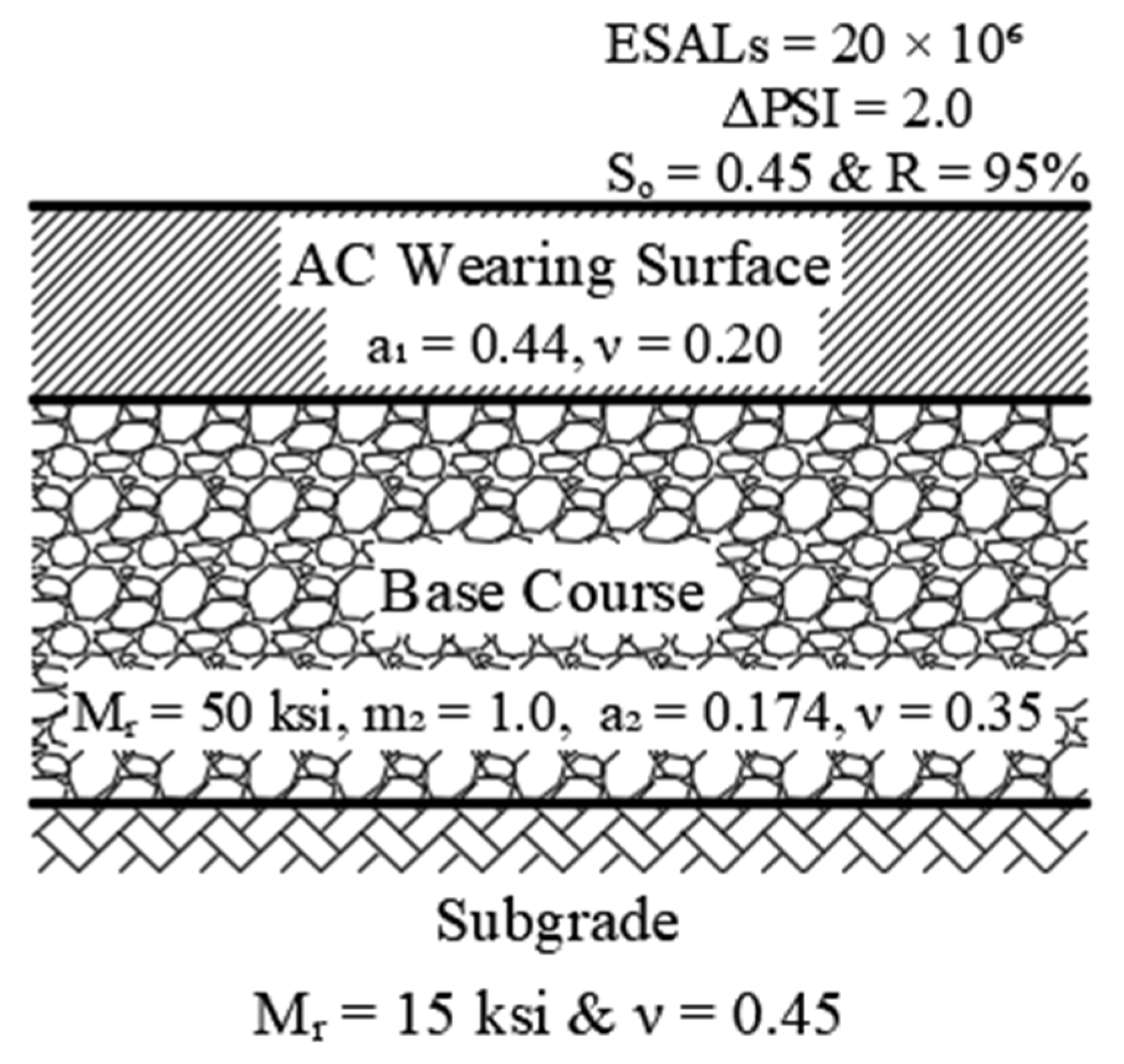
Sensitivity analysis was conducted to evaluate the influence of the input parameters on rutting and alligator fatigue cracking predictions, by using the developed ME-PAVE software. Table 5 summarizes the different input parameters (i.e., ESALs, Traffic Speed, MAAT, AC properties, etc.) used in this study. To conduct the sensitivity analysis, the parameter of interest was changed between its minimum and maximum value, while all other parameters were fixed at the medium level, as displayed in Table 5.
As a result of the conducted sensitivity analysis, it was observed that the AC rut depth increased with increasing the ESALs, tire pressure, MAAT, design reliability, thicknesses of asphalt layers, and asphalt mix volumetric parameters (e.g., void contents and effective asphalt volume), and decreased with increasing the asphalt grade (stiff asphalt) and traffic speed. In addition, the characteristics of underlaying layers had inconsiderable impact on the AC rut depth; while traffic wheel load, design reliability, and the thickness and modulus of unbound layer had significant influence on the rutting value of unbound layers. Moreover, Table 6 summarizes the influence of the design input parameters on the pavement performance. In addition, an example of the influence of AC thickness and modulus on rutting and fatigue cracking is displayed in Figure 14.
Regarding the AC fatigue cracking as presented in Figure 14b, it was noticed that the type of pavement structure (thin or thick pavement) had a significant impact on the AC performance. To this end, the sensitivity analysis results display logical trends, which agree with the known theoretical concepts.

5. Case Study

The ME-PAVE software was used to design and analyze a flexible pavement structure, which consists of an asphalt concrete layer over an-unbound granular layer, as presented in Figure 15. Figure 15 also presents the 1993 AASHTO design input parameters along with the suggested pavement structure. The design input parameters (i.e., traffic data, climatic data, and the properties of pavement materials) are summarized in Table 6. Firstly, the thicknesses of a trial pavement structure were estimated by using the 1993 AASHTO design method, which is implemented in the software. After that, the trial section was analyzed by the software by computing the structural distresses (e.g., AC rutting, total rutting, and AC fatigue cracking) along with the IRI. Eventually, the thicknesses of the AC layer and granular base layer were changed to achieve the minimum safe design, according to the predetermined user criteria.
As presented in Figure 16a, even though the 1993 AASHTO design method provided a thick pavement structure (AC’s thickness more than 4-in (10.2-cm)), the structure is unsafe because the AC fatigue cracking exceeded the 25% limit at 90% reliability, as summarized in Table 7. There are many different alternatives that the designer can select, which become well-defined from the sensitivity analyses as follows:
  • Change the modulus and/or the stiffness of AC layer.
  • Increase the modulus and the thickness of unbound granular layer (base layer).
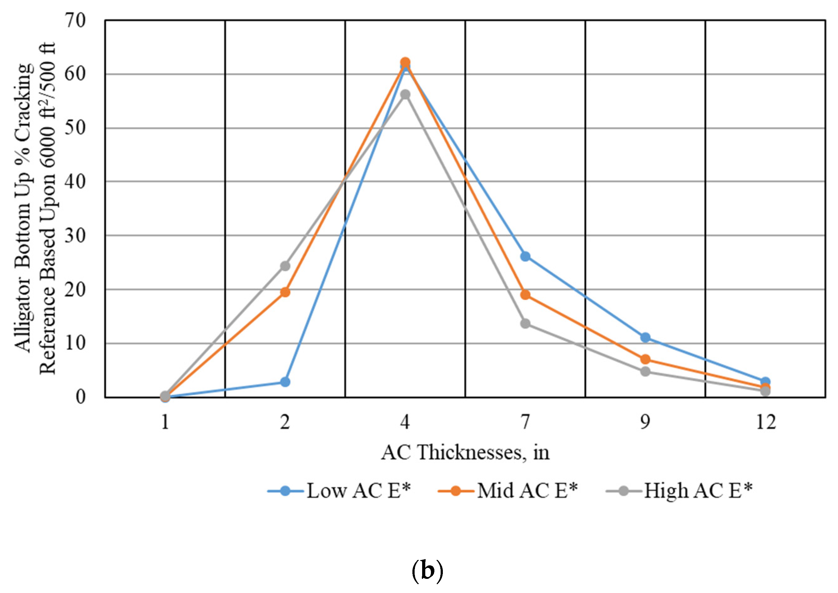
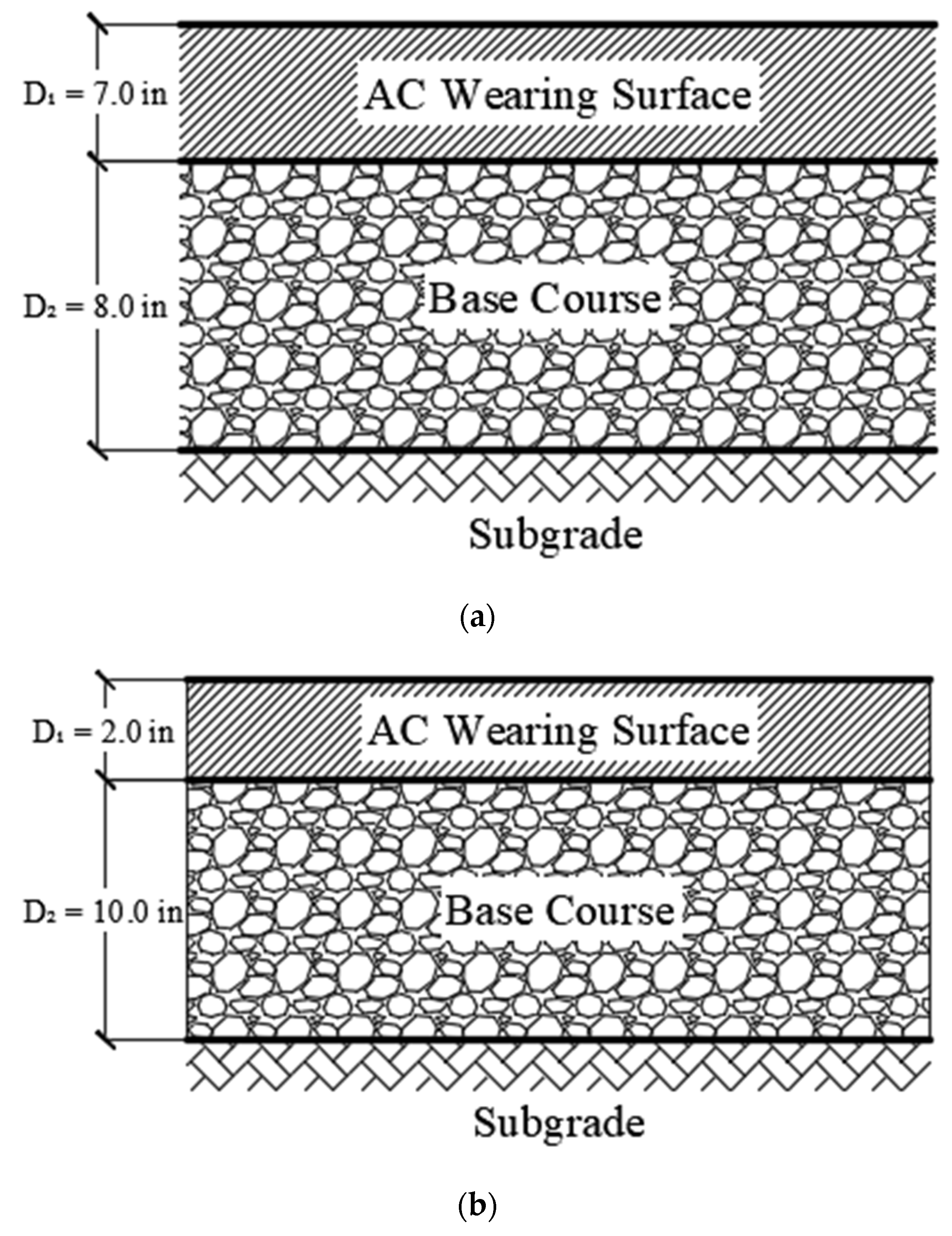
  • Convert the pavement structure from thick to thin structure (AC thickness less than 4-in (10.2-cm)), as illustrated in Figure 16b.
From an economical perspective, the third option (Figure 16b) was chosen, and the software was run one more time to obtain the pavement distresses, as demonstrated in Table 8.
It was found that building a thin pavement structure, with a 2-in (5.1 cm) AC layer over a 10-in (25.4 cm) base layer, is sufficient and safe compared with the thick one. Consequently, a significant amount of pavement construction materials could be saved.

6. Summary and Conclusions

This study presented the development details of a simple but accurate M-E design method for moderate to hot climates. The proposed method relies on the concept of effective temperature and AC dynamic modulus, as well as the transfer functions (used in the AASHTOWare) for performance prediction over the service life, as follows:
  • The structural responses are computed at critical predefined locations in the pavement system by using Axisymmetric FEM. The incorporated FEM in the ME-PAVE provides a chance to consider the nonlinearity and visco-nonlinear analyses in the future.
  • The pavement distress prediction models were calibrated based on LTPP data for wet and dry non-freeze climatic regions.
  • The proposed methodology is implemented into a user-friendly computer code (ME-PAVE) that takes only 40 s to simulate a 20-year analysis period.
  • A sensitivity analysis was conducted to measure the rationality of the predicted distresses, and it was observed that the results are logical and agree with the results of the MEPDG.
    For the rutting model, the simplification of the proposed methodology demonstrated a slight reduction, with acceptable limits in the accuracy of the predicted rut depth values compared to the reported results of current practices (i.e., NCHRP 1-37A and NCHRP 1-40D).
    For the AC “alligator” fatigue cracking model, the calibrated model yielded slightly better prediction compared to the reported results of current practices (i.e., NCHRP 1-40D).

Author Contributions

Conceptualization, methodology, data collection, data curation, data validation and verification, formal analysis, and writing—original draft preparation, A.S.E.-A.; conceptualization, methodology, writing, review, and editing, visualization, and supervision, S.M.E.-B.; conceptualization, writing, review, and editing, visualization, and supervision, A.R.G. All authors have read and agreed to the published version of the manuscript.

Funding

This research received no external funding.

Institutional Review Board Statement

Not applicable.

Informed Consent Statement

Not applicable.

Data Availability Statement

Not applicable.

Conflicts of Interest

The authors declare no conflict of interest.

Abbreviations

Acronyms Descriptions
AASHTOAmerican Association of State Highway Transportation Officials
NCHRPNational Cooperative Highway Research Program
M-E/MEMechanistic-Empirical
ACAsphalt Concrete
FEMFinite Element Module
LTPPLong-Term Pavement Performance
USUnited States of America
MEPDGMechanistic Empirical Pavement Design Guide
NSFNational Science Foundation
DOTdepartments of transportation
HMAHot Mix Asphalt
MLETMulti-Layer Elastic Theory
QRSSQuality-Related Specifications Software
Teff effective temperature
E*effeffective dynamic modulus
ESALEquivalent Single Axle Load
GPSGeneral Pavement Studies
PDPermanent Deformation
SeStandard Error
IRIInternational Roughness Index
MAATMean Annual Air Temperature
σMMATStandard deviation of the mean monthly air temperature

References

  1. U.S. Army Corps of Engineers. The California Bearing Ratio Test as Applied to the Design of Flexible Pavements for Airports. Technical Memory; Number 213-1; Waterways Experiment Station: Vicksburg, MS, USA, 1945. [Google Scholar]
  2. Highway Research Board (HRB). Final Report on Road Test One Maryland; Special Report 4; HRB: Washington, DC, USA, 1952. [Google Scholar]
  3. Highway Research Board (HRB). The WASHO Road Test, Part 1: Design, Construction and Testing Procedure; Special Report 18; HRB: Washington, DC, USA, 1952. [Google Scholar]
  4. Highway Research Board (HRB). The WASHO Road Test, Part 2: Test Data, Analyses Finding; Special Report 22; HRB: Washington, DC, USA, 1955. [Google Scholar]
  5. American Association of State Highway and Transportation Officials (AASHTO). AASHTO Guide for Design of Pavement Structures; AASHTO: Washington, DC, USA, 1961. [Google Scholar]
  6. AASHTO. AASHTO Guide for Design of Pavement Structures; AASHTO: Washington, DC, USA, 1972. [Google Scholar]
  7. AASHTO. AASHTO Guide for Design of Pavement Structures; AASHTO: Washington, DC, USA, 1986. [Google Scholar]
  8. Highway Research Board (HRB). The AASHO Road Test, Report 7; Special Report 61-G; HRB: Washington, DC, USA, 1962. [Google Scholar]
  9. Shell International Petroleum Company Ltd. Shell Pavement Design Manual: Asphalt Pavements and Overlays for Road Traffic; Shell International Petroleum Company Ltd.: London, UK, 1978. [Google Scholar]
  10. LCPC. French Design Manual for Pavement Structures Guide Technique; Laboratoire Central des Ponts et Chaussées: Paris, France, 1994. [Google Scholar]
  11. Powell, W.D.; Potter, J.F.; Mayhew, H.C. The Structural Design of Bituminous Roads; LR 1132; Transport and Road Research Laboratory: Crowthorne, UK, 1984. [Google Scholar]
  12. ARA. Guide for Mechanistic Empirical Design of New and Rehabilitated Pavement Structures; National Cooperative Highway Research Program: Springfield, IL, USA, 2004. [Google Scholar]
  13. ARA. A Manual of Practice; American Association of State Highway and Transportation Officials; ARA: Antioch, IL, USA, 2008. [Google Scholar]
  14. Pereira, P.; Pais, J. Main flexible pavement and mix design methods in Europe and challenges for the development of an European method. J. Traffic Trans. Eng. 2017, 4, 316–346. [Google Scholar] [CrossRef] [Green Version]
  15. Timm, D.H.; Robbins, N.; Tran, C. Flexible Pavement Design-State of the Practice. National Center for Asphalt Technology; Auburn University: Auburn, AL, USA; National Asphalt Pavement Association: Lanham, MD, USA, 2014; Available online: http://www.ncat.us/files/reports/2014/rep14-04.pdf (accessed on 23 September 2021).
  16. PVD. AASHTOWare Pavement ME Design v2.5.5; ARC, Inc.: Boise, ID, USA, 2010; Available online: https://me-design.com/MEDesign/Home.aspx (accessed on 2 June 2020).
  17. Hamdar, Y.S. Effective Incorporation of Asphalt Mixture Properties in the Structural Design of Asphalt Pavements as a Precursor for Implementing Performance-Based Design. Master’s Dissertation, American University of Beirut, Beirut, Lebanon, 2016. Available online: https://scholarworks.aub.edu.lb/bitstream/handle/10938/10968/et-6398.pdf?sequence=1 (accessed on 23 September 2021).
  18. Hamdar, Y.S.; Chehab, G.R. Integrating the Dynamic Modulus of Asphalt Mixes in the 1993 AASHTO Design Method. Transp. Res. Rec. J. Transp. Res. Board 2017, 2640, 29–40. [Google Scholar] [CrossRef]
  19. Pierce, L.M.; McGovern, G. Implementation of the AASHTO Mechanistic-Empirical Pavement Design Guide and Software (No. Project 20-05, Topic 44-06); Transportation Research Record: Washington, DC, USA, 2014; Available online: http://www.trb.org/Publications/Blurbs/170576.aspx (accessed on 23 September 2021).
  20. El-Basyouny, M.M.; Witczak, M.W. Verification of the Calibrated Fatigue Cracking Models for the 2002 Design Guide. J. Assoc. Asph. Paving Technol. 2005, 74, 653–696. [Google Scholar]
  21. Von Quintus, H.L.; Moulthrop, J.S. Mechanistic-Empirical Pavement Design Guide Flexible Pavement Performance Prediction Models: Volume I Executive Research Summary (No. FHWA/MT-07-008/8158-1); Montana Department of Transportation, Research Programs: 2007. Available online: https://rosap.ntl.bts.gov/view/dot/24868 (accessed on 23 September 2021).
  22. Hall, K.D.; Xiao, D.X.; Wang, K.C. Calibration of the mechanistic–empirical pavement design guide for flexible pavement design in Arkansas. Transp. Res. Rec. 2011, 2226, 135–141. [Google Scholar] [CrossRef]
  23. Bayomy, F.; El-Badawy, S.; Awed, A. Implementation of the MEPDG for Flexible Pavements in Idaho (No. FHWA-ID-12-193); Idaho Transportation Department: Boise, ID, USA, 2012. Available online: http://itd.idaho.gov/highways/research (accessed on 23 September 2021).
  24. Caliendo, C. Local Calibration and Implementation of the Mechanistic-Empirical Pavement Design Guide for Flexible Pavement Design. J. Transp. Eng. 2012, 138, 348–360. [Google Scholar] [CrossRef]
  25. Lu, P.; Bratlien, A.; Tolliver, D. North Dakota Implementation of Mechanistic-Empirical Pavement Design Guide (MEPDG) (No. MPC 14-274); Mt. Plains Consort: 2014. Available online: https://rosap.ntl.bts.gov/view/dot/28527 (accessed on 23 September 2021).
  26. Rahman, M.M.; Gassman, S.L. Data collection experience for preliminary calibration of the AASHTO pavement design guide for flexible pavements in South Carolina. Int. J. Pavement Res. Technol. 2018, 11, 445–457. [Google Scholar] [CrossRef]
  27. Li, Q.J.; Wang, K.C.P.; Yang, G.; Zhan, J.Y.; Qiu, Y. Data needs and implementation of the Pavement ME Design. Transp. A Transp. Sci. 2019, 15, 135–164. [Google Scholar] [CrossRef]
  28. Azadi, M.; Nasimifar, S.M.; Pouranian, M.R. Determination of Local Fatigue Model Calibration Used in MEPDG for Iran’s Dry-No Freeze Region. Arab. J. Sci. Eng. 2012, 38, 1031–1039. [Google Scholar] [CrossRef]
  29. Tarefder, R.; Rodriguez-Ruiz, J.I. Local Calibration of MEPDG for Flexible Pavements in New Mexico. J. Transp. Eng. 2013, 139, 981–991. [Google Scholar] [CrossRef]
  30. Elshaeb, M.; El-Badawy, S.M.; Shawaly, A.E.-S. Development and Impact of the Egyptian Climatic Conditions on Flexible Pavement Performance. Am. J. Civ. Eng. Archit. 2014, 2, 115–121. [Google Scholar] [CrossRef] [Green Version]
  31. Sadek, H.A.; Masad, E.A.; Sirin, O.; Al-Khalid, H.; Sadeq, M.A.; Little, D. Implementation of mechanistic-empirical pavement analysis in the State of Qatar. Int. J. Pavement Eng. 2013, 15, 495–511. [Google Scholar] [CrossRef]
  32. Ma, H.; Wang, D.; Zhou, C.; Feng, D. Calibration on MEPDG Low Temperature Cracking Model and Recommendation on Asphalt Pavement Structures in Seasonal Frozen Region of China. Adv. Mater. Sci. Eng. 2015, 2015, 830426. [Google Scholar] [CrossRef] [Green Version]
  33. Alqaili, A.H.; Alsoliman, H.A. Preparing Data for Calibration of Mechanistic-Empirical Pavement Design Guide in Central Saudi Arabia. Technol. Int. J. Urban Civ. Eng. 2017, 11, 248–255. [Google Scholar]
  34. Chehab, G.R.; Chehade, R.H.; Houssami, L.; Mrad, R. Implementation Initiatives of the Mechanistic-Empirical Pavement Design Guide in Countries with Insufficient Design Input Data—The Case of Lebanon. In Advancement in the Design and Performance of Sustainable Asphalt Pavements; Springer Science and Business Media LLC: Berlin, Germany, 2018; pp. 147–167. [Google Scholar]
  35. Eyada, S.O.; Celik, O.N. A Plan for the implementation of Mechanistic-Empirical Pavement Design Guide in Turkey. Pertanika J. Sci. Technol. 2018, 26, 4. [Google Scholar]
  36. Chhade, R.H.; Mrad, R.; Houssami, L.; Chehab, G. Formulation of Traffic Inputs Required for the Implementation of the M-E PDG in Data-Scarce Regions: Lebanon Case Study. J. Mater. Civ. Eng. 2018, 30, 04018198. [Google Scholar] [CrossRef]
  37. El-Ashwah, A.S.; Mousa, E.; El-Badawy, S.M.; Abo-Hashema, M. Advanced characterization of unbound granular materials for pavement structural design in Egypt. Int. J. Pavement Eng. 2020, 1–13. [Google Scholar] [CrossRef]
  38. Trautvain, A. Analysis of the Influence of the Qualitative Composition of the Asphalt-Concrete Mixture on the Main Performance Characteristics of Asphaltic Concrete Pavement. Constr. Mater. Prod. 2020, 2, 17–23. [Google Scholar] [CrossRef]
  39. El-Ashwah, A.S.; Awed, A.M.; El-Badawy, S.M.; Gabr, A.R. A new approach for developing resilient modulus master surface to characterize granular pavement materials and subgrade soils. Constr. Build. Mater. 2019, 194, 372–385. [Google Scholar] [CrossRef]
  40. Awed, A.M.; Aboelela, A.E.; El-Ashwah, A.S.; Allam, M.; El-Badawy, S.M. Improvement of unbound granular pavement layers and subgrade with cement dust in Egypt. Int. J. Pavement Res. Technol. 2020, 13, 621–629. [Google Scholar] [CrossRef]
  41. Moulthrop, J.; Witczak, M. NCHRP Report 704: A Performance-Related Specification for Hot-Mixed Asphalt; Transportation Research Board: Washington, DC, USA, 2011. [Google Scholar]
  42. Arisha, A.M.; Gabr, A.R.; El-Badawy, S.M.; Shwally, S.A. Performance Evaluation of Construction and Demolition Waste Materials for Pavement Construction in Egypt. J. Mater. Civ. Eng. 2018, 30, 04017270. [Google Scholar] [CrossRef]
  43. Ezzat, H.; El-Badawy, S.; Gabr, A.; Zaki, S.; Breakah, T. Predicted performance of hot mix asphalt modified with nano-montmorillonite and nano-silicon dioxide based on Egyptian conditions. Int. J. Pavement Eng. 2020, 21, 642–652. [Google Scholar] [CrossRef]
  44. Mousa, E.; Azam, A.; El-Shabrawy, M.; El-Badawy, S. Laboratory characterization of reclaimed asphalt pavement for road construction in Egypt. Can. J. Civ. Eng. 2017, 44, 417–425. [Google Scholar] [CrossRef] [Green Version]
  45. Mousa, E.; El-Badawy, S.; Azam, A. Effect of reclaimed asphalt pavement in granular base layers on predicted pavement performance in Egypt. Innov. Infrastruct. Solut. 2020, 5, 1–18. [Google Scholar] [CrossRef]
  46. Shiha, M.; El-Badawy, S.; Gabr, A. Modeling and performance evaluation of asphalt mixtures and aggregate bases containing steel slag. Constr. Build. Mater. 2020, 248, 118710. [Google Scholar] [CrossRef]
  47. El-Badawy, S.M.; Jeong, M.G.; El-Basyouny, M. Methodology to Predict Alligator Fatigue Cracking Distress Based on Asphalt Concrete Dynamic Modulus. Transp. Res. Rec. J. Transp. Res. Board 2009, 2095, 115–124. [Google Scholar] [CrossRef]
  48. El-Basyouny, M.; Jeong, M.G. Effective Temperature for Analysis of Permanent Deformation and Fatigue Distress on Asphalt Mixtures. Transp. Res. Rec. J. Transp. Res. Board 2009, 2127, 155–163. [Google Scholar] [CrossRef]
  49. El-Basyouny, M.; Jeong, M.G. Probabilistic Performance-Related Specifications Methodology Based on Mechanistic–Empirical Pavement Design Guide. Transp. Res. Rec. J. Transp. Res. Board 2010, 2151, 93–102. [Google Scholar] [CrossRef]
  50. El-Badawy, S.; Bayomy, F.; Fugit, S. Traffic Characteristics and Their Impact on Pavement Performance for the Implementation of the Mechanistic-Empirical Pavement Design Guide in Idaho. Int. J. Pavement Res. Technol. 2012, 5, 386–394. [Google Scholar]
  51. National Cooperative Highway Research Program Project 9-22. Beta Testing and Validation of HMA PRS; Washington, DC, USA, 2011. Available online: https://apps.trb.org/cmsfeed/TRBNetProjectDisplay.asp?ProjectID=958 (accessed on 23 September 2021).
  52. Chen, D.H.; Zaman, M.; Laguros, J.; Soltani, A. Assessment of Computer Programs for Analysis of Flexible Pavement Structure. Transp. Res. Rec. 1995, 1482, 123–133. [Google Scholar]
  53. Duncan, J.M.; Monismith, C.L.; Wilson, E.L. Finite Element Analysis of Pavements. Highw. Res. Rec. 1968, 228, 18–33. [Google Scholar]
  54. AASHTO. Guide for the Local Calibration of the Mechanistic-Empirical Pavement Design Guide; American Association of State Highway and Transportation Officials: Washington, DC, USA, 2010. [Google Scholar]
  55. Abdelaziz, N.; El-Hakim, R.T.A.; El-Badawy, S.M.; Afify, H.A. International Roughness Index prediction model for flexible pavements. Int. J. Pavement Eng. 2018, 21, 88–99. [Google Scholar] [CrossRef]
  56. Amin, I.; El-Badawy, S.M.; Breakah, T.; Ibrahim, M.H.Z. Laboratory evaluation of asphalt binder modified with carbon nanotubes for Egyptian climate. Constr. Build. Mater. 2016, 121, 361–372. [Google Scholar] [CrossRef]
Figure 1. The development of flexible pavement design methods [1,2,3,4,5,6,7,8,9,10,11,12,13,14].
Sustainability 13 10760 g001
Figure 2. Design/Analysis process of the developed methodology.
Sustainability 13 10760 g002
Figure 3. (a) Input parameters for traffic, design criteria, and climate data. (b) Required properties of the AC materials. (c) Required properties of the unbound granular materials and subgrade soils.
Sustainability 13 10760 g003aSustainability 13 10760 g003b
Figure 4. Computed vertical and horizontal strains at different locations for vertical boundary condition: (a) tensile strain vs. depth and (b) vertical strain vs. depth, and for horizontal boundary condition: (c) tensile strain vs. depth and (d) vertical strain vs. depth (N.B. 1-in = 2.54 cm).
Sustainability 13 10760 g004aSustainability 13 10760 g004b
Figure 5. Selected aspect ratio for the pavement structures.
Sustainability 13 10760 g005
Figure 6. Flow chart for defining the domain of pavement structure and FEM process.
Sustainability 13 10760 g006
Figure 7. Comparison between the developed FEM and the MLEA for a Two-Layered System: (a) horizontal tensile strains and (b) vertical compressive strains (N.B. 1-in = 2.54 cm).
Sustainability 13 10760 g007aSustainability 13 10760 g007b
Figure 8. Verification of linearity with tensile and compressive vertical strains for a three-layer system: (a) tensile strain at the bottom of AC layer and (b) compressive strain at the top of subgrade (N.B. 1 kips = 4.448 kN, 1-in = 2.54 cm).
Sustainability 13 10760 g008aSustainability 13 10760 g008b
Figure 9. Frequency distribution of measured total rut depths and AC “Alligator” fatigue cracking: (a) rutting distress and (b) AC “alligator” fatigue cracking (N.B. 1-in = 2.54 cm).
Sustainability 13 10760 g009
Figure 10. Relationship between measured and predicted total rut depth values (a) before calibration and (b) after the calibration process (N.B. 1-in = 2.54 cm).
Sustainability 13 10760 g010aSustainability 13 10760 g010b
Figure 11. Standard error of estimate for predicted rutting (a) AC layer (b) Total pavement structure (N.B. 1 in = 2.54 cm).
Sustainability 13 10760 g011
Figure 12. Relationship between the Log damage and predicted AC fatigue cracking (a) before calibration and (b) after the calibration process.
Sustainability 13 10760 g012
Figure 13. Standard error of estimate for fatigue cracking of AC layer.
Sustainability 13 10760 g013
Figure 14. Pavement distress at different AC thicknesses: (a) AC rutting and (b) AC fatigue cracking (N.B. 1-in = 2.54 cm).
Sustainability 13 10760 g014aSustainability 13 10760 g014b
Figure 15. Typical cross-section of the pavement (N.B. MrBase = 50 ksi (344.74 MPa) and MrSubgrade = 15 ksi (103.4 MPa)).
Sustainability 13 10760 g015
Figure 16. Pavement Design Sections: (a) the 1993 AASHTO design section and (b) the suggested pavement structure using ME-PAVE (N.B. 1-in = 2.54 cm).
Sustainability 13 10760 g016
Table 1. The properties of the pavement structure.
LayerModulus, ksi (MPa)Depth, in (cm)
AC layer50, 250, 450, and 1000
(344.7, 1723.7, 3102.64, and 6894.75)
2, 6, 12, and 18
(5.08, 15.24, 30.48, and 45.72)
Subgrade 4, 10, and 20
(27.6, 69, and 137.9)
-
Table 2. Calibration coefficient and statistical values of the optimization process.
ParameterCalibration CoefficientME-PAVEMEPDG
1-37A1-40D
Calibration Coefficientsβr10.801.01.0
βr20.7151.01.0
βr30.7151.01.0
βrGB0.111.01.0
βrSG1.051.01.0
Statistical Goodness of fit parametersSe/Sy0.8340.8220.818
R20.3170.3990.577
Table 3. Calibration coefficients and statistical values of the optimization process.
ParametersCalibration CoefficientsME-PAVEMEPDG
1-37A1-40D
Calibration Coefficientsβ11.01.01.0
β20.861.01.0
β30.931.01.0
Statistical goodness of fit parametersSe/Sy0.8000.9470.815
R20.382-0.275
Table 4. Comparison of the AASHTOWare and ME-PAVE.
ParameterAASHTOWareME-PAVE
User Friendly SoftwareYesYes
Pavement Type
New Pavement Design (Flexible or Rigid)YesFlexible Only
Rehabilitation: AC over Fractures Portland Cement Concrete (PCC) Slab (Crack and Seat, Break and Seat, Rubblized)YesNo
Inputs
Input Level HierarchyYes Yes
Traffic
Axle Load Spectra YesNo
18-Kips ESALsYesYes
Traffic Distribution (Hourly, Daily, Monthly)YesNo
Traffic WanderYesNo
Traffic Speed (Rate of Loading)YesYes
Special Vehicle Damage AnalysisYesYes
Climate
Hourly Climatic Data (Temperature, Precipitation, Wind Speed, Percentage Sunshine, and Relative Humidity)YesNo,
Average Yearly Climatic Data and σMMAT
Groundwater Table DepthYesNo
Surface Shortwave Absorptivity,YesNo
InfiltrationYesNo
Drainage Path Length,YesNo
Cross Slope.YesNo
Distress
AC and Unbound Materials RuttingYesYes
Alligator Fatigue CrackingYesYes
Longitudinal Fatigue CrackingYesNo
Transverse CrackingYesNo
International Roughness Index, IRIYesYes
Design Reliability for Each Distress YesYes
Models Calibration
Nationally Calibrated/Validated ModelsYes, based on LTPP database for freeze to high climateYes, based on LTPP database for Moderate to high climate
Analysis Time for 20 years analysis periodAbout 10 min Only 40 s
Table 5. Design input parameters for the sensitivity analysis study.
Very
Low
Low
(L)
Medium (M)Medium
High
High
(H)
Very
High
Traffic Levels (×105 ESALs)22015050010001600
Operating
Speed, mph (km/h)
2
(3.2)
25
(40.2)
45
(72.4)
-60
(96.6)
AC Thickness, in (cm)1
(2.5)
2
(5.1)
4
(10.2)
12
(30.5)
AC
Gradation [56]
Low MixMed. MixHigh Mix
% P¾″ 95
% P3/8″ 76.5
% P#4 49.1
% P#200 4.8
AC GradeAi 9.224 [56]10.6508 [13]10.808 [43]
VTSi −3.065 [56]−3.5537 [13]−3.598 [43]
AC Air Voids, % 47 10
Vbe, % 811 15
Base
Layer
Thickness, in
(cm)
4
(10.16)
10
(25.4)
25
(63.5)
Modulus, ksi
(MPa)
20
(137.9)
30
(206.8)
38.5
(265.5)
50
(344.7)
60
(413.7)
Subgrade
Modulus, ksi (MPa)
3
(20.7)
8
(55.2)
15
(103.4)
30
(206.8)
Climate
Conditions [30]
Cities Alex.Cairo Aswan
Parameters
MAAT, °F (C) 71.34
(21.86)
74.42
(23.57)
76.06
(24.48)
σMMAT, °F 8.3311.60 12.39
Wind Speed, mph (km/h) 10.68
(17.19)
6.39
(10.28)
5.36
(8.63)
Sunshine (%) 88.8990.09 96.08
Rain, inch (cm) 9.15
(23.24)
2.75
(7.0)
0.38
(0.97)
Note: The computer runs were conducted using the “Medium” input level for all other parameters except the parameter of interest, which is changed between the other levels.
Table 6. Results of sensitivity analysis for different design input parameters.
Design ParametersRutting DepthFatigue Cracking
ACBaseSubgradeThin AC
(dAC ≤ 4” (10.2-cm))
Thick AC
(dAC > 4” (10.2-cm))
Traffic Level (ESALs)+==++
AC Thickness+--+ 1- 1
HMA PropertiesAsphalt Grade-=+=++-
%Va+==++
%Vbe+==--
Climatic Conditions (MAAT)+==-+
Base Thickness=+--=-
Base Modulus=+----
Subgrade Modulus=+=---
Operating Speed-==+-
Wheel Load=+++-
Tire Pressure+=+=++
Design Reliability+++++
+ Increase, - Decrease, = No Effect, =+ Slightly Increase, and =- Slightly Decrease. 1, as presented in Figure 14b.
Table 7. Design input parameters of the case study’s analyzing process.
Traffic Data
Traffic Levels (106 ESALs)20
Tire Pressure, psi (kPa)120 (827.4)
Wheel Load, kips (kN)9 (40)
Operating Speed, mph (km/h)60 (96.6)
Pavement Layers Properties (Level 2)
AC layer Gradation [56]% P¾”95
% P3/8”76.5
% P#449.1
% P#2004.8
AC Grade [13]Ai10.980
VTSi−3.680
AC in place Air Voids, % 7
Vbe, %11
Base layer modulus, ksi (MPa)50 (344.7)
Subgrade layer modulus, ksi (MPa)15 (103.4)
Climate Conditions [30] CitiesCairo
Parameters
MAAT, °F (C)74.42 (23.6)
σMMAT (°F)11.60
Wind Speed, mph (km/h)6.39 (10.3)
Sunshine (%)90.09
Rain, in (cm)2.75 (7.0)
Table 8. Summary of the case study analyses.
Parameters1993 Designed SectionAlternative SectionDesign Criteria
AC Rutting, in (cm)Mean0.110 (0.279)0.084 (0.21)
at 90% R0.157 (0.4)0.124 (0.315)0.20-in (0.51)
Total Rutting, in (cm)Mean0.189 (0.48)0.261 (0.663)
at 90% R0.251 (0.638)0.343 (0.871)0.5-in (1.27)
AC Fatigue Cracking, %Mean20.7857.335
at 90% R48.02624.09325%
IRI Distress, in/mile (m/km)Mean90.943 (1.44)88.133 (1.39)
at 90% R96.930 (1.53)94.31 (1.49)120 (1.89)
Publisher’s Note: MDPI stays neutral with regard to jurisdictional claims in published maps and institutional affiliations.

