1. Introduction
A prominent technology today for the energy conversion of fossil fuels, such as natural gas (NG) and oil, are the gas turbine systems. These machines reach high energy conversion efficiencies due to technological progress and advanced materials in their design and construction. Nevertheless, the associated environmental impact of these machines plays a key role in climate change, highlighting the necessity of energy efficiency improvement policy in power plants and energy policies overall [
1]. Currently, such policies motivate governments to improve the efficiency of gas turbines by further recuperating thermal energy from the exhaust gasses to produce steam and drive a steam turbine [
2]. However, this kind of relatively high-investment cost of solutions force private companies to seek cheaper solutions [
3,
4].
In a simple gas turbine system, the temperature and pressure of the ambient air increases by passing through the compressor. After mixing with the fuel and the ignition, the high-pressure combustion products reach the highest operating temperature. The hot combustion product (gases) is expanded in the turbine, moving the rotating blades, and consequently rotating the turbine shaft to provide power for rotating the compressor and the generator [
5]. The amount of required power for the compressor depends on the inlet volumetric flow of the air; more power is required to compress the same mass flow of air of lower density to a given outlet pressure.
A means to decrease the inlet air temperature and boost the turbine output recommended by most gas turbine manufacturers is the use of cooling equipment. Cooling equipment includes evaporative coolers, fogging, and chillers that significantly increase the capital cost of the plant. Although cooling systems improve operation, their efficacy is highly dependent on ambient temperature [
6] and humidity. Steam injection into the combustion chamber for power enhancement is another method, but it requires large quantities of demineralized water, and is linked to combustion and other operational challenges.
Another measure to increase the generated power of gas turbine systems is the compressed air injection (CAI), i.e., the injection of additional pressurized air into the combustion chamber or at the compressor outlet. This additional air flow requires then more fuel to maintain the inlet temperature of the expander. Nevertheless, in such applications, the fuel increase pales in comparison to the gas turbine power increase. The significant power increase is due to the higher mass flow in the turbine, and consequently, the increased work generated in comparison to the compressor’s required work. This leads to an overall enhancement of the thermal efficiency of the gas turbine. Nakhamkin et al. [
7] proposed injecting compressed air in a highly efficient electrically driven compressor upstream of the combustion chamber. The air can be injected through the ports of steam injection that are already available in some commercial gas turbines. CAI also helps to increase the lifetime of the gas turbine by reducing the inlet temperature of the turbine without a reduction in the power generation. Akita et al. showed that the reduction of firing temperature with air injection by approximately 110 °C increases the maintenance intervals and reduces the maintenance costs by a factor of two in both cases [
8]. Typically, up to 10% of a gas turbine’s airflow at ISO conditions (temperature = 15 °C, relative humidity = 60%, and pressure = 101.3 kPa) can be used for injection purposes. However, avoiding compressor surge and the torque limit of the shaft restrict the maximum retrieved air at any given ambient temperature. An electrical motor or an efficient reciprocating engine may drive an intercooled compressor that compresses ambient air and adds it to the compressor outlet [
9]. Internal combustion engines are less sensitive to temperature and humidity, maintaining their nominal power output and efficiency over a broader range of ambient conditions. Hence, some companies designed a series of standardized building block modules which can be connected together to operate at high injection air flows [
10]. Combined diesel-engine gas turbine systems enable distributed power generation plants to attain high thermal efficiencies while enjoying the operational advantages of both diesel engines and gas turbines [
11]. Abudu et al. evaluated the implication of the steady-state injection of compressed air into two multi-spool gas turbines for power enhancement. The steady-state analysis demonstrated that with an 8% flow injection, a power increase of at least 16% is obtained [
12]. Gas turbines also play a key role in synchronous power generation and back-up systems for intermittent renewable systems. Igie et al. [
13] considered the extraction of compressed air from a single-shaft gas turbine to store energy when surplus power is available and then the reinjection of the pressurized air at peak demand. CAI can constitute thus an alternative solution for energy storage, required by most renewable power sources.
Although a wide range of fuels can be used in gas turbines, compressed natural gas is the most common fuel used. Natural gas is transported through pipelines over long distances. The pressure of the natural gas must be significantly decreased before it is supplied to the combustion chamber of the gas turbine system. The pressure reduction of the natural gas that usually occurs in throttling valves is accompanied by substantial energy and exergy losses [
14].
Today, many researchers study energy recovery devices for the decompression of high-pressure natural gas. The amount of energy that can be recovered depends on various parameters including both operating conditions (pressure difference, temperature, and mass flow) and design parameters (efficiency, capacity, performance map, etc.) [
15,
16,
17,
18,
19]. Furthermore, the quality of NG (in terms of hydrate formation) is also crucial [
14]. Many authors, such as Morgese et al. [
20], propose an optimization design procedure of a turboexpander by considering fluid dynamic and technical requirements. Recovery of waste energy of the gas stations can also be used for both producing power and freshwater with a potentially substantial effect on the reduction of greenhouse gases and air emissions [
21]. Golchoobian et al. [
22] investigated the feasibility of using a turboexpander coupled with a refrigeration cycle to decrease the inlet temperature of air and increase the generated power. Although many studies evaluate waste energy recovery from pressure-reducing stations and air injection into the combustion chamber separately, the combined use of waste energy to inject air into gas turbine combustion chambers is still missing. This paper aims to address this research gap with energy and exergy analyses of a hybrid system of a gas turbine including a natural gas turboexpander and air injection for performance enhancement. Lastly, since the capacity and operating conditions of pressure-reducing stations in power plants vary moderately, important parameters and their effects are studied in this work as well.
3. Methodology
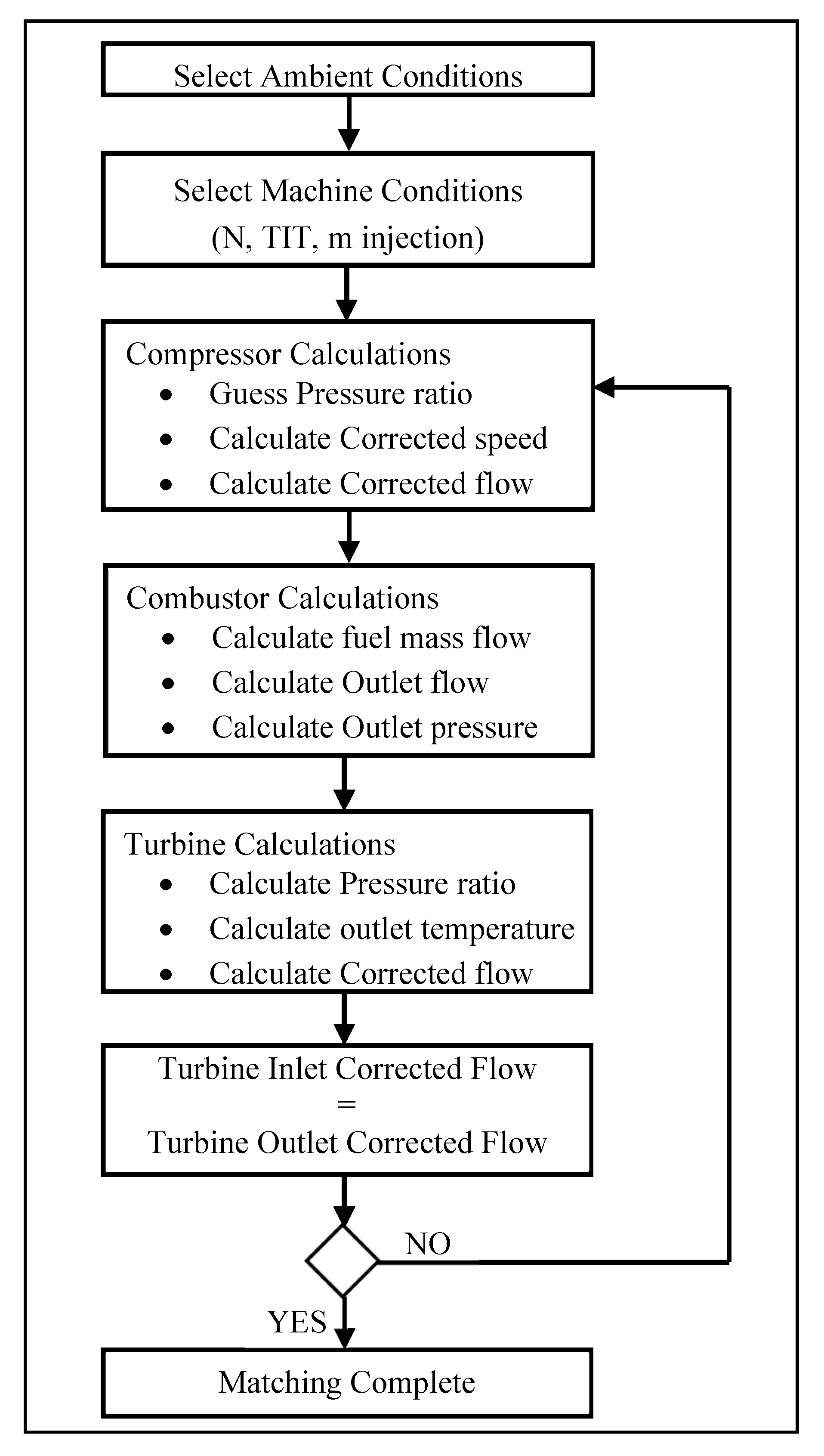
To determine the effects of the air-injection system on the performance of the chosen gas turbine, a computer code was developed in the engineering equation solver (EES). The calculation procedure of the EES code is summarized in
Figure 2. This code calculates the thermodynamic properties and off-design performance of the gas turbine with and without the high-pressure injection system. Another model was simulated using the Thermoflex software to validate the in-house code results. Operational compatibility between the turbine and the compressor of the gas turbine (matching calculations) depends on mass flow compatibility, pressure ratio (work), and rotational speed [
24]. The characteristic curves of mass flow, pressure ratio, and efficiency with rotational speed of the compressor, turbine, and combustion chamber were obtained for the gas turbine model V94.2. It should be noted that the demonstrated flow chart has been developed on the assumption that the turbine inlet temperature (TIT) remains constant. This assumption depends on the control system mode of the gas turbine, and it can be adjusted for other GT control modes. Considering constant TIT and compatibility of speed and flow for a single-shaft machine, the pressure ratio and other performance characteristics of the gas turbine were determined.
In this study, the effect of the proposed air-injection system was studied on the heavy-duty gas turbine of Siemens V94.2, a model widely used in power plants. V94.2 is a single-shaft gas turbine with a rated power of 162 MW. This turbine incorporates a 16-stage compressor, two large silo-type combustion chambers, and a four-stage turbine. Performance data (including the compressor and turbine data) for the simulation were found in various references and official original equipment manufacturer (OEM) websites of Siemens and Alstom [
25,
26,
27,
28]. The design performance characteristics of the gas turbine are presented in
Table 1. Calculated performance parameters with the EES code, including power and efficiency at various ambient temperatures, agree with published OEM data with an accuracy of more than 98%.
The pressure ratio of the gas turbine is a function of the compressor pressure ratio and the pressure drop within the combustor.
where
and
are the pressures at the inlet and outlet of the combustor, respectively. The mass flow that passes through the turbine is equal to the outlet mass flow of the compressor plus the fuel flow and the additional compressed air:
The turbine and compressor shafts were coupled together to assure compatible rotational speed.
In most gas turbines, the TIT is constant during the operation due to metallurgical limitations. Although there are various definitions and positions to measure the TIT (T
03), in this study it was considered constant so that for given ambient conditions, the square root of the temperature ratio was constant as well. Moreover, the non-dimensional flow term expresses the compatibility of the flow between the compressor and the turbine as follows:
where
is the inlet mass flow of the compressor,
is the inlet mass flow of the turbine,
is the ambient temperature at the inlet of the compressor,
is the pressures at the inlet of the compressor. The adiabatic work of the compressor can be calculated with Equation (5):
where
is the specific heat capacity of the air at constant pressure and
is the outlet temperature of the compressor.
The actual compressor outlet temperature (
, considering its isentropic efficiency (
, can be estimated with the following equation:
where
is the compressor efficiency and
the air-specific heat ratio.
The outlet pressure of the combustion chamber (
is also calculated from the compressor’s delivery pressure (
and the pressure drop of the air in the combustor (
. For most available combustors it is in the range of 0.03–0.05 of the inlet pressure [
29].
With constant blade dimensions and negligible changes in efficiency, higher inlet mass flow will lead to an off-design operation of the turbine. A similar equation to the compression process is used for the calculation of the turbine’s expansion work (
by considering the total mass flow of the gas calculated with Equation (2):
where
. is the specific heat of the exhaust gas and
is the temperature at the outlet of the turbine.
The actual turbine outlet temperature (
. can be estimated with Equation (9), considering the isentropic efficiency of the turbine
:
The net or useful work of the gas turbine can be obtained by subtracting the consumed work of the compressor from the produced work of the turbine.
where
is the mechanical efficiency of the gas turbine.
Similar equations can be used to determine the mass flow of the additional compressed air in the turboexpander at different conditions.
where
. is the combined mechanical efficiency,
. the produced work of the turboexpander, and
the shaft power of the air-injection compressor.
In this study, the effect of various parameters on the mass flow of injected air were investigated. The mass flow of the fuel that expands in the turboexpander plays a key role on the mass flow of the injected air. Based on OEM data of several industrial gas turbine models, up to 5% of the main gas turbine inlet flow can be injected into the combustion chamber safely [
30].
Table 2 presents selected parameters used to model the proposed system.
To evaluate the environmental performance of the proposed system and compare it to that of a conventional system, the amount of generated CO
2, CO, and NOx have been calculated. The emitted CO
2 was calculated using the combustion and equilibrium reactions. Empirical relations proposed in [
31] are used to determine the emission of CO and NOx, using adiabatic flame temperature in the primary zone of the combustion chamber as follows [
32]:
where
is a dimensionless temperature,
is a dimensionless pressure,
is the fuel to air equivalent ratio, and
is the H/C atomic ratio. Parameters A,
, β, λ, a
i, b
i, and c
i are constants, depending on
. and
, available in [
33]. Accordingly, by using adiabatic flame temperature, the produced CO and NOx can be estimated based on the following empirical equations in grams per kilogram of fuel flow:
where P
2 is the pressure at the inlet of the combustor,
is the dimensionless pressure loss in the combustion chamber, and
is the residence time in the combustion zone (considered constant at 0.02 s).
As mentioned, the validation of the energy model of the gas turbine with injection was carried out with the Thermoflow software—commercially available thermal engineering software for analyzing the performance of thermodynamic cycles. In this validation process, the total pressure loss of intake and exhaust were assumed to be 10 and 5 mbar, respectively. The air compressor was fed with power from the natural gas turboexpander. A schematic of the Thermoflow model is shown in
Figure 3.
The validation results are reported in
Table 3, where the gas turbine power and efficiency were calculated with and without CAI. It is seen that there is generally good agreement between the EES code and the Thermoflow results, with acceptable errors for both power and efficiency.
By applying the laws of thermodynamics within component k, exergy destruction is obtained, which is a relation between the fuel and product exergy as follows [
34]:
where
and
. are the fuel and product exergy of each component, respectively, and
is the exergy destruction within component k. Exergy loss is not defined at the component level, as it is only relevant for the overall process [
35,
36,
37]. All exergy calculations of streams are based on the sum of chemical and physical exergies as follows [
38]:
The exergetic efficiency of each thermodynamic component is calculated as:
All components are analyzed based on their exergy destruction and exergy efficiency, determined by the definition of exergy of the fuel and exergy of the product of each component, as shown in
Table 4.
The calculated values of the thermodynamic parameters and the total rate of exergy at various points of the system are shown in
Figure 3 and listed in
Table 5. To facilitate comparison, these values are shown for both systems with and without the turboexpander air-injection system.
4. Results
In a single-shaft machine, the air injection does not affect rotational speed of the engine or the compressor airflow. With the inlet temperature and the fuel input of the turbine fixed, the cycle pressure ratio of the system must increase.
Figure 4a depicts a simplistic interpretation of the effect of air injection on the T-s diagram of the Brayton cycle. This figure, based on a semi-perfect gas model, shows that one of the main effects of air injection is the increase of the pressure ratio. With fixed turbine blade design, higher flow rates through the combustor result in a higher turbine pressure ratio and for a fixed compressor inlet pressure, the compressor pressure ratio increases. Subsequently, with fixed turbine inlet temperature, the turbine work output and exhaust temperature increase. It should be mentioned that the power output and the efficiency of the gas turbine decreases with higher ambient temperature, due to the lower density and, subsequently, the lower compressor mass flow. Power and, to some extent, efficiency can be restored through the injection of compressed air because the work required by the turbocompressor is covered with the turboexpander. At higher ambient temperatures, the power output of the turbine decreases at a rate of 1 MW per degree of centigrade (
Figure 4b). Injecting approximately 5% of the turbine’s exhaust mass flow at ISO conditions (or merely 25 kg/s) results in rapidly increasing the power output by around 11% (16 MW).
Performance enhancement of the gas turbine leads to overall fuel savings. Although the used fuel increases for a range of ambient temperatures due to the increased air mass flow, the performance of the gas turbine improves considerably. The latter has a strong impact on the overall consumption of fuel and, consequently, on the generated emission, as also shown in
Figure 5a. As seen, the proposed system results in approximately 200 kg/h of fuel savings, while the CO
2 emissions reduce by 500–600 kg/h (or 4000–4800 tons/year) for a wide range of ambient temperatures.
The generation of the air pollutants CO and NOx per megawatt have been calculated using Equations (13) and (14). Two factors play an important role in the generated emissions: the combustor inlet pressure and the relative fuel savings (per megawatt of produced power).
Figure 5b demonstrates the variation of CO and NOx emissions relative to the conventional gas turbine system. As it is seen, the ratio of pollutants per megawatt are lower than those of the conventional system for most ambient temperatures studied. At lower ambient temperatures, the proposed system results in a marginal increase of the CO emissions due to the decrease of the inlet temperature of the turbine (constant maximum power of GT and lower combustor inlet temperature). However, the NOx and CO emissions reduce at higher temperatures by about 1% and 2%. Considering 8000 h of GT operating per year and average ambient temperature of 25 °C, the overall fossil fuel savings and CO
2 emission reductions are estimated at about 1600 and 4800 tons per year, respectively.
As mentioned before, the required fuel of the gas turbine determines the recovered energy and the mass flow of injected air.
Figure 6a illustrates the variation of fuel flow in the V94.2 gas turbine versus the ambient temperature. The pressure and temperature of the gas transmission pipelines are assumed to be 60 bar and 25 °C, respectively. The required fuel mass flow decreases as the ambient temperature increases due to the control system of the GT that maintains the inlet temperature of the GT constant. Injecting high-pressure air into the combustion chamber increases the mass flow of the exhaust and, subsequently, the required fuel. As shown in
Figure 6a, the proposed system does not improve the performance at lower ambient temperatures, due to mechanical limitations of the GT. However, at lower ambient temperatures, the constant power of the GT and the increasing exhaust mass flow result in a decrease in the fuel mass. In other words, the GT control system decreases the TIT to maintain the power constant at lower temperatures that results in higher efficiencies. The high pressure of roughly around 9 kg/s of fuel can be recovered and used to inject about 3–4 kg/s of air into the combustion chamber. This amount of air is less than 0.8% of the air flow of the GT, and hence, has no drawback on the stability of the gas turbine.
Injecting high-pressure air into the combustion chamber can enhance the performance of the gas turbine system. As shown in
Figure 6b, recovering the available fuel energy in the studied V94.2 gas turbine increases the output power by approximately 2.5 MW for a wide range of ambient temperatures, and similarly, the efficiency can increase by about 0.25%. At lower ambient temperatures (about 5 °C), air injection has no major impact on the gas turbine power due to GT mechanical and maximum power limitations, but it still improves the efficiency by somewhat decreasing the required fuel flow. Although here, one gas reducing station is included in the analysis, more than one station usually exists in real power plants. Therefore, in most real cases, more high-pressure air can be generated for injection into the combustion chamber. The potential energy recovery from gas can thus provide the required energy to compress 3% to 5% more air into the combustion chamber.
It is estimated that in conventional pressure-reducing stations, roughly up to 40% of the energy of the consumed fuel can be recovered to supply high-pressure air. Since air injection can result in a decline of the surge margin, OEM recommends air injection with a mass flow lower than 3% of the compressor’s inlet flow [
39]. The impact on power and efficiency of the amount of injected air into the V94.2 gas turbine is shown in
Figure 7. It is seen that adding 1% more air into the combustion chamber can increase the power and the efficiency by about 2% and 0.75%, respectively. The addition of compressed air into the GT leads to a slightly higher compressor pressure ratio (
Figure 8a). A 3% air-injection ratio increases the compressor pressure ratio by about 3%. Although the temperature of the inlet fuel of the turboexpander affects the outlet pressure, it plays a minor role and can be considered negligible.
As seen in
Figure 8b, air injection may be used to reduce the inlet temperature of the turbine as well. Turbine inlet temperature reduction has a great impact on extending the lifetime of gas turbines and increases the maintenance intervals and the overall GT life cycle costs. Approximately, adding 1% extra air into the combustion chamber may result in a 12 °C reduction of the TIT keeping the power output constant.
As mentioned, the amount of energy that can be recovered by the turboexpander depends on various parameters including the expander pressure ratio and the temperature of the fuel at the inlet of the expander.
Figure 9a shows the power produced with the turboexpander based on the expander’s operating parameters.
The amount of compressed air that can be supplied to the gas turbine can be estimated by considering the power output of the turboexpander in conjunction to the air compressor. As seen in
Figure 9b, the mass flow of compressed air is directly related to both the working pressure ratio and the inlet temperature of the turboexpander. To compare the two systems with and without the air-injection unit, a component-level exergy analysis was performed, and the results are presented in
Table 6. As seen, with the proposed modification of the gas turbine, exergy efficiency increases by approximately 0.36%. In addition, the exergy destruction of the gas turbine with the turboexpander system is approximately 2 MW lower than that of the gas turbine without the turboexpander.
The Sankey diagram of exergy flows can provide important information of the operation of an energy system. The Sankey diagram showing the distribution of exergy flows of the proposed system is presented in
Figure 10. In this diagram, the exergy destruction flows are shown in red. As seen, the exergy destruction of the GT systems accounts for about one third of the total exergy input to the turbine, mainly associated with irreversibilities within the combustion process. Moreover, the total exergy destruction of other components (including AIC, HX, and TE) is less than 1 MW.
The total exergy destruction of the air compressor, heat exchanger, and expander vary largely with the fuel transmission pressure. Specifically, it is found that the sum of exergy destruction of these three components increases from 678 to 1266 kW for fuel pressures from 40 to 90 bar. The bar diagram in
Figure 11a presents the ratio of exergy destruction of these components of the proposed system with the fuel feed pressure.
Figure 11a shows that the exergy destruction of the turboexpander increases with increasing fuel pressure, while the exergy destruction of the heat exchanger presents the opposite trend.
The exergy efficiency of the system with and without the turboexpander increases directly with the ambient temperature (
Figure 11b). However, the efficiency enhancement of the proposed system is higher at elevated temperatures and varies from about 0.3% to 0.5% with increasing ambient temperature from 0 to 45 °C. Hence, at elevated ambient temperatures, this system shows a higher efficiency than at lower ambient temperatures.
5. Conclusions
In this article, a turboexpander was introduced in a conventional high-pressure natural gas pressure-reduction station. The power recovered from the expansion of the natural gas was used to compress and introduce extra air into the combustion chamber of a heavy-duty gas turbine V94.2 of Siemens for performance enhancement.
The exergy analysis revealed that the exergy destruction of the gas turbine with the new turboexpander system is approximately 2 MW lower than that of the conventional system without a turboexpander. In other words, the proposed system results in an increase in the overall exergy efficiency of the gas turbine of approximately 0.36%. The recovery of the potential energy of the fuel led to an increase of the power output and efficiency of the gas turbine by 2.5 MW and 0.25%, respectively. In addition, the proposed system led to considerable fuel savings and reduced generated pollutants. Considering 8000 h of operating per year, annual fuel savings of at least 2 million cubic meters and an annual CO2 reduction of 4000–4800 tons (depending on site conditions) are estimated. Finally, the NOx and CO emissions of the system decrease by about 1% and 2%, respectively.
Overall, it was shown that a single-shaft gas turbine can benefit from this hybridization not only as a strategy to increase the output power and efficiency of the gas turbine but also as an innovative way to recover energy and reduce the required fuel and emissions. It is noteworthy that this hybrid system results in better performance at higher ambient temperatures, when compared to the conventional gas turbine. The amount of recoverable work depends on the fuel feeding line and pressure ratio of the turboexpander. It is estimated that in conventional pressure-reducing stations, roughly up to 40% of the energy of the consumed fuel can be recovered. This power can be used to supply high-pressure air. However, consulting with the gas turbine manufacturer is recommended for injecting air with a flow rate higher than 3% the compressor’s inlet flow. Another important point is that the proposed system can be used in gas turbines to lower the inlet temperature of the turbine by at least 10 degrees to extend the lifetime of gas turbine parts when more power is not required.


