Abstract
Considering the advantages of energy conservation and reducing the construction skill requirement of the workers, a new type of interlocking hollow block using recycled aggregates concrete (IHB-RAC) with the compressive strength up to 10 Mpa was proposed, which could help improve more than 56% of the construction efficiency compared to commonly used concrete hollow blocks. In order to study the mechanical properties and promote the application of this new type block in building engineering, the masonries considering different strengths of mortar and the concrete used in the grouting holes were designed, and the corresponding compressive and shear strength, as well as the failure mode of the masonries were studied according to the test results. Then, experimental results were compared with the calculated values obtained from Chinese code GB50003-2011 to check the suitability of the standards. In order to make an accurate prediction of the compressive strength of the masonry, modifying coefficients were suggested considering the positive contributions of the connecting keys. In addition, according to the test results, an appropriate calculation method for accurately predicting the shear strength of the grouted IHB-RAC masonry was proposed by separately considering the effort of the mortar and the grouting hole concrete.
1. Introduction
Nowadays, environmental pollution and energy waste have elicited increasing attention [1,2,3]. As a conventional masonry material, fired clay brick has been used in China for thousands of years [3]. Although sintered clay blocks have played a very important role in improving our living environment, many disadvantages followed with that as the destruction of arable land as well as the excessive consumption of energy and resources have had a great adverse effect on the environment [4]. With the promotion of low-carbon life and the application of green buildings, the research on the hollow concrete block has become a hot topic, which could not only avoid using clay but also play a constructive role in building insulation as there are cavities inside the blocks [5,6]. In the past few decades, numerous research studies have been carried out to characterize the mechanical properties of concrete hollow block masonry prisms, and the feasibility of them in building engineering has been verified [7,8,9].
But, because of the existence of the internal cavity, the cross-section area of the hollow concrete block was reduced. Therefore, the mortar bonding interfaces between the blocks were weakened. Furthermore, the use of hollow blocks needs a relatively high requirement of the construction skills of the workers, which affects the application of concrete hollow blocks to some extent [10,11]. To improve the construction efficiency as well as reduce the cost of construction material, new types of hollow blocks called interlocking blocks were suggested and used [12]. The main feature of the interlocking block system is the ability to connect blocks by interlocking keys (protrusions and grooves) while relatively less (or no) mortar is needed, which makes the interlocking block system easier for self-construction and lower the skills required of workers, thereby shortening the construction time and reducing the building cost [10,13,14,15]. Furthermore, compared to the traditional hollow blocks, the connecting keys of interlocking blocks could provide an effective connection while assembling the blocks into a wall, which could work together with the mortar to improve the ability to resist the horizontal earthquake action [10,11,12]. As in the study of Liu and Zhang [10], a kind of load-bearing horizontal-hole interlocking concrete hollow block was developed, and the compressive strength of the masonries using mortar were tested and corresponding equations for predicting the load-bearing capacity was proposed for guiding the engineering applications. In the study of Tanoon and Jaafar [13], the blocks are stacked on one another without mortar and three-dimensional interlocking protrusions are provided in the blocks to integrate the blocks into walls, and the axial and eccentric load-bearing capacities were assessed by performing experimental tests. Yang and Wu et al. had studied the shear performance of the concrete hollow block masonry with precast concrete anti-shear blocks, and results showed that the maximum shear strength of the masonry with anti-shear blocks was about 234.48 percent higher than that of the control specimens. And, based on the experimental results, the equation for calculating the shear strength of masonry with precast concrete anti-shear blocks was proposed [15]. Yuan and Gao [16,17] had made serious experimental studies about the shear behavior of an innovative interlocking concrete hollow block masonry with or without axial compressive stress by 36 specimens, and test results showed that the shear mechanism of this new wall material was different from the traditional brick material, and the special keys could greatly improve the shear strength of the masonry [18]. Besides, Ali and Gultom et al. had made the experimental studies about the in-plane and out-of-plane shear capacities of an innovative interlocking wall under monotonic loading [12]. In the studies of Safiee and Nasir et al., the shear properties of five interlocking mortarless hollow block wall specimens were studied under in-plane loading, and the shear strength as well as the mortarless joint behavior under increasing in-plane lateral loading and pre-compressive vertical loading were discussed, as the test results indicated that the shear strength increased with the pre-compressive load increasing [14].
Furthermore, in the last decades, the acceleration of urbanization has led to a sharp rise in the production of construction and demolition wastes in China. Therefore, in order to solve the severe problem, many researchers tried to replace natural aggregates with recycled aggregates (RA) coming from waste concrete, and the mechanical properties of the recycled aggregate concrete (RAC) were studied [19,20,21,22,23,24,25]. Some studies indicated that the weak interface of RA could reduce the strength of RAC, but the performance of it could also meet the user requirements by the adjustment of the mixing ratio of the components [21]. The studies of Matar and Dalati [23] had also showed that when high quantity cement was used, the compressive strength of concrete blocks using RA could be similar to the blocks using natural aggregate only. In addition, some attempts had been made to use RAC in concrete hollow block masonry in recent years [26,27,28]. Zhuo and Chen [26,27] had made a series of experiments to study the compressive and shear properties of the concrete hollow block masonry by replacing 85% of the coarse aggregate and 100% of the fine aggregate with recycled aggregates. Test results indicated that the compressive strength of the block could be more than 7.6 Mpa by adjusting the content of cement and water, and the compressive and shear strength of the masonry tested was very close to the common concrete hollow block masonries. And, according to the experimental results, the equations for calculating the compressive and shear strength of masonry were proposed based on the Chinese code GB50003-2011 [18]. Zhang [28] had studied the mechanical properties of the recycled aggregates concrete hollow block masonry with different coarse aggregate changing rates, and results showed that the compressive properties of the masonry was the best while the strength of the mortar was close to the blocks with the same aggregate changing rate.
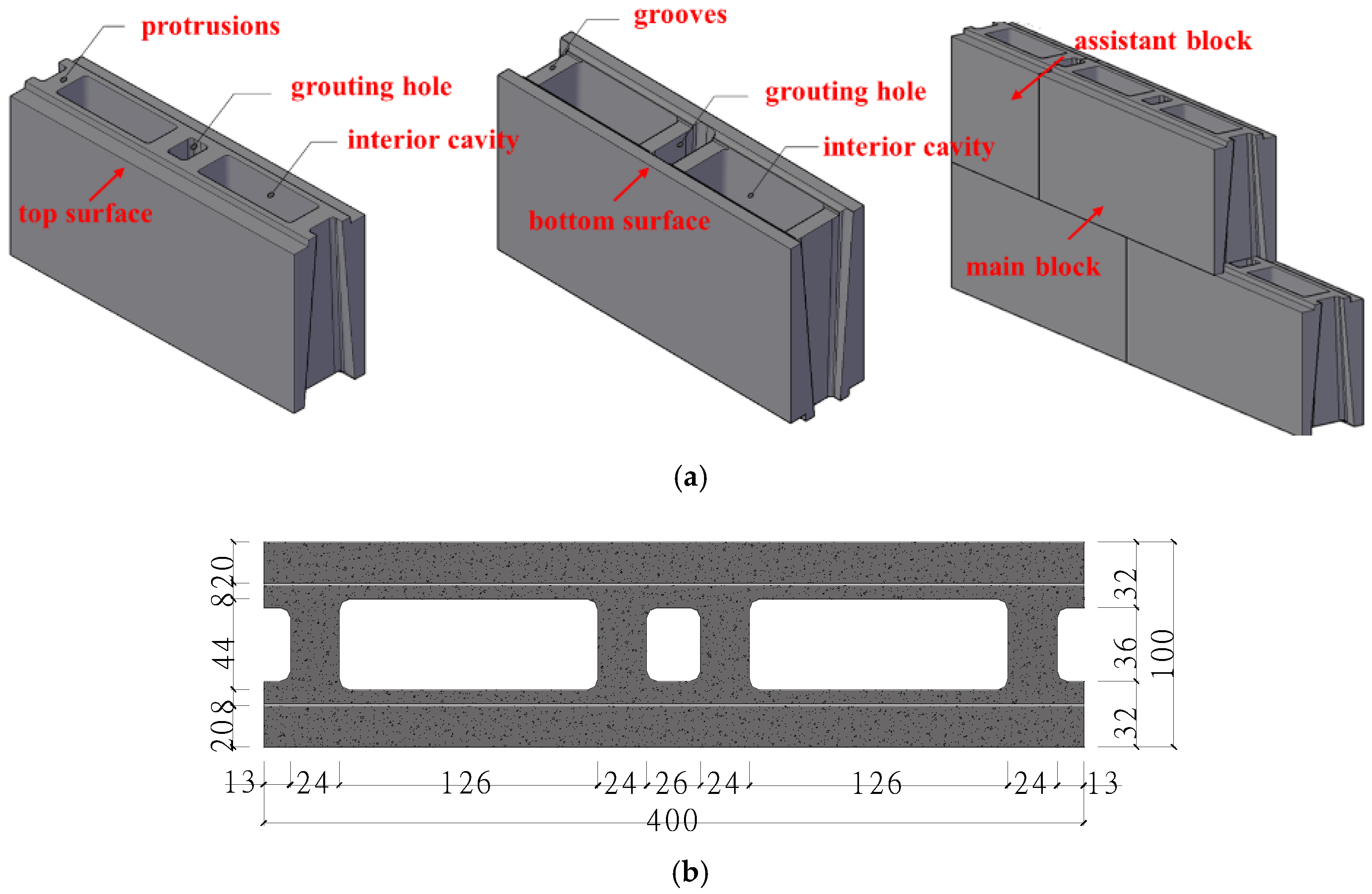
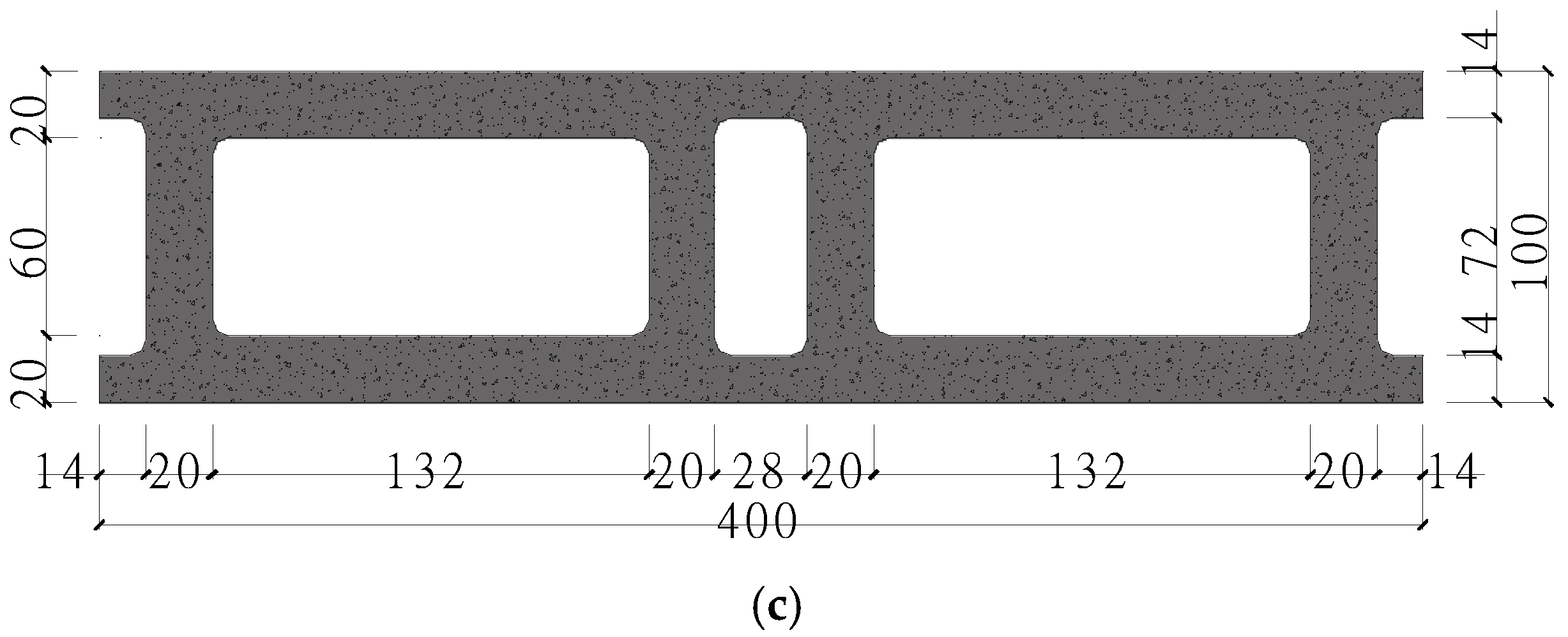
However, there are few studies reported on the use of recycled aggregate in interlocking hollow block for building construction, which is disappointing for the promotion and application of recycled concrete block masonry structures. Comprehensively considering the advantages of interlocking hollow blocks and the utilization of recycled aggregate, a new type of interlocking hollow block totally using recycled aggregate concrete (IHB-RAC) with compressive strength about 10 Mpa was proposed. Through the construction competition test of two middle-skilled workers to build the wall with the dimension of 1600 mm × 1600 mm (width × height) by using both the IHB-RAC block and the traditional concrete hollow block, the IHB-RAC block could help improving more than 56% of the construction efficiency (as the times used were about 11 min and 26 min respectively for the IHB-RAC masonry wall and the traditional hollow block ones). And, in order to avoid straight joint, the IHB-RAC was made into two different types of dimensions, called as main block and assistant block (as shown in Figure 1a). The specific dimensions of the main block are shown in Figure 1b,c, as the width is 400 mm, the thickness is 100 mm, the height is 200 mm. The width of the assistant block is half of the main block (200 mm), and the other dimensions are the same as the main block. On the whole, the shape of the hollow block is rectangular with a cavity rate of about 42%, and there are two big cavities inside, which could save the use of materials and make a positive contribution to the self-insulation and energy conservation of buildings. Between the two big cavities, there is also a small grouting hole inside, and the overall mechanical properties of the masonry using IHB-RAC could be further strengthened by pouring concrete inside the small holes. Above all, combining with the use of mortar, the protrusions and grooves on the top and bottom surfaces of the blocks acting as connecting keys could provide an effective connection while assembling them together into a wall. In order to promote the application of this new type block in building engineering, the compressive and shear properties of the masonries considering different mortar grades and the concrete used in the grouting holes were tested and studied.
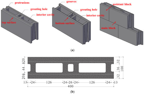
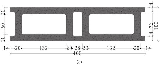
Figure 1.
Shape and dimensions (in mm) of the IHB-RAC. (a) Shape of the IHB-RAC; (b) Upper surface; (c) Bottom surface.
2. Material and Mixture Proportions of the IHB-RAC
The materials employed in the IHB-RAC were cement, stone powder, river sand and recycled aggregate. The cement used was composite Portland cement with a grade of 32.5 Mpa. The stone powder and recycled aggregates used were limestone powder and ordinary concrete recycled aggregates provided by Shihao Building Energy Saving Technology Company in Nanjing. The content of calcium carbonate in stone powder was 87.5%. The particle sizes of the stone powder were mainly between 6 and 80 μm tested by the laser particle size distribution instrument, and more than 50% were between 20 and 45 μm. The water absorption and fineness modulus of the river sand were 1.15% and 2.06 respectively. Table 1 and Table 2 presents the physical properties and the sieve rate (%) of the recycled aggregates according to standard GB/T14685-2011 [29].

Table 1.
Properties of the recycled aggregate.

Table 2.
Sieve rate of the recycled aggregate.
Based on the previous studies of the properties of recycled aggregate concrete [22,23,24,25,26,27], the specific mixing proportions of the RAC for the interlocking hollow blocks are shown in Table 3.

Table 3.
Mixing proportions of IHB-RAC.
3. Compressive and Shear Strength Test of the IHB-RAC Masonry
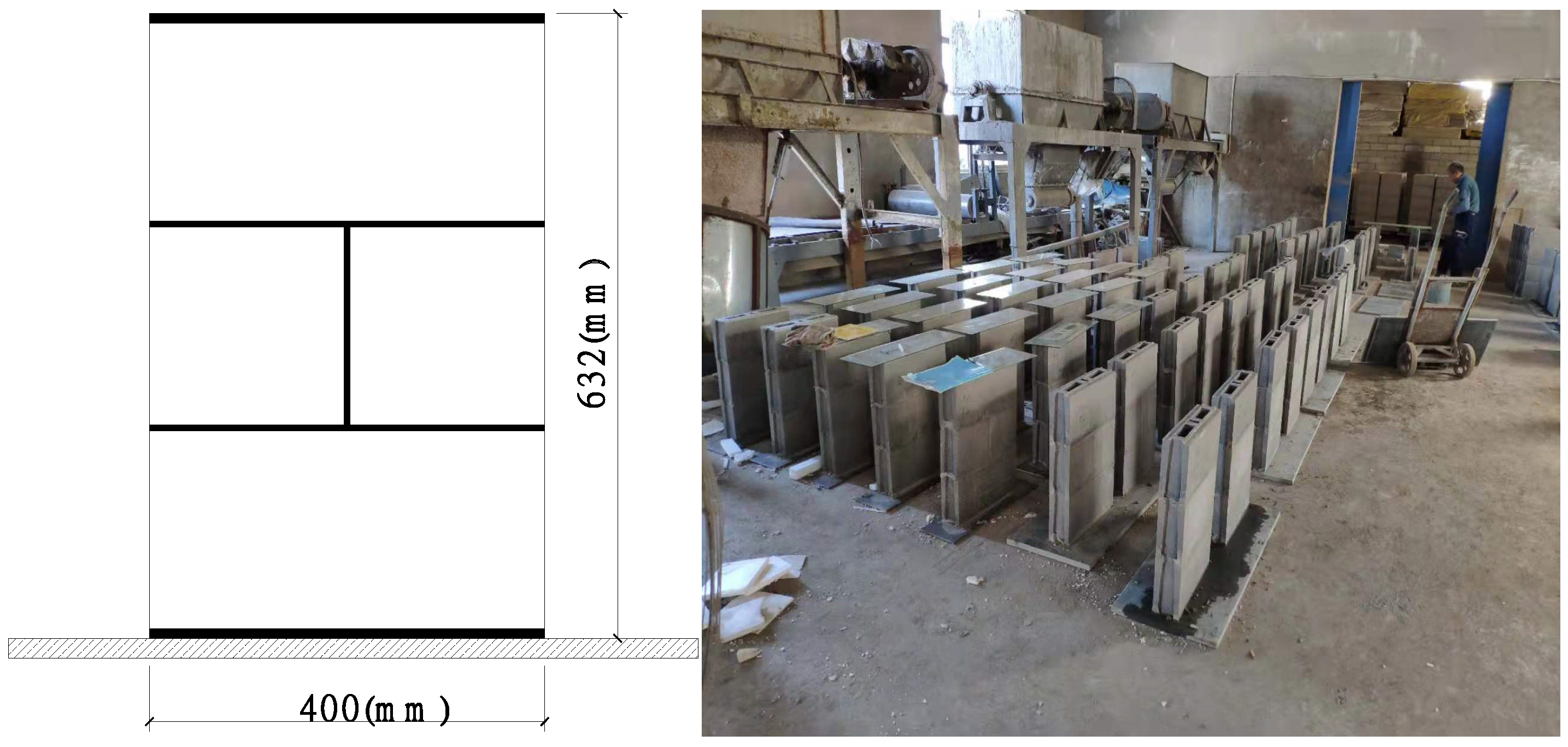
In order to study the axial load-bearing capacity and the shear strength of the masonry using IHB-RAC, 12 groups (5 specimens of each group for compressive strength test and 4 specimens of each group for shear strength test) of masonries considering different strength of mortar and the concrete used in the grouting holes were designed according to standard GB/T50129-2011 [30], and the thickness of the mortar used was 8 mm, as shown in Figure 2. Besides, in order to ensure a uniform load distribution on the specimens during the compression test, the rough upper and bottom surfaces of the masonries were made flat by using cement mortar with a thickness of 10 mm, and checked with a leveling instrument before the test. Among which, M7.5 grade mortar was used for groups A, B and C, and M15 grade mortar was used for groups D, E and F. In addition, the specimens of group A and D were designed without concrete cast into the grouting holes, as the grade of concrete used in the grouting holes for groups B, E and C, F were C30 and C40, respectively. The detailed characteristics of the specimens are shown in Table 4.
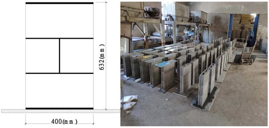
Figure 2.
Specimens design.

Table 4.
Characteristics of each group of IHB-RAC masonry specimens.
3.1. Material Properties
3.1.1. Compressive Strength of the IHB-RAC
The compressive strength of the IHB-RAC was tested by SYE-2000 hydraulic loading device. According to the test method introduced in standard GB/T4111-1997 [31], the mortar was used on the rough surfaces of the specimens and cured for more than 3 days to ensure a uniform distribution of the axial load before the test. The axial load was applied under load control procedure at a constant loading rate of 10~30 kN/s during the loading process. The strength of 5 main blocks and 5 assistant blocks were measured respectively and the test results are shown in Table 5. The mean values of the tested main blocks and assistant blocks were 10.2 Mpa and 10.4 Mpa respectively, which could be defined as MU10 grade block according to Chinese code GB/T8239-2014 [32].

Table 5.
Compressive strength of IHB-RAC.
3.1.2. Compressive Strength of Mortar and Concrete
The mixture proportions of the mortar used were determined according to Chinese standard JGJ/T98-2010 [33]. The compressive strength of the mortar was tested by 6 cubes (70.7 mm × 70.7 mm × 70.7 mm) for each group of mixture proportions after 28 days of curing, as the tested result is shown in Table 6. The mean values of the two types of mortar were 8.5 Mpa and 15.8 Mpa respectively calculated according to the method introduced in standard JGJ/T98-2010, and which could be defined as Mb7.5 and Mb15 grade mortar respectively.

Table 6.
Compressive strength of mortar.
The mixture proportions of the concrete used were determined according to Chinese standard JGJ/55-2011 [34]. The compressive strength of the concrete was tested by 3 cubes (150 mm × 150 mm × 150 mm) for each mixture proportions after 28 days of curing, as the tested result is shown in Table 7. The mean values of the two types of concrete were 32.8 Mpa and 40.2 Mpa respectively, which could be defined as C30 and C40 grade concrete respectively.

Table 7.
Compressive strength of concrete.
3.2. Test Setup and Loading Procedure
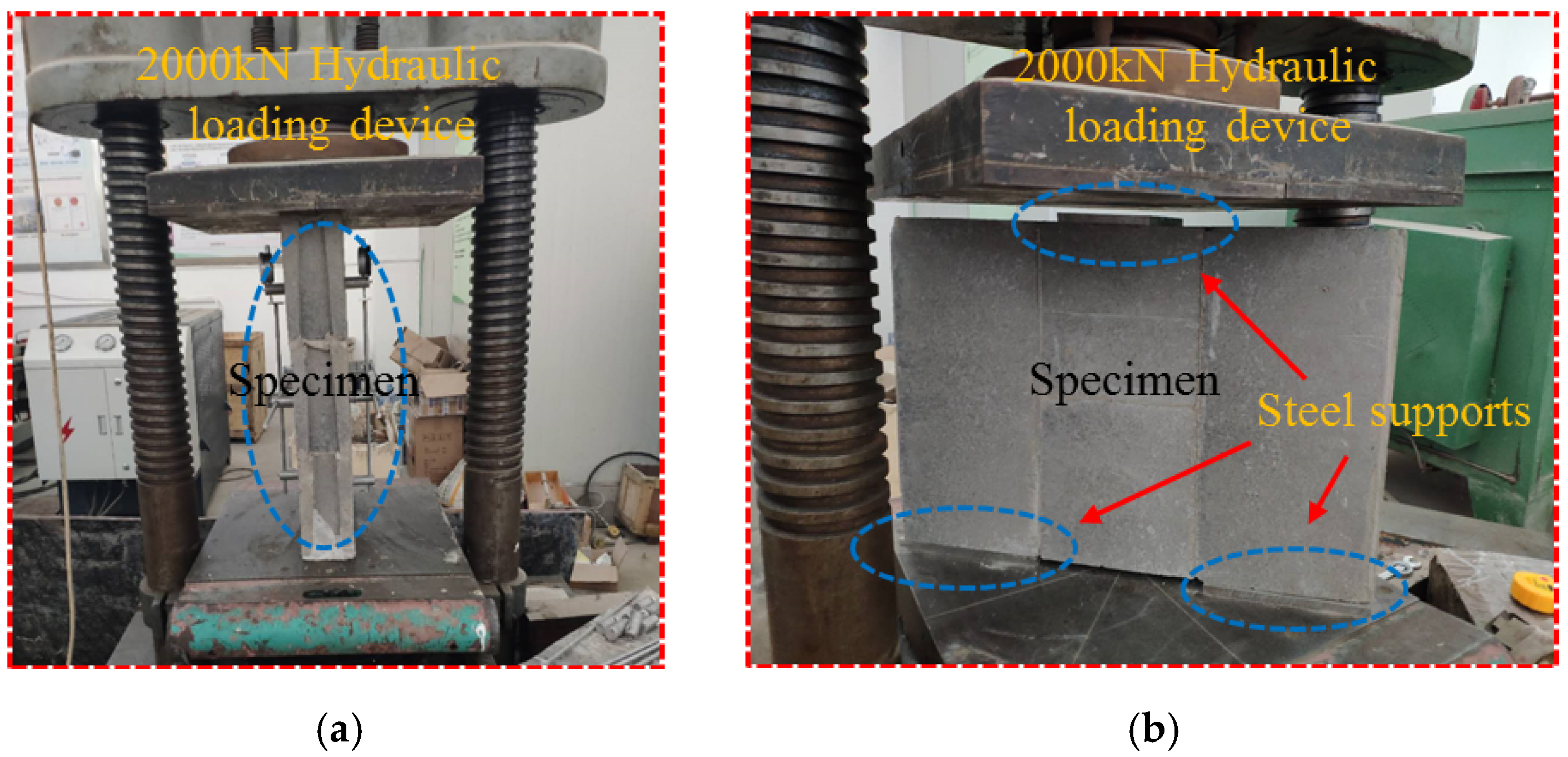
The axial compression strength and shear strength of the masonry was tested by the 2000kN hydraulic loading device, as shown in Figure 3. For the compression strength test, the specimen was fixed on the loading table vertically, as shown in Figure 3a. Referring to the relevant code GB/T50129-2011 [30], before the test, some quartz sand was used under the bottom surface of the specimens, and a pre-loading process was applied by using 10% of the load-bearing capacity of the specimen to eliminate the unwanted spaces in the device. The axial load was then unloaded to zero to start the formal loading process. During the formal loading process, 10 kN was used as a gradual loading increment and which was reduced to 5 kN when the specimens were approaching failure. For the shear strength test, the specimen was put on the loading table horizontally, as shown in Figure 3b. To ensure that the shear force was applied to the mortar joint of the masonry, three steel plates were used as supports on the top and the bottom surfaces of the specimen. During the test, the vertical load was applied continuously and slowly with a constant adjusted loading speed to ensure that the specimen could be destroyed within 1~3 min. When any one of the two horizontal joints failed, it was considered that the specimen failed and had lost its bearing capacity.
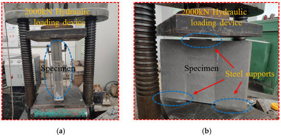
Figure 3.
Test setup. (a) Compression strength test; (b) Shear strength test.
3.3. Test Results and Observations
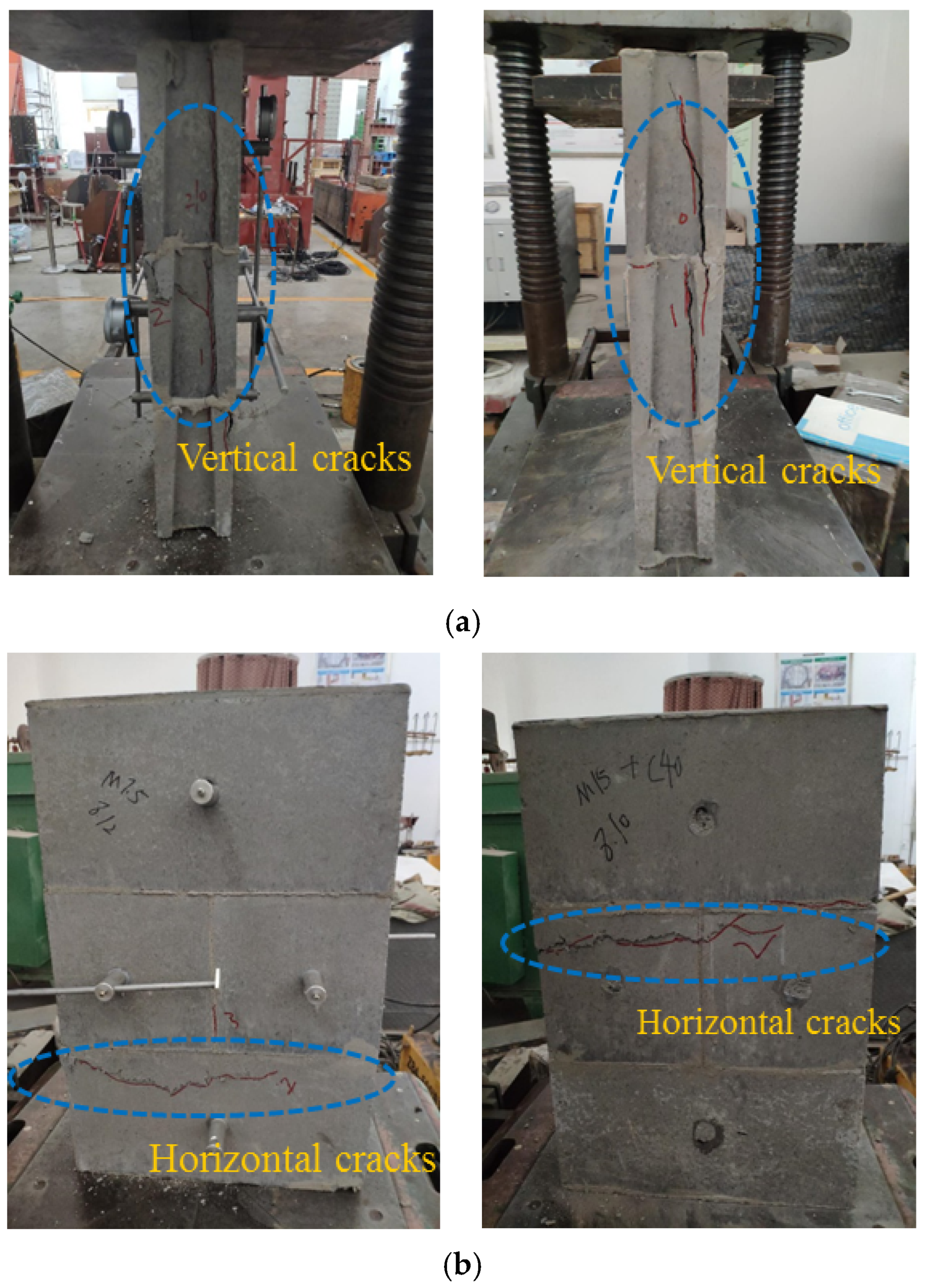
For the compressive strength test, the typical failure modes of each group of the test specimens are shown in Figure 4. When the load came into over 60% of the peak load (as the mean values were 75%, 63%, 68%, 60%, 60%, 63% respectively for group Ac, Bc, Cc, Dc, Ec, Fc), vertical crushing cracks firstly appeared on the upper positions of the narrow surfaces of the specimens. With the increase of the axial load, more vertical cracks appeared independently from the top to the bottom along the height of the specimens, and the length and width of them developed constantly. When the vertical load reached about 90% of the peak load, horizontal cracks began to appear on the wide sides of the specimen, and an obvious and continuous cracking sound could be heard at the same time. And then, with a loud crushing sound to be heard suddenly, the specimens failed totally while the vertical crushing cracks on the narrow surfaces connected together, and the horizontal crushing cracks developed through the whole cross-section of the specimens at the same time. Through comparison, the failure modes of all the specimens were very similar, which were characterized by the emergence and development of the vertical cracks on the narrow surfaces as well as the horizontal crushing occurring on the wide surfaces. There was no obvious difference in crack developing and failure mode between the specimens with or without concrete used in the grouting holes, mainly because the cross-section area of the grouting hole was small compared to the whole cross-section of the block, as the cross-section area ratio of the block was just 0.0369 for the main block. What’s more, no obvious crack or failure was found of the mortar joint throughout the whole loading process, indicating that the interlocking keys of the blocks could work well with the mortar and provide a reliable connecting function.
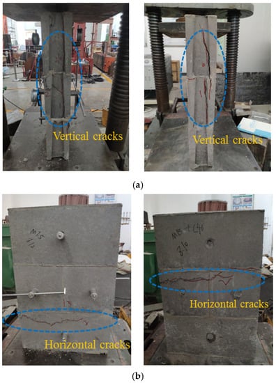
Figure 4.
Compression failure mode of specimens. (a) Narrow side; (b) Wide side.
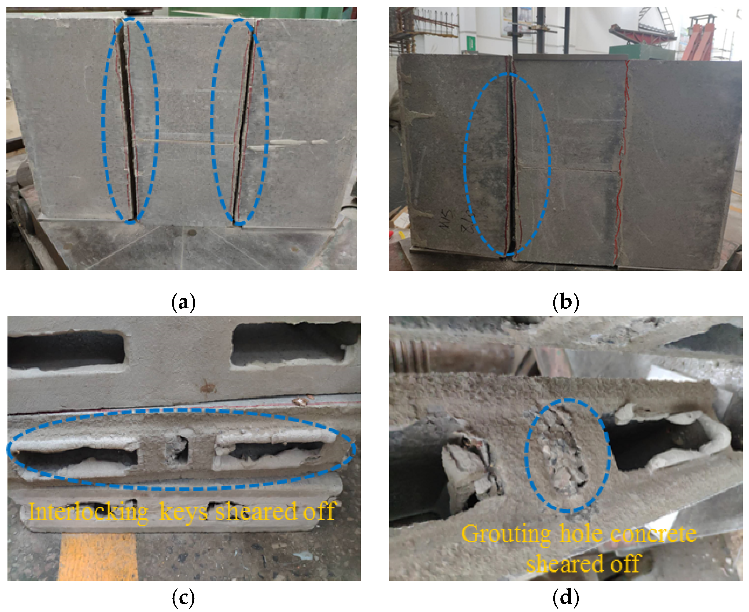
For the shear strength test, the typical failure modes of each group of the test specimens are shown in Figure 5. When the load came into over about 50% of the peak load (as the mean values were 48.3%, 51.7%, 52.5%, 50.8%, 53.4%, 55.1% respectively for group As, Bs, Cs, Ds, Es, Fs), shearing cracks could be observed on the mortar joints from the narrow sides of the specimens. With the shear force increasing, the horizontal mortar cracks developed continuously from both sides to the middle part of the masonries. Then, when the load came into over about 75% of the peak load (as the mean values were 75.8%, 77.4%, 81.2%, 76.1%, 82.3%, 84.6% respectively for group As, Bs, Cs, Ds, Es, Fs), the shearing cracks of the mortar joints developed throughout the whole cross-section of the masonries, and the mortar of the joints lost their shear strength after that. After that, the shear force began to be totally borne by the interlocking keys as well as the grouting hole concrete of the blocks, which was different from the traditional concrete hollow blocks, as the masonries using traditional hollow blocks almost lost their bearing capacity at this stage after the mortar joint completely cracked [14,15,16,17].
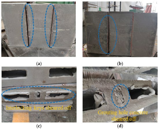
Figure 5.
Shear failure mode of specimens. (a) Double-surface shear failure; (b) Single-surface shear failure; (c) Shear cross-section (ungrouted); (d) Shear cross-section (grouted).
Through comparison, increasing the mortar grade and using grouting hole concrete had little effect on the failure mode of the specimens. In general, there are two main failure modes of the masonry, as double-surfaces shear failure (shown in Figure 5a) and single-surface shear failure (shown in Figure 5b), and the failure cross-sections are shown in Figure 5a,b. Most of the test specimens showed double-surfaces shear failure, indicating that the shear strength of the two mortar shear joints of the test masonry were almost equal. This was because that the interlocking keys of the block could provide an excellent connecting function, which could avoid the big differences between the mortar joint strength caused by the uncertainty of the construction level as well as the uneven distribution of joint mortar. Nevertheless, only a few of the test specimens using grouting hole showed single-surface failure, which could mainly be attributed to the uniform shear force applied to the joints by the loading device. However, it could be observed that the joint mortar of the unseparated shearing surfaces had already cracked throughout the whole cross-section; but the interlocking keys and the grouting hole concrete had not been sheared off totally, further indicating the excellent performance of the masonry.
3.4. Tested Compressive and Shear Strength of the IHB-RAC Masonry
For the compressive strength test, the peak load of the specimens is shown in Table 8. According to the calculation method specified in Chinese code GB/T50129-2011 [30], the corresponding compressive strength could be obtained. As shown in Equation (1), a reduction coefficient should be used in the formula to represent the influence of the stability when the ratio of height to thickness () is larger than 5 for the specimens:
where is the tested axial compressive strength of the masonry in units of Mpa; is the axial load of the specimens; is the area of cross-section of the specimens; and is the stability coefficient for the masonry under axial load, which could be determined according to Chinese code GB50003-2011 [18]. As the ratio of height to thickness () of the tested masonries was 6.952 (), the corresponding stability coefficient calculated was 0.93 for the masonry specimens.

Table 8.
Compressive strength of the IHB-RAC masonry.
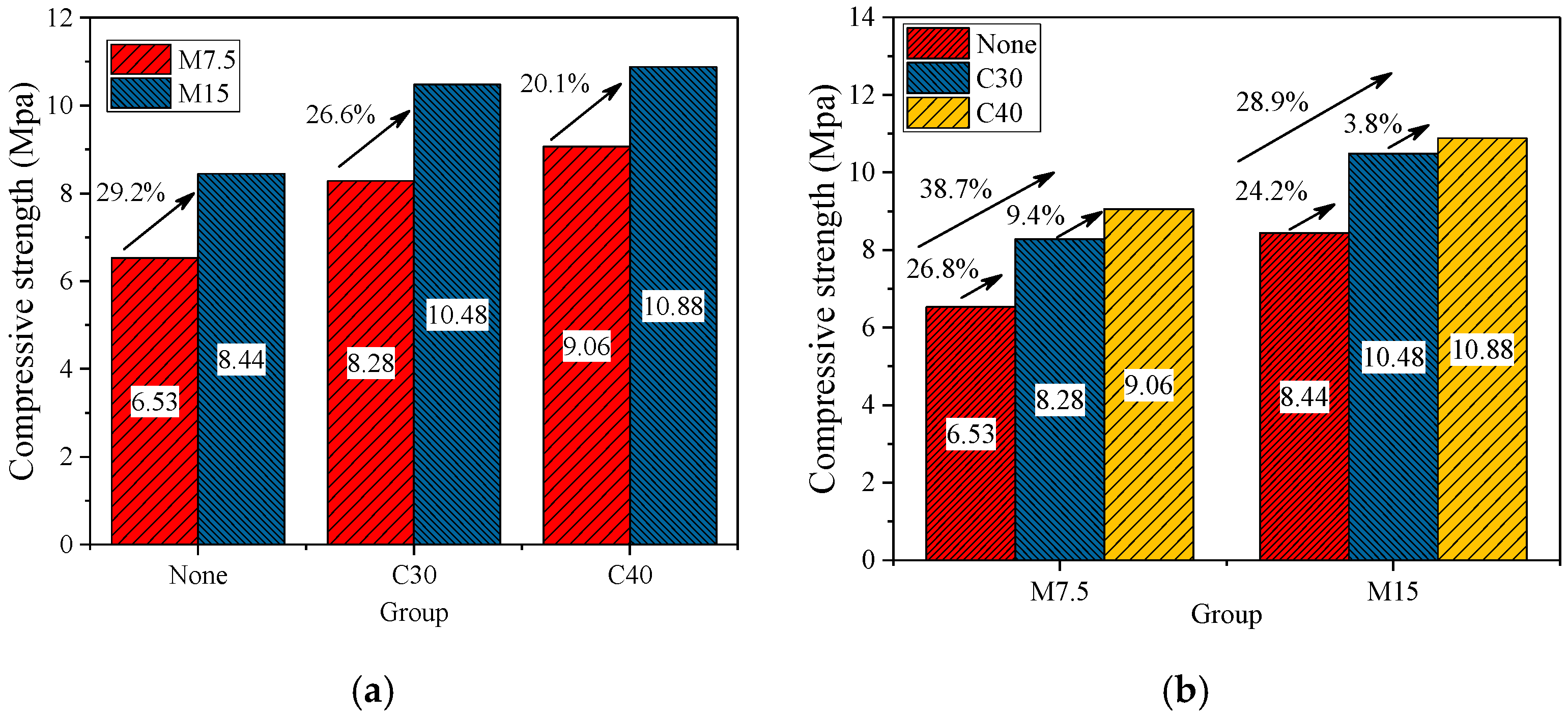
The mean values of the compressive strength of the tested specimens were shown in Figure 6, and the test results were compared from different perspectives. Through comparison, improving the strength grade of mortar had a positive effect on increasing the compressive strength of the IHB-RAC masonry. As shown in Figure 6a, the compressive strength of each group of the specimens were all increased by more than 20% while the Mb15 grade mortar was used compared to using Mb7.5 grade mortar. Furthermore, increasing the mortar grade had a most obvious improvement (increased by 29.2%) on the compressive strength of the ungrouted specimens. The influence of the concrete used in the grouting holes of the specimens was compared in Figure 6b. Through comparison, the concrete used could also increase the compressive strength of the specimens obviously. While the Mb7.5 grade mortar was used, the compressive strength of the specimens using C40 grade concrete in the grouting holes were increased by 38.7% compared to the ones without concrete used. While the Mb15 grade mortar was used, the corresponding strength was increased by 28.9%
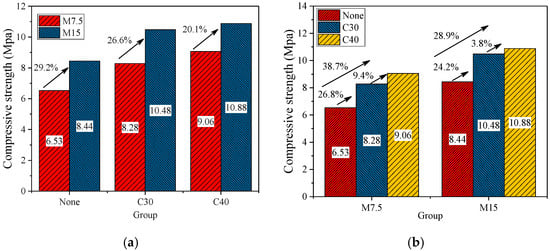
Figure 6.
Comparison of the compressive strength of specimens (mean value). (a) Comparison under different mortar strength; (b) Comparison under different strength of grouting hole concrete.
For the shear strength test, the peak load of the specimens tested were shown in Table 9. According to the calculation method specified in Chinese code GB/T50129-2011 [30], the corresponding shear strength of the specimens could be obtained by Equation (2),
where is the tested shear strength of the masonry in units of Mpa; is the horizontal shear force of the specimens; is the area of cross-section of the specimens.

Table 9.
Shear strength of the IHB-RAC masonry.
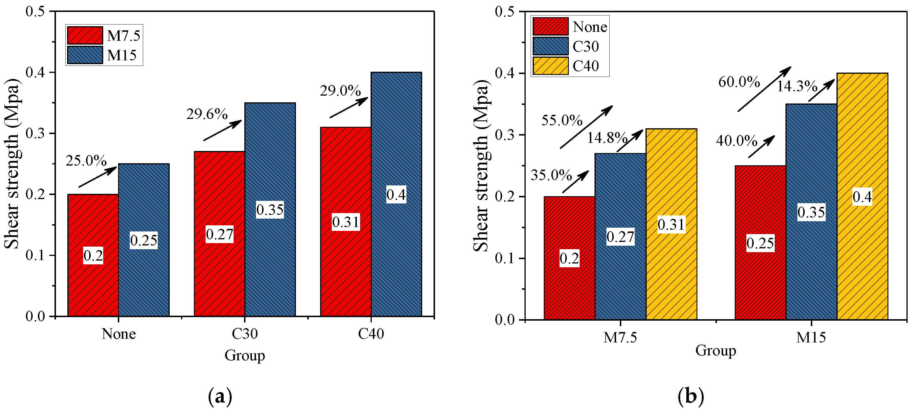
Through the comparison of the mean values of the tested specimen shear strength, both increasing the mortar strength and using grouting hole concrete could obviously increasing the shear strength of the IHB-RAC masonry too. As shown in Figure 7a, the shear strength of each group of the specimens were all increased by more than 25% while the Mb15 grade mortar was used compared to using Mb7.5 grade mortar. Furthermore, increasing the mortar grade had a most obvious improvement (increased by 29.6%) on the compressive strength of the specimens with C30 grade concrete used in the grouting holes. The influence of using grouting hole concrete on the shear strength was compared in Figure 7b. Through comparison, the shear strength of the specimens using C30 grouting hole concrete were increased by above 35% than the ones without using grouting hole concrete (as increased by 35.0% and 40.0% while using Mb7.5 and Mb15 grade mortar respectively), and the values were increased by above 55% while using C40 grouting concrete than the ones without using grouting concrete (as increased by 55.0% and 60.0% while using Mb7.5 and Mb15 grade mortar respectively). However, the effect of increasing the grouting concrete grade on improving the shear strength of the IHB-RAC masonry was not so high, as the values were increased by within 15% for the masonries using C40 concrete compared to C30.
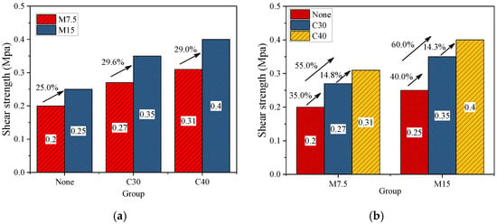
Figure 7.
Comparison of the shear strength of specimens (mean value). (a) Comparison under different mortar strength; (b) Comparison under different strength of grouting hole concrete.
3.5. Calculation of the Compressive and Shear Strength of the IHB-RAC Masonry
In order to better study the mechanical properties of the IHB-RAC masonry, the experimental results of the test specimens were compared with the calculated results obtained from Chinese code GB50003-2011 [18] to check the suitability of the standards, as shown in Table 10 and Table 11. In order to make an accurate prediction of the compressive strength of the masonry, modifying coefficients were used considering the positive contributions of the connecting keys. In addition, according to the test results, an appropriate calculation method for accurately predicting the shear strength of the grouted IHB-RAC masonry was proposed by separately considering the effort of the mortar and the grouting hole concrete.

Table 10.
Comparison between test compressive strength and calculation results (Mpa).

Table 11.
Comparison between test shear strength and calculation results (Mpa).
In code GB50003-2011, the calculation formula for predicting the mean value of the compressive strength of hollow block masonry was shown as Equation (3),
where is the mean value of the hollow block masonry compressive strength in units of Mpa (without concrete in the grouting holes); and are the mean value of the compressive strength of the block and mortar used respectively; and are the reduction coefficients related to the block type, taking as 0.46 and 0.9 for concrete hollow block respectively; and is the modifying coefficient related to the strength of the mortar used, taking as 1.0 here. Lastly, another modifying coefficient as () should be multiplied in the formula if the value of is larger than 10 Mpa.
The calculation formula for predicting the mean value of the axial compressive strength of masonry with concrete in the grouting holes is shown as Equation (4),
where is the mean value of the hollow block masonry compressive strength with concrete in the grouting holes; is the same as in Equation (3); is an enhancing coefficient considering the positive effect of the grouting hole concrete, taking as 0.63 here; is the cross-section area of the grouting holes, taking as the mean value of the grouting holes on the top and bottom surfaces of the specimens; is the area of the cross-section of the masonry specimen; and is the mean value of the compressive strength of the grouting hole concrete used.
According to the comparison in Table 10, the tested values of the compressive strength of the IHB-RAC masonry were higher than that of the code formula calculated results, indicating that the calculation formulas provided in code GB50003-2011 were relatively safer to be used to predict the axial load-bearing capacity of the masonry in structural designing. Among these, the difference between the test and calculated values for specimens without grouting hole concrete (group Ac, Dc) was relatively smaller, as within 15% overall. There was a big difference (above 20%) between the test and calculated values for the specimens with grouting hole concrete (group Bc, Cc, Ec, Fc). Among them, the biggest difference was group Cc, which was 29%.
In order to accurately predict the compressive strength of the masonry, the calculation method was modified based on the formulas in the code GB50003-2011. Considering the positive contributions of the connecting keys and the grouting hole concrete on the compressive strength of the masonry, based on the univariate linear-regression analysis of the tested and calculated results, an amplification coefficient as 1.1 was suggested to be multiplied to in Equation (3), as the modified value of was 0.51. Similarly, an amplification coefficient as 1.3 was multiplied to in Equation (4), as the modified value of was 0.82. By comparison, the difference between the calculated values of the modified formulas and the test values were within 4%.
In code GB50003-2011, the calculation formulas for both predicting the mean values of the shear strength of hollow block masonry with or without grouting hole concrete are shown in Equations (5) and (6) respectively:
where is the mean value of the hollow block masonry shear strength in units of Mpa (without concrete in the grouting holes); is the coefficient to represent the different types of block (as 0.069 for concrete block masonry). is the compressive strength of the mortar used. is the mean value of the hollow block masonry shear strength in units of Mpa (using concrete in the grouting holes); and is the compressive strength of the hollow block masonry with concrete in the grouting holes (using the same value as in Equation (4)).
According to the comparison in Table 11, Equation (5) could accurately predict the shear strength of the non-grouted IHB-RAC masonry, and the difference between the test and the code calculation values were within 4%. However, for masonries with grouting hole concrete, the code calculation results were much higher than the test results, as the test shear strength was only 25~35% of the calculated values. The main reason was that Equation (6) did not reasonably consider the influence of the concrete filling rate of the masonry, and the equation overestimated the contribution of the grouting hole concrete, as the concrete filling rate of the IHB-RAC block was only 0.036, which was relatively lower than traditional ones.
In order to reasonably consider the positive effect of the grouting hole concrete and make a precise prediction, previous studies [17,35,36] tried to separately consider the effort of the mortar and the grouting hole concrete by adding the contribution of the concrete core to Equation (5). Considering the complex interaction between the grouting concrete core and the block, the calculation method proposed by Gao Xiang [34] considering the filling rate of the concrete is shown as in Equation (6):
where is the cross-section area ratio of the grouting hole (0.0369 for the IHB-RAC block); is the coefficient associate with the block type, and the value of it was 0.46 determined by the univariate linear-regression analysis of the tested and calculated results of the IHB-RAC masonry.
From the comparison of the calculation results in Table 11, Equation (7) could accurately predict the shear strength of the IHB-RAC masonry while using grouting hole concrete, and the difference with the test values were within 7% on the whole.
4. Conclusions
Comprehensively considering the advantages of interlocking hollow blocks and the utilization of recycled aggregate, a new type of interlocking hollow block using recycled aggregate concrete (IHB-RAC) was proposed in this study, and the corresponding compressive and shear strength, as well as the failure mode of the masonries considering different strength of mortar and the concrete used in the grouting holes were studied by experiments. At last, the calculation methods of predicting the compressive and shear strength of the masonries were proposed for engineering application according to test results. The following conclusions could be drawn according to the experimental research and analysis:
- The mean values of the compressive strength of the tested main blocks and assistant blocks using recycled aggregate concrete were 10.2 Mpa and 10.4 Mpa respectively, which could be defined as MU10 grade block according to Chinese code GB/T8239-2014.
- For the compressive strength test, the failure modes of the masonries with different mortar and grouting hole concrete grades were similar, which was characterized by the emergence and development of the vertical cracks on the narrow surfaces as well as the horizontal crushing occurred on the wide surfaces. The interlocking keys of the blocks could work well with the mortar and provide a reliable connecting function as no obvious crack or failure was found of the mortar joint.
- For the shear strength test, there were two failure modes as single-surface shear failure and double-surfaces shear failure for all the test specimens, and most of the masonries showed double-surfaces shear failure attributed to the excellent connecting function of the interlocking keys, which could avoid the big differences between the mortar joint strength caused by the uncertainty of the construction level as well as the uneven distribution of joint mortar.
- Different from the traditional masonries losing their shear strength after the shearing mortar joint completely cracked, the connecting keys of the IHB-RAC blocks could go on undertaking the shear force after the mortar joint failed to work.
- The tested compressive strength of the IHB-RAC masonries were lower than the calculated values according to code GB50003-2011. Amplification coefficient as 1.1 and 1.3 were suggested respectively to the code formulas considering the contribution of the connecting keys, and the difference between the calculated values of the modified formulas and the test values were within 4%.
- The calculation method in code GB50003-2011 extremely overestimated the shear strength of the grouted IHB-RAC masonry. According to the test results, an appropriate calculation method for accurately predicting the shear strength of the grouted IHB-RAC masonry was proposed by separately considering the effort of the mortar and the grouting hole concrete, and the differences between test and calculated results were within 7%.
The present work is a preliminary experimental study on the mechanical properties of the IHB-RAC masonry. In order to comprehensively study the properties of the masonry, more experimental research studies are needed, and the replacement ratio of recycled aggregate (%), whether or not using steel bars in the grouting holes, as well as the influence of the axial compressive stress ratio on the shear strength, should be considered in the further studies.
Author Contributions
Conceptualization, Z.C. and J.L.; methodology, J.L.; validation, H.Z., J.L.; investigation, H.Z.; data curation, J.L.; writing—original draft preparation, J.L.; writing—review and editing, J.L. and W.C.; project administration, Z.C.; funding acquisition, Z.C. All authors have read and agreed to the published version of the manuscript.
Funding
This study was financially supported by the National Key R&D Program of China (No.2018YFD1100402), the Fundamental Research Funds for the Central Universities, and the Postgraduate Research & Practice Innovation Program of Jiangsu Province (No.KYCX17_0125). The viewpoints of this paper represent only the authors’ opinions and do not represent the sponsors’ views.
Data Availability Statement
Not applicable.
Conflicts of Interest
The authors declare that they have no known competing financial interests or personal relationships that could have appeared to influence the work reported in this paper.
References
- Li, J.; Chen, Z.; Chen, W.; Xu, Z. Seismic performance of pre-cast self-insulation shear walls made by a new type of foam concrete with high strength and low thermal conductivity. Structures 2020, 24, 124–136. [Google Scholar] [CrossRef]
- Li, J.; Chen, Z.; Chen, W. Axial load-bearing capacities of pre-cast self-insulation walls made by foam concrete. Structures 2020, 27, 1951–1961. [Google Scholar] [CrossRef]
- Yin, N.Z.; Zhang, X.G.; Song, F.S. Fired Brick-tile Technology; China Architecture and Building Press: Beijing, China, 1983. (In Chinese) [Google Scholar]
- Wu, J.; Bai, G.-L.; Wang, P.; Liu, Y. Mechanical properties of a new type of block made from shale and coal gangue. Constr. Build. Mater. 2018, 190, 796–804. [Google Scholar] [CrossRef]
- Ali, Y.A.; Fahmy, E.H.; AbouZeid, M.N.; Shaheen, Y.B.; Mooty, M.N.A. Use of expanded polystyrene wastes in developing hollow block masonry units. Constr. Build. Mater. 2020, 241, 118149. [Google Scholar] [CrossRef]
- Deng, M.; Zhang, W.; Li, N. In-plane cyclic loading tests of concrete hollow block masonry walls retrofitted with high ductile fiber-reinforced concrete. Constr. Build. Mater. 2020, 238, 117758. [Google Scholar] [CrossRef]
- Ramamurthy, K.; Sathish, V.; Ambalavanan, R. Compressive Strength Prediction of Hollow Concrete Block Masonry Prisms. Struct. J. 2000, 97, 61–67. [Google Scholar]
- Mohamad, G.; Lourenco, P.B.; Roman, H.R. Mechanics of hollow concrete block masonry prisms under compression: Re-view and prospects. Cem. Concr. Compos. 2007, 29, 181–192. [Google Scholar] [CrossRef]
- Sarhat, S.R.; Sherwood, E.G. The prediction of compressive strength of ungrouted hollow concrete block masonry. Constr. Build. Mater. 2014, 58, 111–121. [Google Scholar] [CrossRef]
- Liu, S.; Zhang, J.; Liu, L.; Guo, H.; Wang, B. Compressive performance of new types of load-bearing horizontal-hole interlocking concrete hollow blocks. Adv. Struct. Eng. 2019, 22, 1368–1383. [Google Scholar] [CrossRef]
- Ma, H.; Ma, Q.; Gaire, P. Development and mechanical evaluation of a new interlocking earth masonry block. Adv. Struct. Eng. 2020, 23, 234–247. [Google Scholar] [CrossRef]
- Ali, M.S.; Gultom, R.J.; Chouw, N. Capacity of innovative interlocking blocks under monotonic loading. Constr. Build. Mater. 2012, 37, 812–821. [Google Scholar] [CrossRef]
- Thanoon, W.A.; Jaafar, M.S.; Kadir, M.R.A.; Ali, A.A.A.; Trikha, D.N.; Najm, A.M. Development of an innovative interlocking load bearing hollow block system in Malaysia. Constr. Build. Mater. 2004, 18, 445–454. [Google Scholar] [CrossRef]
- Safiee, N.A.; Nasir, N.A.M.; Ashour, A.F.; Abu Bakar, N. Behaviour of interlocking mortarless hollow block walls under in-plane loading. Aust. J. Struct. Eng. 2018, 19, 87–95. [Google Scholar] [CrossRef]
- Yang, X.; Wu, H.; Zhang, J.; Wang, H. Shear Behavior of Hollow Concrete Block Masonry with Precast Concrete Anti-Shear Blocks. Adv. Mater. Sci. Eng. 2019, 2019, 1–10. [Google Scholar] [CrossRef]
- Yuan, Q.; Gao, W. Experimental study on basic mechanical properties of mortise and tenon joint type assem-bly-block masonry. J. Build. Struct. 2016, 440–447. (In Chinese) [Google Scholar] [CrossRef]
- Gao, W. Study on Basic Mechanical Properties of Mortise-Tenson Block Masonry. Master’s Thesis, Beijing Jiaotong University, Beijing, China, 2016. [Google Scholar]
- Chinese National Standard. Code for Design of Masonry Structures (GB50003-2011); China Architecture & Building Press: Beijing, China, 2012.
- Liu, C.; Fan, Z.; Chen, X.; Zhu, C.; Wang, H.; Bai, G. Experimental Study on Bond Behavior between Section Steel and RAC under Full Replacement Ratio. KSCE J. Civ. Eng. 2019, 23, 1159–1170. [Google Scholar] [CrossRef]
- Liang, C.; Ma, H.; Pan, Y.; Ma, Z.; Duan, Z.; He, Z. Chloride permeability and the caused steel corrosion in the concrete with carbonated recycled aggregate. Constr. Build. Mater. 2019, 218, 506–518. [Google Scholar] [CrossRef]
- Liu, C.; Lv, Z.; Zhu, C.; Bai, G.; Zhang, Y. Study on Calculation Method of Long Term Deformation of RAC Beam based on Creep Adjust-ment Coefficient. Ksce J. Civ. Eng. 2019, 23, 260–267. [Google Scholar] [CrossRef]
- Poon, C.S.; Kou, S.; Lam, L. Use of recycled aggregates in molded concrete bricks and blocks. Constr. Build. Mater. 2002, 16, 281–289. [Google Scholar] [CrossRef]
- Matar, P.; Dalati, R.E. Using recycled concrete aggregates in precast concrete hollow blocks. Mater. Werkst 2012, 43, 388–391. [Google Scholar] [CrossRef]
- Chen, Z.; Liu, W. Study on basic mechanical properties of recycled concrete block masonry. Earthq. Eng. Eng. Dyn. 2014, 1, 133–141. [Google Scholar]
- Abed, M.; Nemes, R. Mechanical Properties of Recycled Aggregate Self-Compacting High Strength Concrete Utilizing Waste Fly Ash, Cellular Concrete and Perlite Powders. Period. Polytech. Civ. Eng. 2019, 63, 266–277. [Google Scholar] [CrossRef]
- Zhuo, L.; Chen, B. Compression behavior of recycled aggregates concrete hollow block masonry. Build. Chin. Ceram. Soc. 2013, 10, 2155–2159. [Google Scholar]
- Zhuo, L.; Chen, B. Shear behavior of hollow block masonry with recycled aggregates concrete. Build. Chin. Ceram. Soc. 2013, 32, 2618–2621. [Google Scholar]
- Zhang, J. The compressive performance of recycled aggregates concrete hollow block masonry. Constr. Technol. 2014, 43, 109–111. [Google Scholar]
- Chinese National Standard. National Pebble and Crushed Stone Code for Buildings (GB/T14685-2011); China Standards Press: Beijing, China, 2011.
- Chinese National Standard. Standard for Test Method of Basic Mechanics Properties of Masonry (GB50129-2011); China Architecture & Building Press: Beijing, China, 2011.
- Chinese National Standard. Test Methods for the Small Concrete Hollow Block (GB/T4111-1997); China Standards Press: Beijing, China, 2011.
- Chinese National Standard. Normal Concrete Small Blocks (GB/T8239-2014); China Standards Press: Beijing, China, 2014.
- Chinese National Standard. Specification for Mix Proportion Design of Masonry Mortar (JGJ/T98-2010); China Architecture & Building Press: Beijing, China, 2010.
- Chinese National Standard. Specification for Mix Proportion Design of Ordinary Concrete (JGJ55-2011); China Architecture & Building Press: Beijing, China, 2011.
- Song, L. Experimental Study on Basic Mechanical Behavior and Non-Linear FEA of Concrete Block Masonry. Master’s Thesis, Hunan University, Changsha, China, 2005. [Google Scholar]
- Gao, X. Research on Mechanical Properties of Concrete Block Masonry and Seismic Behavior of Reinforced Masonry Mul-Tiwythe Wall. Master’s Thesis, Hunan University, Changsha, China, 2010. [Google Scholar]
Publisher’s Note: MDPI stays neutral with regard to jurisdictional claims in published maps and institutional affiliations. |
© 2021 by the authors. Licensee MDPI, Basel, Switzerland. This article is an open access article distributed under the terms and conditions of the Creative Commons Attribution (CC BY) license (http://creativecommons.org/licenses/by/4.0/).

