Article

Substitute Building Materials in Geogrid-Reinforced Soil Structures

Department for Water, Environment, Civil Engineering and Safety, University of Applied Sciences Magdeburg-Stendal, Breitscheidstraße 2, D-39114 Magdeburg, Germany
*
Author to whom correspondence should be addressed.
Sustainability 2021, 13(22), 12519; https://doi.org/10.3390/su132212519
Submission received: 9 September 2021 / Revised: 29 October 2021 / Accepted: 5 November 2021 / Published: 12 November 2021

Abstract

:
The feasibility of substitute building materials (SBMs) in engineering applications was investigated within the project. A geogrid-reinforced soil structure (GRSS) was built using SBM as the fill material as well as vegetated soil for facing and on top of the construction. Four different SBMs were used as fill material, namely blast furnace slag (BFS), electric furnace slag (EFS), track ballast (TB), and recycled concrete (RC). For the vegetated soil facing, a mixture of either recycled brick (RB) material or crushed lightweight concrete (LC) mixed with organic soil was used. The soil mechanical and chemical parameters for all materials were determined and assessed. In the next step, a GRSS was built as a pilot application consisting of three geogrid layers with a total height of 1.5 m and a slope angle of 60°. The results of the soil mechanical tests indicate that the used fill materials are similar or even better than primary materials, such as gravel. The results of the chemical tests show that some materials are qualified to be used in engineering constructions without or with minor restrictions. Other materials need a special sealing layer to prevent the material from leakage. The vegetation on the mixed SBM material grew successfully. Several ruderal and pioneer plants could be found even in the first year of the construction. The porous material (RB and LC) provide additional water storage capacity for plants especially during summer and/or heat periods. With regard to the results of the chemical analyses of the greening layers, they are usable under restricted conditions. Here special treatment is necessary. Finally, it can be stated that SBMs are feasible in GRSS, particularly as fill material but also as a mixture for the greenable soil.

1. Introduction

Mineral waste, and especially construction and demolition waste (CDW) as well as soil material, will be the largest waste stream in terms of volume once a certain level of urbanization has been reached. At the EU level, this state has already occurred, while at the global level, developing countries are still in the process of urbanization and a large material flow of CDW and soil materials will occur with a time lag. Nevertheless, this material flow represents both a global challenge and a significant resource potential for replacing mineral primary raw materials. In Germany, the material flow falls under the class of substitute building materials, i.e., “building materials from industrial manufacturing processes or from processing/treatment plants (waste, products) used instead of primary raw materials, such as recycled building materials (rubble), soil material, slags, ashes, railway ballast” [1]. In order to conserve natural raw material resources, substitute building materials should be preferentially used in construction projects in the future.
In Germany, around 350 million tons of waste are generated every year. Among other materials, the waste stream consists of about 250 million tons of mineral waste, such as 100 million tons of soil and stones, 73 million tons of CDW, 15 million tons of ashes and slags from energy plants, as well as 7 million tons of blast furnace slag, and 6 million tons of steel slag.
While the majority of CDW is reused [2], other materials are often used for low-value purposes, such as landfill cover materials or for backfilling of open-cast mines [3]. This kind of use is considered a downcycling process. Materials like slags, ashes, and CDW which are reused in the construction process are considered so-called substitute building materials (SBMs) in Germany. Therefore, the presented study will focus on upcycling applications, especially on the use of SBMs in green applications. Green applications refer to structures that will become vegetated. These applications are chosen because green elements will have a significant positive impact on lowering the local temperature and improving the living climate in cities. These green applications are called “Green Infrastructure” (GI), according to the European Commission (2013) [4]. Green infrastructure is “a strategically planned network of high quality natural and semi-natural areas with other environmental features, which is designed and managed to deliver a wide range of ecosystem services and protect biodiversity in both rural and urban settings”.
Widely used examples for GI in civil engineering are green roofs, vegetated gabions, or vegetated reinforced soil constructions. While these constructions are well established, the simultaneous use of SBMs in these constructions has rarely been carried out. Examples of used SBMs (waste silica) are described in Krawczyk et al. [5]. Molineux et al. [6] investigated the use of different recycled aggregates and combinations of them in green roof growing substrate. Carson et al. [7] used recycled and waste materials as substrates for roof greening. They described how to process aggregates from waste drywall, concrete, roof shingles, glass, and lumber cuttings which can be further used for roof substrates. Gagari et al. [8] provided a life-cycle assessment for the use of brick material with additional clay and compost ingredients. Several articles have described the experiences with recycled materials in geogrid-reinforced earth structures (GRSS), such as Santos et al. [9]. In this article, the authors reported the results of a 3.6 m high GRSS construction built with CDW material. Despite the construction being carried out on collapsible soil, the behavior of the wall was found to be satisfactory. Vieira et al. [10] described the performance of CDW as backfill in reinforced soil structures (RSS) and concluded that the resistance of the geogrid increases with the specimen size. Fleury et al. [11] investigated the influence of the drop and compaction of CDW material on the factor of built-in damage (RFID). They found out that grain size, drop height, and applied compaction method must be considered when calculating the factor of safety. Sachidanand and Divya [12] described the use of CDW material in RSS. The authors found that the geotechnical properties of the CDW met the requirements of an ideal backfill material for RSS. Ferreira et al. [13] reported on the results of time-dependent shear tests on CDW materials in connection with an underlying geotextile material. A stress relaxation was discovered in the tests. However, it was found that the peak and residual shear strength parameters in the long-time tests were similar to those in the benchmark tests. Viera [14] described the shear and pull-out behavior of different geosynthetic materials in connection with CDW material.
Most papers dealing with recycled materials in GRSS described the use of CDW. No applications of materials such as slag or track ballast to be used in RSS are published yet. This paper fills this gap as not only soil mechanics tests were carried out. In addition, the chemical constituents were analyzed and assessed with regard to potential hazards. Possible uses or additional necessary measures were derived. The present study describes the results of a pilot application in which a GRSS was constructed. For its construction, only SBM was used as fill materials and soil material for facing. Cost–benefit analyses as a comparison between conventional materials and SBM as well as life-cycle assessment were not within the scope of this work and will be subjects of future studies.

2. Materials and Methods

2.1. General Approach

This study consists of three parts. Firstly, additional soil mechanical tests were carried out. These tests complement the test results from preliminary tests. The results of these tests were reported in [15]. Additionally to the soil mechanical tests, greening tests were carried out to determine the best seed mixture for the facing material. Based on the results of these tests, a pilot application was erected.
The SBM materials used in the study are recycled brick material (RB), crushed lightweight concrete material (LC), blast furnace slag (BFS) electric furnace slag (EFS), track ballast (TB), and recycled concrete material (RC). The crushed brick material and lightweight concrete materials were used as greenable material for the GRSS facing. The remaining materials were tested for use as fill material in GRSS construction. Several geosynthetic materials, as well as steel grids, were also used.

2.2. Materials for Pilot Application

2.2.1. Fill Materials for Pilot Application

Four types of SBM were used as fill materials. The materials are shown in Figure 1.
The following properties and parameters were determined for the materials:
  • Soil type acc. to EN ISO 14688-1 [16] and EN ISO 14688-2 [17];
  • Density of soil particles (g/cm³);
  • Ignition loss (%);
  • Proctor density (g/cm³);
  • Shear resistance acc. to EN ISO 17892-10 [18];
  • Friction characteristics acc to EN ISO 12957-1 [19];
  • Field capacity (%);
  • pH value;
  • Chemical analyses.

2.2.2. Materials for Facing Elements of Pilot Application

The materials used in the pilot application for facing and greening purposes consist either of crushed brick material (RB) or crushed lightweight concrete (LC) which was mixed with organic soil with a mixture rate of two parts SBM and one part organic soil (Figure 2). The mixed materials were tested to determine soil mechanical and chemical properties and parameters. The following tests were carried out:
  • Soil type acc. to EN ISO 14688-1 [16] and EN ISO 14688-2 [17];
  • Density of soil particles (g/cm³);
  • Ignition loss (%);
  • Proctor density (g/cm³);
  • Field capacity (%);
  • pH value;
  • Chemical analyses.
For the initial greening tests, RB and LC were mixed with different materials. There was a total of 32 test samples. In each of the test pits, either RB material or LC was mixed with one or several components of compost, bark mulch, expanded clay, peat, and/or lava mulch. The used seed was a lawn mixture. Additional tests were carried out using a mixture of two parts RB or LC material and one part organic soil. In these tests, flower seed was used for greening. In total, 15 test samples were used in this pre-test. The organic soil was topsoil material from the site of the pilot application.

2.2.3. Additional Materials for Pilot Application and for Greening Tests

Several geosynthetics were used for the pilot application. The reinforcement of the GRSS was carried out using a laid uniaxial PET geogrid made of extruded monolithic flat bars which are factory-welded at the crossing points. The maximum tensile force of this material is 80 kN/m at a strain of less than 7%.
At the surface, a geosynthetic erosion mat was placed. At the bottom of the pilot construction and between the different chambers a geosynthetic seal layer was placed. The facing was stabilized with galvanized steel grid with a mesh wide of 5 cm in each direction. For the prior greening tests, additional materials like compost, bark mulch, expanded clay, peat, and lava mulch were used. The used seed was a lawn mixture in both tests.

2.3. Pilot Application

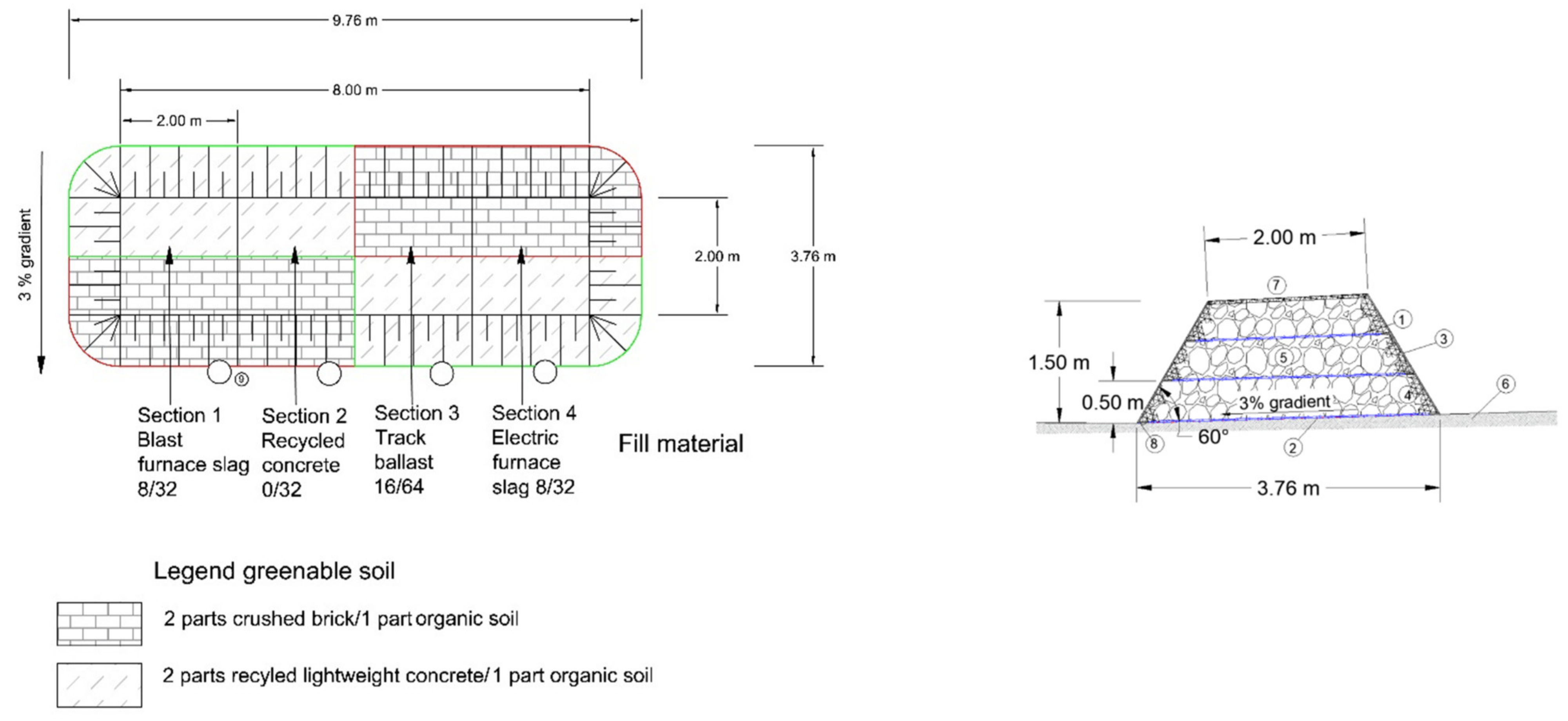
The layout of the pilot application can be seen in Figure 3.
The construction is divided into four parts. On each part, the fill material was foreseen according to the findings in Section 2.2. The construction height was 1.5 m, the slope angle was 60° (Figure 4).
At the ground of the steep slope construction, a horizontal sealing layer with a slight slope to the north side of the construction was placed. The leachate from the rainfall was sampled and transported in gutters and stored in shafts. The four sections are divided by vertical panels to make sure the leachate cannot be mixed between the sections. The leachate was analyzed several times during the lifespan of the construction. The aim was to identify potential differences in the water quality between the leachate and the results of the chemical analyses carried out on recycled materials.
The geogrid layers were placed with a 50 cm vertical difference. A PET material was used as geogrid reinforcement. This material is usable in alkaline environmental conditions. Additional tests were carried out to determine the reduction factor for installation damage (RFID/A2 acc. to [20]). Beneath the grid elements, an erosion protection mat and greenable soil were placed. The greenable soil was only slightly compacted. The facing was carried out using galvanized steel grid elements.
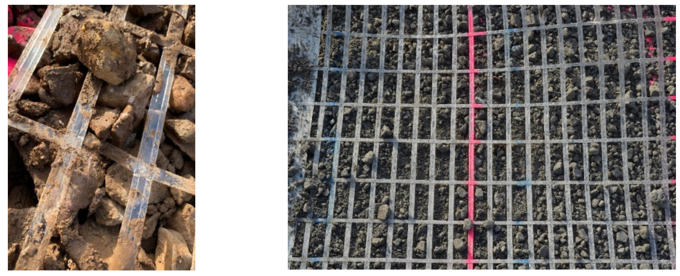
The RFID tests were carried out according to EBGEO [20] beside the pilot application. The geogrid was placed on a 15 cm base layer made from the 4 used SBM fill materials. The layout can be seen in Figure 5. Above the geogrid layer additional 15 cm of SBM was placed. The SBM materials were compacted using a vibrating plate with a mass of 135 kg and a performance of 3.1 kW (4.1 HP). The vibration plate was the same used for compaction in the pilot application. After compacting the top layer, the material was removed and geogrid samples were taken for tensile tests according to EN ISO 10319 [21].
After the installation, the construction was covered with greenery. A seed mixture consisting of grass seeds and flowers seeds was used for this purpose.

3. Results

3.1. Soil Mechanical and Chemical Test Results

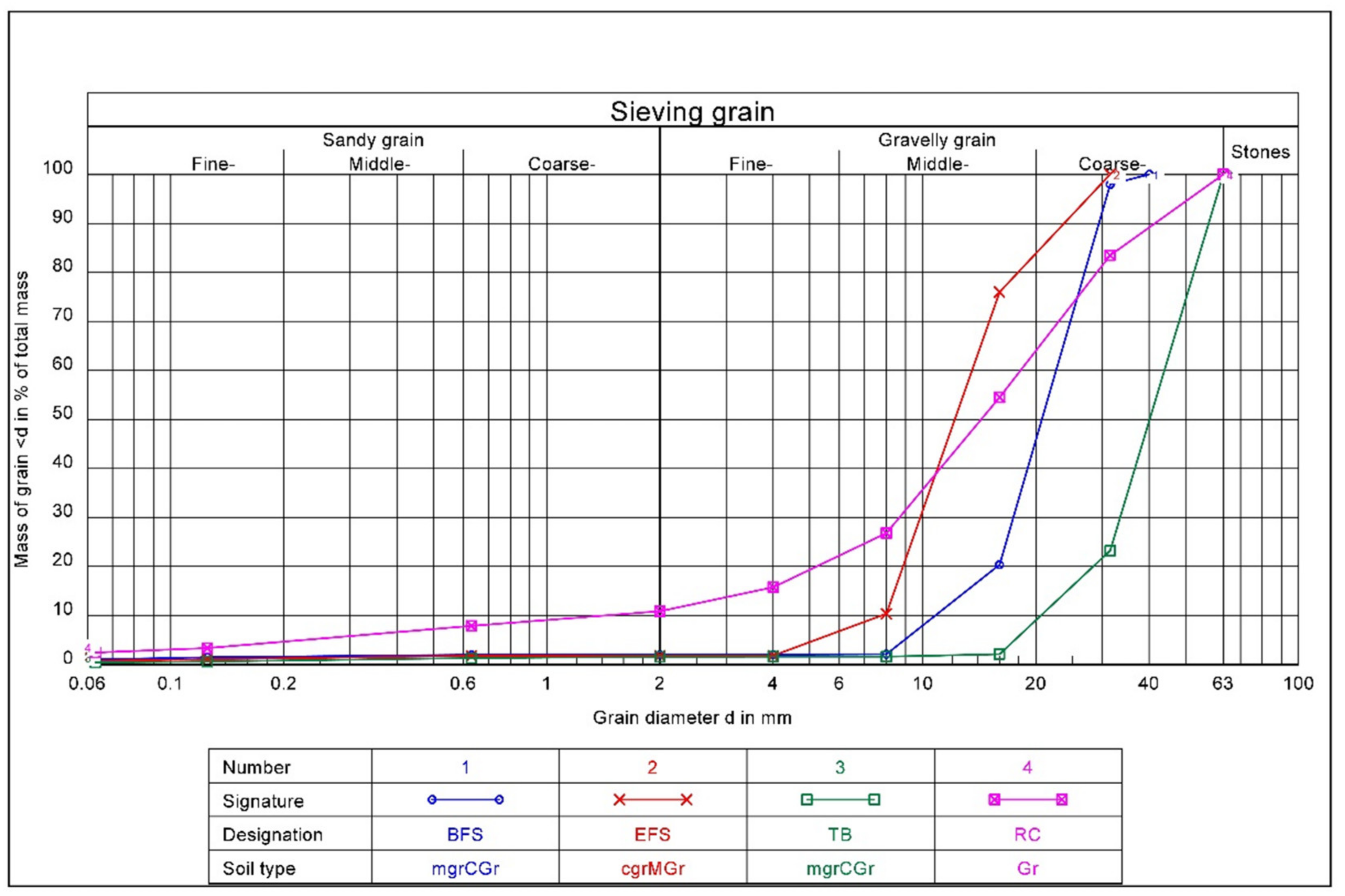
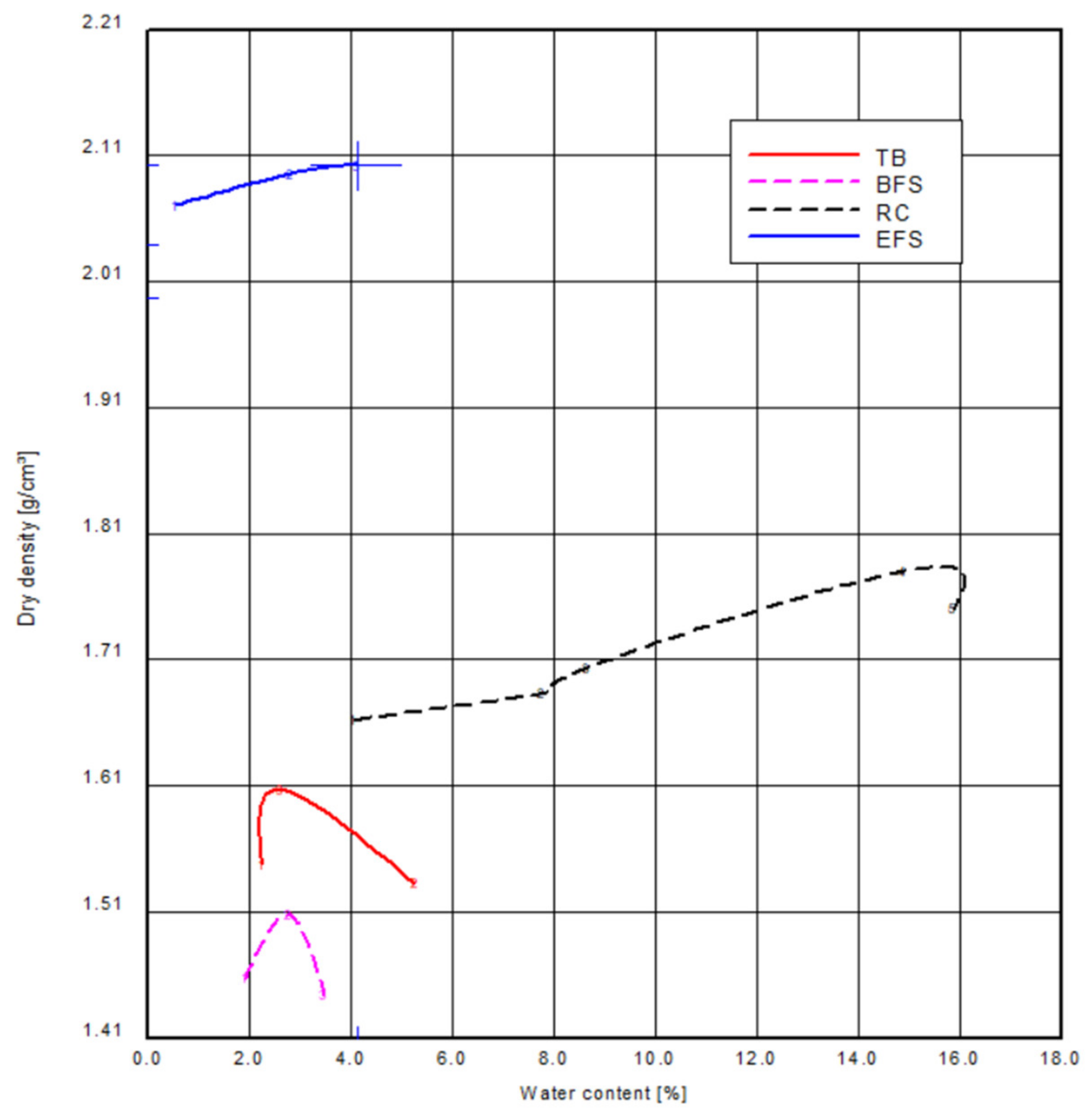
The soil mechanical and chemical test results for the GRSS materials are summarized in Table 1 and Table 2 as well as in Figure 6 and Figure 7.
The results show that the soil mechanical parameters of the tested SBM are without exception within the range of comparable gravel. Differences are only noticeable for some Proctor densities or grain densities. The maximum dry density that a material can reach is called Proctor density. The achieved Proctor density values are shown in Figure 8. This is due to the source materials.
For the shear tests, a large shear box with dimensions of length × width × height of 50 × 50 × 20 cm was used. Each test consisted of three sub-tests with normal stresses of 25, 50, and 100 kPa. The tests were carried out both exclusively on the soil material used in the construction and additionally with a geogrid layer in the joint between the upper and lower shear box. The results of the shear tests can be seen in Figure 9. The shear tests show that the materials can be used without restriction for KBE constructions in terms of soil mechanics.
The field capacity refers to the field the maximum water content that an unsaturated soil can retain against gravity under undisturbed soil conditions, according to ISO 11074 [25].
With regard to the chemical investigations, it can be stated that the sulfate contents were high in nearly all materials (with exception of track ballast and EOS) and mostly resulted in a classification in recovery class Z2 according to LAGA M20 [24]. This also resulted in comparatively high specific electrical conductivities (leachate mineralization). Since sulfate contents are generally not critical, the following evaluation was carried out neglecting the sulfate values. The RC material has an allocation class of Z1.2 according to LAGA M 20. Exceeded benchmark values concern polycyclic aromatic hydrocarbons (PAH) according to EPA, the specific electrical conductivity, and sulfate. RB has an allocation class of Z1.2 because the values exceeded the benchmarks for PAH according to EPA, electrical conductivity, chloride, and sulfate. Blast furnace slag (BFS) has an allocation class of Z0 (neglecting the sulfate value, being Z2). Electric furnace slag (EFS) has an allocation class of Z0. Track ballast (TB) is to be assigned to allocation class Z0. Lightweight concrete (LC) is to be assigned to allocation class Z2, having exceeded benchmark values for lead and sulfate.
With regard to general feasibility, it can be concluded that the materials with a classification value Z2 can only be installed using a water-impermeable top layer or using additional technical safety measures. In such a case, Code of Practice M TS E [26] is authoritative. If sulfate is not considered critical, the materials are to be allocated to allocation classes Z 0 or Z 1.1. This means that the use of the materials is feasible in the following kinds of applications [24]:
-
Roads, paths, traffic areas (superstructure and substructure);
-
Industrial, commercial, and storage areas (superstructure and substructure);
-
Substructures of buildings;
-
Below the rootable soil layer of earthworks (noise and protection walls);
-
Substructures of sports facilities.
The SBM investigation results for the usable field capacity and air capacity show that water can be stored in RB/topsoil and LC/topsoil mixtures, but not in other materials. The air capacity values can be considered average due to the large pore space. The use of blast furnace slag, electric furnace slag, and recycled concrete as a greening layer is not recommended. Field and air capacity are affected by the capillarity of the material in relation to the fine particle content. Coarse structures are suspicious of washing and producing leachate. The components RB/topsoil and LC/topsoil mixtures are suitable for this purpose. In summary, it can be stated that the tested SBMs, if necessary with the use of technical safety measures, are also suitable in chemical terms for the use in plastic-reinforced earth constructions. The leachate pH value was measured to be alkaline, which means not usable for use in all geosynthetic GRSS constructions.
The greening material was only slightly compacted in the pilot application. For this reason, the pore content of the material could not be determined in a meaningful way. The organic content provides nutrient input for plants. The porosity of the RB and LC material provides additional water storage capacity. The pH value is also alkaline, which has some implications for the usability of the materials in GRSS (geogrid, erosion mat) as well as for the selection of revegetation materials. The chemical results show an expected outcome at high sulfate levels. The other ingredients except sulfate are within the benchmark ranges.

3.2. Preliminary Greening Test Results

In the greening tests carried out before the erection of the pilot application, the best results could be found with material mixtures supplemented with expanded clay and lava mulch. Other mixtures were also successful to different degrees. Even on pure brick or lightweight concrete material, some plants could be found. In the second part with either RB or LC mixed with organic soil the most of the greening tests were successful. Finally, the decision was made to use the ladder mixture for the pilot application. With a focus on further applications, this mixture will provide the most cost-effective solution.

3.3. Pilot Application

During the erection of the pilot application, the compaction grade of the different fill materials was determined. The values are within a range of 97 to 98%.
In the RFID tests (A2 value acc. to EBGEO) the results in Table 3 could be achieved:
It can be concluded that the damages on the geogrid are only minor. This finding can be confirmed by the results of the visual inspection (see next figures). No damage to the material was found in the tests with BFS, EFS, and RC. Only in the tests with TB were minor damages found as can be seen in Figure 10.
In terms of vegetation analysis, each GRSS side was investigated separately. The sowing was carried out in April 2020. On the east side, some germination could be seen already at the end of April, but mainly on the RB side. From May to June was observed that the RB/soil side was more densely vegetated than the LC/soil side. On the other hand, more vegetation appeared on the RB/soil side at the end of September and in mid-October. The trend shows that the RB/soil is suitable for rapid vegetation and LC/soil has more of a long-term positive effect.
At the south side of the GRSS, the findings from the east side were confirmed. In addition to the lush greening, however, it can also be seen that most of the plants have been dried out by the end of September. The reason is the higher sunlight exposure on the south side. In autumn (October to December), further greening was observed on the south side, with particular grass seed sprouting. No distinction can be made between the greening results of the RB/soil and LC/soil material mixtures. On the west side, the same setting like on the east and south sides is evident. The rapid vegetation of May and June is clearly visible on the RB/soil mixture (right) and only partially on the LC/soil mixtures (left). On the other hand, the vegetation withers faster on the RB/soil mixture than on the LC/soil mixtures. The north side is by far the best-vegetated slope. Initially, it is again recognizable that greening and blossoms can be seen earlier on the RB/soil mixtures (left) than on the LC/soil mixtures. In contrast to the other slopes, the shaded locations did not cause dry out or wither in summer, so that the slope has the highest degree of greening at the end.
The differences between the building materials can be assessed as follows,
-
RB material is coarser-grained compared to LC. As a result, it has a higher pore volume, which supports water flow and air capacity. The large pore spaces also give roots better opportunities to grow. The brick acts as a drainage layer. The RB’s disadvantage is that it has no real storage capacity due to high water permeability. A long-lasting, stable moisture level can therefore not be expected;
-
LC, on the other hand, is very fine-pored, and this property gives it a high storage capacity. With many small cavities, the water has plenty of room to spread and to be stored. Due to its good heat capacity, this SBM can store heat well when the outside temperature is too low and can insulate against heat when it is very hot. This offers the advantage that plants can thrive even on colder days/months and survive better in hot conditions. The disadvantage of the fine pores is that there is no good water permeability. When water enters LC, it runs off on the surface because the pores are too fine to allow the water to penetrate quickly. This characteristic does not guarantee fast plant growth. Furthermore, the pores block possible space for rapid root development. They, therefore, need more time to break through.
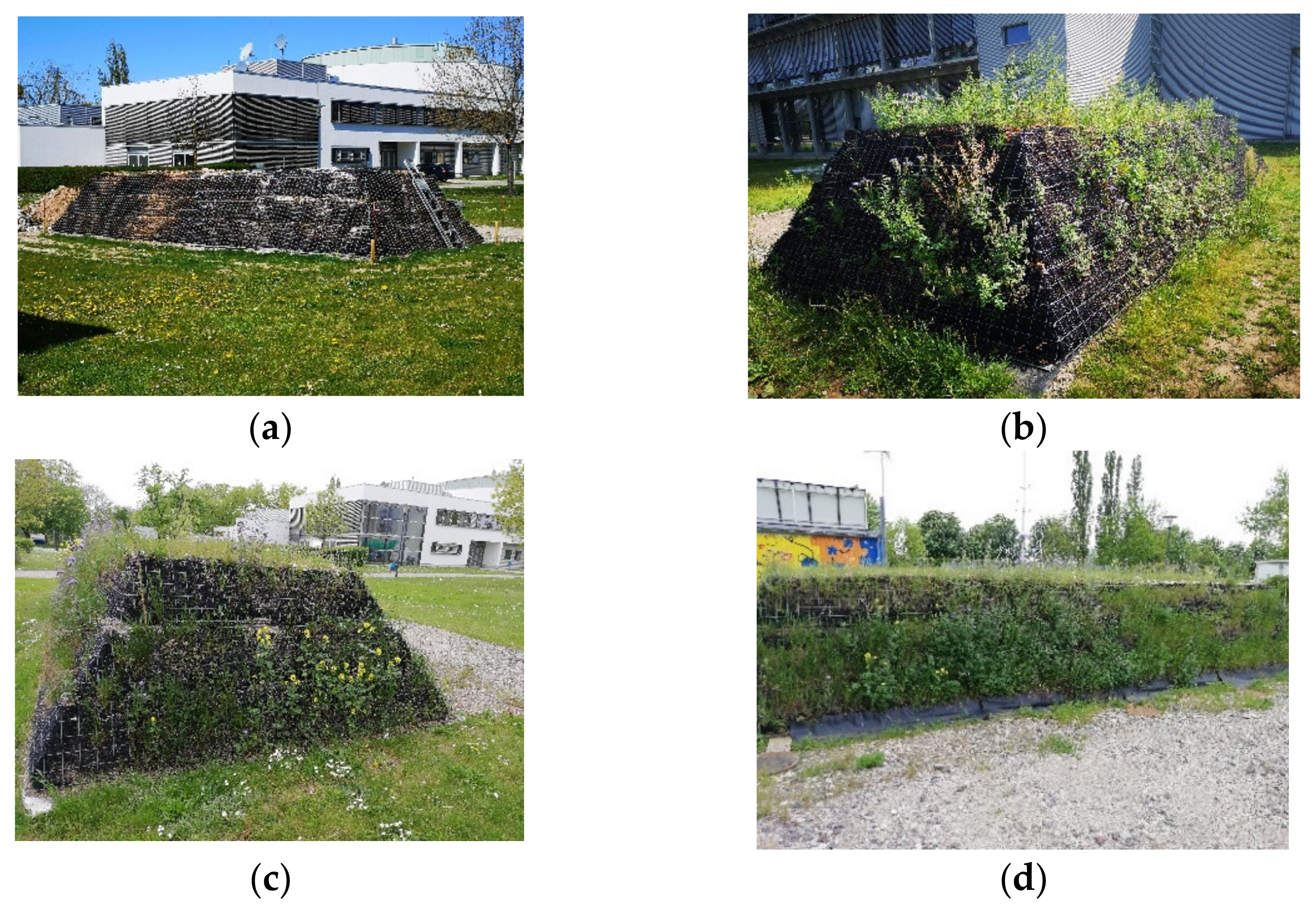
Looking at the GRSS as an overall structure, it can be seen that vegetation progressed in May, peaked in June (vegetation period 1), flowered from July to September, and re-flowered again in October (vegetation period 2). Figure 11 shows pictures of the pilot application at different points in time. Not only did the different SBMs have an influence on plant growth, but weather conditions did as well. The temperature rose since March. The peak was observed in August with an average of 21.9 °C. Since flowering took place in the period from June to September, the temperatures were possibly too high for the first vegetation. Comparing the precipitation total with the previous year, the year 2020 was drier. Only in June, August, and September was a higher precipitation level observed. However, it must be taken into account that the construction was irrigated. This took place especially in the very dry spring months and, to a lesser extent, in summer. A closer look at the precipitation patterns shows that there were no continuous rain phases. The final amount came mainly from short heavy rainfall events. In this situation, the soil cannot absorb the water fast enough. The rainwater runs off aboveground or into the sewage system. With normal precipitation events, the greening of the reinforced earth might have been maintained for a longer period (midsummer).
When looking at the flowering plants, all have low soil quality requirements and are very undemanding. Among others, the followings plants were found at the GRSS: White Mustard, Common Sheep weed, Field Bindweed, White Goosefoot, Field Thistle, Jacob’s Grasswort, and Mallow. These plants are considered pioneer or ruderal plants. Pioneer plants have a special adaptability for colonizing new, still vegetation-free habitats. These species occur more frequently in newly created habitats than in existing ecosystems. The two main characteristics for pioneer plants are,
-
Effective long-distance dispersal mechanism: Pioneer habitats emerge unpredictably and in isolation. Therefore, species with high seed numbers and with dispersal by wind (anemochory) and animal (ornithochory) are typical pioneers;
-
High hardiness: Tolerate extreme environmental conditions, established vegetation stands reduces occurring maxima e.g., in terms of temperature and soil water; furthermore, the soils usually show nutrient deficiencies or imbalances.
In addition to pioneer plants, there are also ruderal plants. These species prefer to settle on rubble and debris sites, stony slopes, disturbed roadsides, and similar territories. All the above criteria apply to the GRSS.

4. Conclusions

From a soil mechanics point of view, the proof was provided that SBM can be used in GRSS. This can be considered proof of the feasibility of SBM in GRSS and other engineering structures, such as gabion walls, green roofs, bridge abutments, as well as the construction of noise barrier dams or for backfilling structures. Further investigations are required in this regard. The soil mechanical parameters Proctor density, grain distribution, grain bulk density, and shear strength (friction angle) are comparable to those of primary building materials.
When considering the chemical properties, differentiation is necessary as well as an adaptation to the detailed conditions. The investigated materials are all suitable for recycling or reuse respectively, although the recycling feasibility differs depending on material type. The current legal situation also permits the recovery of Z2 materials in some areas. The technical prerequisites to prevent precipitation from penetrating the construction are given. For example, the use of plastic sealing membranes is a suitable measure. For the greening layer, other solutions must be sought here. While the RB material only has to fulfill minor additional requirements, in terms of LC, an additional treatment step must be interposed in order to immobilize potentially environmentally harmful constituents that cause classification in recycling class Z2. For obvious reasons, a cover as in the case of fill soils is ruled out. However, the effort to undertake such developments is justified, as crushed LC has proven to be an ideal material for greening layers, at least in combination with an organic admixture/soil material, respectively.
The results of the greening tests have shown that RB/soil and LC/soil mixtures are well suited for revegetation. First colonizers and ruderal plants can grow and spread very well. The different SBM properties are reflected in the vegetation. RB is well suited for quick vegetation success and LC, on the other hand, offers good conditions for long-term revegetation. The results support the conclusion of the feasibility of SBM-based GRSS as green infrastructure. In this way, the project results contribute to the closure of SBM loops for climate adaptation purposes.
Further tests must prove the durability and resistance to deterioration e.g., by freezing over a longer period of time. For this purpose, the pilot application will continue to be monitored regularly. The results will be reported in due course.

Author Contributions

Conceptualization, S.S. and P.S.; methodology, S.S., D.M. and P.S.; validation, S.S. and P.S.; formal analysis, D.M.; investigation, D.M., M.W. and T.H.; resources, D.M.; data curation, D.M.; writing—original draft preparation, S.S.; writing—review and editing, S.S. and P.S.; visualization, S.S. and D.M.; supervision, S.S. and P.S.; project administration, S.S.; funding acquisition, S.S. and P.S. All authors have read and agreed to the published version of the manuscript.

Funding

This research was funded by the Ministry of Environment, Agriculture and Energy Saxony-Anhalt, Germany, grant number FKZ U02/2019. Parts of the APC were funded by Naue GmbH & Co. KG, Espelkamp.

Institutional Review Board Statement

Not applicable.

Informed Consent Statement

Not applicable.

Data Availability Statement

The data presented in this study are available upon request from the corresponding author. The data are not publicly available due to privacy reasons.

Acknowledgments

The authors wish to thank the Ministry of Environment, Agriculture and Energy Saxony-Anhalt, Germany for funding the project, Naue GmbH & Co. KG, Espelkamp Germany for providing the used geogrid and funding parts of APC, and Salzgitter Flachstahl GmbH, Salzgitter, E. Friedrich GmbH, Salzgitter and Storck Umweltdienste GmbH, Magdeburg for providing the used SBM, respectively.

Conflicts of Interest

The authors declare no conflict of interest. The funders had no role in the design of the study; in the collection, analyses, or interpretation of data; in the writing of the manuscript, or in the decision to publish the results.

Abbreviations

BFSBlast furnace slag
CDWConstruction and demolition waste
cmdCross machine direction (secondary direction of geosynthetics reinforcement)
EFSElectric furnace slag
EPAEnvironmental Protection Agency
GRSSGeogrid-reinforced soil structure
LC(crushed) Lightweight concrete material
mdMachine direction (main direction of geosynthetics reinforcement)
PAHPolycyclic aromatic hydrocarbons
PETPolyethylenterephthalat
RBRecycled brick material
RCRecycled concrete material
RFIDReduction factor of installation damage
RSSReinforced soil structure
SBMSubstitute building material
TBTrack ballast

References

  1. Bundesministerium für Umwelt, Entwurf der Mantelverordnung. Available online: https://www.bmu.de/fileadmin/Daten_BMU/Download_PDF/Gesetze/mantelv_text.pdf (accessed on 3 October 2019).
  2. Kreislaufwirtschaft Bau. Kreislaufwirtschaft-Bau.de. Available online: http://kreislaufwirtschaft-bau.de/#aktuelleDaten (accessed on 30 October 2019).
  3. Ministerium für Umwelt, Landwirtschaft und Energie, Sachsen-Anhalts. Leitfaden zur Wiederverwendung und Verwertung von Mineralischen Abfällen in Sachsen-Anhalt; Ministerium für Umwelt, Landwirtschaft und Energie, Sachsen-Anhalts: Magdeburg, Germany, 2018.
  4. European Comission. Communication from the Commission to the European Parliament, the Council, the European Economic and Social Committee and the Committee of the Regions-Green Infrastructure (GI)—Enhancing Europe’s Natural Capital. 2013. Available online: https://eur-lex.europa.eu/resource.html?uri=cellar:d41348f2-01d5-4abe-b817-4c73e6f1b2df.0014.03/DOC_1&format=PDF (accessed on 3 October 2019).
  5. Krawczyk, A.; Domagała-Świątkiewicz, I.; Lis-Krzyścin, A.; Daraż, M. Waste Silica as a Valuable Component of Extensive Green-Roof Substrates. Pol. J. Environ. Stud. 2017, 26, 643–653. [Google Scholar] [CrossRef]
  6. Molineux, C.; Gange, A.C.; Connop, S.P.; Newport, D. Using recycled aggregates in green roof substrates for plant diversity. Ecol. Eng. 2015, 82, 596–604. [Google Scholar] [CrossRef]
  7. Carson, T.; Hakimdavar, R.; Sjoblom, K.; Culligan, P. Viability of Recycled and Waste Materials as Green Roof Substrates. In Proceedings of the GeoCongress 2012, Oakland, CA, USA, 25–29 March 2012. [Google Scholar] [CrossRef]
  8. Gargari, C.; Bibbiani, C.; Fantozzi, F.; Campiotti, C.A. Environmental Impact of Green Roofing: The Contribute of a Green Roof to the Sustainable use of Natural Resources in a Life Cycle Approach. Agric. Agric. Sci. Procedia 2016, 8, 646–656. [Google Scholar] [CrossRef]
  9. Santos, E.; Palmeira, E.; Bathurst, R. Performance of two geosynthetic reinforced walls with recycled construction waste backfill and constructed on collapsible ground. Geosynth. Int. 2014, 21, 256–269. [Google Scholar] [CrossRef]
  10. Vieira, C.S.; Pereira, P.; Ferreira, F.; Lopes, M.D.L. Pullout behaviour of Geogrids embedded in a recycled construction and demolition material. Effects of specimen size and displacement rate. Sustanability 2020, 12, 3825. [Google Scholar] [CrossRef]
  11. Fleury, M.P.; Santos, E.C.G.; Da Silva, J.L.; Palmeira, E.M. Geogrid installation damage caused by recycled construction and demolition waste. Geosynth. Int. 2019, 26, 641–656. [Google Scholar] [CrossRef]
  12. Vibha, S.; Divya, P.V. Geosynthetic-Reinforced Soil Wall with Sustainable Backfills. Indian Geotech. J. 2020, 51, 1–10. [Google Scholar] [CrossRef]
  13. Ferreira, F.; Pereira, P.; Vieira, C.; Lopes, M. Time-Dependent Response of a Recycled C&D Material-Geotextile Interface under Direct Shear Mode. Materials 2021, 14, 3070. [Google Scholar] [CrossRef] [PubMed]
  14. Vieira, C.S. Valorization of Fine-Grain Construction and Demolition (C&D) Waste in Geosynthetic Reinforced Structures. Waste Biomass-Valoriz. 2018, 11, 1615–1626. [Google Scholar] [CrossRef]
  15. Schneider, P.; Schwerdt, S.; Schulz, K.; Fiebig, S.; Mirschel, D. Feasibility of substitute building materials for circular use in urban green infrastructure. Civ. Eng. Des. 2020, 2, 159–168. [Google Scholar] [CrossRef]
  16. EN ISO 14688-1: Geotechnical Investigation and Testing-Identification and Classification of Soil-Part 1: Identification and Description (ISO 14688-1:2017), German version EN ISO 14688-1:2018; Beuth-Verlag: Berlin, Germany, 2018.
  17. EN ISO 14688-2: Geotechnical Investigation and Testing-Identification and Classification of Soil-Part 2: Principles for a Classification (ISO 14688-2:2017), German version EN ISO 14688-2:2018; Beuth-Verlag: Berlin, Germany, 2018.
  18. EN ISO 17892-10: Geotechnical Investigation and Testing-Laboratory Testing of Soil-Part 10: Direct Shear Test (ISO 17892-10:2018); German Version EN ISO 17892-10:2018; Beuth-Verlag: Berlin, Germany, 2019.
  19. EN ISO 12957-1: Geosynthetics-Determination of Friction Characteristics-Part1: Direct Shear Test (ISO/DIS 12957-1: 2018); German and English Version prEN ISO 12957-1:2018; Beuth-Verlag: Berlin, Germany, 2018.
  20. DGGT. EBGEO Empfehlungen für Planung und Bemessung von Bewehrungen mit Geokunststoffen; Deutsche Gesellschaft für Geotechnik, Ed.; Verlag W. Ernst und Sohn: Berlin, Germany, 2010; ISBN 978-3-433-02950-3. [Google Scholar]
  21. EN ISO 10319-Geotextiles-Wide-Width Tensile Test (ISO 10319: 1993); German Version EN ISO 10319:1996; Beuth-Verlag: Berlin, Germany, 1996.
  22. Schwerdt, S.; Schneider, P.; Mirschel, D. Abschlussbericht Forschungsprojekt Verbesserung und Stärkung der Urbanen Grünen Infrastruktur durch Einsatz von Ersatzbaustoffen in Kunststoff-Bewehrte-Erde-Konstruktionen (Recycle-KBE); Final Report; Magdeburg-Stendal University of Applied Sciences: Magdeburg, Germany, 2020. [Google Scholar]
  23. Hildebrandt, T.; Wilke, M. Verwendbarkeit von Recyclingbaustoffen als Ersatz zu Primärbaustoffen in Kunststioff-Bewehrte-Erde-Konstruktionen. Master’s Thesis, Magdeburg-Stendal University of Applied Sciences, Magdeburg, Germany, 2020, unpublished. [Google Scholar]
  24. Länderarbeitsgemeinschaft Abfall-LAGA. Mitteilungen der Länderarbeitsgemeinschaft (LAGA) 20 Anforderungen an die stoffliche Verwertung von mineralischen Reststoffen/Abfällen-Technische Regeln. Available online: https://www.laga-online.de/documents/m20_nov2003u1997_2_1517834540.pdf (accessed on 3 October 2019).
  25. Schulz, K. Untersuchung zu Einsatzmöglichkeiten von Ersatzbaustoffen in Bewehrter Erde als Grüne Infrastruktur. Bachelor’s Thesis, Magdeburg-Stendal University of Applied Sciences, Magdeburg, Germany, 2019, unpublished. [Google Scholar]
  26. M TS E. Merkblatt über Bauweisen für Technische Sicherungsmaßnahmen beim Einsatz von Böden und Baustoffen mit umweltrelevanten Inhaltsstoffen im Erdbau; FGSV Verlag: Köln, Germany, 2017; ISBN 978-3-86446-203-0. Available online: https://www.fgsv-verlag.de/pub/media/pdf/559.i.pdf (accessed on 30 October 2019).
Figure 1. Tested SBM as fill material from left to right: recycled concrete (RC), track ballast (TB), blast furnace slag (BFS), electric furnace slag (EFS). Source: Schneider.
Sustainability 13 12519 g001
Figure 2. SBM mixed with organic soil, left: before installation, right: after installation in a pilot application. Pictures: Schneider.
Sustainability 13 12519 g002
Figure 3. Top view and crosssection of the GRSS with recycled materials. Legend: 1—geogrid; 2—horizontal sealing; 3—facing (steel grid and erosion protection mat); 4—facing material/greenable soil; 5—fill material; 6—underground; 7—greenable soil; 8—drainage pipe; 9—collection shaft for leachate. Facing material 1:2 parts RB+1 part soil; facing material 2:2 part LC+1 part soil; Drawing: Schwerdt, Mirschel.
Sustainability 13 12519 g003
Figure 4. Left: View at the base layer of the pilot application before installation; Right: Northwest view at the greened construction in October 2020 (6 months after erection). Pictures: Schneider.
Sustainability 13 12519 g004
Figure 5. RFID tests: (a) base layer; (b) geogrid layer with test samples; (c) top layer; (d) vibrating plate.
Sustainability 13 12519 g005
Figure 6. Grain size distribution of fill material.
Sustainability 13 12519 g006
Figure 7. Grain size distribution of greening soil material.
Sustainability 13 12519 g007
Figure 8. Proctor density of the soil materials.
Sustainability 13 12519 g008
Figure 9. Results of shear tests: (a) recycled concrete (RC); (b) blast furnace slag (BFS); (c) electric furnace slag (EFS); (d) track ballast (TB).
Sustainability 13 12519 g009aSustainability 13 12519 g009b
Figure 10. Visual inspection of geogrid after RFID test: left: test with TB; some smaller damages can be seen; right: no damages in tests with BFS, EFS, and RC.
Sustainability 13 12519 g010
Figure 11. Pictures from the pilot application: (a) 1 month after installation view from the southeast; (b) 3 months after installation view from the southwest; (c) 1 year after installation view from the east; (d) 3 months after installation view from north.
Sustainability 13 12519 g011
Table 1. Results of soil mechanical and chemical tests of the fill materials [22,23].
BFSEFSRCTB
Soil classification
(EN ISO 14688-1)
mgrCGrcgrMGrGrmgrCGr
Soil classification
(EN ISO 14688-2)
Uniformly graded gravelUniformly graded gravelMedium to well-graded gravelUniformly graded gravel
Density of soil particles (g/cm³)2.41–2.833.84–3.962.55–2.572.66
Ignition loss (%)0000
Water absorption (%)24.525.8n.d.n.d.
Proctor density (g/cm³)1.51–1.582.10–2.161.781.61
pH value10.210.79.39.3
Field capacity (%)2.291.819.97n.d.
Air capacity (%)7.906.209.53n.d.
Shear parameter (soil) (φ’/c’) (°/kN/m²)54.3/053.6/053.2/059.6/0
Friction ratio (–)0.910.940.810.75
Chemical classification according to LAGA M20 * [24]Z2 (sulfate)Z0Z1.2 (sulfate)Z0
* Legend Chemical classification LAGA M 20: Z0—usable without restrictions; Z1.2—usable with minor restrictions above groundwater level; Z2—usable with restrictions (sealing layer).
Table 2. Results of soil mechanical and chemical tests of facing soil materials [22,23].
LC + SoilRB + Soil
Soil classification
(EN ISO 14688-1)
grcsiSacsisaGr
Soil classification
(EN ISO 14688-2)
Well-graded sandWell-graded gravel
Density of soil particles (g/cm³)1.892.47–2.64
Proctor density (g/cm³)1.241.96
Ignition loss (%)7.042.5
Field capacity (%)14.9613.96
Air capacity (%)2.135.55
pH value8.88.0
Chemical classification according to LAGA M20 * [24]Z2 (sulfate)Z1.2 (sulfate)
* Legend Chemical classification LAGA M 20: Z1.2—usable with minor restrictions above groundwater level; Z2—usable with restrictions (sealing layer).
Table 3. A2 values.
Table 3. A2 values.
SBMA2–Value (md) (–)A2–Value (cmd) (–)
EFS1.011.03
BFS1.001.00
RC1.011.00
TB1.081.06
Publisher’s Note: MDPI stays neutral with regard to jurisdictional claims in published maps and institutional affiliations.