Article

Optimal Sizing and Assessment of a Renewable Rich Standalone Hybrid Microgrid Considering Conventional Dispatch Methodologies

1
Department of Electrical, Electronic and Communication Engineering, Pabna University of Science and Technology, Pabna 6600, Bangladesh
2
Department of Electrical and Electronic Engineering, Rajshahi University of Engineering & Technology, Rajshahi 6204, Bangladesh
3
Department of Electrical Engineering and Industrial Automation, Engineering Institute of Technology, Melbourne, VIC 3283, Australia
4
Department of Electrical Engineering, Qatar University, Doha 2713, Qatar
5
Department of EEE, Varendra University, Rajshahi 6204, Bangladesh
*
Author to whom correspondence should be addressed.
Sustainability 2021, 13(22), 12734; https://doi.org/10.3390/su132212734
Submission received: 17 September 2021 / Revised: 27 October 2021 / Accepted: 1 November 2021 / Published: 18 November 2021

Abstract

:
This paper presents an evaluation of the optimized design of an off-grid hybrid microgrid for alternative load dispatch algorithms with the determination of the most optimal sizing of each equipment, analyzing the voltage and frequency outputs and various costs of the proposed microgrids. Kushighat and Rajendro Bazar, two geographical locations in Bangladesh have been taken as test sites. The proposed microgrids incorporating diesel generator, renewable resources, storage device, and 23.31 kW of demand have been optimized for five conventional load dispatch methodologies: HOMER predictive dispatch, Load Following, Generator Order, Cycle Charging, and Combined Dispatch to reduce the system’s net present cost, gas discharge and cost of energy. HOMER (Hybrid Optimization of Multiple Electric Renewables) software has been used for the analysis to determine the optimal sizes and costing and the voltage-frequency performances of the microgrids are analyzed using MATLAB/Simulink. From our analysis, load following is determined as the superior approach with a minimum operating cost of 3738 USD, net present cost of 152,023 USD, CO2 discharge of 3375 kg/year and cost of energy of 0.208 USD /kWh along with a steady voltage-frequency output. Combined dispatch is determined as the worst strategy for the proposed microgrids with the highest energy cost of 0.532 USD /kWh, the operational cost of 15,394 USD, net present cost of 415,030 USD, and high CO2 discharge. At the end of this work, a comparative analysis between the proposed design, another hybrid, and traditional generation plant is also presented. The findings of this work will be appropriate for any location with an identical demand profile and meteorological estate.

1. Introduction

The key solution to the future energy problems is renewable energy. To include distributed renewable energy sources like solar PV and wind turbines into the electricity networks, microgrids are considered as a feasible solution [1]. Industrialization and urbanization cause rapid increment in power usage and demand. The non-renewable energy-based power plants like fossil fuel or gas-based plants produce harmful greenhouse gasses (GHG). Thus, the interest in renewable and non-traditional fuel sources is rising. Among these, sun-based and wind power technology are more experienced and promptly accessible and the usage portion of these energy sources with conventional grids and microgrids are being built from one side of the planet to the other [2]. Xinyue et al. demonstrated an energy management system for smart grids considering the accelerated stochastic or uncertainties of renewable resources. A robust optimization method has been implemented to handle the stochastic scenario as well as to maintain the enhanced convergence state of the simulation procedure [3].
The high efficiency of Microgrids has drawn the attention of researchers in this subject [4,5,6,7,8,9]. Microgrids can contain distributed AC/DC sources and loads. Hybrid microgrids carry both AC and DC buses [10]. Thus, this type of microgrid can incorporate DC and AC generators and loads. For remote and decentralized power delivery, standalone hybrid microgrids based on solar irradiation and wind speed may be a preferable option [11]. Wind and solar are two intermittent sources of energy which makes the operation of these types of off-grid microgrids challenging. This intermittent nature of resources may create uncertainty issues in the performance of standalone microgrids. The amount of power production and consumption in such microgrids are variable and thus, for this type of microgrid, reliability is always an important issue [12]. Besides, the quick and abrupt change in the production and consumption of electricity may lead to voltage and frequency fluctuations in the microgrid which, in turn, may result in system instability [13].
Microgrids, in general, generate and distribute power for a local area. Distributed power plants generate electricity for a distributed location. These distributed plants make a serious contribution to the microgrid’s power management. Thus, new, proper and efficient methods for distributed generator management are necessary [14]. A system designer must make sure that the demand is successfully fulfilled by the power generators. “Dispatch Strategy” in this case might be a convenient tool for the control algorithm which controls power flow between different parts of the microgrid system [15]. The Dispatch Strategy offers a significant impact on the net expense of the system and thus helps a designer in designing a more feasible, useful and economic network. For microgrids, economic dispatch (ED) can be utilized as a pathway for ensuring the sound and efficient functioning of the microgrid network [16].
The basic goal of ED-oriented issues is to make sure the satisfaction of the demand at the lowest cost of operation by output scheduling of pre-set generators. This also necessitates that the equality and inequality constraints of the system and its generating units are met [17]. A proper and effective ED can save a lot of money and usage of resources with minimization of the release of poisonous GHG [18].
Dispatch strategy-based system evaluation and optimization for off-grid microgrids have drawn expanded research popularity. In the optimized design of hybrid microgrids, ED has been found to be very effective and it has therefore become an attractive topic in recent years for researchers [19,20,21]. As of now, different techniques have been applied to tackle ED-related issues. A Deterministic method for solving such ED issues is introduced in [22]. Deterministic approaches become ineffective in the case of large-scale renewable frameworks as they consider sustainable resources to be negative loading and do not account for renewable resources’ inconstancy [23].
A dynamic ED model is demonstrated in [16] which is applicable specifically for an isolated AC/DC hybrid-type microgrid. This model has the target of regular working expense reduction. Ref. [23] shows a real-time ED (RTED) method with a subinterval coordination mechanism that may be used for traditional power stations as a safeguard against ambiguity in renewable energy-oriented power generation. Weirong et al. evaluated a process for designing a standalone microgrid that was not dependent on distributed alternative ED approaches [24]. Ghulam et al. presented an operational power dispatch methodology to increase the generator “schedulability” of a wind turbine-BESS hybrid microgrid’s generating schedule [25]. Wang et al. raised a gossip-based distributed mechanism for ED applicable for smart grids along with communication link failures [26].
In [10], the authors have found the optimal design of a hybrid microgrid for a remote school in Bangladesh using HOMER (Hybrid Optimization of Multiple Electric Renewables). The study proposes a solution to the electricity issues of the area but with no consideration of load dispatch strategy or voltage-frequency response consideration which creates a research gap in the study. In [26], a technologically modern dispatch model for off gird microgrid is proposed for microgrid frequency tuning. The study did not consider voltage response analysis. In [27], the researchers have designed an optimized microgrid considering three dispatch approaches but no power system analysis of the microgrid is conducted in the study. In [8], the authors have proposed an optimized design of microgrid for a remote location, but the authors have not considered any dispatch strategy-based analysis or power system-based study. Yinliang et al. implemented an optimal distributed control scheme for auxiliary voltage and frequency monitoring of an islanded microgrid. The plug and play capability and scalability test have been implemented to justify the optimization results [28].
The lack of adequate coordination between the techno-economic research and optimization of a proposed microgrid alongside the power system response investigation on the basis of various dispatch strategies is one of the main research gaps of the above-mentioned accessible literatures. The proper operation of a microgrid depends largely on fulfilling these criteria. In [29,30], an optimized hybrid microgrid is designed by the researchers which tries to fill the above-mentioned research gap. In both the studies, dispatch strategy-based optimized microgrids have been designed along with the microgrid’s power system response analysis. The studies both cover techno-economic analysis along with power system response study to determine superior and worst dispatch scenarios for the desired sites. In [29], for the demonstration, as proposed sites, four northern divisional sites of Bangladesh are taken as test locations. In [30], on the other hand, two southernmost divisions of the country have been taken as test sites.

1.1. Core Contribution of This Research Work

The literature study suggests that the proper techno-economic study (e.g., optimal sizing, pricing and gas emission) that consider both power system performances and various dispatch approaches are quite rare and it is clear that none of the current research, to the best of the authors’ knowledge, conducted such study for the proposed areas of Kushighat, Sylhet, Bangladesh, and Rajendro Bazar, Rangpur, Bangladesh. Thus, clearly, a research gap lies here.
The main contribution of this research is to fill up this research gap by designing and evaluating a diesel generator-solar PV- wind turbine-battery-based off-grid hybrid microgrid for the proposed Kushighat and Rajendro Bazar microgrid along with the already available distribution system. In this work:
  • HOMER optimization is utilized for the evaluation and design of the proposed Integrated Hybrid Microgrid System (IHMS), which will guarantee the least CO2 production, Cost of Energy (COE), and Net Present Cost (NPC) for the planned areas for different dispatch methodologies;
  • Microgrids’ response (voltage and frequency) is evaluated in Simulink to guarantee achievable, effective, and reliable performance;
  • Five alternative dispatch techniques have been considered in this study and on the basis of their performances in terms of minimum cost, GHG release and power system responses, the worst and best dispatch approaches for the proposed microgrids have been declared.

1.2. Paper Organization

The remainder of this paper has been arranged as follows: Section 2 demonstrates the modeling of a standalone microgrid framework; Section 3 demonstrates the research methodology and simulation algorithm; Section 4 talks about the outcomes of this work with significant diagrams to compare between various dispatch procedures. The last section sums up the main results and featuring the contributions.

2. Proposed IHMS Modeling

2.1. Site and Load Profile

For this research purpose, a community near the location of 24°52′43.6″ N, 91°54′00.4″ E is taken as the proposed site. The location is near the bank of the Surma river having plenty of wind and solar resources. The location is near Kushighat, Sylhet, Bangladesh. This proposed microgrid will be known as the ‘Kushighat microgrid’ throughout this research work. Another location of 25°46′56.2″ N, 89°26′02.4″ E is taken as another test location in this work. The location is near the bank of the Teesta river having plenty of wind and solar resources. The location is near Rajendro bazar, Rangpur, Bangladesh. This proposed microgrid will be known as the ‘Rajendro bazar microgrid’ throughout this research work. The microgrids have been optimized for a total load of 23.31 kW which includes a local market, religious prayer centers and household loads. The microgrids consist of solar PV, backup diesel generator, battery, wind turbine and converter unit. The model of the proposed microgrids is shown in Figure 1. The solar and wind-related resource data required for this work have been collected from NREL [31,32]. HOMER software is used for optimized designing of the microgrid according to various dispatch techniques and the power system responses have been collected from Simulink analysis.

2.2. Proposed IHMS Model

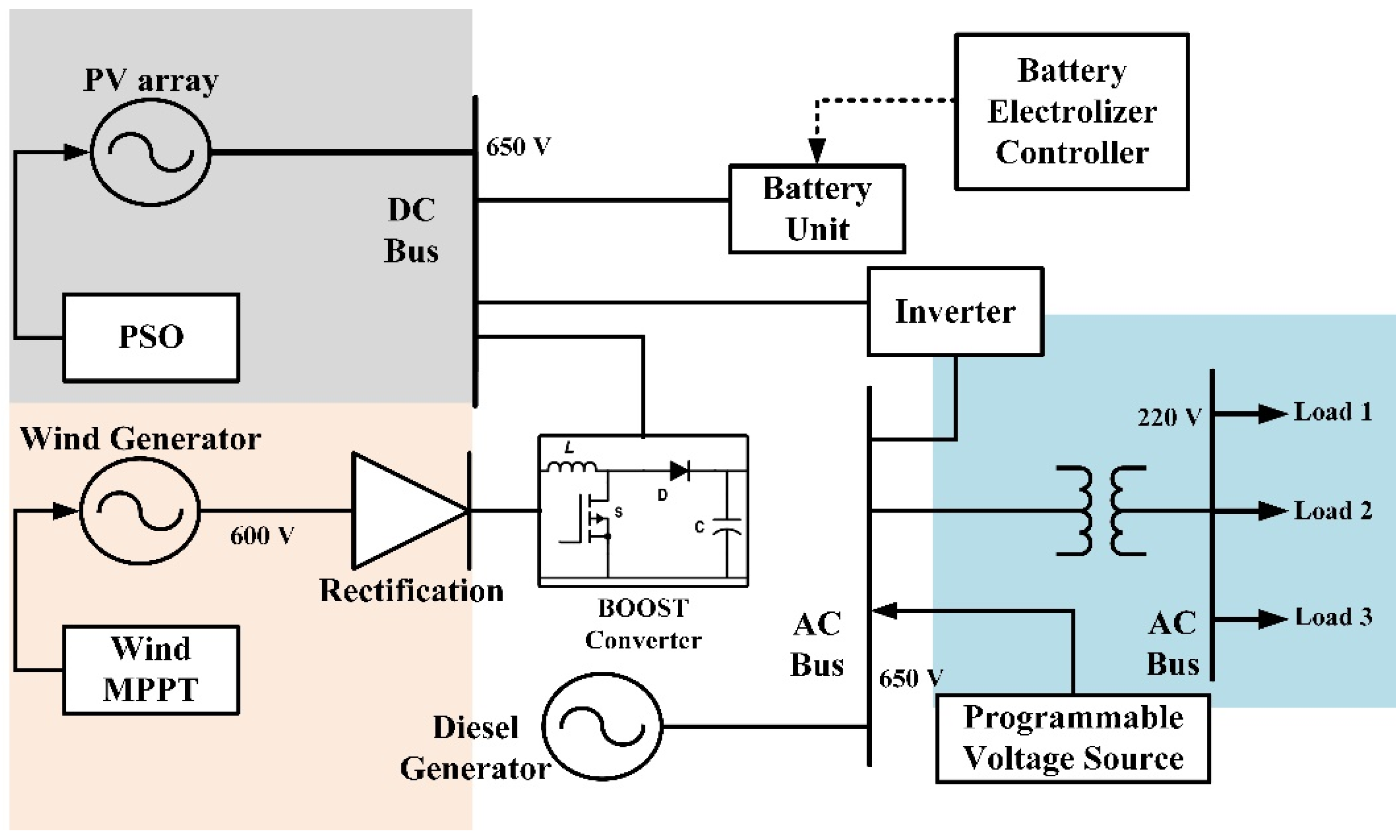
Figure 1 portrays a simple model of the proposed standalone IHMS along with the components and their mutual relationships. Solar PV modules generate direct current (DC) energy and battery devices store energy in DC form. This DC supply is converted into alternating current (AC) prior to being integrated with the AC bus utilizing suitable converter devices. On the contrary, wind turbines (WT) and diesel generators (DG) produce AC and may thus be simply integrated into the AC bus after a voltage adjustment using transformers. Within the microgrid, the AC and DC buses can therefore deliver electricity to AC and DC loads, respectively.

3. Methodology

3.1. Dispatch Algorithms

The “Dispatch” algorithm/methodology/strategy is a segment of the control framework which deals with the transfer of electrical power between components of the system [33]. This research considers five dispatch strategies: (i) cycle charging (CC), (ii) load following (LF), (iii) combined dispatch (CD), (iv) HOMER Predictive dispatch (PS) and (v) generator order (GO) strategy has been discussed and implemented [34,35].
CC strategy makes the power generator work at its rated power whenever it is needed. The surplus energy in this situation is utilized for charging the storage devices. The CC dispatch approach is most appropriate for networks with no renewable energy resources.
When a power generator is required, the LF dispatch approach ensures that enough power is available to meet the demand. In LF, the load needs to be met by sustainable sources for network feasibility and stability [36,37].
CD technique avoids the upcoming total load assumption. CD utilizes the current net demand estimation to decide whether to charge the battery utilizing the generator. In low demand, the usage of generators is skipped in the CD strategy. It chooses the cheaper choice to follow LF or CC in each time-lapse.
The GO method, on the other hand, picks a generator combination to satisfy the load that meets the operational capacity first, from a predetermined sequence of generator combinations [38,39].
In PS, the future accessibility of the wind and solar resources and probable upcoming load data are already approximated. The utilization of this methodology reduces the net cost of operation of the network [40,41].
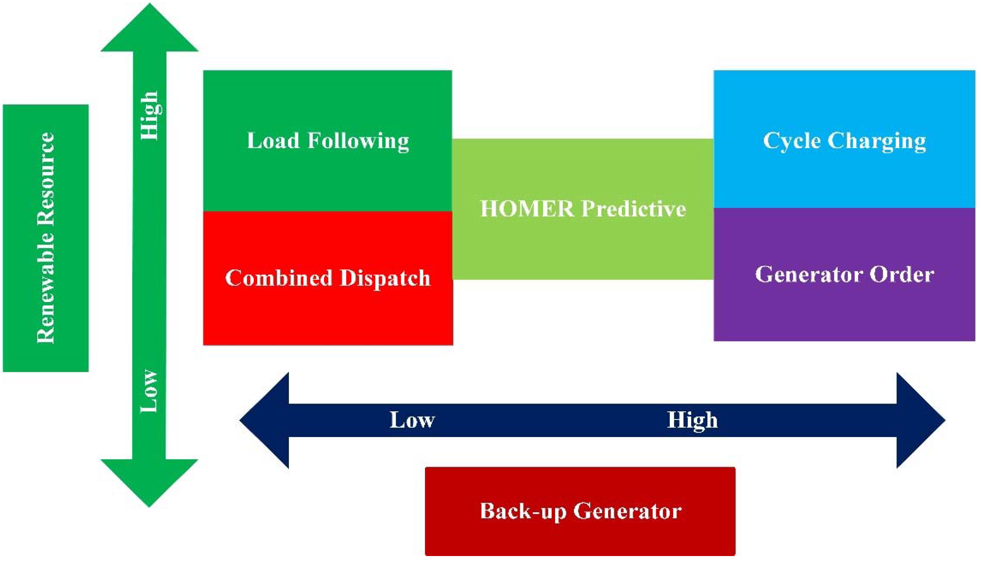
Dispatch methodologies provide the directions towards the energy management and optimized sizing of a standalone microgrid. When the situation is serious and availability to renewable sources and/or customer demand is sudden, how each of the five dispatch strategies uses the backup diesel generator is essential. Figure 2 depicts the operating sequence’s priority based on the five dispatch algorithms to show the perception of resources and a backup generator. Whenever the renewable resource is high, LF and CC have higher impact on the microgrid. The need for back-up DG is least in LF and, in CC, it is the highest. On the contrary, when the renewable sources are comparatively lower, the impact of CD and GO strategy is the lowest on the microgrid. HOMER PS strategy, on the other hand, stays in a medium position in respect to renewable resource utilization and backup generation implementation.

3.2. Formulation of Problem

3.2.1. Objective Function

The purpose of utilizing ED approaches in the optimization of microgrids is to minimize the microgrid’s expenses in a sustainable manner [24]. A single quadratic function may represent the objective function of conventional ED problems approximately as given in the following equation [18,42,43,44].
min cos t = j = 1 N g e n F j ( P j )
where
F j ( P j ) = a j + b j P j + c j P j 2
where Ngen = number of generator units, aj, bj, cj are fuel cost coefficients of the jth generator, Fj(Pj) = cost function of fuel of the jth generator in USD/hour, Pj = power output of the jth generator in MW.

3.2.2. Equality Inequality Constraints

Following constraints are needed to be satisfied by ED problems.

Active Power Balance Constraint

The net system loss (Ploss) plus the net consumer demand (Pdemand) must equal net power output [18]:
j = 1 N g e n F j ( P j ) = P d e m a n d + P l o s s  
Now, Ploss is evaluated utilizing B coefficients:
P l o s s = i = 1 N g e n   j = 1 N g e n P i B i j P j + i = 1 N g e n P i B 0 i + B 00
here Bij, B0i, B00 are coefficients of loss.

Constraints for Generation Capacity

P g e n ( i )   electricity generated from the ith generator must equal to or higher than the lowest generation range,   P g e n . m i n ( i ) and equal to or less than the highest source capacity P g e n . m a x ( i ) [18,42,44]:
Subject to
P g e n . m i n ( i ) P g e n ( i ) P g e n . m a x ( i )  
The combined net power losses ( P l o s s e s ), net load demand ( P d e m a n d ) and storage power ( P s t o r a g e ) needs to be equal to the net generated power [18]:
i P g e n ( i ) = P d e m a n d + P l o s s e s + P s t o r a g e

3.2.3. Cost Function Minimization and Optimal Sizing

To get the ideal component capacities and the required quantity of power generating equipment, the optimization problems (Equations (7)–(10)) must be solved [45].
m i n a , b , c , d , f 1 N ° ( f 1 ( a × L C O E P V + b × L C O E W T + c × L C O E D G + d × L C O E B T ) )  
m i n a , b , c , d , f 2 N ° ( f 2 ( a × N P C P V + b × N P C W T + c × N P C D G + d × N P C B T ) )  
m i n f 3 N ° ( f 3 ( e C O 2 D G ) )  
m i n f 1 , f 2 , f 3 , N ° ( f 1 × L C O E T o t a l + f 2 × N P C T o t a l + f 3 × G H G T o t a l )
In the equation, a, b, c, d are corresponding capacities of various microgrid components, and f1, f2, f3 are weights to mean the corresponding component’s significance. NPC refers to the corresponding equipment’s net present cost, LCOE refers to the corresponding equipment’s levelized cost of energy, eCO2 and GHG refer to the quantity of carbon-di-oxide and greenhouse gas release by the hybrid microgrid, respectively.

3.2.4. COE Calculation

Microgrid’s cost of energy (COE) can be evaluated utilizing HOMER following [46]:
C O E = C a n n u a l L p r i m a r y + L d + E g s
In this equation, Cannual = yearly net cost, Lprimary = net primary demand, Egs = net energy brought by the traditional grid each year, Ld = net deferrable demand.

3.2.5. NPC Calculation

NPC of an IHMS can be evaluated using the following equation [46]:
C N P C = C a n n u a l C R F ( i , T p r o j e c t )
here, i = rate of interest (annualized), Cannual = annual net cost, Tproject = longevity of the project, CRF (.) = capital recovery factor.

3.2.6. Evaluation of CO2 Release

CO2 release from the IHMS can be quantified by the equation below [46]:
e C O 2 = 3.667 × m f u e l × F H V × C E F f u e l × X c
In the equation, eCO2 = amount of CO2 gas, mfuel = amount of fuel in Liter, FHV = Fuel heating value in MJ/L, CEFfuel = carbon emission factor in ton carbon/TJ, Xc = oxidized carbon fraction. To estimate the carbon emission, the fact “3.667 g of CO2 contains 1 g of carbon” needs to be taken into consideration.

3.2.7. Evaluation of ED

Following equations formulate ED problems as optimization problems [47]:
m i n P G i i C G i P G i
Subject to,
P G i m i n P G i P G i m a x
i P G i = P D
The objective function mentioned in Equation (14) minimizes the cost of power production. In the equation, CGI refers marginal cost of every generation unit and PGI refers to the quantity of power that produces. Equation (15) demands that all generation units must stay within their max or min limits, and Equation (16) stipulates that the net produced energy must be equal to demand, PD.

3.2.8. Stabilization of Frequency

The frequency nadir (fnadir) and the post-fault RoCoF (Rate of Change of Frequency), must both be kept within their inceptions to achieve a stable microgrid frequency [48]:
| R o C o F | R o C o F m a x ,   f m i n i m u m f n a d i r f m a x i m u m
The IHMS’s frequency may be controlled by:
2 H d Δ f ( t ) d t =   i Δ P G i ( t ) +   j Δ P S j ( t ) D Δ f ( t ) P M
In this equation, H = microgrid’s inertia, D = load damping factor, Δf (t) = frequency deviation, ΔPGi (t) and ΔPSj (t) power differences of generation unit i and battery j respectively, PM = microgrids power imbalance.

3.2.9. Voltage Stabilization

Equation (19) can be used as the optimal function to keep up the ideal steady voltage [47]:
m i n Σ i ( V i V s e t p o , i ) 2
In this equation, specific nodal voltage, Vi, and the reference voltage is Vset,i. The quadratic objective function, for the situation, assists in limiting voltage deviations from the reference voltage.
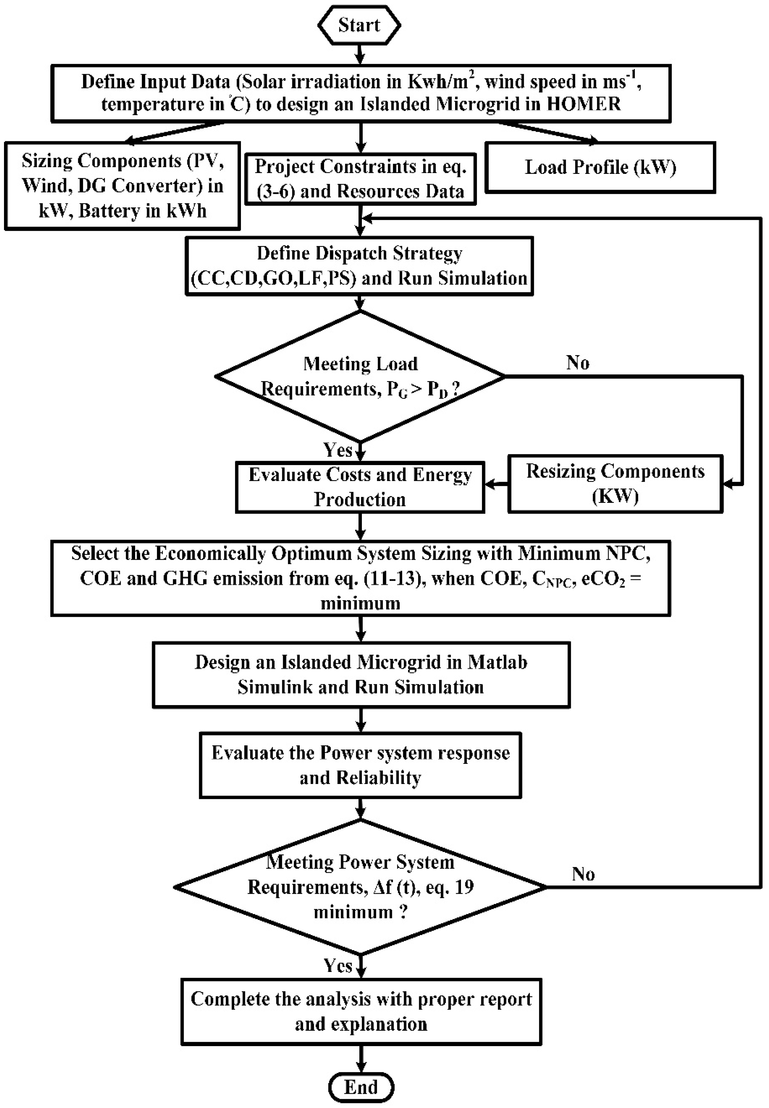
Figure 3 portrays a straight-line diagram representation for the proposed microgrids in Simulink analysis. The Simulink diagram combines diesel generator, solar PV, wind turbine, controllers, battery devices, loads, and converters, as shown in Figure 3. Figure 4 depicts the entire functional flow model for the intended microgrids for this research effort, demonstrating the optimization and assessment method. The cycle begins with the insertion of input quantities followed by technical and economic constraints, demand profile assessment, and then determining the dispatch methodologies in HOMER software. To determine the technical correctness of the proposed design, using Simulink, the simulated optimum sizes are classified and assessed with a proper power system analysis.

4. Results and Discussion

4.1. The IHMS’s Techno-Economic Study and Optimum Sizing

Table 1 contains the differences in COE, NPC, and CO2 release for different strategies for the proposed locations found from the HOMER analysis. LF has the least LCOE, NPC, and CO2 release of USD 0.208/kWh, USD 152,023 and 3375 kg/year and CD has the highest as respectively USD 0.532/kWh, USD 415,030, and 17,266 kg per year for Rajendro bazar and Kushighat.
Figure 5 and Figure 6 portray the different expenses and CO2 release for five dispatch approaches for the proposed locations found from HOMER study in a per unit fashion. The result shows clear differences in expenses and emissions despite the identical load demand, due to variations in dispatch mechanism.
Table 2 demonstrates the ideal sizes of different microgrid components i.e., solar PV, storage, wind turbine, diesel generator, and converter optimum capacities from HOMER simulation.
Table 3 demonstrates the ideal sizes of different microgrid component sizes used in the Simulink study that makes the microgrid power system i.e., voltage, frequency outputs steady and within the allowable range. From this study it has been observed that the optimum sizes of the system components obtained from the HOMER study for an area, when implemented in Simulink microgrid model, do not give a possible, steady, and reliable power system output always. For this reason, the HOMER anticipated optimal sizes in Table 2 have been calibrated and reported in Table 3, on basis of the ‘trial and error’ method for a real-time power system study in Simulink. The changes have been marked in Table 3.
Figure 7 portrays the ideal component sizes for the optimum operation of the microgrid on the basis of five dispatch approaches for Rajendro bazar discovered by HOMER and Simulink for side by side comparison in a normalized way.
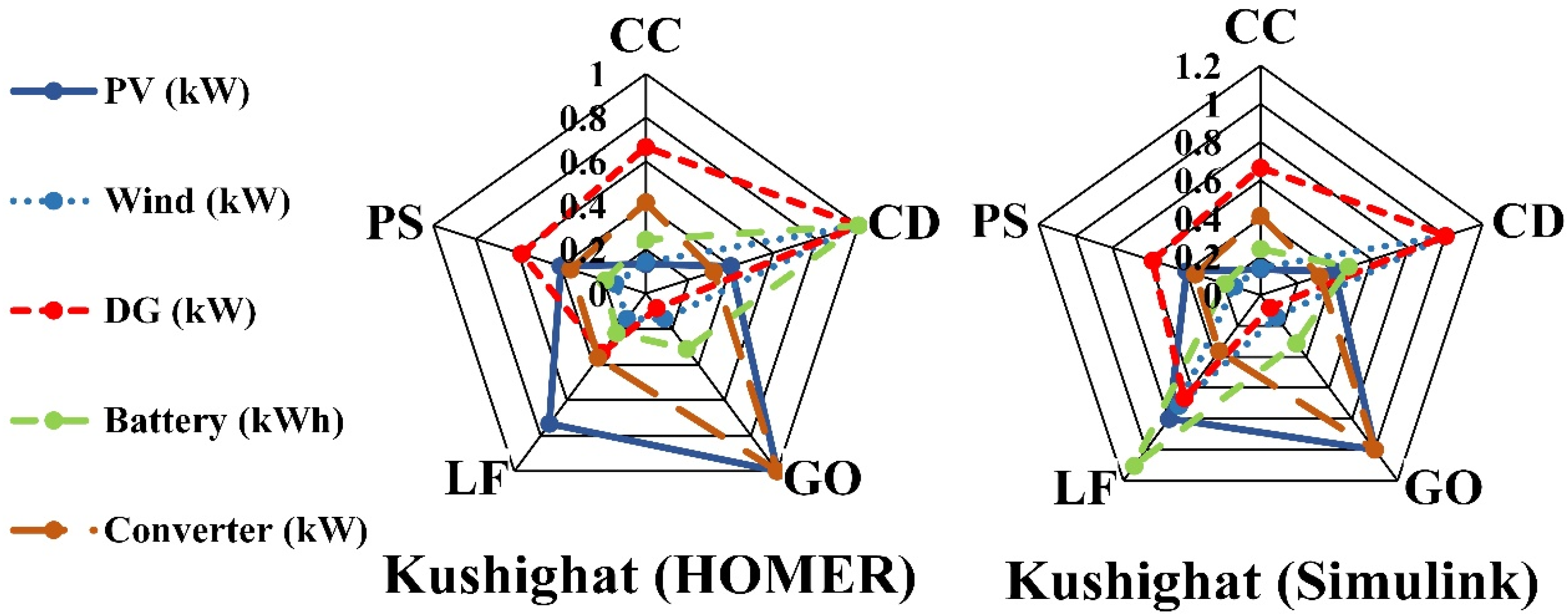
Figure 8 portrays the ideal component sizes for the optimal operation of the microgrid on the basis of five dispatch approaches for Kushighat discovered by HOMER and Simulink for side by side comparison in a normalized way.

4.2. Dispatch Strategy Based Voltage–Frequency Response of the Microgrids

This study refers to the stable and “within permissible limit” microgrid frequency and steady voltage output of distinct microgrid components produced from the Simulink microgrid model examination as “power system performance.” Different component sizes mentioned in Table 3 has been utilized with the Simulink microgrid model of Figure 3 and the steady microgrid responses have been obtained and will be demonstrated in the following segments:

4.2.1. Voltage Outputs

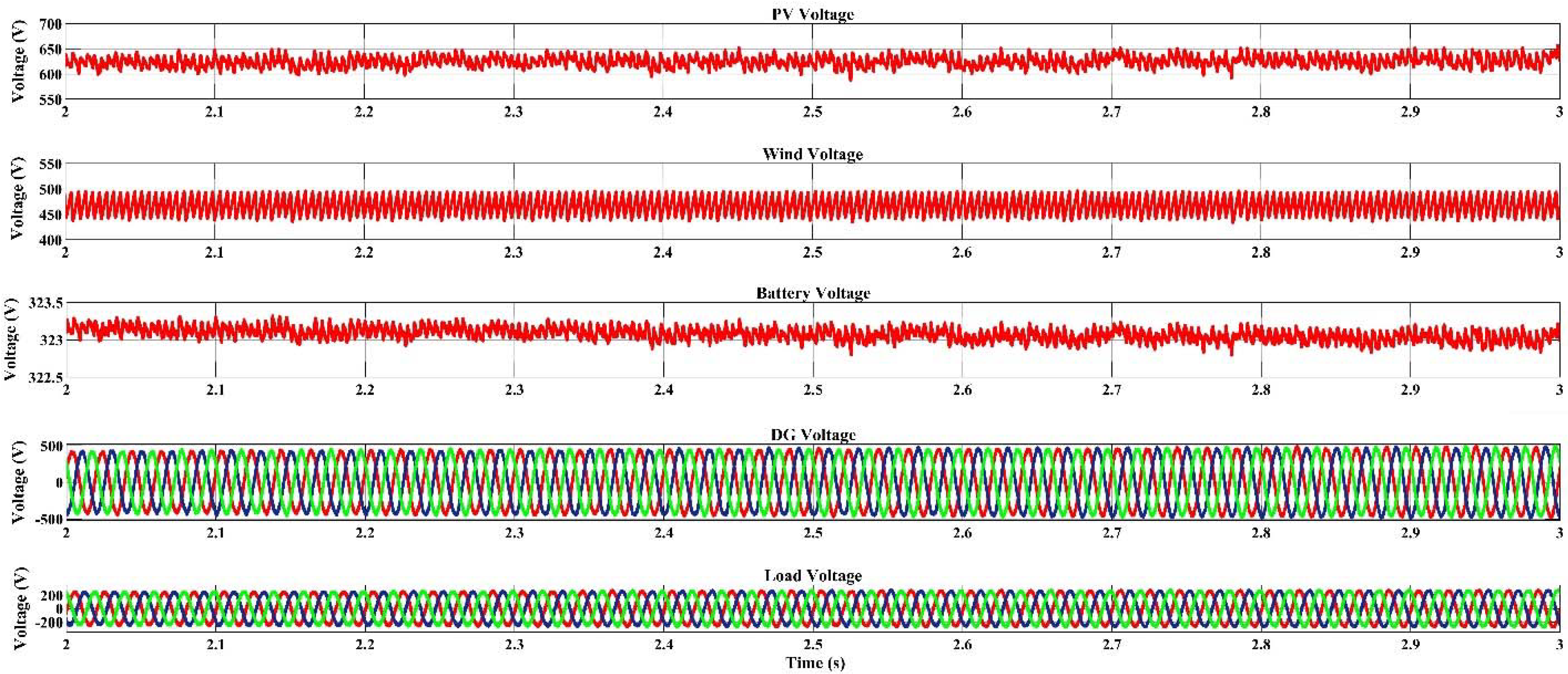
Figure 9 shows the voltage outputs for microgrid components i.e., battery, solar PV, wind turbine, load, and diesel generator voltage responses for Rajendro bazar for Cycle Charging strategy. All the above-mentioned voltage outputs are steady between the timeframe of 2 to 3 s. The PV voltage is steady between 650 V to 600 V, the 3 φ DG is steady with 1000 V (peak to peak), wind turbine voltage output is steady in between 500 V to 440 V, the battery voltage is steady within the range of 323.3 V to 322.7 V, and the 3 φ load is steady within 400 V (peak to peak) output.
Figure 10 shows the voltage responses for various components found for Rajendro bazar for the Combined Dispatch strategy. All the voltage outputs are steady between 2 to 3 s timeframe. The PV response is stable between 655 V to 600 V, wind turbine output is steady between 500 V to 440 V, the battery is steady within the range of 323.8 V to 323.6 V, the 3 φ DG output stays at 1000 V (peak to peak) and the 3 φ load is steady at 400 V (peak to peak).
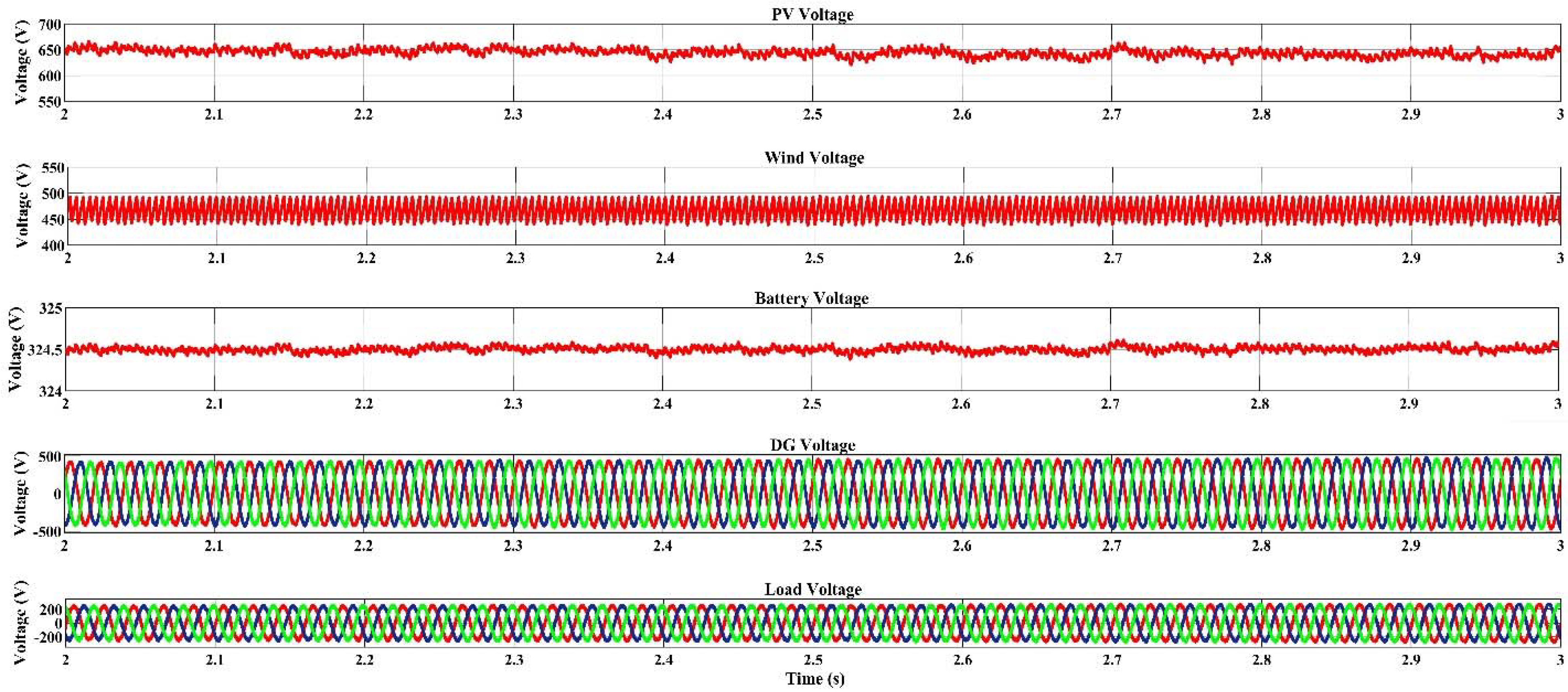
Figure 11 shows the voltage responses for various components found for Rajendro bazar for the Generator Order dispatch strategy. The PV response is steady between 660 V to 640 V, wind turbine output stays between 500 V to 440 V, the battery is steady between the voltage range of 324.6 V to 324.4 V, the 3 φ DG output is about 1000 V (peak to peak) and the 3 φ load stays steady with 400 V (peak to peak).
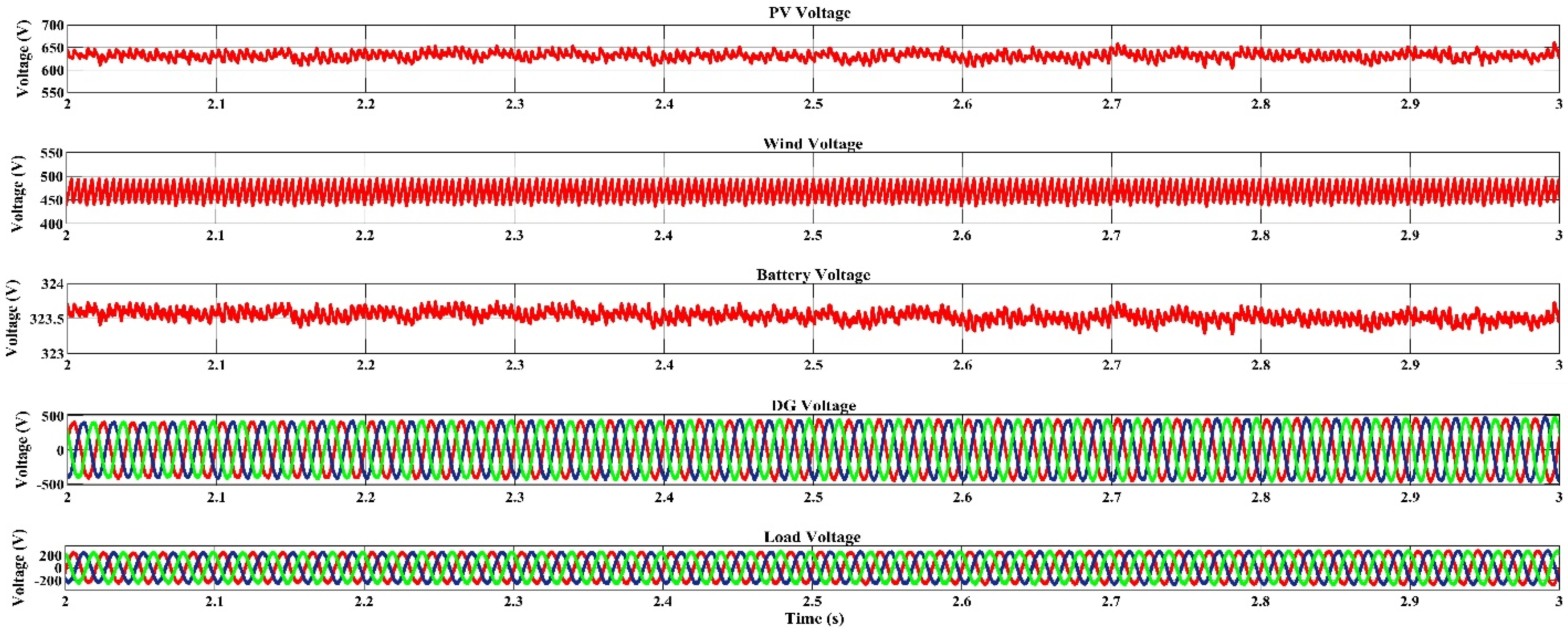
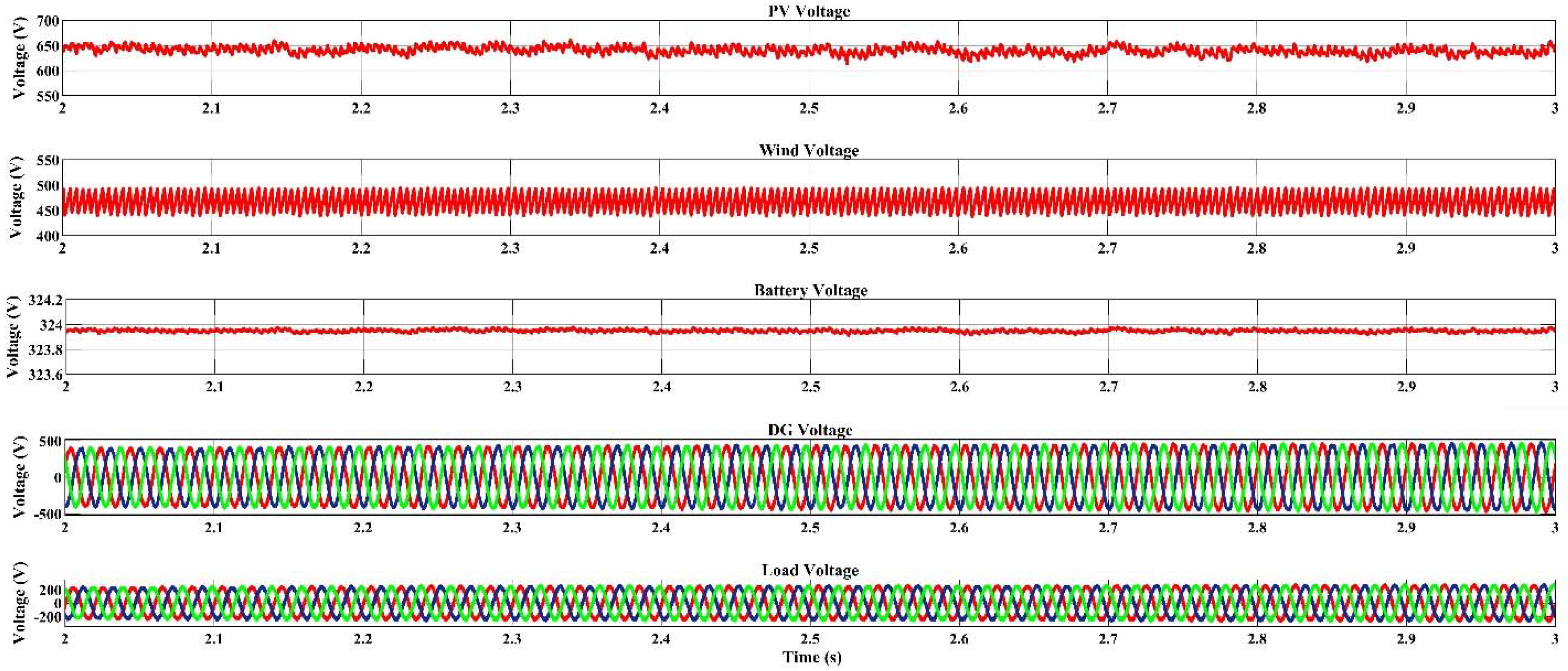
Figure 12 shows the voltage responses for various components found for Rajendro bazar for Load Following dispatch strategy. The solar PV has stable output within 660 V to 610 V, the wind turbine has a voltage between 500 V to 440 V, the battery output is stable between the range of 324 V to 323.9 V, the 3 φ DG has approximately 1000 V (peak to peak) voltage and the 3 φ load has a stable voltage of 400 V (peak to peak).
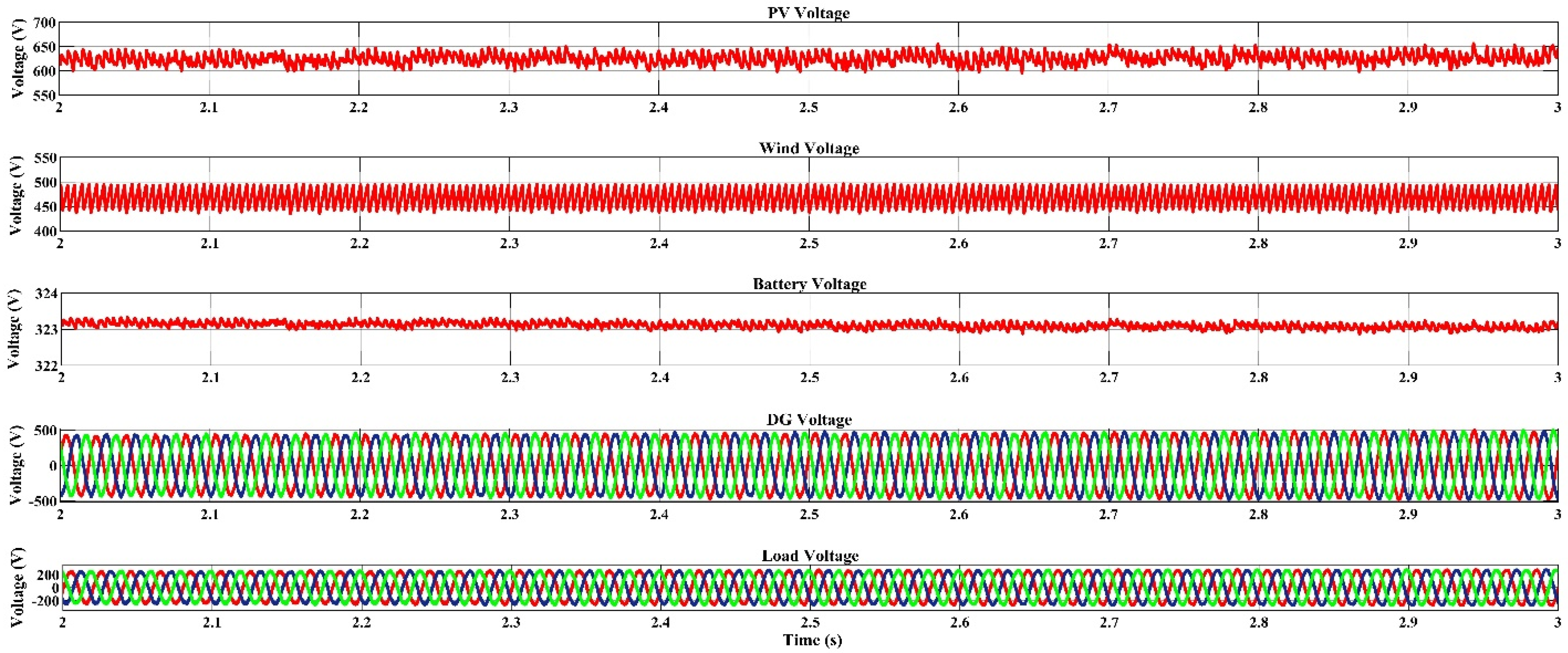
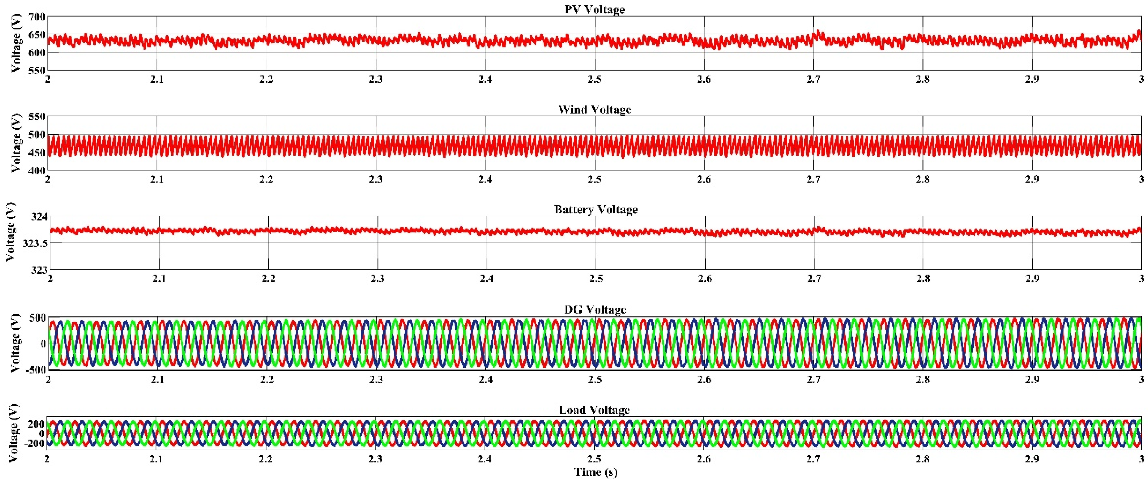
Figure 13 shows the voltage responses for various components found for Rajendro bazar for HOMER Predictive dispatch strategy. All the voltages are steady between 2 to 3 s. The PV response is staying between 650 V to 600 V, wind output is between 500 V to 440 V, the battery output is stable between the range of 323.7 V to 323.3 V, the 3 φ load has a voltage of 400 V (peak to peak) voltage and the 3 φ DG voltage stays at 1000 V (peak to peak).
Figure 14 shows the voltage responses for various components found for Kushighat for the Cycle Charging Dispatch strategy. All the voltage performances are steady between the time frame of 2 to 3 s. The PV response has a magnitude between 655 V to 600 V, the battery output is stable between the range of 323.4 V to 322.9 V, wind output is between 500 V to 440 V the 3 φ DG output stays at 1000 V (peak to peak) and the 3 φ load side voltage has magnitude at 400 V (peak to peak).
Figure 15 shows the voltage responses for various components found for Kushighat for the Combined Dispatch strategy. All the voltages are within the range of 2 to 3 s. The PV output is between 660 V to 600 V, the wind turbine has voltage magnitude between 500 V to 440 V, the battery output is stable between the range of 323.9 V to 323.6 V, the 3 φ DG output stays at 1000 V (peak to peak) and the 3 φ load has an output of 400 V (peak to peak).
Figure 16 shows the voltage responses for various components found for Kushighat for the Generator Order Dispatch strategy. All the voltages are steady within the time range of 2 to 3 s. The PV response stays in between 660 V to 620 V, wind output stays in between 500 V to 440 V, the battery output is stable between the range of 324.6 V to 324.4 V, the 3 φ DG output stays at 1000 V (peak to peak) and the 3 φ load voltage is settled at 400 V (peak to peak).
Figure 17 shows the voltage responses for various components found for Kushighat for Load Following dispatch strategy. All the voltage outputs are steady between 2 to 3 s. The PV response is steady between 660 V to 610 V, wind output is between 500 V to 440 V, the battery output is stable between the range of 324 V to 323.9 V, the 3 φ DG voltage stays at 1000 V (peak to peak) and the voltage of 3 φ load stays at 400 V (peak to peak).
Figure 18 shows the voltage responses for various components found for Kushighat for HOMER Predictive dispatch strategy. All the voltages stay between 2 to 3 s. The PV response stays between 655 V to 600 V, wind output stays in between 500 V to 440 V, the battery output voltage is steady within the range of 323.7 V to 323.3 V, the 3 φ DG output is at 1000 V (peak to peak) and the 3 φ load output is stable at 400 V (peak to peak).

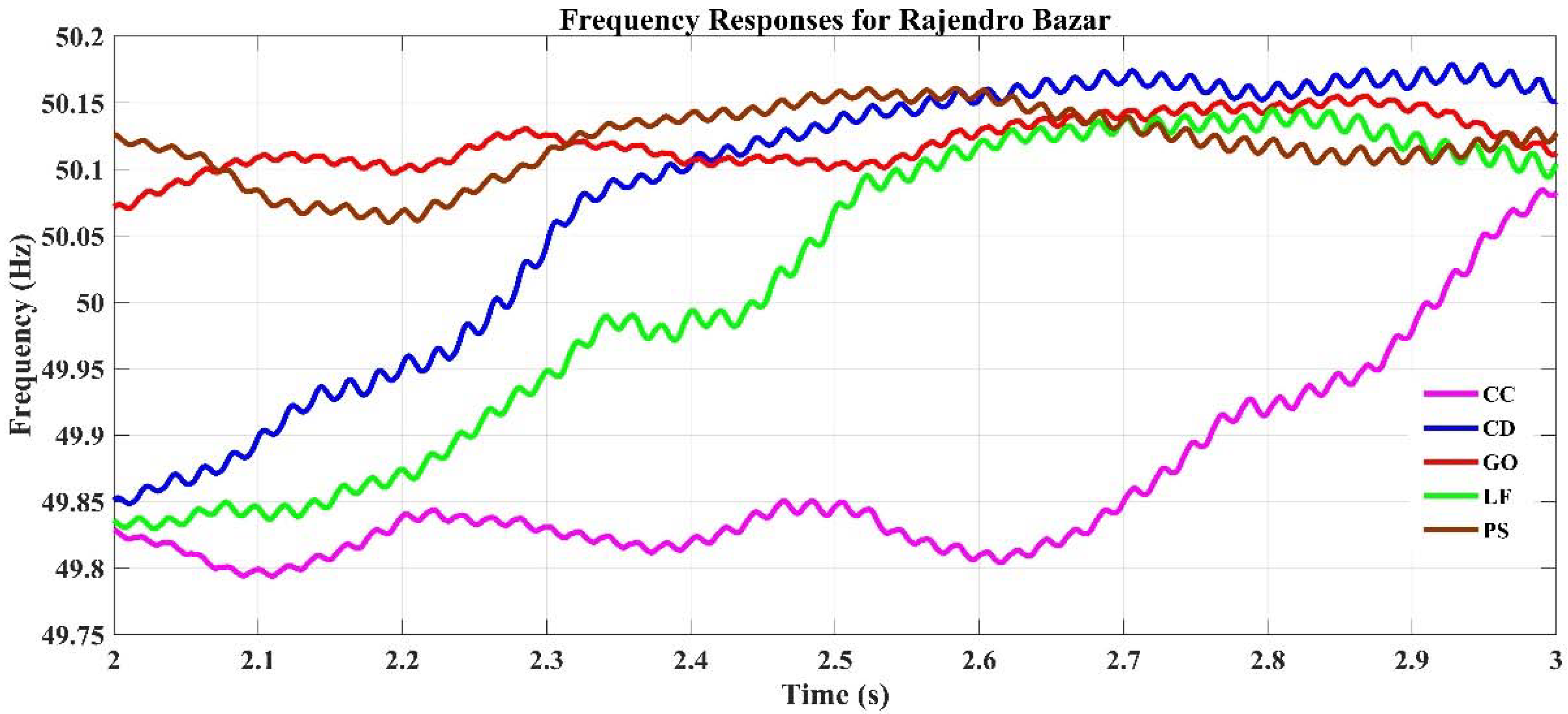
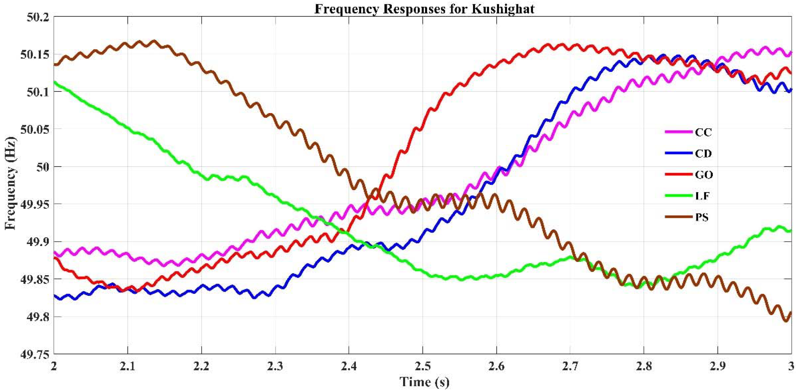
4.2.2. Frequency Output and Feasibility Study

Figure 19 portrays the frequency responses for Rajendro bazar for five alternative dispatch approaches. Despite several ups and downs within the frequency amplitudes over the time frame, the frequency response has been steady throughout the range of 2 to 3 s and stays between the ideal allowable range of 50 +/− 2% Hz. For Cycle Charging dispatch strategy, at time = 2 s, the frequency is about 49.82 Hz and the frequency at 3 s is about 50.09 Hz. For the Combined Dispatch strategy, at time = 2 s, the system frequency is about 49.85 Hz and about 50.15 Hz at 3 s. For the Generator Order Dispatch strategy, at time = 2 s the frequency is about 50.08 Hz and 50.11 Hz at 3 s. For Load Following strategy, the frequency is approximately 49.82 Hz, at time = 2 s, and at 3 s, it settles at about 50.10 Hz. For HOMER Predictive Dispatch strategy, at time = 2 s the frequency is 50.12 Hz and at 3 s frequency is about 50.12 Hz.
Figure 20 shows the microgrid frequency for the Kushighat for various dispatch approaches. Despite several ups and downs within the frequency amplitudes over the time frame, the frequency response has been steady throughout the range of 2 to 3 s and stays between the ideal allowable range of 50 +/− 2% Hz. At time = 2 s, the frequency of microgrid is 49.88 Hz and the frequency settles at up to 50.15 Hz in Cycle Charging strategy. For the Combined Dispatch strategy, at time = 2 s, the frequency of microgrid is 49.83 Hz and the frequency at 3 s is about 50.1 Hz. For the Generator Order Dispatch strategy, at time = 2 s, the frequency of microgrid is 49.88 Hz and at 3 s is about 50.13 Hz. For Load Following Dispatch strategy, at time = 2 s, the frequency of microgrid is 50.11 Hz and at 3 s, frequency is about 49.91 Hz. For HOMER Predictive dispatch strategy, at time = 2 s the frequency of microgrid is 50.14 Hz and after having a down-sided slope till time = 3 s, the frequency sets at 49.8 Hz.

4.3. Comparison

From the analysis, it can be observed that various costs for the proposed IHMS have been successfully minimized compared to the other Hybrid Renewable Energy Systems (HRES). Table 4 gives a short comparison between the intended IHMS and other HRES in terms of CO2 release, NPC, operating costs and COE. It can be deduced from the comparative table that there is a considerable difference between the proposed IHMS and other HRES. The comparison study respectively shows the COE of the developed IHMS is 88.92%, the NPC is 47.25%, the operating cost is 80.85%, and the CO2 release of the developed IHMS is 99.99% reduced than other optimized HRES. The comparison shown in Table 5 demonstrates that the COE of the optimized microgrid is 45.26%, the NPC is 48.80% and the CO2 release is 99.99% reduced compared to traditional power generation plants, respectively. The reason behind this improvement lies in the implementation of a dispatch strategy based control, and limiting the usage of diesel generator and keeping it only for backup power supply. The researchers in [46] did not implement DS based control which resulted in higher usage of diesel generator. On the other hand, conventional fossil fuel-based power generation stations do use fossil fuels and thus produce a huge amount of GHG.

4.4. Determining the Best and Worst Dispatch Approaches

Assessment of the simulated results in techno-economic perspective, power system response perspective, and environmental perspective it is evident that, LF approach can be declared as the best dispatch technique for all the performance evaluation criteria and on the contrary, for microgrid’s operation and sustainable optimization, the CD method is determined being the worst approach. GO on the other hand needs the highest PV and converter sizes. NPC and COE in GO strategy are higher than LF and lower than other strategies. In GO, the lowest sized DG of 1 kW is used, which results in the lowest carbon emission in this strategy. For Kushighat, GO offers a worse frequency response than LF and for Rajendro bazar, GO is better than LF. Considering costing, sizing, emissions and power system responses, overall, LF performs better than GO. Furthermore, based on the power system aspect, both PS and CC shows the worst responses because of the long-lasting instability and delays in mitigation of frequency and voltage stability.

4.5. Discussion on Results

The optimization results and system performances obtained in this research work are up to the mark and can be declared feasible and practically implementable. When there is enough power generation from renewable energy resources, the LF dispatch operates on the concept of first filling the principal loads. In this situation, the primary load refers to specialized or preset load needs, such as the residential load demand. In the LF approach, storage battery units and other deferrable load demands are given low priority. The CD dispatch method, on the other hand, is based on a system that determines the most cost-effective manner to pick either the LF or CC dispatch strategy. This results in higher system costs and component sizes, which may impair the output power system responsiveness. The recommended sites in this study provide sufficient renewable resources in the form of solar irradiation and wind speed, allowing the LF method to outperform other strategies for these specific locations. Alternatively, the CD approach picks the CC method in this study for the specified sites, degrading system responsiveness and optimal sizes. Furthermore, on the basis of the microgrid’s voltage and frequency results, both PS and CC methods have the lowest performance owing to the delay and long-term instability in frequency and voltage stability mitigation.

4.6. Advantages of the Proposed System

The proposed islanded microgrids have several advantages such as voltage and frequency stability under different stochastic conditions, least COE, CO2 release and NPC. Selection of the best dispatch controller was achieved through the comparative analysis of several dispatch techniques for the optimum operation of the islanded microgrid.

5. Conclusions

In this work, a wind/PV/batt/diesel generator-based off-grid hybrid microgrid has been designed for proposed locations. In this analysis, the optimal resource planning and dependable microgrid operation have been given importance. On the basis of a minimal cost of energy, CO2 release, net present cost and generally consistent voltage-frequency performances, the study of simulation data from HOMER and Matlab/Simulink for several dispatch algorithms suggests that load following is the best dispatch approach for the proposed locations. Combined dispatch is determined as the worst dispatch approach based on the highest net present cost, CO2 release, cost of energy and relatively poor voltage-frequency responses for the proposed microgrids. The energy cost of the planned hybrid microgrid is 88.92%, the net present cost is 47.25%, the cost of operation is 80.85% and the CO2 emission is 99.99% reduced compared to the other hybrid microgrid, respectively. The comparison study also shows that the energy cost of the proposed system is 45.26%, the net present cost is 48.80%, and the CO2 emission is 99.99% reduced compared to traditional power generation station. The power system (voltage and frequency) performance for the proposed microgrids, found through Simulink analysis, has also been studied in this research work. To guarantee a continuous power supply for the planned sites of Rajendro bazar and Kushighat, the proposed microgrids have met three primary requirements, including techno-economic feasibility and system stability (stable voltage and frequency outputs). This hybrid islanded microgrids, which have been designed and optimized, will be used mostly in islanded and isolated areas with similar load demand and meteorological status.

6. Limitations and Future Research Recommendations

The main limitations of this research are that the real-life line length data of the available distribution network are yet to be considered for more accurate results. More dynamic loads need to be considered and integrated into the system to monitor the voltage and frequency profile for practical application and, finally, multiple years of meteorological data need to be considered for evaluating the results under different stochastic conditions. All three points can be considered as future works to be done in further research papers.

Author Contributions

Data curation, M.F.I. and S.A.S.; Formal analysis, S.A.S.; Funding acquisition, S.M.M.; Investigation, M.F.I., S.A.S., M.S.R., A.R., S.M.M. and L.C.P.; Methodology, M.F.I. and S.A.S.; Software, S.A.S.; Supervision, S.A.S., M.S.R., A.R. and S.M.M.; Validation, M.F.I., S.A.S. and M.S.R.; Visualization, M.F.I. and S.A.S.; Writing—original draft, M.F.I.; Writing—review & editing, M.F.I., L.C.P. and M.S.I. All authors have read and agreed to the published version of the manuscript.

Funding

This publication has been funded by the corresponding author Prof. Dr. S M Muyeen ([email protected]: Qatar University).

Acknowledgments

The conducted research work has been facilitated by Qatar National Library and RMIT University.

Conflicts of Interest

The authors declare no conflict of interest.

Abbreviations

AbbreviationElaborative form
HOMERHybrid Optimization of Multiple Electric Renewables
NPCNet Present Cost
COECost of Energy
GHGGreen House Gas
BESSBattery Energy Storage System
ACAlternating Current
DCDirect Current
EDEconomic Dispatch
RTED Real Time Economic Dispatch
IHMSIntegrated Hybrid Microgrid System
WT Wind Turbines
DGDiesel Generator
PV Photo Voltaic
CC Cycle Charging
LF Load Following
CD Combined Dispatch
PSHOMER Predictive dispatch
GOGenerator Order
RoCoF Rate of Change of Frequency
HRESHybrid Renewable Energy Systems
Nomenclature
Ngennumber of generator units
aj, bj, cjfuel cost coefficients of the jth generator
Fj(Pj)cost function of fuel of the jth generator in USD/hour
Pjpower output of the jth generator in MW
Plossnet system loss
Pdemandnet consumer demand
Bij, B0i, B00coefficients of loss
P gen ( i )   electricity generated from the ith generator
P gen . min ( i )   lowest generation range,
P gen . max ( i ) highest source capacity
P storage storage power
a, b, c, dcorresponding capacities of various microgrid components
f1, f2, f3weights to mean the corresponding component’s significance
Cannualyearly net cost
Lprimarynet primary demand
Egsnet energy brought by the traditional grid each year
Ldnet deferrable demand
irate of interest (annualized)
Cannualannual net cost
Tprojectlongevity of the project
CRF (.)capital recovery factor
eCO2amount of CO2 gas
mfuelamount of fuel in Liter
FHVFuel heating value in MJ/L
CEFfuelcarbon emission factor in ton carbon/TJ
Xcoxidized carbon fraction
fnadirfrequency nadir
RoCoFRate of Change of Frequency
Hmicrogrid’s inertia
Dload damping factor
Δf (t)frequency deviation
PMmicrogrids power imbalance
ΔPSj (t)power differences of generation unit i
ΔPGi (t)power differences of battery j

References

  1. Ma, Y.; Chen, Y.; Chen, X.; Deng, F.; Song, X. Optimal Dispatch of Hybrid Energy Islanded Microgrid Considering V2G Under TOU Tariffs. E3S Web Conf. 2019, 107, 02007. [Google Scholar] [CrossRef]
  2. Nwani, C.; Omoke, P.C. Does bank credit to the private sector promote low-carbon development in Brazil? An extended STIRPAT analysis using dynamic ARDL simulations. Env. Sci. Pollut. Res. Int. 2020, 27, 31408–31426. [Google Scholar] [CrossRef]
  3. Chang, X.; Xu, Y.; Gu, W.; Sun, H.; Chow, M.-Y.; Yi, Z. Accelerated distributed hybrid stochastic/robust energy management of smart grids. IEEE Trans. Ind. Inform. 2020, 17, 5335–5347. [Google Scholar] [CrossRef]
  4. Mohamed, S.; Shaaban, M.F.; Ismail, M.; Serpedin, E.; Qaraqe, K.A. An efficient planning algorithm for hybrid remote microgrids. IEEE Trans. Sustain. Energy 2018, 10, 257–267. [Google Scholar] [CrossRef]
  5. Papari, B.; Edrington, C.S.; Bhattacharya, I.; Radman, G. Effective energy management of hybrid AC–DC microgrids with storage devices. IEEE Trans. Smart Grid 2017, 10, 193–203. [Google Scholar] [CrossRef]
  6. Duan, J.; Yi, Z.; Shi, D.; Lin, C.; Lu, X.; Wang, Z. Reinforcement-learning-based optimal control of hybrid energy storage systems in hybrid AC–DC microgrids. IEEE Trans. Ind. Inform. 2019, 15, 5355–5364. [Google Scholar] [CrossRef]
  7. Dabbaghjamanesh, M.; Kavousifard, A.; Mehraeen, S.; Zhang, J.; Dong, Z.Y. Sensitivity Analysis of Renewable Energy Integration on Stochastic Energy Management of Automated Reconfigurable Hybrid AC-DC Microgrid Considering DLR Security Constraint. IEEE Trans. Ind. Inform. 2019, 16, 120–131. [Google Scholar] [CrossRef]
  8. Shezan, S.A.; Ishraque, M.F. Assessment of a Micro-grid Hybrid Wind-Diesel-Battery Alternative Energy System Applicable for Offshore Islands. In Proceedings of the 2019 5th International Conference on Advances in Electrical Engineering (ICAEE), Dhaka, Bangladesh, 26–28 September 2019; pp. 457–462. [Google Scholar]
  9. Barbaro, M.; Castro, R. Design optimisation for a hybrid renewable microgrid: Application to the case of Faial island, Azores archipelago. Renew. Energy 2020, 151, 434–445. [Google Scholar] [CrossRef]
  10. Ishraque, M.F.; Shezan, S.A.; Nur, J.N.; Islam, M.S. Optimal Sizing and Assessment of an Islanded Photovoltaic-Battery-Diesel Generator Microgrid Applicable to a Remote School of Bangladesh. Eng. Rep. 2021, 3, e12281. [Google Scholar] [CrossRef]
  11. Ishraque, M.F.; Ali, M.M. Optimized Design of a Hybrid Microgrid using Renewable Resources Considering Different Dispatch Strategies. In Proceedings of the 2021 International Conference on Automation, Control and Mechatronics for Industry 4.0 (ACMI), Rajshahi, Bangladesh, 8–9 July 2021; pp. 1–6. [Google Scholar]
  12. Liu, B.; Liu, S.; Guo, S.; Zhang, S. Economic study of a large-scale renewable hydrogen application utilizing surplus renewable energy and natural gas pipeline transportation in China. Int. J. Hydrog. Energy 2020, 45, 1385–1398. [Google Scholar] [CrossRef]
  13. Shezan, S.A.; Saidur, R.; Ullah, K.; Hossain, A.; Chong, W.T.; Julai, S. Feasibility analysis of a hybrid off-grid wind–DG-battery energy system for the eco-tourism remote areas. Clean Technol. Environ. Policy 2015, 17, 2417–2430. [Google Scholar] [CrossRef]
  14. Li, P.; Liu, Y.; Xin, H.; Jiang, X. A Robust Distributed Economic Dispatch Strategy of Virtual Power Plant Under Cyber-Attacks. IEEE Trans. Ind. Inform. 2018, 14, 4343–4352. [Google Scholar] [CrossRef]
  15. Barley, C.D.; Winn, C.B. Optimal dispatch strategy in remote hybrid power systems. Sol. Energy 1996, 58, 165–179. [Google Scholar] [CrossRef]
  16. Jiang, K.; Wu, F.; Zong, X.; Shi, L.; Lin, K. Distributed Dynamic Economic Dispatch of an Isolated AC/DC Hybrid Microgrid Based on a Finite-Step Consensus Algorithm. Energies 2019, 12, 4637. [Google Scholar] [CrossRef] [Green Version]
  17. Coelho, L.S.; Mariani, V.C. Combining of chaotic differential evolution and quadratic programming for economic dispatch optimization with valve-point effect. IEEE Trans. Power Syst. 2006, 21, 989–996. [Google Scholar]
  18. Xiong, G.; Shi, D.; Duan, X. Multi-strategy ensemble biogeography-based optimization for economic dispatch problems. Appl. Energy 2013, 111, 801–811. [Google Scholar] [CrossRef]
  19. Augustine, N.; Suresh, S.; Moghe, P.; Sheikh, K. In Economic dispatch for a microgrid considering renewable energy cost functions. In Proceedings of the 2012 IEEE PES Innovative Smart Grid Technologies (ISGT), Washington, DC, USA, 16–20 January 2012; pp. 1–7. [Google Scholar]
  20. Zhu, J.; Zhu, T.; Mo, X.; Liu, M. A spatiotemporal decomposition algorithm for fully decentralized dynamic economic dispatch in a microgrid. Electr. Power Syst. Res. 2020, 185, 106361. [Google Scholar] [CrossRef]
  21. Gil-González, W.; Montoya, O.D.; Grisales-Noreña, L.F.; Cruz-Peragón, F.; Alcalá, G. Economic Dispatch of Renewable Generators and BESS in DC Microgrids Using Second-Order Cone Optimization. Energies 2020, 13, 1703. [Google Scholar] [CrossRef] [Green Version]
  22. Ross, D.W.; Kim, S. Dynamic economic dispatch of generation. IEEE Trans. Power Appar. Syst. 1980, 6, 2060–2068. [Google Scholar] [CrossRef]
  23. Tang, C.; Zhang, F.; Zhao, Z. Real-Time Economic Dispatch and Subinterval Coordination Strategy to Benefit System Operations. In Proceedings of the 2019 IEEE Innovative Smart Grid Technologies-Asia (ISGT Asia), Chengdu, China, 21–24 May 2019; pp. 2881–2886. [Google Scholar]
  24. Liu, W.; Zhuang, P.; Liang, H.; Peng, J.; Huang, Z. Distributed economic dispatch in microgrids based on cooperative reinforcement learning. IEEE Trans. Neural Netw. Learn. Syst. 2018, 29, 2192–2203. [Google Scholar] [CrossRef]
  25. Mohy-ud-din, G.; Muttaqi, K.M.; Sutanto, D. An Effective Power Dispatch Strategy to Improve Generation Schedulability by Mitigating Wind power Uncertainty with a Data Driven flexible Dispatch Margin for a Wind Farm using a Multi-Unit Battery Energy Storage System. In Proceedings of the 2018 IEEE Industry Applications Society Annual Meeting (IAS), Portland, OR, USA, 23–27 September 2018; pp. 1–8. [Google Scholar]
  26. Wang, R.; Li, Q.; Li, G.; Liu, H. A Gossip-Based Distributed Algorithm for Economic Dispatch in Smart Grids With Random Communication Link Failures. IEEE Trans. Ind. Electron. 2019, 67, 4635–4645. [Google Scholar] [CrossRef]
  27. Das, B.K.; Zaman, F. Performance analysis of a PV/Diesel hybrid system for a remote area in Bangladesh: Effects of dispatch strategies, batteries, and generator selection. Energy 2019, 169, 263–276. [Google Scholar] [CrossRef]
  28. Xu, Y.; Sun, H.; Gu, W.; Xu, Y.; Li, Z. Optimal distributed control for secondary frequency and voltage regulation in an islanded microgrid. IEEE Trans. Ind. Inform. 2018, 15, 225–235. [Google Scholar] [CrossRef]
  29. Fatin Ishraque, M.; Shezan, S.A.; Ali, M.M.; Rashid, M.M. Optimization of load dispatch strategies for an islanded microgrid connected with renewable energy sources. Appl. Energy 2021, 292, 116879. [Google Scholar] [CrossRef]
  30. Ishraque, M.F.; Shezan, S.A.; Rashid, M.M.; Bhadra, A.B.; Hossain, M.A.; Chakrabortty, R.K.; Ryan, M.J.; Fahim, S.R.; Sarker, S.K.; Das, S.K. Techno-Economic and Power System Optimization of a Renewable Rich Islanded Microgrid Considering Different Dispatch Strategies. IEEE Access 2021, 9, 77325–77340. [Google Scholar] [CrossRef]
  31. NASA. Available online: https://power.larc.nasa.gov/ (accessed on 20 February 2021).
  32. He, Y.; Wang, W.; Wu, X. Multi-Agent Based Fully Distributed Economic Dispatch in Microgrid Using Exact Diffusion Strategy. IEEE Access 2020, 8, 7020–7031. [Google Scholar] [CrossRef]
  33. Ashari, M.; Nayar, C.V. An optimum dispatch strategy using set points for a photovoltaic (PV)–diesel–battery hybrid power system. Sol. Energy 1999, 66, 1–9. [Google Scholar] [CrossRef]
  34. Xu, H.; Meng, Z.; Zhao, R.; Wang, Y.; Yan, Q. Optimal Dispatching Strategy of an Electric-Thermal-Gas Coupling Microgrid Considering Consumer Satisfaction. IEEE Access 2020, 8, 173169–173176. [Google Scholar] [CrossRef]
  35. Wu, N.; Wang, H.; Yin, L.; Yuan, X.; Leng, X. Application Conditions of Bounded Rationality and a Microgrid Energy Management Control Strategy Combining Real-Time Power Price and Demand-Side Response. IEEE Access 2020, 8, 227327–227339. [Google Scholar] [CrossRef]
  36. Zhang, Z.; Wang, Z.; Wang, H.; Zhang, H.; Yang, W.; Cao, R. Research on Bi-Level Optimized Operation Strategy of Microgrid Cluster Based on IABC Algorithm. IEEE Access 2021, 9, 15520–15529. [Google Scholar] [CrossRef]
  37. Dong, X.; Li, X.; Cheng, S. Energy Management Optimization of Microgrid Cluster Based on Multi-Agent-System and Hierarchical Stackelberg Game Theory. IEEE Access 2020, 8, 206183–206197. [Google Scholar] [CrossRef]
  38. Xi, L.; Zhang, L.; Liu, J.; Li, Y.; Chen, X.; Yang, L.; Wang, S. A Virtual Generation Ecosystem Control Strategy for Automatic Generation Control of Interconnected Microgrids. IEEE Access 2020, 8, 94165–94175. [Google Scholar] [CrossRef]
  39. Malik, M.M.; Kazmi, S.A.A.; Asim, H.W.; Ahmed, A.B.; Shin, D.R. An Intelligent Multi-Stage Optimization Approach for Community Based Micro-Grid Within Multi-Microgrid Paradigm. IEEE Access 2020, 8, 177228–177244. [Google Scholar] [CrossRef]
  40. Pro, H. Available online: https://www.homerenergy.com/products/pro/docs/latest/predictive_dispatch.html#:~:text=Under%20the%20HOMER%20Predictive%20dispatch,dispatch%20strategies%20in%20HOMER%20Pro (accessed on 20 October 2020).
  41. Moretti, L.; Polimeni, S.; Meraldi, L.; Raboni, P.; Leva, S.; Manzolini, G. Assessing the impact of a two-layer predictive dispatch algorithm on design and operation of off-grid hybrid microgrids. Renew. Energy 2019, 143, 1439–1453. [Google Scholar] [CrossRef]
  42. Xu, Q.; Xiao, J.; Wang, P.; Wen, C. A decentralized control strategy for economic operation of autonomous AC, DC, and hybrid AC/DC microgrids. IEEE Trans. Energy Convers. 2017, 32, 1345–1355. [Google Scholar] [CrossRef]
  43. Ahmad, J.; Tahir, M.; Mazumder, S.K. Dynamic economic dispatch and transient control of distributed generators in a microgrid. IEEE Syst. J. 2018, 13, 802–812. [Google Scholar] [CrossRef]
  44. Zhou, Q.; Shahidehpour, M.; Li, Z.; Che, L.; Alabdulwahab, A.; Abusorrah, A. Compartmentalization Strategy for the Optimal Economic Operation of a Hybrid AC/DC Microgrid. IEEE Trans. Power Syst. 2019, 35, 1294–1304. [Google Scholar] [CrossRef]
  45. Arefin, S.S. Optimization Techniques of Islanded Hybrid Microgrid System. In Renewable Energy-Resources, Challenges and Applications; IntechOpen: Hague, The Netherlands, 2020. [Google Scholar]
  46. Shezan, S.A.; Julai, S.; Kibria, M.A.; Ullah, K.R.; Saidur, R.; Chong, W.T.; Akikur, R.K. Performance analysis of an off-grid wind-PV (photovoltaic)-diesel-battery hybrid energy system feasible for remote areas. J. Clean. Prod. 2016, 125, 121–132. [Google Scholar] [CrossRef]
  47. Chatzivasileiadis, S. Optimization in modern power systems. Lecture Notes Tech. Univ. Den. 2018. Available online: https://arxiv.org/pdf/1811.00943.pdf (accessed on 20 June 2021).
  48. Wen, Y.; Chung, C.; Liu, X.; Che, L. Microgrid dispatch with frequency-aware islanding constraints. IEEE Trans. Power Syst. 2019, 34, 2465–2468. [Google Scholar] [CrossRef]
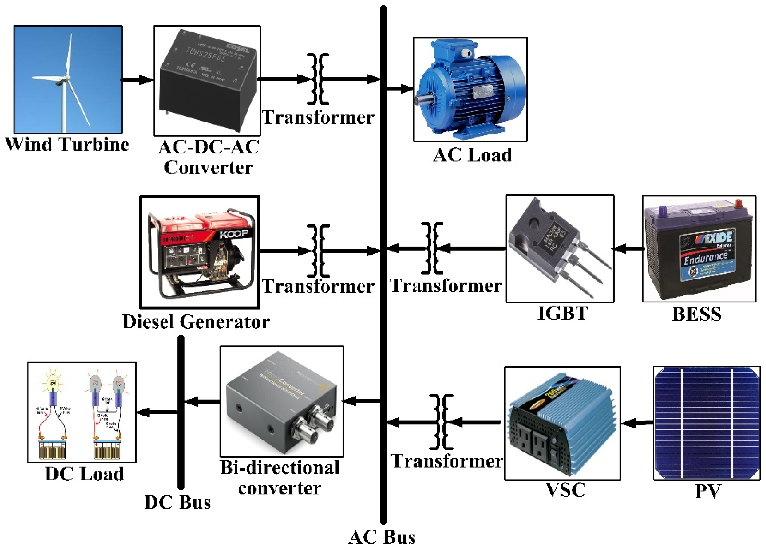
Figure 1. Block representation of the proposed IHMS.
Sustainability 13 12734 g001
Figure 2. Influence of sustainable resources and diesel generator for various dispatch strategies for proposed IHMS.
Sustainability 13 12734 g002
Figure 3. Line model for the designed microgrids.
Sustainability 13 12734 g003
Figure 4. Flow diagram showing optimization and assessment method.
Sustainability 13 12734 g004
Figure 5. Normalized expenses and emission for Rajendro bazar for different dispatch approaches.
Sustainability 13 12734 g005
Figure 6. Normalized expenses and emission for Kushighat for different dispatch approaches.
Sustainability 13 12734 g006
Figure 7. Ideal component sizes for Rajendro bazar (Normalized).
Sustainability 13 12734 g007
Figure 8. Ideal component sizes for Kushighat (Normalized).
Sustainability 13 12734 g008
Figure 9. Voltage Responses for Rajendro bazar CC.
Sustainability 13 12734 g009
Figure 10. Voltage Responses for Rajendro bazar CD.
Sustainability 13 12734 g010
Figure 11. Voltage Responses for Rajendro bazar GO.
Sustainability 13 12734 g011
Figure 12. Voltage Responses for Rajendro bazar LF.
Sustainability 13 12734 g012
Figure 13. Voltage Responses for Rajendro bazar PS.
Sustainability 13 12734 g013
Figure 14. Voltage Responses for Kushighat CC.
Sustainability 13 12734 g014
Figure 15. Voltage Responses for Kushighat CD.
Sustainability 13 12734 g015
Figure 16. Voltage Responses for Kushighat GO.
Sustainability 13 12734 g016
Figure 17. Voltage Responses for Kushighat LF.
Sustainability 13 12734 g017
Figure 18. Voltage Responses for Kushighat PS.
Sustainability 13 12734 g018
Figure 19. Frequency responses for Rajendro bazar for different dispatch approaches.
Sustainability 13 12734 g019
Figure 20. Frequency responses for Kushighat for various dispatch approaches.
Sustainability 13 12734 g020
Table 1. Variations in costs and emissions from HOMER.
Rajendro Bazar
Dispatch MethodologyNPC (USD)Operating Cost
(USD/year)
COE (USD/kWh)CO2 Emission (kg/year)
LF152,02337380.2083375
CD343,99614,6540.44020,961
CC302,95318,8500.38838,272
GO171,67827600.2360
PS191,59394050.24516,797
Kushighat
Dispatch MethodologyNPC (USD)Operating Cost
(USD/year)
COE (USD/kWh)CO2 Emission (kg/year)
LF157,56144560.2155035
CD415,03015,3940.53217,266
CC311,01519,3490.39839,159
GO181,44930390.2500
PS202,67710,2630.25918,891
Table 2. Optimum Component Sizes obtained from HOMER.
Rajendro Bazar
Dispatch MethodologyPV (kW)Wind (kW)DG (kW)Battery (kWh)Converter (kW)
LF553313813.9
CD2541238821.9
CC102813215.6
GO751115841.8
PS301711013.9
Kushighat
Dispatch MethodologyPV (kW)Wind (kW)DG (kW)Battery (kWh)Converter (kW)
LF551412914.3
CD3071257812.6
CC101814116.3
GO751118139.4
PS301711013.9
Table 3. Optimal Component Sizes used in Simulink.
Rajendro Bazar
Dispatch MethodologyPV (kW)Wind (kW)DG (kW)Battery (kWh)Converter (kW)
LF6058638.713.9
CD25412386.821.9
CC102813215.6
GO751118041.8
PS3017110.813.9
Kushighat
Dispatch MethodologyPV (kW)Wind (kW)DG (kW)Battery (kWh)Converter (kW)
LF6058638.714.3
CD30712275.412.6
CC101813916.3
GO751118139.4
PS3017110.813.9
Table 4. Comparison between the proposed and other HRES design.
ParametersDesigned IHMSOther HRES [46]
CO2 release/Year (Kt)0.003375198,347.984
Operating Cost (USD)373819,516
NPC/Year (USD)152,023288,194
COE (USD/kWh)0.2081.877
Table 5. Comparison between proposed microgrid and traditional power station.
ParametersDesigned IHMSTraditional Power Station [46]
COE (USD/kWh)0.2080.380
NPC/Year (USD)152,023297,000.00
CO2 release/Year (Kt)0.003375198,348.00
Publisher’s Note: MDPI stays neutral with regard to jurisdictional claims in published maps and institutional affiliations.