Article

Adaptive Nonsingular Fast Terminal Sliding Mode Control for Maximum Power Point Tracking of a WECS-PMSG

1
Systems Engineering Department, King Fahd University of Petroleum & Minerals, P.O. Box 5067, Dhahran 31261, Saudi Arabia
2
Interdisciplinary Research Center for Renewable Energy and Power Systems, Research Institute, King Fahd University of Petroleum & Minerals, P.O. Box 8088, Dhahran 31261, Saudi Arabia
3
Interdisciplinary Research Center for Smart Mobility and Logistics, Research Institute, King Fahd University of Petroleum & Minerals, P.O. Box 5038, Dhahran 31261, Saudi Arabia
4
Electrical Engineering Department, King Fahd University of Petroleum & Minerals, P.O. Box 5038, Dhahran 31261, Saudi Arabia
5
Centre for Environment and Marine Studies, King Fahd University of Petroleum & Minerals, P.O. Box 5026, Dhahran 31261, Saudi Arabia
6
K.A. CARE Energy Research and Innovation Center, King Fahd University of Petroleum & Minerals, P.O. Box 94293, Dhahran 31261, Saudi Arabia
*
Author to whom correspondence should be addressed.
Sustainability 2021, 13(23), 13427; https://doi.org/10.3390/su132313427
Submission received: 7 August 2021 / Revised: 15 November 2021 / Accepted: 17 November 2021 / Published: 3 December 2021

Abstract

:
This paper investigates maximum power extraction from a wind-energy-conversion system (WECS) with a permanent magnet synchronous generator (PMSG) operating in standalone mode. This was achieved by designing a robust adaptive nonsingular fast terminal sliding mode control (ANFTSMC) for the WECS-PMSG. The proposed scheme guaranteed optimal power generation and suppressed the system uncertainties with a rapid convergence rate. Moreover, it is independent of the upper bounds of the system uncertainties as an online adjustment algorithm was utilized to estimate and compensate them. Finally, four case studies were carried out, which manifested the remarkable performance of ANFTSMC in comparison to previous methods reported in the literature.

1. Introduction

Renewable energy resources (RERs) have certainly been viewed as a potential alternative energy source, as traditional fossil fuels are limited and the main contributors to greenhouse gas (GHG) emissions. They not only provide cleaner energy, but have also become cost-competitive in recent years. Amongst various sources of RE, wind energy is one of the most desirable sources, which offers plenty of advantages including abundance and broad distribution [1,2,3,4]. The capacity of global wind power installed exceeded 651 G W in 2019, with a 10 % increase compared to 2018 [5]. Generally, the variable-speed operation of wind turbine systems is based largely on double-fed induction generators (DFIGs) [6], squirrel cage induction generators (SCIGs) [7], and permanent magnet synchronous generators (PMSGs) [8]. During the past few years, the application of PMSGs has significantly expanded due to their high-performance efficiency, low noise, high reliability, and gear-less design. Besides, the efficiency of the PMSG has been increased by around 10 % due to its wide operating speed range and the absence of a direct-current (DC)-excitation system [9,10,11].
An efficient optimal power extraction with a low cost of implementation, also known as the maximum power point tracking (MPPT) control technique, is needed for operating performance improvement of the WECS [12,13]. Vector control incorporated with proportional-integral (PI) loops has been the most commonly used control method due to its simplicity and ease of implementation [14]. Its control architecture is primarily based on a linearized model at a particular operating point; therefore, the controllability of such a method may drastically degrade or even contribute to system instability as the system operating conditions can change frequently due to weather conditions and wind speeds. To tackle this problem, a self-tuning PI controller was suggested in [15]. Metaheuristic algorithms and machine-learning tools are very popular in power systems’ application for optimizing the controller parameters [16,17,18,19,20,21,22,23,24]. For instance, metaheuristic algorithms such as the bacterial foraging algorithm [17] and grey wolf optimization [19] were used to tune the gains of the PI controller for PMSG applications. However, they are based on either generations or iterations that delay the optimization process; therefore, they cannot be used for online tuning controller parameters. In response, real-time tuning of the PI controller parameters was proposed in [23] where a wavelet neural network was employed for gain adjustment. The machine-learning-based approaches require adequate data, training, and testing to achieve satisfactory performance, and the lack of sufficient data may sometimes hinder their application.
To deal with the challenges mentioned above, nonlinear control strategies have been widely explored and investigated [25]. For instance, feedback linearization controllers capable of globally linearizing the system nonlinearities were reported in [26,27] to attain MPPT for PMSGs. Besides, the backstepping controls are also popular nonlinear control methods that are based on step-by-step approaches. A backstepping control was presented in [28] for maximum power extraction from the wind. However, both backstepping and feedback linearization approaches required exact system parameters, and their performance deteriorates in the presence of dynamic uncertainties [29]. In response, the sliding mode control (SMC) methods offer promising solutions to handle the uncertainties [25]. The SMC methods have gained much attention in the control of WECSs because of their robustness, low sensitivity to parameter changes, simplicity, and fast response [29]. A wide range of SMC methods including the passivity-based SMC [30], fractional-order SMC (FOSMC) [31], fuzzy-logic-based SMC (FOSMC) [32], second-order SMC [33], super-twisting SMC (ST-SMC) [34], terminal SMC (TSMC) [35], second-order TSMC [36], and super-twisting fractional-order terminal SMC (ST-FOTSMC) [37] have been used for maximum power extraction from the WECS-PMSG. The mentioned control schemes are mainly based on the fact that the upper bounds of the uncertainties and the disturbances are known. However, in practical applications, it may be difficult to determine the upper bounds because of the complexity of the PMSG system. Therefore, several controllers combined with adaptation schemes were proposed to solve the unknown upper bounds of the disturbances. In [38], an adaptive SMC was utilized to capture the maximum wind energy from the PMSG with perturbation. In [39], an adaptive STSMC was designed for ocean current turbine-driven PMSG. In [40], a robust adaptive TSMC was developed to deal with uncertainties in the PMSG system while capturing the maximum power. The adaptive backstepping control scheme was proposed for a PMSG with unknown perturbation to achieve MPPT in [41]. It is worth noting that most of the mentioned SMC strategies were formulated with known upper bounds of the disturbances. In addition, the TSMC methods in [34,35,36] cannot guarantee the avoidance of singularities. In [42], a piecewise function was used to avoid singularities while extracting maximum energy from the WECS. However, the piecewise function introduces other challenges, e.g., a sharp jump while controlling the inputs beyond a certain boundary.
Considering the above-mentioned aspects, adaptive nonsingular fast terminal sliding mode control (ANFTSMC) has gained popularity in recent years and has been used to control quadrotors [43] and robotic manipulators [44]. The fundamental advantage of deploying ANFTSMC is avoiding singularities, strong robustness against the system disturbances and uncertainties, and fast convergence when the states of the system are far from the equilibrium point. Therefore, the authors propose ANFTSMC for maximum power extraction from the WECS-PMSG. To the best of our knowledge, this is the first time ANFTSMC has been proposed for WECS-PMSGs. The main contributions of this article are as follows:
1
Utilization of a Lyapunov-based adaptation approach for the estimation of the unknown upper bounds of the system uncertainties;
2
Elimination of any unwanted singularities in WECS-PMSGs while extracting the maximum energy;
3
Accomplishment of faster convergence using the proposed strategy over other strategies when the system states are far away from the origin;
4
Validation of the efficacy of ANFTSMC based on the obtained comparative results.
This article is structured as follows: Section 2 provides the mathematical modeling of the WECS-PMSG. The proposed control scheme is presented in Section 3. Section 4 presents the simulation results and discussions. Section 5 provides the concluding remarks.

2. Modeling of the WECS-PMSG

The structure of the wind energy conversion system PMSG is illustrated in Figure 1. It consists of three subsystems, namely the aerodynamic, PMSG, and shaft subsystems. The wind energy harnessed by the turbine blades is converted into mechanical energy used for the generation of electrical energy by the PMSG. The generator-side converter controls the generated power, while the grid-side converter transmits the active power to the grid at the constant DC-link voltage. This work aims to control the generator-side converter.

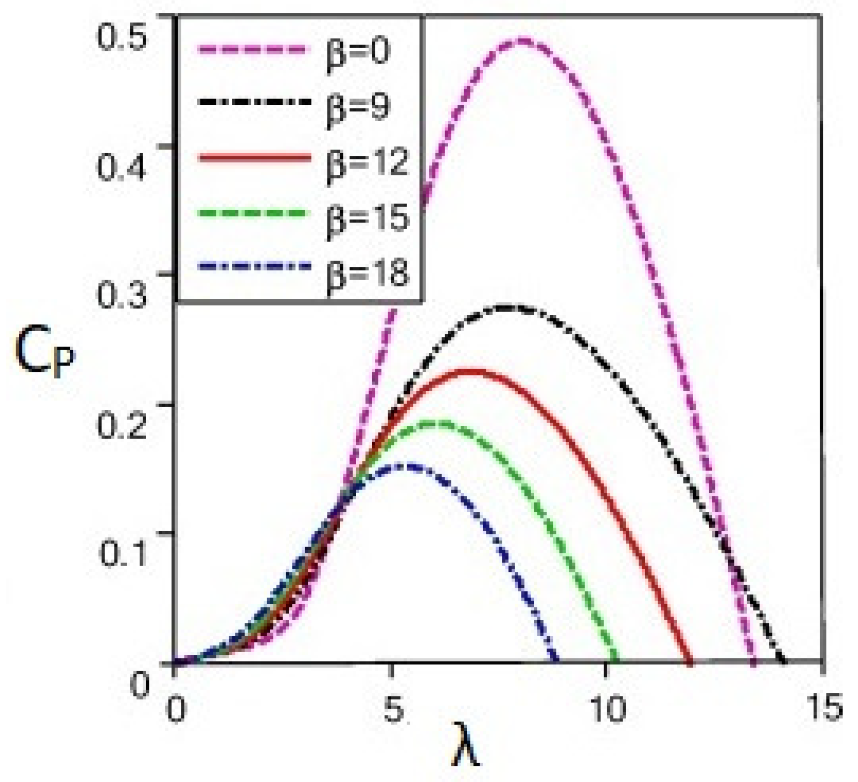
2.1. Aerodynamic Model

The aerodynamic equations for rotor power and torque are given by [30]:
P A   =   1 2 ρ π R 2 C p ( λ , β ) V w i n d 3
T A   =   P A ω r   =   1 2 ω r ρ π R 3 C T ( λ , β ) V w i n d 2
where ρ is the air density, R is the radius of the wind turbine, V w i n d is the wind speed, C p ( λ , β ) and C T ( λ , β ) represent the power and torque coefficients, respectively, β is the pitch angle, and λ is the tip-speed ratio. The tip-speed ratio is a function of the rotor speed, which can be represented as:
λ   =   R ω r V w i n d
The power coefficient is a function of both the pitch angle ( β ) and tip-speed ratio ( λ ) , as defined by the following expression:
C p ( λ , β )   =   0.5176 ( 116 λ j     0.4 β     5 ) e 21 λ j   +   0.0068 λ
1 λ j   =   1 λ   +   0.08 β     0.035 β 3   +   1
C p m a x   =   C p ( λ o p t , β )
The wind turbine can generate the maximum power provided that the power coefficient C p ( λ , β ) is maximum for any wind speed within the wide operation region of the turbine. The power coefficient can be maximized by maintaining the optimal value of the tip-speed ratio and fixed pitch angle. The relationship between C p ( λ , β ) and λ at different fixed values of β is illustrated in Figure 2. Therefore, the optimal reference speed applied to the WECS-PMSG is given by:
ω r _ o p t   =   λ o p t R V w i n d
The maximum power extracted by the WECS-PMSG under the optimal rotor speed thus can be represented as:
P A o p t   =   1 2 ρ π R 2 C p m a x ( λ o p t , β ) R ω r _ o p t λ o p t 3

2.2. PMSG Model

The dynamic model of the PMSG and the torque in the d-q coordinate system are formulated as [41]:
U d s   =   R s I d s   +   L d   +   d I d s d t     ω e L q I q s
U q s   =   R s I q s   +   L q   +   d I q s d t   +   ω e L d I d s   +   ω e Λ f
T e   =   3 2 p [ ( L d     L q ) I d s I q s   +   Λ f I q s ]
where I d s and I q s are the d and q axes’ stator currents, U d s and U q s are the stator voltages, L d and L q stand for inductance, R s denotes the stator resistance, Λ f represents the rotor flux, ω e   =   p ω r is the electrical speed, and T e indicates the electromagnetic torque. If L d   =   L q , Equation (11) will evolve as:
T e   =   3 2 p Λ f I q s

2.3. Shaft System Model

The dynamic model of the wind turbine shaft system is expressed as [30]:
d ω r d t   =   J 1 T a     J 1 T e     J 1 b w r
where b and J indicate the friction coefficient and the total mechanical inertia, respectively.

2.4. Overall Model

The overall model of the WECS-PMSG can be written as [30]:
x ˙ 1   =   a 1 T A   +   a 2 x 1   +   a 3 x 2   +   Δ 1
x ˙ 2   =   a 4 x 2   +   a 5 x 3 x 1   +   a 6 x 1 + g 1 U q s   +   Δ 2
x ˙ 3   =   a 7 x 3   +   a 8 x 1 x 2   +   g 2 U d s   +   Δ 3
where x 1   =   ω r , x 2   =   I q s , x 3   =   I d s , a 1   =   J 1 , a 2   =   3 2 p Λ f , a 3   =   J 1 b , a 4   =   R s L q , a 5   =   p L d L q , a 6   =   Λ f p , a 7   =   R s L d , and a 8   =   L q L d p .

3. Control of WECS-PMSG

The article aims to design a robust control algorithm that keeps operating the WECS-PMSG within the point of maximum power extraction. The control variables are y 1   =   x 1 and y 2   =   x 2 . By differentiating y 1 twice and y 2 once, the following equations are obtained:
y ¨ 1   =   f 1   +   g 1 u 1   +   Δ y 1
y ˙ 2   =   f 2   +   g 2 u 2   +   Δ y 2
where f 1   =   a 1 T ˙ A   +   a 2 x ˙ 1   +   a 3 [ a 4 x 2   +   a 5 x 3 x 1   +   a 6 x 1 ] , g 1   =   a 3 b 1 , f 2   =   a 7 x 3   +   a 8 x 1 x 2 , g 2   =   b 2 , Δ y 1   =   Δ ˙ 1   +   a 3 Δ 2 , and Δ y 2   =   Δ 3
Assumption A1.
The lumped disturbances are bounded, e.g.,
Δ y 1     M 11 Δ y 2     M 21
where M 11 and M 21 are the upper bounds of the disturbances and Δ y 1 and Δ y 2 are the net disturbances in the input–output dynamics of Equations (17) and (18).

3.1. Design of NFTSMC

In this section, NFTSMC is designed for y 1 and y 2 by assuming that the upper bounds of the lumped disturbances are known exactly.

3.1.1. Design of the NFTSMC for the Rotor Speed

If the tracking error between y 1 and ω r _ o p t is defined as:
e 1   =   y 1     ω r _ o p t e ˙ 1   =   y ˙ 1     ω ˙ r _ o p t e ¨ 1   =   y ¨ 1     ω ¨ r _ o p t   =   f 1   +   g 1 u 1   +   Δ y 1     ω ¨ r _ o p t
The NFTSMC surface is defined as [43]:
S 1   =   e 1   +   C 11 | e 1 | μ s i g n ( e 1 )   +   C 12 | e ˙ 1 | α s i g n ( e ˙ 1 )
where C 11 and C 12 are positive constants, 1   <   α   <   2 and μ   >   β . The following equation is derived from the time derivative of S 1 :
S ˙ 1   =   e ˙ 1   +   C 11 μ | e 1 | μ 1 e ˙ 1   +   C 12 α | e ˙ 1 | α 1 e ¨ 1   =   e ˙ 1   +   C 11 μ | e 1 | μ 1 e ˙ 1   +   C 12 α | e ˙ 1 | α 1 f 1   +   g 1 u 1   +   Δ y 1     ω ¨ r _ o p t
By recognizing that S ˙ 1   =   S 1   =   0 , the equivalent control input u 1 e q is derived as:
u 1 e q   =   g 1 1 f 1     1 C 12 α | e ˙ 1 | 2 α ( 1   +   μ C 11 | e 1 | μ 1 ) s i g n ( e ˙ 1 )
If the system dynamics are known precisely, the equivalent control law u 1 can make the states remain on (20). In order to meet the sliding condition in the presence of the lumped disturbance, the reaching law is given by the following equation:
u 1 r   =   g 1 1 [ M 11 s i g n ( S 1 )     M 12 S 1 ]
where M 11 and M 12 are constants. Thus, the overall control law is established by the following equation as:
u 1   =   u 1 e q   +   u 1 r   =   g 1 1 f 1 1 C 12 α | e ˙ 1 | 2 α ( 1   +   μ C 11 | e 1 | μ 1 ) s i g n ( e ˙ 1 ) M 11 s i g n ( S 1 )     M 12 S 1
Theorem 1.
Considering the output dynamics of Equation (17), if it is controlled with Equation (24), the state variables will converge to the surface of Equation (20).
Proof of Theorem 1.
Consider the following Lyapunov function candidate:
V 1   =   1 2 S 1 2
Taking the time derivative of V 1 and using Equations (21) and (24), the following equation is evolved:
V ˙ 1   =   S 1 S ˙ 1   =   C 12 α | e ˙ 1 | α 1 S 1 Δ y 1 M 11 | S 1 | M 12 S 1 2 C 12 α | e ˙ 1 | α 1 ( Δ y 1 M 11 ) | S 1 | M 12 S 1 2
The following equation is obtained by considering Assumption 1.
V ˙ 1     C 12 α | e ˙ 1 | α 1 M 12 S 1 2     0
From the definition of Lyapunov stability theory, the output y 1 asymptotically converges to the surface S 1   =   0 .

3.1.2. Design of the NFTSMC for the D-Component of the Stator Current

Consider the following tracking error between y 2 and I d s _ r e f :
e 2   =   y 2     I d s _ r e f e ˙ 2   =   y ˙ 2 I ˙ d s _ r e f   =   f 2   +   g 2 u 2   +   Δ y 2     I ˙ d s _ r e f
Since the relative degree of y 2 is one, the following NFTSMC surface is introduced.
S 2   =   e 2   +   C 2 | e ˙ 2 | α s i g n ( e ˙ 2 )
where C 2 is a positive constant. The time derivative of S 2 yields:
S ˙ 2   =   e ˙ 2   +   C 2 α | e ˙ 2 | α 1 e ¨ 2   =   e ˙ 2   +   C 2 α | e ˙ 2 | α 1 [ f ˙ 2   +   g 2 u ˙ 2   +   Δ ˙ y 2 I ¨ d s _ r e f ]
where f ˙ 2   =   f 2 x 1 x ˙ 1   +   f 2 x 2 x ˙ 2   +   f 2 x 3 x ˙ 3 . The equivalent control law is derived as:
u ˙ 2 e q   =   g 2 1 f ˙ 2 1 C 2 α | e ˙ 2 | 2 α   +   I ¨ d s _ r e f
The reaching law is designed as u ˙ 2 r   =   g 2 1 [ M 21 s i g n ( S 2 )   +   M 22 S 2 ] . The control law for Equation (18) is given by:
u 2   =   u 2 e q   +   u 2 r   =   0 t ( u ˙ 2 e q ( τ )   +   u ˙ 2 r ( τ ) ) d τ   =   g 2 1 0 t f ˙ 2 | e ˙ 2 | 2 α C 2 α   +   I ¨ d s _ r e f     M 21 s i g n ( S 2 )     M 22 S 2 d τ
Theorem 2.
Considering the output dynamics of Equation (18), if it is controlled with Equation (32), the state variables will converge to the surface as shown in Equation (29).
Proof of Theorem 2.
Consider the Lyapunov candidate as:
V 2 = 1 2 S 2 2
After differentiating V 2 with respect to time and using Equations (30) and (32), the following equation can be obtained:
V ˙ 2   =   S 2 S ˙ 2   =   C 2 | e ˙ 2 | α 1 S 2 Δ y 2     M 21 | S 2 |     M 22 S 2 2 C 2 α | e ˙ 2 | α 1 ( Δ y 2     M 21 ) | S 2 |     M 22 S 2 2
Based on Assumption A1, Equation (34) becomes:
V ˙ 2     C 2 α | e ˙ 2 | α 1 M 22 S 2 2     0

3.2. Design of ANFTSMC

In practical applications, it is difficult to precisely obtain the upper bounds of the system lumped disturbances. As such, we developed an adaptation scheme to estimate the upper bounds and suppress the lumped disturbances, which can improve the robustness of the control system.

3.2.1. Design of the ANFTSMC for the Rotor Speed

The control law of Equation (24) is modified as:
u 1   =   g 1 1 f 1 1 C 12 α | e ˙ 1 | 2 α ( 1   +   μ C 11 | e 1 | μ 1 ) s i g n ( e ˙ 1 ) M ^ 11 s i g n ( S 1 ) M ^ 12 S 1
where M ^ 11 and M ^ 12 are the estimates of M 11 and M 12 , respectively. The following adaptive rules update the gains:
M ^ ˙ 11   =   γ 11 | e ˙ 1 | α 1 | S 1 | M ^ ˙ 12   =   γ 12 | e ˙ 1 | α 1 S 1 2
where γ 11 and γ 12 are positive constants.
Remark 1.
The adaptation gains γ 11 and γ 12 are adjusted by trial and error and then kept constant when the desired responses are achieved.
The main results of the adaptive scheme can be expressed in the following theorem:
Theorem 3.
Considering that the upper bounds of the lumped disturbances of Equation (17) are unknown, if the NFTSMC surface is chosen as Equation (20), the adaptive controller is designed as Equation (36); then, the trajectory tracking error asymptotically converge to zero.
Proof of Theorem 3.
The Lyapunov function of Equation (25) is modified as follows:
V 1   =   1 2 S 1 2   +   1 2 γ 11 M ˜ 11 2   +   1 2 γ 12 M ˜ 12 2
where M ˜ 11   =   M 11 M ^ 11 , M ˜ 12   =   M 12     M ^ 12 . Calculating the time derivative of Equation (38) yields:
V ˙ 1   =   S 1 S ˙ 1     M ˜ 11 M ^ ˙ 11     M ˜ 12 M ^ ˙ 12
Based on Equations (21) and (36), the following equation can be obtained:
V ˙ 1   =   C 12 α | e ˙ 1 | α 1 S 1 Δ y 1     M ^ 11 | S 1 |     M ^ 12 S 1 2     M ˜ 11 M ^ ˙ 11 M ˜ 12 M ^ ˙ 12 C 12 α | e ˙ 1 | α 1 ( Δ y 1 M 11 ) | S 1 |     M 12 S 1 2   +   M ˜ 11 | e ˙ 1 | α 1 | S 1 |     M ^ ˙ 11   +   M ˜ 12 | e ˙ 1 | α 1 S 1 2     M ^ ˙ 12
Using Equation (38) and Assumption (A1), Equation (40) can be represented as:
V ˙ 1     C 12 α | e ˙ 1 | α 1 M 12 S 1 2     0

3.2.2. Design of the ANFTSMC for the D-Component of the Stator Current

The adaptive control input for the y 2 dynamics is written as:
u 2   =   u 2 e q   +   u 2 r   =   0 t ( u ˙ 2 e q ( τ )   +   u ˙ 2 r ( τ ) ) d τ   =   g 2 1 0 t f ˙ 2 | e ˙ 2 | 2 α C 2 α   +   I ¨ d s _ r e f M ^ 21 s i g n ( S 2 )     M ^ 22 S 2 d τ
where M ^ 21 and M ^ 22 are the estimates of M 21 and M 22 , respectively. The following adaptive laws update the gains:
M ^ ˙ 21   =   γ 21 | e ˙ 2 | α 1 | S 2 | M ^ ˙ 22   =   γ 22 | e ˙ 2 | α 1 S 2 2
where γ 21 and γ 22 are positive constants.
Remark 2.
The adaptation gains γ 21 and γ 22 are adjusted on a systematical trial and error basis; then, they are kept constant when the desired responses are achieved.
The main results of the ANFTSMC for the y 2 dynamics are summarized in the following theorem:
Theorem 4.
Suppose the information about the upper bounds of the lumped disturbances of Equation (18) is unavailable if the NFTSMC surface is selected as Equation (29); the adaptive controller is developed as (42), and the trajectory tracking error asymptotically converges to zero.
Proof of Theorem 4.
Equation (33) can be modified as follows:
V 2   =   1 2 S 2 2   +   1 2 γ 21 M ˜ 21 2   +   1 2 γ 22 M ˜ 22 2
where M ˜ 21   =   M 21 M ^ 21 , M ˜ 22   =   M 22     M ^ 22 . Computing the time derivative of Equation (44) gives:
V ˙ 2   =   S 2 S ˙ 2 M ˜ 21 M ^ ˙ 21 M ˜ 22 M ^ ˙ 22
The following relationship can be obtained after substituting Equations (30) and (42) into Equation (45):
V ˙ 2   =   C 2 | e ˙ 2 | α 1 S 2 Δ y 2     M ^ 21 | S 2 | M ^ 22 S 2 2 M ˜ 21 M ^ ˙ 21 M ˜ 22 M ^ ˙ 22 C 2 α | e ˙ 2 | α 1 ( Δ y 2 M 21 ) | S 2 | M 22 S 2 2   +   M ˜ 21 | S 1 | M ^ ˙ 21 γ 21   +   M ˜ 22 S 2 2     M ^ ˙ 22 γ 22
Equation (46) can be modified using Equation (43) and Assumption (1) as:
V ˙ 1 C 2 α | e ˙ 2 | α 1 M 22 S 2 2 0
Remark 3.
The chattering issue due to the discontinuous control component (sign(.) function) is solved by replacing it with the tanh(.) function [45].

4. Simulation Results and Discussions

The simulation was performed in the MATLAB/SIMULINK 2020 Platform using a PC with an Intel(R) Core(TM) i7-10510U CPU @ 2.3 GHz and 8 GB RAM. The parameters of the WECS-PMSG were taken from [30]. The PMSG parametric variations of 40 % were also taken into consideration in the simulation. The parameters of the proposed controller are given in Table 1. The initial conditions of the PMSG states and the adaptive laws were set as 0.01. To highlight the effectiveness of ANFTSMC in achieving the MPPT of the WECS-PMSG, a comparative study was executed with some existing control techniques such as FLC [27], passivity-based SMC (PSMC) [30], and adaptive STSMC (ASTSMC) [39] under four cases, e.g., the step change of the wind speed, the short-term random variation of the wind speed, the long-term random variation of the wind speed, and the real wind speed profile.

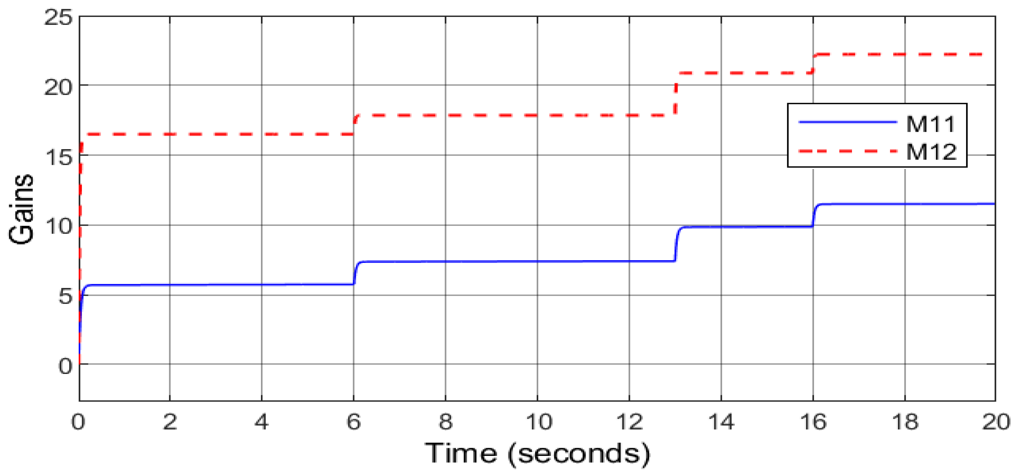
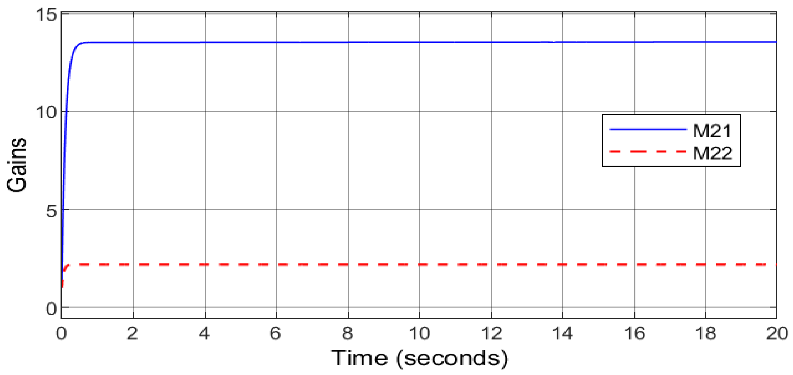
4.1. Step Change of the Wind Speed

In this case, it was assumed that the wind speed profile is a sequence of four-step changes, as shown in Figure 3. The performances of different controllers to achieve the MPPT of the WECS-PMSG are presented in Figure 4, Figure 5, Figure 6 and Figure 7. Figure 4 shows that ANFTSMC was able to track the optimal rotor speed with greater accuracy than ASTSMC, PSMC, and FLC. The evolution of the maximum power coefficient is shown in Figure 5. From this figure, it can be seen that ANFTSMC was able to restore the power coefficient to the required value at a faster rate than ASTSMC, PSMC, and FLC whenever the wind speed in Figure 3 changed. The tracking responses of the optimal power under various control methods are depicted in Figure 6. From this figure, it is clear that ANFTSMC was able to follow the optimal power with greater accuracy than ASTSMC, PSMC, and FLC. The estimated parameters of the rotor speed and the d-component of the stator current controllers are presented in Figure 7 and Figure 8, respectively. From these figures, it can be observed that the FLC controller gave the worst control performances in the presence of parametric uncertainties. Due to the robustness of PSMC, ASTSMC, and ANFTSMC, the uncertainties in the WECS-PMSG were mitigated, and better control performances were obtained. However, the WECS-PMSG under the proposed ANFTSMC attained the MPPT in a shorter time than FLC, ASTSMC, and FLC. Therefore, the effectiveness of the proposed ANFTSMC strategy under the step change of the wind speed was justified.

4.2. Random Variation of the Wind Speed

To further illustrate the effectiveness of the proposed ANFTSMC, a random wind speed profile with a mean value of 11 m/s, as shown in Figure 9, was applied to the WECS-PMSG. The control efforts of the four controllers are depicted in Figure 10, Figure 11 and Figure 12. The rotor speed and the optimal rotor speed are presented in Figure 10. It can be observed from the figure that ANFTSMC showed the best optimal rotor speed tracking performance. Figure 11 illustrates the maximum power coefficient signals of the four control methods. Due to the random nature of the wind, the power coefficients under the control approaches fluctuated near the required maximum power coefficient. However, under the action of ANFTSMC, the power coefficient was closer to the required value than ASTSMC, PSMC, and FLC. The optimal power harnessed from the random wind is shown in Figure 12. It can be seen that ANFTSMC followed the fluctuating optimal wind power with more accuracy than ASTSMC, PSMC, and FLC. These figures show that FLC did not satisfactorily reach the MPPT of the WECS-PMSG as FLC requires an exact system modeling and is sensitive to the model uncertainties. On the other hand, ANFTSMC, ASTSMC, and PSMC were robust to the WECS-PMSG parametric uncertainties, and as such, they achieved the MPPT. Nevertheless, ANFTSMC exhibited more effectiveness as its responses were much closer to the MPPT under the random wind speed. Therefore, the efficacy of the proposed ANFTSMC strategy under the random variation of the wind speed was also justified.

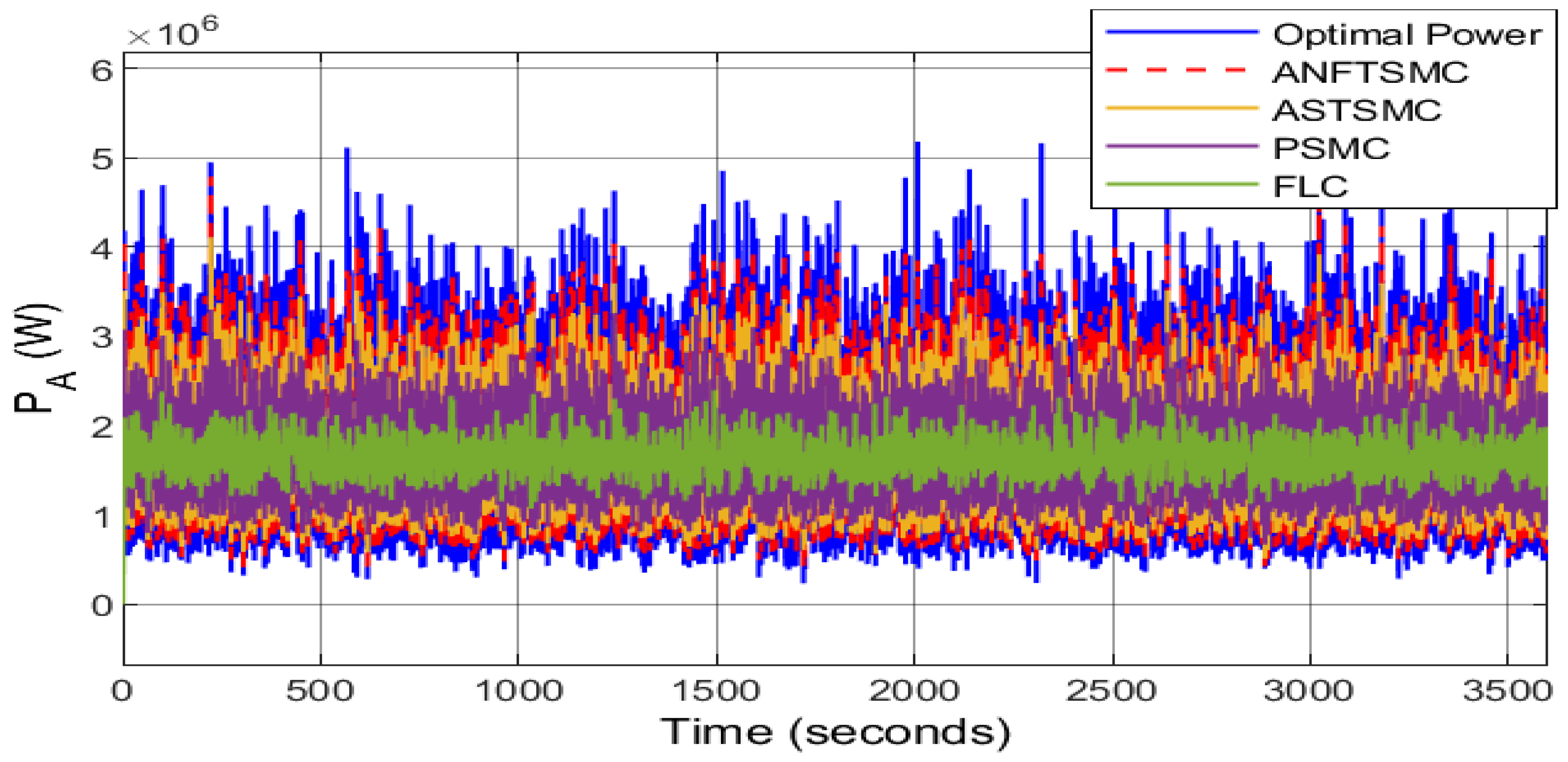
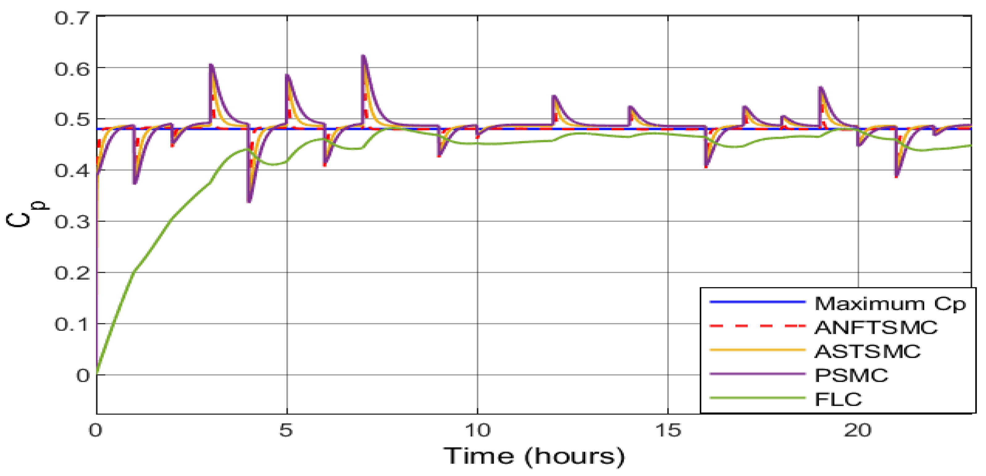
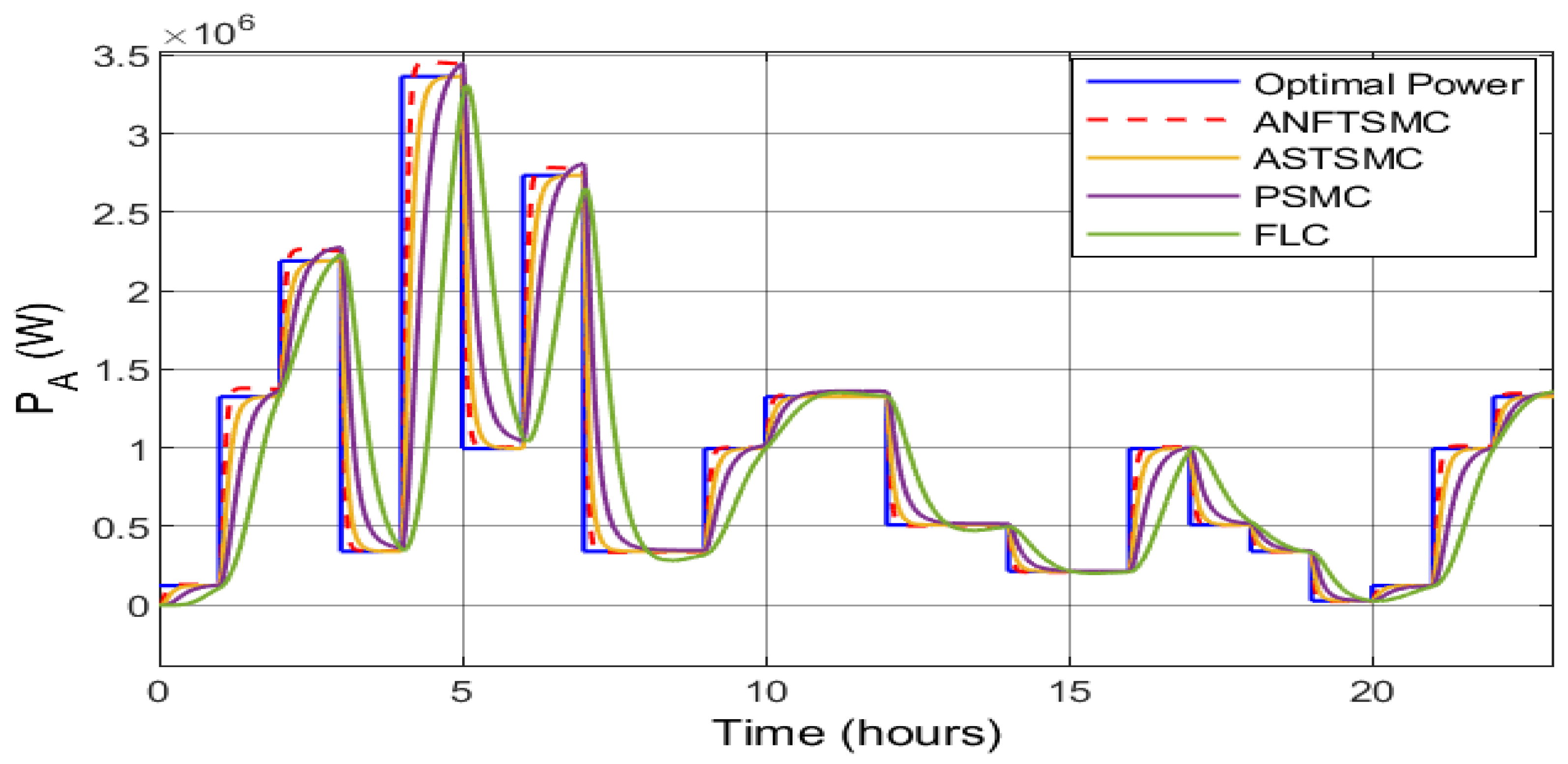
4.3. Long-Term Random Variation of the Wind Speed

The random wind speed profile in Figure 9 was extended for 1 h (3600 s), as shown in Figure 13, in order to highlight the performance of ANFTSMC over other strategies. From Figure 14, it is clear that the rotor speed was varied between 3.45 rad/s and 1.27 rad/s due to the random variation of the wind speed, and the ANFTSMC strategy tracked the variation more precisely (closer to the peaks and troughs of the rotor speed) than other strategies. The performance of the FLC strategy was the worst amongst the compared strategies as the responses were far away from the peak and trough values of the rotor speed. PMSC performed better than FLC, and ASTSMC performed better than PMSC. The power coefficient was varied rapidly with the rapid variation of the wind speed, as shown in Figure 15. The optimal power harnessed by the WECS-PMSG under the action of four different control approaches over a period of 1 h is depicted in Figure 16. This figure shows that ANFTSMC was able to follow the peaks and troughs of the optimal power with greater accuracy than ASTSMC, PSMC, and FLC. Therefore, the efficacy of the proposed ANFTSMC strategy under the long-term random variation of the wind speed was also justified.

4.4. Historical Wind Speed Profile

The wind speed profile of Montreal on 31 March 2017 from 0:00 to 23:00 was applied to the WECS-PMSG to examine the performance of the proposed ANFTSMC on a real wind speed profile. Figure 17 depicts the 24 h wind speed profile of Montreal as collected from [46]. It can be seen from Figure 18 that the rotor speed varied between 0.61 rad/s and 2.87 rad/s due to the wind speed variation at the Montreal Weather Station. The ANFTSMC strategy tracked the variation more precisely (closer to the peaks and troughs of the rotor speed) than the other strategies. Similar to the previous cases, the responses of the FLC strategy were far away from the peak and trough values of the rotor speed. On the contrary, PMSC performed better than FLC, and ASTSMC performed better than PMSC. Figure 19 depicts the power coefficient variation of the extracted power. Figure 20 illustrates the optimal power harnessed by the WECS-PMSG for the real wind speed profile over a period of 24 h. It is observed from both Figure 19 and Figure 20 that ANFTSMC maintained its superiority over other strategies. Therefore, the efficacy of the proposed strategy under the historical wind speed profile of Montreal was also justified.

5. Conclusions

This paper presented an ANFTSMC strategy for the WECS-PSMG with model uncertainties to capture the maximum power. The proposed approach ensured singularity avoidance, robustness against unknown WECS-PSMG dynamic uncertainties, and a fast convergence rate to achieve the MPPT. Four case studies (step change of the wind speed, short-time random variation of the wind speed, long-term random variation of the wind speed, and a real wind speed profile) were considered to evaluate the efficient operation of the proposed strategy. In each case, the proposed method outperformed other techniques, including FLC, PSMC, and ASTSMC. As extensions of this work, a laboratory-scale experimental setup, very short-term wind forecasts, measurement uncertainty, and a system with energy storage can be considered.

Author Contributions

Conceptualization, M.M. and M.S.; methodology, M.M.; software, M.M.; validation, M.M., M.S., A.T.A.-A. and F.S.A.-I.; formal analysis, M.M., M.S. and A.T.A.-A.; investigation, M.M., M.S., A.T.A.-A. and F.S.A.-I.; resources, M.M. and M.S.; data curation, M.M., M.S. and F.S.A.-I.; writing—original draft preparation, M.M.; writing—review and editing, M.S., A.T.A.-A. and F.S.A.-I.; visualization, M.M., M.S., A.T.A.-A. and F.S.A.-I.; supervision, M.S., A.T.A.-A. and F.S.A.-I.; project administration, M.S., A.T.A.-A. and F.S.A.-I.; funding acquisition, A.T.A.-A.; All authors have read and agreed to the published version of the manuscript.

Funding

King Fahd University of Petroleum & Minerals (KFUPM): DF201006.

Institutional Review Board Statement

Not applicable.

Informed Consent Statement

Not applicable.

Data Availability Statement

Data will be made available on request.

Acknowledgments

The authors would like to acknowledge the support provided by the Deanship of Scientific Research (DSR) and Interdisciplinary Research Center for Smart Mobility and Logistics, King Fahd University of Petroleum & Minerals (KFUPM), for funding this work through Project No. DF201006.

Conflicts of Interest

The authors declare no conflict of interest.

References

  1. Mínaz, M.R.; Akcan, E. An Effective Method for Detection of Demagnetization Fault in Axial Flux Coreless PMSG with Texture-Based Analysis. IEEE Access 2021, 9, 17438–17449. [Google Scholar] [CrossRef]
  2. Maaruf, M.; Khan, K.A.; Khalid, M. Integrated Power Management and Nonlinear-Control for Hybrid Renewable Microgrid. In Proceedings of the 2021 IEEE Green Technologies Conference (GreenTech), Denver, CO, USA, 7–11 April 2021; pp. 176–180. [Google Scholar] [CrossRef]
  3. Kaldellis, J.; Apostolou, D. Life cycle energy and carbon footprint of offshore wind energy. Comparison with onshore counterpart. Renew. Energy 2017, 108, 72–84. [Google Scholar] [CrossRef]
  4. Ahmed, S.D.; Al-Ismail, F.S.; Shafiullah, M.; Al-Sulaiman, F.A.; El-Amin, I.M. Grid integration challenges of wind energy: A review. IEEE Access 2020, 8, 10857–10878. [Google Scholar] [CrossRef]
  5. Feng, S.; Wang, K.; Lei, J.; Tang, Y. Influences of DC bus voltage dynamics in modulation algorithm on power oscillations in PMSG-based wind farms. Int. J. Electr. Power Energy Syst. 2021, 124, 106387. [Google Scholar] [CrossRef]
  6. Shanmugam, L.; Joo, Y.H. Stabilization of permanent magnet synchronous generator-based wind turbine system via fuzzy-based sampled-data control approach. Inf. Sci. 2021, 559, 270–285. [Google Scholar] [CrossRef]
  7. Zribi, M.; Alrifai, M.; Rayan, M. Sliding Mode Control of a Variable- Speed Wind Energy Conversion System Using a Squirrel Cage Induction Generator. Energies 2017, 10, 604. [Google Scholar] [CrossRef] [Green Version]
  8. Tripathi, S.; Tiwari, A.; Singh, D. Grid-integrated permanent magnet synchronous generator based wind energy conversion systems: A technology review. Renew. Sustain. Energy Rev. 2015, 51, 1288–1305. [Google Scholar] [CrossRef]
  9. Bonfiglio, A.; Delfino, F.; Gonzalez-Longatt, F.; Procopio, R. Steady-state assessments of PMSGs in wind generating units. Int. J. Electr. Power Energy Syst. 2017, 90, 87–93. [Google Scholar] [CrossRef] [Green Version]
  10. Yang, B.; Yu, T.; Shu, H.; Zhang, X.; Qu, K.; Jiang, L. Democratic joint operations algorithm for optimal power extraction of PMSG based wind energy conversion system. Energy Convers. Manag. 2018, 159, 312–326. [Google Scholar] [CrossRef]
  11. Abd El Hamied, M.A.; Amary, N.H.E. Permanent Magnet Synchronous Generator Stability Analysis and Control. Procedia Comput. Sci. 2016, 95, 507–515. [Google Scholar] [CrossRef] [Green Version]
  12. Zarei, M.E.; Ramirez, D.; Prodanovic, M.; Medrano Arana, G. Model Predictive Control for PMSG-based Wind Turbines with Overmodulation and Adjustable Dynamic Response Time. IEEE Trans. Ind. Electron. 2021, 69, 1573–1585. [Google Scholar] [CrossRef]
  13. Maaruf, M.; Ferik, S.E.; Mahmoud, M.S. Integral Sliding Mode Control With Power Exponential Reaching Law for DFIG. In Proceedings of the 2020 17th International Multi-Conference on Systems, Signals Devices (SSD), Monastir, Tunisia, 20–23 July 2020; pp. 1122–1127. [Google Scholar] [CrossRef]
  14. Rhaili, S.; Abbou, A.; Ziouh, A.; Elidrissi, R. Comparative study between PI and FUZZY logic controller in vector controlled five-phase PMSG based variable-speed wind turbine. In Proceedings of the 2018 IEEE 12th International Conference on Compatibility, Power Electronics and Power Engineering (CPE-POWERENG 2018), Doha, Qatar, 10–12 April 2018; pp. 1–6. [Google Scholar]
  15. Giraldo, E.; Garces, A. An Adaptive Control Strategy for a Wind Energy Conversion System Based on PWM-CSC and PMSG. IEEE Trans. Power Syst. 2014, 29, 1446–1453. [Google Scholar] [CrossRef]
  16. Shafiullah, M.; Abido, M.A.; Coelho, L.S. Design of robust PSS in multimachine power systems using backtracking search algorithm. In Proceedings of the 2015 18th International Conference on Intelligent System Application to Power Systems (ISAP), Porto, Portugal, 11–16 September 2015; IEEE: Piscataway, NJ, USA, 2015; pp. 1–6. [Google Scholar]
  17. Saad, N.H.; El-Sattar, A.A.; Marei, M.E. Improved bacterial foraging optimization for grid connected wind energy conversion system based PMSG with matrix converter. Ain Shams Eng. J. 2018, 9, 2183–2193. [Google Scholar] [CrossRef]
  18. Alam, M.S.; Shafiullah, M.; Hossain, M.I.; Hasan, M.N. Enhancement of power system damping employing TCSC with genetic algorithm based controller design. In Proceedings of the 2015 International Conference on Electrical Engineering and Information Communication Technology (ICEEICT), Savar, Bangladesh, 21–23 May 2015; IEEE: Piscataway, NJ, USA, 2015; pp. 1–5. [Google Scholar]
  19. Haridy, A.L.; Abdelbasset, A.A.M.; Hemeida, M. Optimum Controller Design Using the Ant Lion Optimizer for PMSG Driven by Wind Energy. J. Electr. Eng. Technol. 2021, 16, 367–380. [Google Scholar] [CrossRef]
  20. Shafiullah, M.; Rana, M.J.; Coelho, L.S.; Abido, M.A. Power system stability enhancement by designing optimal PSS employing backtracking search algorithm. In Proceedings of the 2017 6th International Conference on Clean Electrical Power (ICCEP), Santa Margherita Ligure, Italy, 27–29 June 2017; IEEE: Piscataway, NJ, USA, 2017; pp. 712–719. [Google Scholar]
  21. Shafiullah, M.; Rana, M.J.; Shahriar, M.S.; Zahir, M.H. Low-frequency oscillation damping in the electric network through the optimal design of UPFC coordinated PSS employing MGGP. Measurement 2019, 138, 118–131. [Google Scholar]
  22. Qais, M.H.; Hasanien, H.M.; Alghuwainem, S.; Elgendy, M.A. Output Power Smoothing of Grid-Tied PMSG-Based Variable Speed Wind Turbine Using Optimal Controlled SMES. In Proceedings of the 2019 54th International Universities Power Engineering Conference (UPEC), Bucharest, Romania, 3–6 September 2019; pp. 1–6. [Google Scholar]
  23. Qais, M.H.; Hasanien, H.M.; Alghuwainem, S. A novel LMSRE-based adaptive PI control scheme for grid-integrated PMSG-based variable-speed wind turbine. Int. J. Electr. Power Energy Syst. 2021, 125, 106505. [Google Scholar] [CrossRef]
  24. Shafiullah, M.; Rana, M.J.; Shahriar, M.S.; Al-Sulaiman, F.A.; Ahmed, S.D.; Ali, A. Extreme learning machine for real-time damping of LFO in power system networks. Electr. Eng. 2021, 103, 279–292. [Google Scholar] [CrossRef]
  25. Mahmoud, M.S.; Maaruf, M.; El-Ferik, S. Neuro-adaptive output feedback control of the continuous polymerization reactor subjected to parametric uncertainties and external disturbances. ISA Trans. 2021, 112, 1–11. [Google Scholar] [CrossRef]
  26. Mahmud, M.A.; Roy, T.K.; Littras, K.; Islam, S.N.; Amanullah Oo, M.T. Nonlinear Partial Feedback Linearizing Controller Design for PMSG-Based Wind Farms to Enhance LVRT Capabilities. In Proceedings of the 2018 IEEE International Conference on Power Electronics, Drives and Energy Systems (PEDES), Chennai, India, 18–21 December 2018; pp. 1–6. [Google Scholar]
  27. Soufi, Y.; Kahla, S.; Bechouat, M. Feedback linearization control based particle swarm optimization for maximum power point tracking of wind turbine equipped by PMSG connected to the grid. Int. J. Hydrogen Energy 2016, 41, 20950–20955. [Google Scholar] [CrossRef]
  28. El Mourabit, Y.; Derouich, A.; El Ghzizal, A.; El Ouanjli, N.; Zamzoum, O. Nonlinear backstepping control for PMSG wind turbine used on the real wind profile of the Dakhla-Morocco city. Int. Trans. Electr. Energy Syst. 2020, 30, e12297. [Google Scholar] [CrossRef]
  29. Saidi, Y.; Mezouar, A.; Miloud, Y.; Kerrouche, K.D.E.; Brahmi, B.; Benmahdjoub, M.A. Advanced non-linear backstepping control design for variable speed wind turbine power maximization based on tip-speed-ratio approach during partial load operation. Int. J. Dynam. Control 2020, 30, e12297. [Google Scholar] [CrossRef]
  30. Yang, B.; Yu, T.; Shu, H.; Zhang, Y.; Chen, J.; Sang, Y.; Jiang, L. Passivity-based sliding-mode control design for optimal power extraction of a PMSG based variable speed wind turbine. Renew. Energy 2018, 119, 577–589. [Google Scholar] [CrossRef]
  31. Xiong, L.; Li, P.; Ma, M.; Wang, Z.; Wang, J. Output power quality enhancement of PMSG with fractional order sliding mode control. Int. J. Electr. Power Energy Syst. 2020, 115, 105402. [Google Scholar] [CrossRef]
  32. Sami, I.; Ullah, S.; Ullah, N.; Ro, J.S. Sensorless fractional order composite sliding mode control design for wind generation system. ISA Trans. 2021, 111, 275–289. [Google Scholar] [CrossRef]
  33. Dursun, E.H.; Kulaksiz, A.A. Second-order sliding mode voltage-regulator for improving MPPT efficiency of PMSG-based WECS. Int. J. Electr. Power Energy Syst. 2020, 121, 106149. [Google Scholar] [CrossRef]
  34. Nasiri, M.; Mobayen, S.; Zhu, Q.M. Super-Twisting Sliding Mode Control for Gearless PMSG-Based Wind Turbine. Complexity 2019, 2019, 6141607. [Google Scholar] [CrossRef]
  35. Yazıcı, İ.; Yaylacı, E.K. Discrete-time integral terminal sliding mode based maximum power point controller for the PMSG-based wind energy system. IET Power Electron. 2019, 12, 3688–3696. [Google Scholar] [CrossRef]
  36. Dursun, E.H.; Kulaksiz, A.A. Second-Order Fast Terminal Sliding Mode Control for MPPT of PMSG-based Wind Energy Conversion System. Elektron. Elektrotechnika 2020, 26, 39–45. [Google Scholar] [CrossRef]
  37. Sami, I.; Ullah, S.; Ali, Z.; Ullah, N.; Ro, J.S. A Super Twisting Fractional Order Terminal Sliding Mode Control for DFIG-Based Wind Energy Conversion System. Energies 2020, 13, 2158. [Google Scholar] [CrossRef]
  38. Kord, H.; Barakati, S.M. Design an adaptive sliding mode controller for an advanced hybrid energy storage system in a wind dominated RAPS system based on PMSG. Sustain. Energy Grids Netw. 2020, 21, 100310. [Google Scholar] [CrossRef]
  39. Tang, Y.; Zhang, Y.; Hasankhani, A.; VanZwieten, J. Adaptive Super-Twisting Sliding Mode Control for Ocean Current Turbine-Driven Permanent Magnet Synchronous Generator. In Proceedings of the 2020 American Control Conference (ACC), Denver, CO, USA, 1–3 July 2020; pp. 211–217. [Google Scholar]
  40. Sun, K.; Li, D.; Zheng, B. Adaptive Global Fast Terminal Sliding Mode Control for MPPT of Direct-driven PMSG. In Proceedings of the 2018 13th World Congress on Intelligent Control and Automation (WCICA), Changsha, China, 4–8 July 2018; pp. 1658–1663. [Google Scholar]
  41. Wang, J.; Bo, D.; Ma, X.; Zhang, Y.; Li, Z.; Miao, Q. Adaptive backstepping control for a permanent magnet synchronous generator wind energy conversion system. Int. J. Hydrogen Energy 2019, 44, 3240–3249. [Google Scholar] [CrossRef]
  42. Wang, J.; Bo, D. Adaptive fixed-time sensorless maximum power point tracking control scheme for DFIG wind energy conversion system. Int. J. Electr. Power Energy Syst. 2022, 135, 107424, in press. [Google Scholar] [CrossRef]
  43. Mahmoud, M.S.; Maaruf, M. Robust Adaptive Multilevel Control of a Quadrotor. IEEE Access 2020, 8, 167684–167692. [Google Scholar] [CrossRef]
  44. Yang, L.; Yang, J. Nonsingular fast terminal sliding-mode control for nonlinear dynamical systems. Int. J. Robust Nonlinear Control 2011, 21, 1865–1879. [Google Scholar] [CrossRef]
  45. Labbadi, M.; Cherkaoui, M. Robust adaptive backstepping fast terminal sliding mode controller for uncertain quadrotor UAV. Aerosp. Sci. Technol. 2019, 93, 105306. [Google Scholar] [CrossRef]
  46. Beniaguev, D. Historical Hourly Weather Data 2012–2017. Available online: https://www.kaggle.com/selfishgene/historical-hourly-weather-data (accessed on 31 October 2021).
Figure 1. The structure of the PMSG wind turbine system.
Sustainability 13 13427 g001
Figure 2. Power coefficient and tip-speed ratio ( C p λ ) relationship at different pitch angles.
Sustainability 13 13427 g002
Figure 3. Step change of wind speed profile for the first case study.
Sustainability 13 13427 g003
Figure 4. Tracking performance of the rotor speed under different control approaches for the first case study.
Sustainability 13 13427 g004
Figure 5. Power coefficient of the extracted power from the wind under different control approaches for the first case study.
Sustainability 13 13427 g005
Figure 6. Extracted power from the wind under different control approaches for the first case study.
Sustainability 13 13427 g006
Figure 7. Adaptive parameters of the rotor speed controller for the first case study.
Sustainability 13 13427 g007
Figure 8. Adaptive parameters of the d-component of the rotor current controller for the first case study.
Sustainability 13 13427 g008
Figure 9. Random wind speed profile for the second case study.
Sustainability 13 13427 g009
Figure 10. Tracking performance of the rotor speed under different control approaches for the second case study.
Sustainability 13 13427 g010
Figure 11. Power coefficient of the extracted power from the wind under different control approaches for the second case study.
Sustainability 13 13427 g011
Figure 12. Extracted power from the wind under different control approaches for the second case study.
Sustainability 13 13427 g012
Figure 13. Random wind speed profile for the third case study.
Sustainability 13 13427 g013
Figure 14. Tracking performance of the rotor speed under different control approaches for the third case study.
Sustainability 13 13427 g014
Figure 15. Power coefficient of the extracted power from the wind under different control approaches for the third case study.
Sustainability 13 13427 g015
Figure 16. Extracted power from the wind under different control approaches for the third case study.
Sustainability 13 13427 g016
Figure 17. Montreal 24 h wind speed profile on 31 March 2017 for the fourth case study.
Sustainability 13 13427 g017
Figure 18. Tracking performance of the rotor speed under different control approaches for the fourth case study.
Sustainability 13 13427 g018
Figure 19. Power coefficient of the extracted power from the wind under different control approaches for the fourth case study.
Sustainability 13 13427 g019
Figure 20. Extracted power from the wind under different control approaches for the fourth case study.
Sustainability 13 13427 g020
Table 1. Controller parameters.
ParametersValues
α , β 3/2,  3
C 11 , C 12 , C 21 , C 22 1, 1, 1, 1
γ 11 , γ 12 , γ 21 , γ 22 1, 0.04, 10, 15
Publisher’s Note: MDPI stays neutral with regard to jurisdictional claims in published maps and institutional affiliations.

