1. Introduction
With the rapid global increase in urbanization, the development of urban underground spaces has become essential for improving cities with regard to the economy, society, infrastructure, and environment. Urban underground spaces, which are used for transportation infrastructure (e.g., roads and parking lots), commercial facilities, and public facilities, allow efficient land utilization in places where the population density is rapidly increasing. Additionally, they significantly contribute to urban regeneration and sustainability (e.g., the preservation of old towns and cultural heritage, conservation of the aboveground environment, improvement of old facilities, undergrounding of unpleasant facilities, etc.) [
1]. Recently, underground space excavation for mining underground water and developing hot springs has also been actively carried out [
2]. However, the development of underground spaces entails high initial costs and can cause permanent deformation and pollution underground. Ironically, the development of underground spaces can enhance the sustainability of aboveground cities, while the underground spaces become a non-renewable resource. Therefore, it is necessary to devise a detailed strategy based on three-dimensional planning, prioritizing services, studying future functions, and spatial interrelations, before developing urban underground spaces [
3]. It is challenging to promote the development of urban underground spaces in cities wherein underground spaces were not included in the existing urban planning or in conventional metropolises that have already developed high-density underground spaces. Nevertheless, underground space utilization is the most efficient way to provide various opportunities for the regeneration of existing cities by efficient land use, reduction of traffic congestion, and eco-friendly development [
4].
One of the main factors hindering urban regeneration and sustainability is old buildings. Old buildings not only affect the aesthetics of cities but also entail the inefficient use of space and are often environmentally harmful. According to a 2018 press release from the Ministry of Land, Infrastructure and Transport of the Korean government, buildings over 10 years old (residential, industrial, etc.) accounted for more than 75% of all buildings in Korea. The ratio of buildings over 30 years old was approximately 36.5% [
5]. It is common for old buildings to be reconstructed after demolition for urban regeneration. However, as cities have become denser, it has become practically impossible to reconstruct an entire old building, owing to high demolition costs, environmental pollution, civil complaints, etc. In addition, as the number of high-rise buildings has increased since the 1980s, redevelopment projects involving the reconstruction of buildings in urban areas are becoming difficult. Most importantly, during the development of a site or underground space around an old building, safety issues such as cracking or collapse may occur in the old building owing to vibration and displacement. Moreover, ground settlement can also significantly affect the stability of surrounding facilities. Therefore, studies on empirical formulas which can predict ground settlement according to various ground and field conditions during ground excavation have been actively conducted [
6].
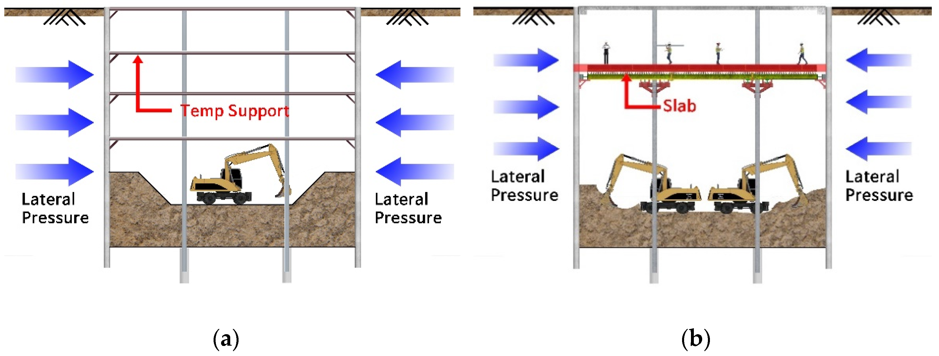
Consequently, both the utilization of underground spaces and the improvement of old buildings must be achieved for the regeneration and sustainability of conventional metropolises. One solution is to extend the underground space below an old building while not demolishing the superstructures (i.e., existing structures), which is called the floating and underground extension method. In this method, temporary facilities are first installed underground to support superstructures. Then, designed underground structures are constructed after underground space is excavated. Here, the method of excavating underground space at once and constructing underground structures from the lowest floor is called the bottom-up method. On the contrary, in the top-down method, underground structures are constructed from the first basement level according to the excavation steps. After underground structures are constructed, temporary facilities installed to support superstructures are usually demolished.
The floating and underground extension method has been widely adopted for developing underground spaces for large-scale facilities. To construct a new subway line while operating the Nagoya Station in Japan, superstructures were supported by installing temporary piles and underground slurry walls. Then, underground facilities were constructed using the top-down method. Used temporary piles were utilized as permanent foundations to reduce the construction costs and the amount of waste [
7]. Shanghai-Century-Avenue-Transit-Center (SCATC) conducted a project to integrate existing and new subway stations by extending an underground space. Before dismantling existing structures, an anti-upheaval system was installed to control the displacement of the structures and the ground. Additionally, the optimal construction process was selected through numerical simulations [
8]. Similarly, the floating and underground extension method was used to install a new subway line under the existing subway line in Seoul. Before the underground space was excavated, the stability of superstructures was ensured by installing temporary girders and piles. The temporary facilities were designed through three-dimensional numerical simulations [
9]. In addition to the subway line, the underground space of the four-story Seoul City Hall, a cultural building, was developed via the floating and underground extension method. After piles were constructed, bracings were installed to prevent the piles from buckling during underground space excavation. Then, underground facilities were constructed using the bottom-up method, and the temporary facilities were dismantled [
10]. Furthermore, Shin evaluated the stability of the underground complex of the Hankuk University of Foreign Studies, which was constructed via the floating and underground extension method, during the construction period [
11]. As such, the floating and underground extension method has been widely employed as the most effective way to develop or extend underground spaces of existing old buildings, buildings in use, cultural properties, etc., without demolishing superstructures. Recently, the number of cases involving the application of the floating and underground extension method to the seismic reinforcement or foundation reinforcement of existing buildings has increased [
12,
13].
Several studies were also conducted to analyze the economic feasibility and constructability of the floating and underground extension method depending on the types of temporary facilities and the construction sequence. Choi proposed a method of supporting superstructures by installing truss structures instead of conventional temporary facilities such as underground slurry walls and piles [
14]. Lee compared construction methods according to the ways in which superstructure loads are transmitted to the underground space [
15]. It was concluded that the appropriate method may depend on the existing superstructure and underground extension sizes. Seo et al. analyzed the constructability of the bottom-up and top-down methods [
16]. Constructing double beams on girders in the middle step of the top-down method was found to be superior with regard to constructability and the economic aspect.
The key problem is that sufficient space is needed to operate equipment for installing temporary facilities to adopt the floating and underground extension method. Therefore, it is challenging to apply the method to small-scale facilities. To solve this problem, small-diameter piles can be used for temporarily supporting superstructures of small-scale facilities in the floating and underground extension method. In this construction method, small-diameter piles are installed around the columns of the existing facility, and the existing columns are connected to small-diameter piles for supporting superstructures before the excavation of the underground space. The safety of small-diameter piles as a temporary facility in the floating and underground extension method has been evaluated based on construction and measurement cases [
17,
18,
19]. In addition, compared with the general bottom-up and top-down methods, the top-down method using small-diameter piles was more economical as the number of basement floors increased [
20]. Above all, installing temporary facilities can be curtailed by using small-diameter piles, which reduces the amount of construction waste by 90% compared with the conventional floating and underground extension method [
21].
However, because the floating and underground extension method based on small-diameter piles must support loads of superstructures through the columns of the existing facility, construction limits the use of the facility owing to stability, noise, and vibration problems. In this case, it is necessary to secure a temporary residence space for existing residents, and economic damage may occur in the cases of commercial, industrial, and social facilities. Moreover, disputes owing to the noise become a social issue by occupying more than 88% of all disputes regarding construction in metropolises in Korea, increasing economic damage as well as mental and physical damage [
22]. Thus, even though the floating and underground extension method based on small-diameter piles has high constructability and economic feasibility, it has not yet been widely applied.
In this study, a method of pre-constructing slabs of underground facilities was analyzed to minimize the noise and vibration and ensure stability during the application of the floating and underground extension method based on small-diameter piles. Previous studies focused on the applicability of various temporary member types and economic feasibility and eco-friendliness according to the construction process. Thus, it was needed to compare the stabilities of the surrounding facilities according to whether pre-constructing or not constructing the slab when applying the same floating and underground extension. Additionally, previous construction cases where the top-down method with slab pre-construction was applied were performed at the level of checking whether the measured values were within the management standards during the construction period. Therefore, in this study, the increase in the stability of the surrounding facilities when pre-constructing the slab was evaluated by numerical simulations, and detailed behavior of measurement values was analyzed according to construction steps in field measurements. The numerical simulations were performed with the finite element method, which can measure displacements by considering not only the ground but also the interaction with the RC structure [
23]. Consequently, fundamental data for field applicability and stability of the top-down method with slab pre-construction was provided.
3. Numerical Simulation for Evaluating Stability of Top-Down Method with Slab Pre-Construction
3.1. Development of Numerical Model
To numerically evaluate the stability of the top-down method with slab pre-construction, a two-dimensional numerical model was developed using MIDAS GTS NX. MIDAS GTS NX is a finite-element analysis program that is widely used in geotechnical engineering to predict changes in the stress and strain of the ground according to the construction steps. In this study, a numerical model was developed with the same conditions as the construction site. Then, underground space excavation was simulated for the conventional top-down method and the top-down method with slab pre-construction, and displacements were measured at each construction step.
According to the results of the boring investigations at the construction site (refer to
Table 1), the ground model was composed of four layers. Based on the investigation results, the ground material properties applied in the numerical model were estimated by comparing the test results with literature and empirical formulas, as shown in
Table 3 [
24,
25,
26]. Additionally, the modeling results for the initial and final steps are shown in
Figure 3.
The Mohr–Coulomb model, which can estimate elastic and perfect plastic behaviors of ground and is widely used to simulate ground-related problems, was applied in the numerical model for ground formation. This model is suitable for simulating ground excavation works according to each construction step. The horizontal and vertical lengths of the entire ground model were set to be at least twice the excavation width and height, respectively, considering the excavation influencing range suggested by Peck [
27]. A horizontal displacement constraint was selected for the left and right boundaries for allowing vertical displacement. On the other hand, horizontal and vertical displacement constraints were set for the bottom boundary, which is less significant because it is outside the excavation influencing range. Columns, slabs, and each supporting member (retaining walls, bracing, etc.) were analyzed under elastic conditions, and the self-weight loads of each material were applied. In addition, the vehicle load was applied to the road boundary as a dead load of 12.7 kN/m
2 to examine the displacement and ground settlement from the safest point of view. The construction steps simulated using the developed numerical model are presented in
Figure 4 and
Figure 5 according to the construction methods (i.e., the conventional top-down method and the top-down method with slab pre-construction). The top-down method with slab pre-construction was simulated by seven construction steps. In contrast, the conventional top-down method excluded the step of pre-constructing the slab of the uppermost basement floor (Step 5 in
Figure 5), resulting in the simulation of six construction steps.
During the numerical simulations, the displacements were measured at the columns of the existing building for each construction step. First, the horizontal displacements were measured at columns A and D in
Figure 3b. The horizontal displacement indicated the risk of buckling at the columns of the existing building. Second, the vertical displacements were measured at columns A, B, C, and D in
Figure 3b, to evaluate the stabilities of the existing building and support members during the underground space excavation. Finally, the risk to adjacent facilities was determined by measuring the ground settlement at the adjoining road, i.e., point E in
Figure 3b.
3.2. Estimation of Horizontal and Vertical Displacements of Columns via Numerical Simulations
Figure 6 and
Figure 7 show the changes in horizontal displacement measured at column A (i.e., a road-side column of the existing building) and column D (i.e., a structure-side column of the existing building), respectively. The horizontal displacements from Step 3 (i.e., demolishing existing basement slab) to Step 6 (i.e., completing underground space excavation) were estimated for each construction step. Additionally, the changes in horizontal displacement for the two construction methods considered in the numerical model were compared (refer to
Figure 4 and
Figure 5).
For the conventional top-down method, the horizontal displacements measured at columns A and D continued to increase as construction progressed. The final displacement in Step 6 was larger at column A than at column D. This was induced by the influence of equipment movement in the messer shield tunnel formed near column A and the vehicle load on the adjacent road boundary. In contrast, column D had relatively small displacement compared to column A because it was located within the existing building space. When the slab was pre-constructed in Step 5, the horizontal displacement was controlled in this step and did not increase significantly. That is, buckling of the existing building columns and supporting members connected to the columns was prevented by pre-constructing the slab of the uppermost basement before full-scale excavation. The effect of the pre-constructed slab on the horizontal displacement occurred at both the road-side and structure-side columns (i.e., columns A and D, respectively). In other words, the pre-construction of the slab did not control the displacement of a specific column but controlled the displacement of the entire column, temporary members, and existing structures.
Table 4 presents the final displacements in Steps 5 and 6 measured at columns A and D. Additionally, the degree of reduction of the horizontal displacement for the top-down method with slab pre-construction was calculated and compared with that for the conventional top-down method.
The difference in horizontal displacement according to the construction method was insignificant until Step 5. In contrast, the horizontal displacement was reduced by more than 47% in Step 6, when the top-down method with slab pre-construction was used. Thus, pre-constructing the slab at the uppermost basement is critical for reducing the horizontal displacement. The reduction ratio of the horizontal displacement due to the top-down method with slab pre-construction was larger at column A than at column D. This indicates that the horizontal displacement can be controlled more effectively as the expected horizontal displacement increases because of significant surrounding loads, such as the traffic load of the numerical model.
Figure 8 and
Figure 9 show the changes in vertical displacement measured at columns A and D, respectively.
The vertical displacement increased up to Step 6 in the conventional top-down method, similar to the horizontal displacement. The increment of the vertical displacement was reduced after Step 5 by adopting the top-down method with slab pre-construction. Thus, the top-down method with slab pre-construction reduced not only the horizontal displacement due to the buckling of columns of the existing building but also the vertical displacement, which improved the stability of the existing superstructure and the supporting capacity of the temporary facilities. This is confirmed by the measurement results; as shown in
Figure 10, the vertical displacements at columns B and C located near the center of the existing building were controlled by the pre-constructed slab in Step 5.
The final displacements in Steps 5 and 6 measured at columns A and D are compared in
Table 5.
Similar to the horizontal displacement, as the surrounding load was more significant in column A, the vertical displacement was reduced more effectively at column A by pre-constructing the slab before full-scale excavation. Meanwhile, the reduction ratio of the vertical displacement due to the slab pre-construction was smaller than that of the horizontal displacement. The top-down method with slab pre-construction was more effective for controlling the horizontal displacement due to buckling of the existing building columns and supporting members than the vertical displacement.
3.3. Estimation of Ground Settlement via Numerical Simulations
Figure 11 shows the ground settlement measured on the road-side surface (i.e., point E in
Figure 3b). Similar to the horizontal and vertical displacements of columns, the ground settlements at different construction steps were compared according to the construction method.
For both construction methods, the ground settlement increased continuously as the construction progressed. However, for the top-down method with slab pre-construction, as the slab was pre-constructed before full-scale excavation in Step 5, the increment of the ground settlement was reduced compared with the conventional top-down method. Consequently, the final ground settlement of Step 6 was 5.41 mm for the conventional top-down method and 2.93 mm for the top-down method with slab pre-construction. When the slab was pre-constructed, the ground settlement was reduced by 45.84%.
In summary, it was found that not only the vertical and horizontal displacement of the existing building columns but also the ground settlement can be significantly reduced by adopting the top-down method with slab pre-construction. In particular, buckling of the existing building columns and supporting members connected to the columns was effectively prevented. In this study, the top-down method with slab pre-construction was applied to the actual construction site for improving the stability of the target and surrounding facilities during construction, on the basis of the numerical analysis results.
4. Measurement Results Obtained at Construction Site
4.1. Process of Underground Space Excavation and Measurement Plan
The basement of the construction site was already used as a parking lot. Therefore, the floating and underground extension method was implemented using small-diameter piles because the existing basement was difficult for general drilling equipment to enter owing to the low height. Additionally, because the target building was used as a commercial facility, it was expected that the economic loss would be considerable if the use of the building was ceased during construction. Thus, the slab of the uppermost basement was pre-constructed after initial excavation to reduce the noise and vibration and enhance the stability of the building. The construction process is presented in
Figure 12.
Small-diameter piles around existing columns and H-piles for retaining walls were installed using small drilling equipment. Since the construction site was located in an urban area, the building was adjacent to a road, as modeled in the numerical analysis. In the section adjacent to the road, H-piles were installed after a space for equipment was secured using the messer shield method. The installed small-diameter piles were connected to existing columns with steel structures for transferring the load of the building to the small-diameter piles.
Then, existing underground structures were demolished, and initial excavation was performed to a depth of 5 m below the existing basement floor level to secure space for pre-construction of the slab. After pre-constructing the slab, full-scale excavation was carried out while installing support members and retaining walls at each stage of excavation below the slab.
Figure 13 shows the floor plan of the construction site and the measurement plan.
In order to investigate the stability of the existing building during underground extension work, the tilt and crack of the existing building, tilt of the existing columns, and settlement of road-side ground were measured from Step 3 (i.e., demolishing existing basement slab) to Step 6 (i.e., completing underground space excavation), as shown in
Figure 12. The plate type of tiltmeter was used. The measurement range was a maximum of 30° and accuracy was within 0.05%. The ground settlement was measured by a steel rod, which had a measurement error of 1 mm.
4.2. Measurement of Tilt of Existing Columns
The tilt of existing columns was measured by installing structure inclinometers at the connections of existing columns and small-diameter piles. A total of 10 inclinometers were installed. Five inclinometers were installed on columns located on the structure side of the existing building (i.e., columns 1–5 in
Figure 13), and the others were installed on columns located on the road side of the existing building (i.e., columns 6–10 in
Figure 13). Columns D and A of the numerical model in
Figure 3b represent structure-side columns (i.e., columns 1–5) and road-side columns (i.e., columns 6–10), respectively.
Figure 14 and
Figure 15 show the A-axis displacements of the columns located on the structure and road sides, respectively, for each construction step. Here, a positive displacement on the A-axis refers to displacement on the excavation side, and a negative displacement refers to displacement on the existing-building side.
According to the measurement results, displacement on the excavation side occurred in all columns except for the rightmost columns in the floor plan (i.e., columns 5 and 10 in
Figure 13). Since the position of columns 5 and 10 was a section with a haunch in the floor plan, the volume of underground excavation was relatively small. Thus, displacement on the existing-building side occurred more significantly compared to other columns. In addition, the displacements relatively fluctuated because the equipment was working near columns 5 and 10. However, the fluctuation of displacement was small, which could occur by an impact or mechanical error during construction. The displacements of the road-side columns were larger than those of the structure-side columns owing to the vehicle loads on the road. This matches the result of the numerical analysis, in which more significant horizontal displacement was estimated at the road-side column. Among the five columns located on the road side, the most significant displacement on the excavation side occurred in the middle column (i.e., column 8).
The displacements on the excavation side generated during Steps 3 and 4, where initial excavation was conducted after demolishing existing underground structures, were stabilized by pre-constructing the slab of the uppermost basement in Step 5. Similar to the numerical simulation result, the stabilized displacement did not increase significantly even after the completion of the excavation in Step 6. The maximum displacement on the excavation side was measured to be 1.06 mm at the structure-side columns and 2.63 mm at the road-side columns.
Meanwhile, displacement in the horizontal direction of the existing column was 7.40 mm in the numerical simulation, resulting in approximately 2.81 times smaller displacement in the field measurement. This is because rock anchors and rock nails used at the construction site were not considered in the numerical simulation. In addition, the subsequent construction step was simulated after the ground was stabilized (i.e., after the equilibrium state) at each construction step in the numerical simulation, whereas the following construction step was conducted before the ground stabilization at the construction site. Therefore, the displacements on the excavation side could be more effectively controlled by the pre-constructed slab at the construction site.
Figure 16 and
Figure 17 show the B-axis displacements of columns on the structure side and road side, respectively, according to the construction step. Here, a positive displacement on the B-axis refers to right displacement, and a negative displacement refers to left displacement, according to the floor plan of
Figure 13. The B-axis displacement could not be estimated through the two-dimensional numerical model.
In the structure-side columns, left displacements occurred during Steps 3 and 4, except for the rightmost column in the floor plan (i.e., column 5). After the pre-construction of the slab in Step 5, the left and right displacements decreased in most of the columns, and the right displacement changed to left displacement in some columns (i.e., columns 1 and 4). Thus, it was confirmed that the pre-constructed slab effectively controlled the right and left displacements caused by the demolition of existing underground structures and initial excavation. In the road-side columns, right displacements occurred at the end columns of both sides (i.e., columns 6, 7, and 10), and left displacements occurred at middle columns (i.e., columns 8 and 9). The right and left displacements decreased after Step 5, as with the structure-side columns.
During the underground excavation, the displacements of existing columns were managed stably within 4 mm (the management standard for displacement) using the top-down method with slab pre-construction. In particular, it was confirmed that the increase in displacement on the excavation side due to full-scale excavation was effectively prevented by pre-construction of the slab. This result was similar to the trend of the numerical simulations, which indicates that larger displacements on the excavation side may occur during Step 6 if the slab is not pre-constructed. Additionally, the pre-constructed slab significantly contributed to maintaining the stability and serviceability of the existing building by controlling the occurrence of left and right displacements. Thus, it can be concluded that the top-down method with slab pre-construction is effective for excavating an underground space while using an existing building.
4.3. Measurement of Settlement of Road-Side Ground
By measuring the settlement of the road-side ground, the effect of the underground excavation on the surrounding roads and buildings was determined. Three gauges were installed on the road-side ground, as shown in
Figure 13. Then, the ground settlement was measured until the ground excavation was completed (i.e., Step 6) based on the initial settlement before the excavation work started (i.e., Step 2). The results are shown in
Figure 18.
Ground settlement of approximately 2.0–4.0 mm was measured when the ground excavation was completed; thus, the management standard for ground settlement (20 mm) was satisfied during the construction period. At the last construction step, as the underground excavation of the site was almost finished and large heavy equipment was withdrawn, the ground settlement in the section adjacent to the equipment has decreased. The measured ground settlement was similar to the numerical simulation result (2.93 mm when the top-down method with slab pre-construction was applied). Contrary to the horizontal displacement of existing columns, the developed numerical model predicted the settlement of the surrounding ground relatively accurately. Based on the numerical simulation and field measurement results of the ground settlement, it is expected that the effect of underground space excavation in downtown areas on surrounding roads and buildings can be minimized by adopting the top-down method with slab pre-construction.
4.4. Measurement of Tilt and Crack at Existing Building
In the field measurement, the tilt and crack width of the existing building were additionally measured to evaluate the stability of the existing building during construction continuously. Measurements were performed at three locations on the existing building, and
Figure 19 shows the changes in tilt measured at each point.
The displacements on the excavation side and left side were measured at points 2 and 3, similar to the tilt of existing columns. In addition, the displacements that occurred while existing underground structures were demolished and initial excavation was performed did not further increase with the pre-construction of the slab. However, the maximum displacements were estimated to be 0.079 mm to the excavation side and 0.07 mm to the left, which were insignificant. On the other hand, displacements on the excavation and right sides were measured at point 1. This was attributed to materials and equipment stored near point 1 from the beginning of construction. The weight of the equipment and materials stored in the pre-constructed slab acted as a load, which pushed the ground toward the existing building. The maximum displacements at point 1 were estimated to be 0.061 mm to the existing-building side and 0.087 mm to the right side. Compared with the management standard (i.e., 4 mm), the measured displacement was insignificant even though materials and equipment were stored during the construction period.
Figure 20 shows the crack widths of the existing building measured at three points.
After the initial crack widths (32.59–38.19 mm) were estimated before the excavation work started, an increase in crack width was measured until the excavation was completed. The crack width increased to 0.10 mm during the construction. However, the crack width did not increase significantly and remained within the measurement standard of 0.2 mm after the pre-construction of the slab.
5. Discussion
Numerous studies and policies have suggested that underground space utilization is the most effective way to provide various opportunities for renewal and sustainability in old metropolises. The floating and underground expansion method has been widely used to develop underground spaces while not demolishing ground buildings. However, the floating and underground expansion method requires a lot of temporary vertical members, which are vulnerable to buckling and cause high installation and demolition costs. Additionally, the use of existing facilities should be ceased to utilize this method because of the safety issue and the generation of noise and vibration, which causes significant economic damage. Thus, in this study, numerical simulations and field measurements were conducted to analyze in what aspects the stability of the floating and underground extension method could be improved by adding the process of slab pre-construction. By pre-constructing the slabs during the construction period, noise and vibration can also be minimized, allowing the use of existing facilities during underground excavation.
First, numerical simulations were conducted to compare the stability of the top-down method with slab pre-construction with that of the conventional top-down method. When the top-down method with slab pre-construction was applied, both the horizontal and vertical displacements of the existing columns were controlled after the pre-construction of the slab. Since the increase in horizontal displacement was more effectively prevented, it was confirmed that the top-down method with slab pre-construction significantly contributed to preventing the buckling of existing columns and supporting members. Additionally, the top-down method with slab pre-construction reduced the ground settlement by 45.48% compared with the conventional top-down method.
As a result of comparing the numerical simulation results with the field measurements, the settlement of the surrounding ground in the numerical simulation was similar to the field measurement. However, the displacement in the horizontal direction (i.e., A-axis displacement) of the existing column was 7.40 mm in the numerical simulation and 2.63 mm in the field measurement, resulting in approximately 2.81 times greater displacement in the numerical simulation. Since the numerical model was developed in two dimensions, the reinforcement materials applied to the construction site were not sufficiently considered, and each following process was simulated after the displacements became a steady state. Thus, the numerical model was not used to predict the exact displacement of the existing columns according to various parameters and construction conditions. Only the changing trend in the displacement of the existing columns between whether pre-constructing or not constructing the slab could be compared using the numerical model.
Finally, a series of field measurements was performed by adopting the top-down method with slab pre-construction to the construction site. The tilt and crack of the existing building, tilt of existing columns, and settlement of road-side ground were measured for each construction step. As a result, the displacements of existing columns on the excavation side, generated when initial excavation was conducted after the demolition of existing underground structures, were stabilized by pre-constructing the slab. In addition, the left and right displacements were significantly reduced after the pre-construction of the slab. The measurement results indicated that horizontal displacements of existing columns and supporting members caused by buckling could be effectively controlled by pre-constructing the slab. Additionally, the tilt and crack of the existing building and ground settlement were insignificant compared to the management standard throughout the construction period. Thus, it was determined that the existing building could be used continuously during the underground excavation work.
In this study, it was confirmed that the stability of existing facilities and supporting members can be significantly improved by adding the pre-construction of slabs to the conventional floating and underground extension method with the aid of numerical simulations and field measurements. Moreover, this construction method enhances the stability of the surrounding facilities by reducing the generation of ground settlement. Thus, the top-down method with slab pre-construction can be considered as the most effective method for stably excavating underground spaces under facilities in downtown areas, particularly old buildings, while using the existing facilities. This construction method will play a crucial role in the pursuit of urban regeneration and sustainability through the efficient development of underground spaces. However, owing to the lack of field application cases and the need to develop a three-dimensional numerical model that can accurately predict the displacement of columns and temporary members, further studies are necessary to accurately predict the effect of the top-down method with slab pre-construction on the stability of the surrounding facilities.


