1. Introduction
The design and construction of vertical structural elements, such as retaining walls, is an integral part of the design of buildings containing underground floors. The designer ultimately decides if the soil parameters reported by geologists are appropriate to be directly used in the calculations. This direct correlation between the ground research work [
1] and the preparation of the project is important, as it becomes more commonplace to encourage savings on ground research. It is known in geotechnical environments that an additional meter of drilling will always be more cost-effective than the construction of an additional meter of an intermediate foundation, and additional verification of the selected design solution through an external consultant will always be cheaper than taking corrective actions in the case of a geotechnical or construction error. Unfortunately, the realities of the investment and construction processes are different. A very wide range of ground recognition options is known, but investors trying to generate savings are reluctant to agree on guidelines and designers’ recommendations to perform geological surveys and analyses. Research shows [
2] that in Poland, allocations for proper soil identification does not exceed 0.02% of the investment cost, which ranks among the lowest in the EU. In this article, the authors consider a new, completely unknown design approach (not yet shown and explained in scientific articles), which adopts bridge engineering technologies to solve geotechnical problems. There are numerous articles [
3,
4,
5,
6,
7] related to struts and anchors used for strengthening/supporting of diaphragm walls, but nothing in the literature related to the strengthening of this type of structure with prestressing only. Furthermore, articles related to strengthening of diaphragm walls by using carbon-fiber-reinforced polymer, a mix of anchors and prestressing, or struts and prestressing exist [
8,
9,
10], but no sources related solely to the usage of prestressing exist.
The bridge technology described in the article is the prestressing of concrete structures [
11,
12] (prestressing is a well-known technology in construction, and is used in several types of structures besides concrete, such as steel and wood). The first known use of the prestressing method was recorded in 1930. Eugéne Freyssinet is considered to be the inventor and an early pioneer of this technology. Over the years, and especially after World War II, this technology has gained in popularity, mainly due to advances in the development of construction materials. Originally, this method was adapted to bridge engineering because its use directly increased the span of the structures built at that time. The first known bridge constructed in Poland with the use of prestressed concrete is in Konskie (1953, span 12.6 m, Poland). Today, prestressed concrete is widely used in the design of bridges [
13], mainly due to the ability to obtain large spans with economical use of expensive steel and concrete. In geotechnical considerations, the concept of prestressing is also used, e.g., in the design and manufacture of ground anchors (in this application, of course, the objective is not to obtain a larger span or conserve steel, as anchors are a completely different type of structure). However, the concept is similar: prestressing "artificially" introduces additional forces to the considered element; these forces then counteract the naturally occurring loads [
14,
15].
The main issue considered by the authors of this paper is the combination of the known method of designing prestressed structures (in the case of this article: bridges and Magnel’s method) with the methodology of designing and constructing diaphragm walls. The suggested method could limit hazards [
9] and decrease the cost of steel use [
16,
17].
The purpose of this operation is to generate technologically favorable results that will directly influence the investment cost. The introduction of a prestressing cable to the diaphragm wall can significantly reduce the amount of reinforcing steel needed, which directly decreases the cost of making the diaphragm wall. Another much more important advantage of using this type of solution is technological optimization. These are all processes that streamline the course of construction (such as freeing space to allow cranes to work), allowing for faster and more cost-effective project completion than the classic approach for foundation design.
This paper aims to show the effects of adapting the bridge method to the design of diaphragm walls as an innovative method for designing a foundation. The authors envision its application for the construction of high-rise buildings with large underground spaces, because it is precisely this type of building for which the described solution is ideal. The authors present the Sofistik solution (generally used for bridge technologies) to the given problem and compare results with those provided by the Plaxis software (which is commonly used in geotechnical engineering).
A popular foundation variant was selected as a good example of the potential application of this design method (i.e., construction of high-rise buildings in a dense urban development [
18,
19]): the execution of four or more underground floors in the sheathing of diaphragm walls using the ceiling or Top-down method.
Section 1 describes some historical data on prestressing concrete, and a scientific connection between prestressing and diaphragm walls;
Section 2 presents an analytical method of designing prestressed structures;
Section 3 is related to bridge and geotechnical solutions in the Sofistik environment;
Section 4 shows comparison of the suggested solution models prepared with the Sofistik and Plaxis software;
Section 5 presents conclusions.
2. Analytical Method of Designing Prestressed Structures
An analytical method is understood to start with an initial estimate of values and an estimate of the conditions associated with the authors’ methodology. These endeavors are necessary for correct modeling using the Finite Elements Method (FEM). When modeling and interpreting the results, one of the difficulties and potential sources of problems comes from having to correctly estimate the initial prestressing force. In the case of classic prestressed structures, this issue is widely described in the literature [
20]. In order to correctly determine the initial prestressing force, P
0, it must be consistent with EC
2 guidelines and cannot exceed the value of 0.8f
pk and 0.9f
p0.1k. As is generally understood, the prestressing force decreases over time due to phenomena related to rheology in steel and concrete. Also warranting mention is the fact that the force is not constant across the entire cross-section for a given height, therefore it is defined as a function P (
x,
t). The next steps of the calculation incorporate values for:
Friction losses;
Losses caused by slippage of tendons in anchorage;
Losses due to partial relaxation of prestressing steel;
Losses due to the influence of increased temperature;
Losses due to viscoelastic deformation of concrete.
In order to estimate values for preliminary iterations in FEM model validation, the Magnel’s method was modified [
21]. In the classic approach to this method, it is possible to find a prestressing force in any cross-section (practically speaking there are, of course, economic and technological limitations). The authors of this work simplified and modified this method because retaining structures, and specifically the diaphragm walls to which this approach is dedicated, are generally restricted to having a rectangular cross-section (see
Figure 1). The outline of the method used is presented below, taking into account the technological aspects of making the diaphragm wall.
Phase "0"―only prestressing force (compression + no excavation) [
21]:
Phase "1"―prestressing force + soil pressure (prestressing + excavation) [
21]:
Phase "2"―prestressing force + earth pressure + working load (prestressing + excavation + construction works) [
21]:
Other limitations include the following requirements, taken from [
21]:
In addition to the previous equations, it is worth distinguishing:
―prestressing force without rheological losses;
, ―cross-section core limits;
, ―cross-section bending indices;
―distance from the center of gravity to the upper fibers of the section;
―distance from the center of gravity to the lower section fibers (the side where the prestressing tendons are located);
―the factor used in the calculation of deflections caused by prestress, dependent on the static schema;
―plasticization coefficient;
S1―global safety factor of the scratch limit state;
S2―global safety factor of the failure limit due to the concrete parameters;
Ac―cross-sectional area;
―characteristic compressive strength of concrete;
fctm―average tensile strength of concrete;
k0 = fcd2―design compressive strength under short-term overload;
k1,k2 = fcd1―design compressive strength for element dimensioning;
k0′, k1′,k2′ = fctk0.05―characteristic tensile strength.
Each of the above describes a certain half-space upon which the value of the prestressing force is based. Incorporating all these conditions and introducing input data, such as geometric and material characteristics, makes it possible to find the value of this force, which is then used as the first iteration in the FEM model.
3. Modeling of the Described Bridge and Geotechnical Solutions in the Sofistik Environment
Determination of the initial prestressing force and confirmation of the basic code conditions is necessary for correct input data for the numerical calculations [
22]. Accurate preliminary assumptions and boundary conditions are crucial because—rather than a theoretical academic consideration—the intent is to present real-world applicability.
Modeling involved the following steps: characterization of individual parts of the model; basic description of the calculation method; description of the algorithm modified by the authors for setting the prestress in diaphragm walls; presenting the results of model validation and presenting differences between the classical approach and the authors’ approach.
Modeling was performed using Sofistik v2020 software, which uses the Finite Element Method. This software was chosen for its ability to analyze many design spaces in one coherent computational model. This type of solution, in the authors’ opinion, is the most valuable, as the results from one model do not need to be defined in another. In such a solution, all data are analyzed on the basis of a consistent environment and with the same calculation engine, which minimizes the risk of interpretation errors when redefining the results. Additionally, the entire methodological process takes place using one piece of software. Modular construction allows us to manage this process and read the results quickly, which brings many benefits, especially when optimization is taken into account. Another important advantage is that all necessary changes can be made very easily, without the need to rebuild the model. The essential design environments, and therefore the sources of potential difficulties, are:
Geotechnical environment and all aspects related to the definition of soil and water conditions and the stage of construction.
Issues related to reinforced concrete structures, i.e., modeling/designing a diaphragm wall with design requirements specified in the standards.
Pre-stressing the reinforced concrete structure, in particular the bridge structure.
These three design environments are designed individually in many design offices every day. Currently, engineers have professional and proven tools that allow for the design and implementation of any structure with regard to the above-mentioned points. However, there has not been a method developed to combine these three spaces into one coherent environment. This is probably due to the difficulties that arise when trying to combine the requirements for diaphragm walls and bridge structures, especially in relation to soil conditions. There are, of course, tools for modeling the soil environment and its relation to structures. Unfortunately, in these systems it is not possible to freely adjust the unloading cable or the stressing system. While it is possible to design a compression cable, this is an underdeveloped and extremely limited function that works only under strictly defined conditions that, from a practical point of view, do not allow it to be used in industry. Practically speaking, sensors may be implemented in diaphragm walls to gather real data on internal forces [
23,
24,
25]. It is also impossible to analyze the structure from the point of view of the prestressed structure, thus it is impossible to select an appropriate prestressing system or calculate the prestressing losses while checking cracks or other necessary standard conditions of the diaphragm wall itself. An extremely important issue, which at the same time shows a certain similarity between the bridge and geotechnical issues, is the phasing of the implementation. Bridge and geotechnical technologies, unlike other areas of civil engineering, require a very thorough analysis of individual stages of implementation, because each mistake on-site in these matters generates very significant costs. Each execution stage must be carefully analyzed because the design conditions and technological limitations in combination with factors undefined in the analysis are so variable that it is impossible to select the cross-section only for the target phase without taking into account the complex temporary phase. Computer calculation comes down to:
The idealization of the actual design.
Discretization of the issue.
Solution of optimal computer algorithms.
Verification and interpretation of results.
The ideal sense of the method can be expressed with the following equation [
26]:
where:
K―stiffness matrix is the result of aggregation, i.e., the process of building the stiffness matrix of the entire system. The values of this matrix are based on the geometric matrix B, which connects the deformations with displacements, and the constitutive matrix D, which determines the material parameters of the problem.
The finite element stiffness matrix is described by the following formula [
26]:
where:
Values relevant to design are obtained according to the matrix relations:
Based on the obtained stresses, i.e., after calculating the individual integrals of the stress fields, it is possible to determine the internal forces.
In Sofistik, model geometry can be created using SOFIMSHA and SOFIMSHC modules. The second module is more advanced and allows the creation of more complex geometries, but oftentimes the less-complicated SOFIMSHA module provides sufficient results. Each calculation model consists of three sub-models: a material model, a geometric model, and a load model. All materials that will be used in the construction of the geometric model should be defined in the material model. For this specific case, these are data for materials such as concrete, prestressing steel and soil parameters. The part of the input file related to the definition of materials is shown in
Figure 2.
After defining the materials, it is possible to enter the geometry of the model [
27]. Model building consists of defining structural points, then structural lines connecting the entered points, and then surfaces that are connected by the introduced lines. The introduced points together with the structural lines form the foundations of the geometric model (see
Figure 3).
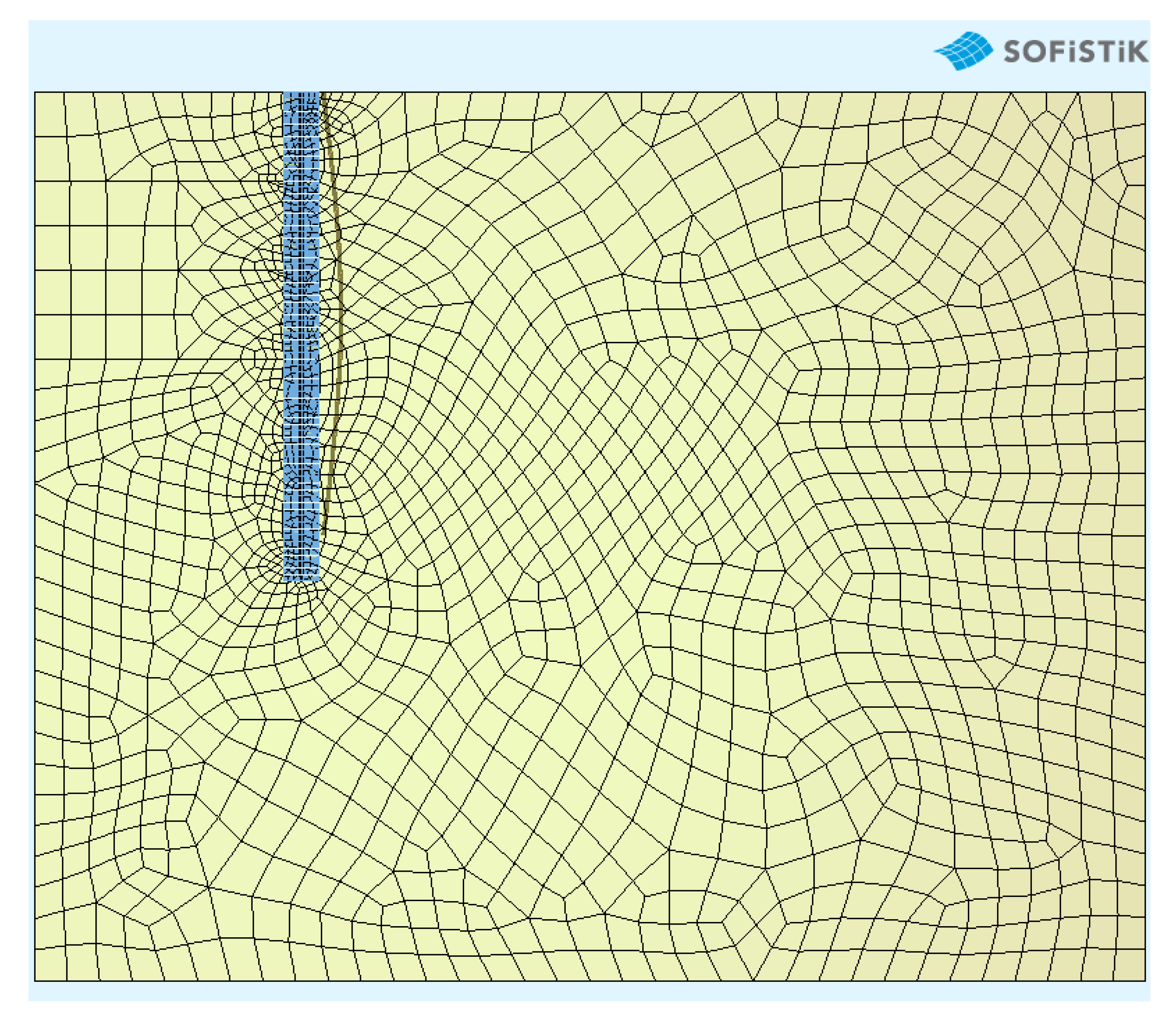
Figure 3 shows 2D and 3D views of the geometric model of the discussed solution as created in the Sofistik software. The next step is to generate the solid elements of the model (see
Figure 4).
Figure 4 shows correlation between structural elements and materials of the model. Due to the nature of the analysis, the same type of finite elements cannot be used for soil solids and diaphragm walls. Finite elements should be generated in such a way that their density is greater in places of stress concentration, while avoiding an excessive quantity of them, specifically within the soil-reinforced concrete interaction (interface), as this considerably extends the numerical calculations. It is necessary to wisely agree on the scope and size of finite elements, because an increased number does not necessarily translate into greater quality of results.
4. Discussion
The next step in creating a geometric model is to support it. It is impossible to find FEM solutions without problematic boundary conditions [
28]. Each of the model nodes must have certain degrees of freedom according to which the node can be displaced. Of course, the extreme nodes on the outer surfaces of the model demand the most attention. Entering the boundary conditions for these surfaces is relatively easy, because Sofistik has commands that strictly define the support conditions for selected nodes. It is essential to block the first surface with respect to displacements in the
y-direction, while allowing displacement in the
x- and
z-directions and free rotation. It is more difficult to set the boundary conditions for the soil-structure contact. This is a fairly extensive issue and the software dedicated to such analysis has functions that automatically determine the conditions of such interaction―it is enough to properly indicate the contact. In Sofistik, it is necessary to manually enter the principles of interaction between two different materials, e.g., the ground and the diaphragm wall (see
Figure 5).
Figure 5 shows constraints on elements, such as those that would occur along the interface between soil and the diaphragm wall, presented as one coherent environment. Without the establishment of this interaction, the obtained results do not correspond to real displacements, because the analyzed materials are completely different from each other and thus their constitutive matrices differ.
The Sofistik software has the TENDON function, which allows you to set the prestressing system according to the imposed rules. Understanding how this function works is extremely important, because later in the work, this algorithm will be adapted to the diaphragm wall in the ground environment. The following commands are used to insert the TENDON module into the model:
SYSP―this command allows for defining of the main assumptions of the prestressing system according to the instructions.
AXES―used to specify the type of the prestressing system and in which element the prestressing will be implemented.
TOPP and TGEO―determine the exact route of the unloading cable depending on the phase.
The prestressing system defined according to the above instructions should be adapted to the reinforced concrete element in which it is to operate, i.e., to the diaphragm wall. It begins at the stage of creating the prestressing geometry, i.e., the exact route of the prestressing cable in the element, and ends in the calculation module, which additionally accounts for the individual phases of the implementation of this concept.
The TOPP and TGEO functions allow for a non-linear definition of the prestressing cable, which is very advantageous in some technological situations, especially with greater diaphragm wall thicknesses. When the value of the bending moment due to earth pressure is significantly large, the non-linear course of the prestressing cable is effectively able to counteract the effects of these interactions. The results of the algorithm described in this subsection are presented below (see
Figure 6 and
Figure 7).
The authors made a comparative model in Plaxis―a trusted environment used in everyday geotechnical analysis—in order to verify the modeling results. Plaxis is undoubtedly one of the best and most well-developed tools for the analysis of the interaction of the structure with the soil. Sofistik has enormous potential and can be used for extensive analysis of different structures, such as bridges and tunnels, for example. Therefore, in the Plaxis 2D CE V20 software, an analogic model was developed using the same material parameters, phases and boundary conditions, with the results then compared to those generated by Sofistik.
Phasing adopted for model validation was:
Phase I―"in situ" (initial state);
Phase II―diaphragm wall installation;
Phase III―excavation 4.0 m deep.
The depth of 4.0 m was determined for the model comparison based on experience in situations with no external loads in order to simplify verification of the correctness of displacements. This makes it possible to adapt the previously created prestressing algorithm using analogic models in Sofistik, which is dedicated to such analysis. The comparison of the results began with checking the displacements in nodes with the same coordinates. The results of validation and comparison of the same models in the Sofistik and Plaxis environments are presented below.
Figure 8 and
Figure 9 show the identical nature of both models.
5. Conclusions
This article showed an alternative and innovative approach for the design and implementation of retaining structures. The authors presented the adaptation of known technological methods for the construction of the underground of buildings. The essence of the work was to present the results of numerical analysis in one coherent environment, so that it was possible to perform conceptual calculations. To be sure that their model results were correct, the authors validated the soil model in the popular Plaxis software, which is dedicated to geotechnical analyses (this comparison will be the subject of the next article). The compression algorithm itself was also prepared in the dedicated Sofistik development environment. This environment is commonly used for modelling bridge structures and includes a very well-developed prestressing module. Due to the geotechnical possibilities offered by this environment, the authors analyzed these two environments in one model: geotechnical aspects and prestressing. The result of this analysis is primarily the reduction of horizontal displacements, which translates to changes in the distribution of internal forces, which in turn affects the element dimensioning itself. The analysis showed that it is possible to reduce the amount of reinforcing steel [
29,
30], which directly translates into the cost of making a diaphragm wall (cost analysis will be described in the next article). Future research will also include technological issues and a cost comparison of a general example using both the classic and innovative approaches. Our results—using a relatively simple calculation with very neutral assumptions—clearly show the advantage of prestressing retaining structures. It is worth conducting more-detailed analyses to take into account the change in the geometry of the walls due to the applied prestressing in the form of shortening the wall, and the real savings in equipment and labor during the underground phase of construction using the method described here. The main advantages of the presented method are:
Relatively uncomplicated calculations;
Limitation of reinforcement use, important in the era of increasing steel prices;
Removing the anchors and struts leaves extra space for cranes to operate inside the excavation area;
Improvement of health and safety and minimalization of hazards within the excavation area;
Facilitation of sustainable construction of deep excavations.
The authors presented the concept of the research-calculation methodology for bonded prestressed diaphragm wall design, and they foresee unbonded prestress as an area for future research, taking into consideration that it could be innovative but only theoretical.


