Article

Fouling Identification for Nanofiltration Membrane and the Potential Reduction of Pollutants in the Leachate by Using Fe/Al/PAC Coagulation

1
College of Environmental and Chemical Engineering, Shanghai University of Electric Power, Shanghai 200090, China
2
School of Environmental Science and Engineering, Shanghai Jiao Tong University, Shanghai 200240, China
3
Shanghai SUS Environment Co. Ltd., No. 9, Songqiu Road, Shanghai 201703, China
*
Authors to whom correspondence should be addressed.
Sustainability 2021, 13(3), 1114; https://doi.org/10.3390/su13031114
Submission received: 22 December 2020 / Revised: 10 January 2021 / Accepted: 18 January 2021 / Published: 21 January 2021
(This article belongs to the Special Issue Wastewater Treatment and Solid Waste Management)

Abstract

:
The reduction in the fouling is an important way to maintain the steady operation for the nanofiltration (NF) process in leachate treatment. The fouling components from the real leachate treatment process were identified using a scanning electron microscope equipped with X-ray microanalysis (SEM-EDS), infrared spectroscopy (FTIR), atomic analysis and three-dimensional fluorescence (EEM) analysis, and the coagulation of Fe/Al/PAC was selected to reduce the potential pollutants in the leachate, to reduce the potential fouling. It was found that organic humic acid and calcium-magnesium precipitates were the main pollutants in NF fouling. The foulant layer was the result of the combination of organic matter, inorganic precipitation, colloids and microorganisms, and the colloids precipitation is more important, and should be removed in advance. PAC was found to be more efficiency to reduce the colloids and the inorganic matter, among the coagulants selection, with the chemical oxygen demand (COD) removal rate of 55.1%. The commercially available coagulant-poly aluminum chloride (PAC) was chosen as a coagulant. The removal rate of leachate reached 55.1%, and the flow rate through the membrane was increased by 35.8% under the optimum condition (pH was 5.0, PAC dosage was 100 mg/L, and the membrane pressure was 0.4 MPa). Through the pilot scale test, the effluent was connected to the microfiltration membrane and then to the nanofiltration membrane and the practical engineering application is feasible.

1. Introduction

Leachate from an incineration plant is substantially generated from discharge liquid during the process of garbage compression and maturation. It has the characteristics of high organic content, high suspended solids, and a high concentration of heavy metals. A complex composition of leachate was reported, which contains phenol, ammonia nitrogen, benzene, humic acid and some other aromatic or heterocyclic compounds [1]. Nanofiltration (NF) has been widely operated in the incineration plants to meet the discharges standards of COD < 500 mg/L, while the membrane fouling is the headache problem for the operators due to the complexity of the leachate components. After around 2 years, the NF membranes have to be substituted due to the heavy fouling even it was cleaned once every two months. Fouling is a big problem since most of pollutants in leachate, such as heavy metal, Ca/Mg and salt, are settled on the membranes, while the fouling components are still a barrier to reducing the potential fouling.
Membrane fouling can be divided into organic, inorganic, particulate and biological pollution [2]. For the problem of membrane fouling, the membrane surface contaminants are generally washed by means of cleaning [3,4,5], but it costs more, and leads to long-term frequent damage to the membrane, which is serious. Many physical-chemical treatments, including coagulation, adsorption, and advanced oxidation processes, have been proposed and studied for the effective removal of leachate [6,7]. However, these methods alone are insufficient for completely removing diverse organics from leachate [8]. Among several technologies currently available for treating leachate, membrane filtration such as NF [9] and reverse osmosis (RO) [10] has become an attractive option. Pretreatment + membrane bioreactor (MBR) + NF has become a typical technology for leachate treatment in order to meet the leachate discharge standard [11]. However, membrane fouling is considered a major demerit for the proper operation. This issue may require more frequent maintenance or even the replacement of the whole membrane assemblies [12].
Coagulation/flocculation (C/F) and granular activated carbon (GAC) adsorption are the most frequently used pretreatment options to mitigate organic fouling and to improve quality of product water in the leachate treatment [13,14]. Coagulation [15,16] and sedimentation is one of the commonly used methods for treating leachate. Racar [17] concluded the optimization of coagulation with ferric chloride (FeCl3) as a pretreatment for nanofiltration, performed to reduce membrane fouling and achieve higher permeate quality. However, it is rare to find the analysis of specific components in membrane fouling and membrane elution solutions.
The main objectives of this paper are firstly to identify the real fouling compounds on the NF system from a leachate treatment process of the working incineration plants with 1500 t/d, and then to reduce the potential fouling problems with the introduction of the simple operation unit of flocculation and the variations of the organic matters along the poly aluminum chloride (PAC) + polyvinylamide (PAM) coagulation process. The fouling mechanisms and the reduction process were analysed and proposed.

2. Materials and Methods

2.1. Sampling Site

Leachate samples were collected from the leachate treatment system attached to Zhangzhou Waste Incineration Power Plant in Ningbo, Zhejiang, with the disposal of 800 tons/day. The plant employs a typical process concluding anaerobism, a combined two-stage A/O, UF, NF and RO, which is a typical process for leachate treatment in China. The membrane system is designed and operated according to the standard of 1000 tons/day, while 10% is reserved. The water filtration rate of the NF system is no less than 85%, and that of the RO system is no less than 75%. Three incineration leachate samples were obtained from the leachate treatment plant attached. The quality of waste water and emission standards of incineration leachate are provided in Section 1 of the supplemental information (S1).
The fouling samples were collected from working incineration plants in Ningbo.
NF membrane for foulant research was taken from the damaged NF membrane (Figure S2) after elimination from the system. Membranes for the fouling experiments were stored at 15 °C. For FTIR, membrane samples were stored dry at 60 ℃.

2.2. Coagulation Process

FeCl3, poly ferric sulfate (PFS), ferrous sulfate (FeSO4), aluminum chloride (AlCl3), PAC, and poly aluminum ferric chloride (PAFC) were selected as coagulant. pH (3.5–8.0) and concentration of coagulant (10–200 mg/L) were optimized for coagulation. In order to explore the factors of COD degradation concentration, the controlled variable experiment was carried out on the types, concentration and initial pH of the agents supplemental information (text S2). In order to weaken the effect of PAM, 40% cationic PAM was used and the dosage of 2 mg/L was fixed.
The jar test was conducted using a laboratory set-up with a six-in-one electromotive stirrer. Samples of NF influent with defined pH values (adjusted using 0.1 mol/L HCl and 0.2 mol/L NaOH) were fed into 500 mL beakers and stirred for 3 min to achieve homogenous conditions. A coagulation test was performed by adding defined volumes of coagulant while stirring at 200 rpm for 2 min to disperse the coagulant, followed by 18 min of slow stirring (60 rpm) while adding PAM to ensure the floc growth, and 30 min of sedimentation. Samples (30 mL) were carefully extracted about 2 cm below liquid level. Samples were filtered with 0.45 μm cellulose acetate (CA) filters before the analysis of COD, FTIR, 3D-EEMs and UV/vis.
The microfiltration-ultrafiltration-NF membrane separation experiment machine (Figure 1) for coagulation pretreatment was purchased from Bona Biological Group. According to the procedure described, coagulation was carried out at optimal conditions for the beaker test to produce 1L of treated sample. After the coagulation, NF was performed at 0.4 MPa.

2.3. Measurements and Methods

2.3.1. Fundamental Parameters

pH was measured by pH meter (HQ30d, Hach, Loveland, Co, USA). COD was determined in accordance with the Standard Methods (GB11914). The influence of chloride on chemical oxygen demand is masked by adding mercury sulfate reagent. An atomic absorption spectrometer (ICE-3500, Thermo Fisher Scientific Logo, Shanghai, China) was used to measure the metal content of the samples such as Ca and Mg.

2.3.2. Spectroscopy Analysis of DOM

Chemical changes of the DOM extracted from the leachate samples and the NF membrane were quantification assessed by the spectral methods including UV-Vis, FTIR and EEM fluorescence.
The UV-Vis absorption was measured in the spectra range 200–800 nm by variable wavelength spectrophotometer (UV-2800A, UNICO, Shanghai, China) and a quartz cuvette with a 1-cm-path length. For the study of the spectral properties of DOM, the absorbance is commonly used to characterize the geochemical properties of DOM, such as the ratio of absorbance at 254 nm and 365 nm (E2/E3) to characterize the molecular weight of DOM [18,19]. Additionally, the ratio of absorbance at 465 nm and 665 nm (E4/E6) reflects the degree of DOM humification and aroma [20]. UV254 mainly represents refractory organic substances with unsaturated double bond structures such as phenols and aromatic compounds, which have unsaturated C=C and C=O. It can indirectly reflect the relative content of unsaturated double bonds or aromatic organic compounds in the test substance [21].
The infrared spectra (FTIR) was recorded from pellets containing 2 mg of the freeze-dried humic acids with 250 mg of dry KBr. The instrument used was a Spectrum Two FTIR spectrophotometer covering a wavenumber range of 400–4000 cm−1 at 0.5 cm/s [22]. The mixtures were pressed into pellets prior to FTIR spectra analysis.
The fluorescence measurement of the aqueous extract was conducted using a RF-5301 spectrometer (Shimadzu, Kyoto, Japan). To obtain the fluorescence spectra of excitation emission matrix, both of the excitation wavelengths and the emission wavelengths increased from 220 to 500 nm and the step length was 5 nm.
Prior to analysis, membrane coupons were further cut into smaller pieces and dried in a vacuum for 24 h. SEM was also used to obtain preliminary information of elemental composition of the fouled membranes on the overall surface. These measurements were made by using a Tungsten filament scanning electron microscopy with integrated EDS analyzer at an acceleration voltage of 5000x magnification.
MATLAB is used to edit the data of EEM. Origin 8.0 (USA) was used to generate contour plots and to process the spectra.

3. Results and Discussion

3.1. Fouling Components Identification

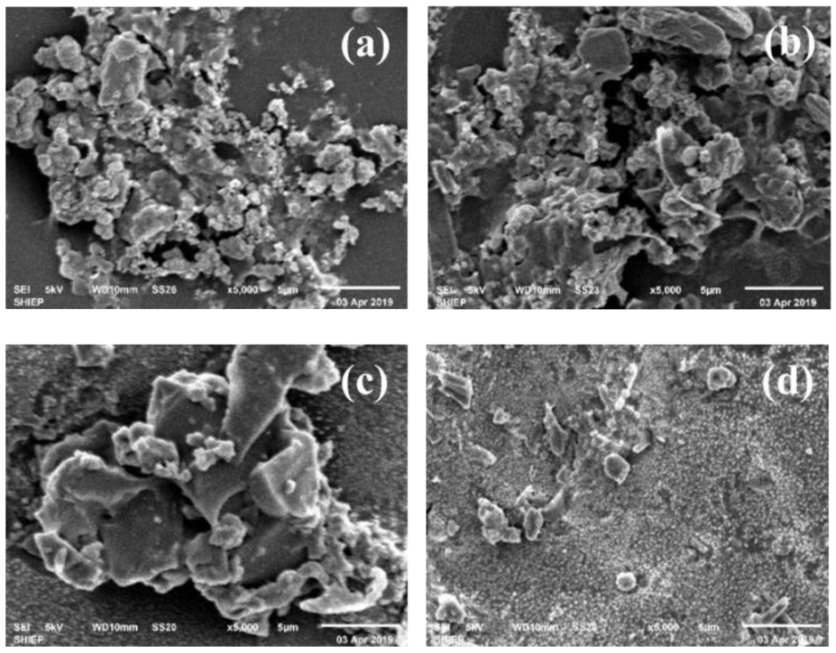
3.1.1. SEM Appearance

The presence of particles can be clearly seen in the SEM image of the broken nanofiltration membrane from the edge and the middle (Figure 2). It could be clearly seen that the cluster structure was formed by the pollutants on the surface of the NF film. Large-scale flocculent pollutants were observed on the surface of the film, and the scanning electron microscope image was clear.
According to EDS (Figure 3 and Figure S3), the main elements in membrane scale were C, N, and O, which indicated that the major pollutants in membrane scale were organic matters [23] and their combined weight ratios are as high as 86.74% (a), 87.52% (b), 94.11% (c), and 84.75% (d). Trace amounts of Na, Si, Cl, K, Ca, Fe, Zn, Al, S were also obtained and these inorganic elements were possibly the main reason for the fouling of the active layer of the membrane and caused the membrane flux of the nanofiltration system to continuously decrease [24]. Through complex process involving crystal nucleation or transport mechanisms, fouling of the membrane appeared [25]. Inorganic ions may exist in the form of nanoparticles or colloidal particles and they are deposited on the surface of the film [26]. Al and Si may mainly appear as SiO2 colloids and Al(OH)3 colloids since it was difficult for Al and Si to form inorganic precipitates in the leachate. Ca may form complex compounds with natural organic matter (NOM), thereby facilitating the subsequent formation of intermolecular bridges between organic foulant molecules and enhancing membrane fouling [27]. Li [28] confirmed that the interaction between foulant and foulant plays an important role in determining the incidence and extent of organic foulant. Strong foulant-soil adhesion allowed the foulant to accumulate on the membrane surface faster, therefore the formation of NF membrane fouling may be established when these inorganic precipitates were trapped on the membrane surface, and then SiO2, Al(OH)3 colloids could be adsorbed on its surface under the effect of van der Waals force and electrostatic attraction. The pores gradually became smaller, and organic matter and microorganisms continued to adsorb and accumulated on the surface [27]. Finally, a foulant layer of the nanofiltration membrane was formed. Thus, the foulant layer was the result of the combined reaction of organic matter, inorganic precipitation, colloids and microorganisms.

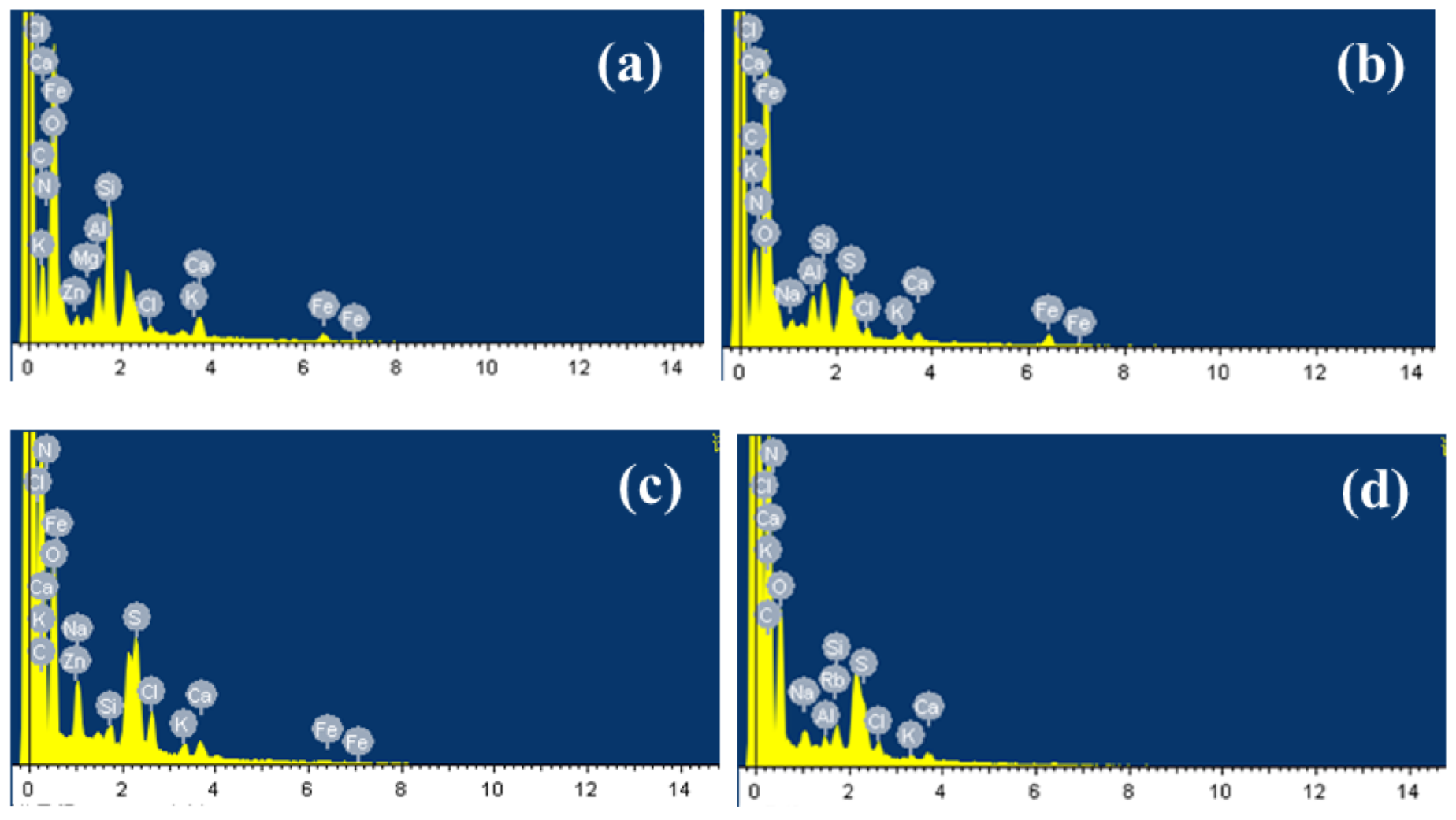
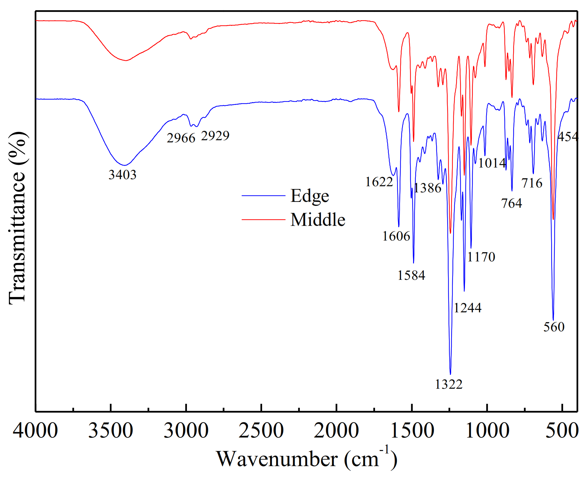
3.1.2. Fouling Components

FTIR was used to identify the organic materials, which were presented on the fouled membrane surfaces (shown in Figure 4). Slightly different absorbances were observed in some regions for all membrane-contaminated samples.
The main absorption bands were in the vicinity of 3403 cm−1 (O-H stretching; N-H), 1606 cm−1 (C=O stretching of amide I, quinone and ketones), 1244 cm−1 (S-O), 1170 cm−1 (C-N stretch; aliphatic amines), 764 cm−1 (C-H; aromatics), 716 cm−1 (C-O) and 560 cm−1 (corundum-based oxides). The adsorption band at 1606 cm−1 (amide group) was related to amide groups of protein or amino sugars [23] and the broad adsorption peak at 3403 cm−1 indicated the presence of polysaccharide-like substances in the fouling layer [29]. In the spectrum, 700–400 cm−1 was the band of corundum structure oxides Al2O3 (560 cm−1) and Fe2O3 (454 cm−1). It was estimated that Al(OH)3 and Fe(OH)3 colloids were also the foulants in the scale [30]. These regions were the main components of the soil layer analyzed by FTIR and the results were similar to the SEM analysis.

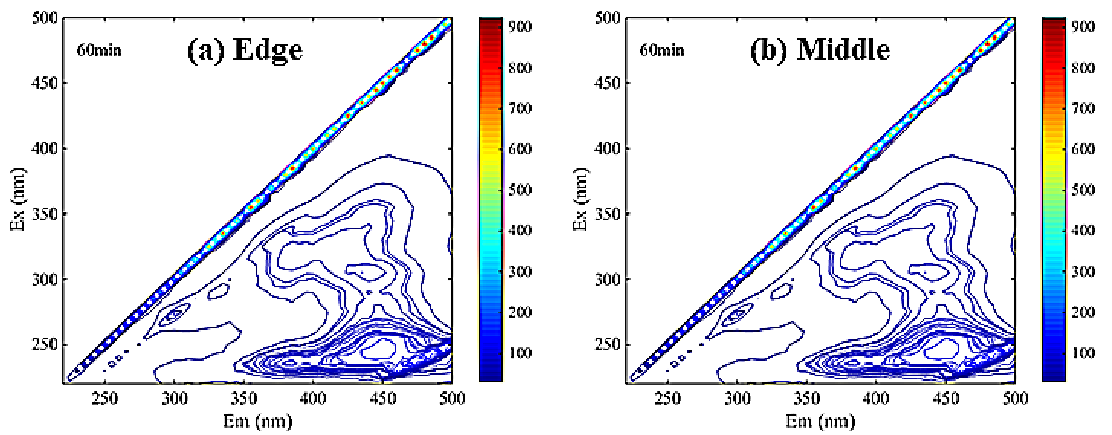
3.1.3. Membrane Soaking Solution Analysis

Metal Ion Contents

Studies have shown that hydrochloric acid had a good cleaning effect on the membrane, and the inorganic pollution on the membrane surface was basically removed, but organic pollutants such as organic acids, proteins and polysaccharides on the membrane surface could not be completely and effectively removed. As is shown in Table 1, the soaking solution contained a small amount of Fe, Al, Zn, and Mg, but a high concentration of Ca. The results were similar to the EDS analysis. Precipitate and aggregate of inorganic salts polluted membrane surface. It was also proven that Ca is an important inorganic element in the formation of membrane pollution.

Dissolved Organic Matter Contents

The EEM spectrum of DOM was divided into five continuous regions. Region I, II, III, IV and V have excitation/emission wavelength ranges of 230–250/280–330 nm, 230–250/330–380 nm, 200–250/380–520 nm, 250–440/280–380 nm and 250–440/380–520 nm, respectively [31].
As is shown in Figure 5, the main peaks of DOM in membrane soaking solution were concentrated in region III. It can be inferred that there were many fulvic acid-like substances in the scale-like soaking solution, which was consistent with the SEM-EDS analysis results.
Analysis results of the EEM fluorescence were supported by the UV-Vis. The UV-vis absorbance ratios, calculated by E2/E3 = A250/A365, E3/E4 = A300/A400, E4/E6 = A445/A665, had been used to reflect the process of humification [32,33]. E2/E3 can reflect the ratio of DOM molecular size. The larger the ratio was, the higher the proportion of small molecular substances was in the leachate sample. Therefore, it indicated that the content of small molecular substances in the scale-like soaking solution were higher. A large radio of E3/E4 indicated that the degree of humification was low. E4/E6 can represent the degree of polymerization of the carbon skeleton in the benzene ring. The smaller the ratio was, the better the degree of polymerization was. In addition, E4/E6 was also related to the molecular weight of organic matter. When the molecular weight decreased, the ratio tended to increase. Therefore, it was concluded that the molecular weight of the membrane scale soaking solution was small and the degree of humification was low from the analysis in Table 2. The membrane surface pollution of the nanofiltration membrane was more likely to be caused by the accumulation of fulvic-like substances.

3.2. Coagulators and the Operation Conditions Opitimized

3.2.1. Removal Potential
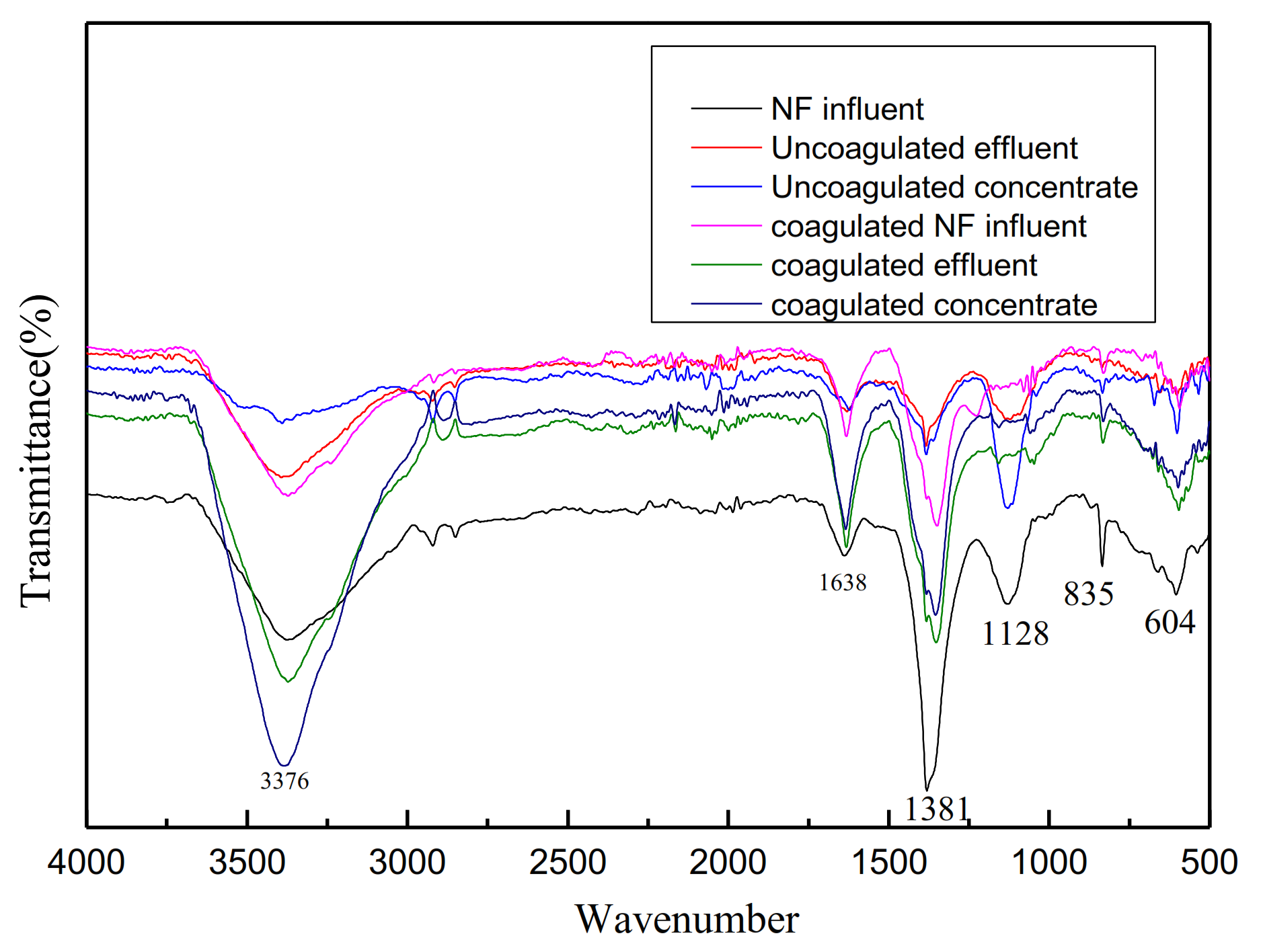
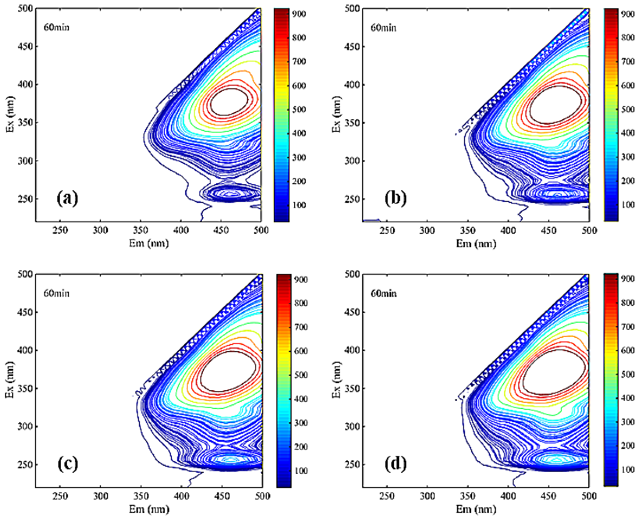
In order to test the efficiency of coagulation, which is a pretreatment to solve membrane fouling, the effluent from coagulation was subjected to the same conditions as the NF system of the incineration plant.
Six chemical compounds, named FeCl3, PFS, FeSO4, AlCl3, PAC, PAFC, were screened from coagulation processes, provided in Section 2 of the supplemental information (text S2). It was shown that PAC was the best one, which has been optimized using the single-factor experiment. In general, the use of PAC was recommended as the optimal coagulant.
As can be seen from Table 3, in the condition of using 100 mg/L PAC, the removal rate of COD condensed to NF was 5.1% in the membrane separation experiment after NF influent water coagulation and the membrane flow rate after coagulation increased by 35.8%, which may indicate that the coagulation treatment can effectively remove organic matter, reduce membrane pollution, increase fresh water membrane flux, and extend membrane system life.
As shown in Table 4, the cost of Using PAC as coagulant is low. The coagulation sedimentation integrated equipment with a daily treatment capacity of 30 m3/h is adopted for the treatment of nanofiltration influent, and the unit price of the equipment is only 150,000 yuan; the dosing is through the automatic control system, which does not involve the problem of personnel hands; the power consumption will only be slightly increased, and the actual engineering application is feasible.

3.2.2. DOM Removal

It can be seen from Table 5 that UV254 decreased after coagulating and the decrease degree was even lower after NF membrane treatment, which indicated that coagulation and NF technology can effectively degrade complex macromolecular organic matter and reduce the molecular weight and complexity of organic matter in leachate. E3/E4 of coagulated effluent was greater than that of uncoagulated effluent, which indicated that the degree of humification was decreased. After coagulation and NF, E3/E4 and E4/E6 in the influent increased from 3.38 and 1.86 to 6.75 and 10.45, respectively, which indicated that the humic acid-like substances were removed by coagulation.
Infrared analysis of water quality before and after NF influent coagulation was shown in Figure 6. The peaks at 1638 cm−1 (amide I, CO stretching vibration), 1380 cm−1 (C-H bending vibration), and 1128 cm−1 (C-O stretching vibration) were characteristic of organic matters such as proteins, polysaccharides, and amino sugars [34]. After the treatment of coagulation and NF membrane, the wave peak decreased obviously, which indicated that the removal effect was obvious.
It can be seen from Figure 7 that two main peaks were identified in the fluorescence spectrum of each solution DOM. One main peak was located in region III related to the fulvic acid substance, and the other main peak was located in region V related to the humic acid substance.
The significant differences among Figure 7a,b clearly reflected the main peaks in region III undergo a blue shift. Blue shift represented the reduction in polar groups (carboxyl group, amino group, hydroxyl group, etc.) in the leachate samples [35]. Therefore, the mutual repulsion between similar acid and membrane surface in the ultraviolet region was relatively low during the filtration of NF membrane. Additionally, it is easy to pass through NF membrane, which indicated that the pollutants on the membrane surface may be similar to the concentration of similar acid. The other main peak in region V from Figure 7a–f was obviously not changed during coagulation and NF, indicating that humic acid may be a difficult-to-remove membrane contaminant.

4. Conclusions

Interaction of organics, inorganic precipitation, colloids and microorganisms result in NF membrane foulant. SEM-EDS analysis showed that the main elements in the film scale were C, N, O, which indicated that the film scale contained organic matter. Content of Al, Si, Ca, Fe, and S in the scale was relatively high, which contained SiO2 colloid, Al(OH)3 colloid, Fe(OH)3 colloid and other inorganic precipitates. The analysis of the soaking solution showed that the main inorganic component was Ca salt, which contained a certain number of compounds such as Fe, Al, Zn and Mg. The main organic component was fulvic acid-like substances.
In this study, PAC was used as a coagulant to pretreat the NF water to reduce membrane fouling. The optimal pH is 5 and the optimal concentration is 100 mg/L. It proved that coagulation had a significant effect on reducing the polluted organic matter and could effectively increase the membrane flux. Through this study, it was recommended to use coagulation- and sedimentation-integrated equipment for NF influent coagulation and sedimentation treatment.

Supplementary Materials

The following are available online at https://www.mdpi.com/2071-1050/13/3/1114/s1, Figure S1: Flow diagram of the leachate treatment and sampling spots, Figure S2: Damaged NF membrane at the NF system, Figure S3: Coagulation effect of different chemicals and different pH coagulation, Figure S4: Effect of dosage on the coagulation effect under different concentration, Table S1: General indicators of leachate quality for each treatment process, Table S2: Proportion of main elements of NF membrane fouling.

Author Contributions

Formal analysis, Z.-y.L.; Investigation, L.-c.W. and H.-f.Z.; Methodology, Z.-y.L.; Project administration, L.-c.W.; Resources, L.B.; Supervision, Z.Z.; Writing—original draft, C.-w.H.; Writing— review & editing, H.W. All authors have read and agreed to the published version of the manuscript.

Funding

This research was funded by Shanghai SUS Environment Co. Ltd. and the research was supported by the College of Environmental and Chemical Engineering, Shanghai University of Electric Power and the School of Environmental Science and Engineering, Shanghai Jiao Tong University.

Institutional Review Board Statement

Not applicable.

Informed Consent Statement

Not applicable.

Data Availability Statement

The data presented in this study are available on request from the corresponding author. The data are not publicly available due to privacy.

Acknowledgments

This work was finally supported by the project foundation of Shanghai SUS Environment Co. Ltd.

Conflicts of Interest

The authors declare no competing financial interest.

References

  1. Schmidt, M.W.I.; Torn, M.S.; Abiven, S. Persistence of soil organic matter as an ecosystem property. Nature 2011, 478, 49–56. [Google Scholar] [CrossRef] [PubMed] [Green Version]
  2. Aguiar, A.; Andrade, L.; Grossi, L. Acid mine drainage treatment by nanofiltration: A study of membrane fouling, chemical cleaning, and membrane ageing. Sep. Purif. Technol. 2018, 192, 185–195. [Google Scholar] [CrossRef]
  3. Al-Amoudi, A. Nanofiltration membrane cleaning characterization. Desalination Water Treat. 2016, 57, 323–334. [Google Scholar] [CrossRef]
  4. Ilyas, S.; De Grooth, J.; Nijmeijer, K. Multifunctional polyelectrolyte multilayers as nanofiltration membranes and as sacrificial layers for easy membrane cleaning. J. Colloid Interface Sci. 2015, 446, 386–393. [Google Scholar] [CrossRef] [PubMed]
  5. Jiang, W.L.; Gao, X.; Xu, L. Investigation of synchronous arsenic and salinity rejection via nanofiltration system and membrane cleaning. Desalination Water Treat. 2016, 57, 6554–6565. [Google Scholar] [CrossRef]
  6. Liu, Z.P.; Wu, W.H.; Shi, P. Characterization of dissolved organic matter in landfill leachate during the combined treatment process of air stripping, Fenton, SBR and coagulation. Waste Manag. 2015, 41, 111–118. [Google Scholar] [CrossRef]
  7. Renou, S.; Givaudan, J.G.; Poulain, S. Landfill leachate treatment: Review and opportunity. J. Hazard. Mater. 2008, 150, 468–493. [Google Scholar] [CrossRef]
  8. da Costa, F.M.; Alves Daflon, S.D.; Bila, D.M. Evaluation of the biodegradability and toxicity of landfill leachates after pretreatment using advanced oxidative processes. Waste Manag. 2018, 76, 606–613. [Google Scholar] [CrossRef]
  9. Andrade, L.H.; Aguiar, A.O.; Pires, W.L. Nanofiltration and Reverse Osmosis Applied to Gold Mining Effluent Treatment and Reuse. Braz. J. Chem. Eng. 2017, 34, 93–107. [Google Scholar] [CrossRef] [Green Version]
  10. Labiadh, L.; Fernandes, A.; Ciriaco, L. Electrochemical treatment of concentrate from reverse osmosis of sanitary landfill leachate. J. Environ. Manag. 2016, 181, 515–521. [Google Scholar] [CrossRef]
  11. Fudala-Ksiazek, S.; Pierpaoli, M.; Luczkiewicz, A. Efficiency of landfill leachate treatment in a MBR/UF system combined with NF, with a special focus on phthalates and bisphenol A removal. Waste Manag. 2018, 78, 94–103. [Google Scholar] [CrossRef] [PubMed]
  12. Sir, M.; Podhola, M.; Patocka, T. The effect of humic acids on the reverse osmosis treatment of hazardous landfill leachate. J. Hazard. Mater. 2012, 207, 86–90. [Google Scholar] [CrossRef] [PubMed]
  13. Ang, W.L.; Mohammad, A.W.; Benamor, A.; Hilal, N. Hybrid coagulation-NF membrane processes for brackish water treatment: Effect of pH and salt/calcium concentration. Desalination 2016, 390, 25–32. [Google Scholar] [CrossRef]
  14. Smol, M.; Włodarczyk-Makuła, M. Effectiveness in the Removal of Organic Compounds from Municipal Landfill Leachate in Integrated Membrane Systems: Coagulation—NF/RO. Polycycl. Aromat. Compd. 2016, 37, 456–474. [Google Scholar] [CrossRef]
  15. Alfaia, R.G.S.M.; Nascimento, M.M.P.; Bila, D.M. Coagulation/flocculation as a pretreatment of landfill leachate for minimizing fouling in membrane processes. Desalination Water Treat. 2019, 159, 53–59. [Google Scholar] [CrossRef] [Green Version]
  16. Mariam, T.; Nghiem, L.D. Landfill leachate treatment using hybrid coagulation-nanofiltration processes. Desalination 2010, 250, 677–681. [Google Scholar] [CrossRef]
  17. Racar, M.; Dolar, D.; Spehar, A. Optimization of coagulation with ferric chloride as a pretreatment for fouling reduction during nanofiltration of rendering plant secondary effluent. Chemosphere 2017, 181, 485–491. [Google Scholar] [CrossRef]
  18. De Haan, H.; De Boer, T. Applicability of light absorbance and fluorescence as measures of concentration and molecular size of dissolved organic carbon in humic Lake Tjeukemeer. Water Res. 1987, 21, 731–734. [Google Scholar] [CrossRef]
  19. Peuravuori, J.; Pihlaja, K. Molecular size distribution and spectroscopic properties of aquatic humic substances. Anal. Chim. Acta 1997, 337, 133–149. [Google Scholar] [CrossRef]
  20. Choudhry, G.G.; Hutzinger, O. Photochemical formation and degradation of polychlorinated dibenzofurans and dibenzo-p-dioxins. Residue reviews. 1982, 84, 113–161. [Google Scholar]
  21. Dilling, J.; Kaiser, K. Estimation of the hydrophobic fraction of dissolved organic matter in water samples using UV photometry. Water Res. 2002, 36, 5037–5044. [Google Scholar] [CrossRef]
  22. Amir, S.; Jouraiphy, A.; Meddich, A. Structural study of humic acids during composting of activated sludge-green waste: Elemental analysis, FTIR and 13C NMR. J. Hazard Mater. 2010, 177, 524–529. [Google Scholar] [CrossRef] [PubMed]
  23. Zhao, Y.; Song, L.F.; Ong, S.L. Fouling behavior and foulant characteristics of reverse osmosis membranes for treated secondary effluent reclamation. J. Membr. Sci. 2010, 349, 65–74. [Google Scholar] [CrossRef]
  24. Chun, Y.; Zaviska, F.; Kim, S.J.; Mulcahy, D.; Yang, E.; Kim, I.S.; Zou, L. Fouling characteristics and their implications on cleaning of a FO-RO pilot process for treating brackish surface water. Desalination 2016, 394, 91–100. [Google Scholar] [CrossRef]
  25. Antony, A.; Low, J.H.; Gray, S. Scale formation and control in high pressure membrane water treatment systems: A review. J. Membr. Sci. 2011, 383, 1–16. [Google Scholar] [CrossRef]
  26. Xu, P.; Bellona, C.; Drewes, J.E. Fouling of nanofiltration and reverse osmosis membranes during municipal wastewater reclamation: Membrane autopsy results from pilot-scale investigations. J. Membr. Sci. 2010, 353, 111–121. [Google Scholar] [CrossRef]
  27. Mi, B.; Elimelech, M. Chemical and physical aspects of organic fouling of forward osmosis membranes. J. Membr. Sci. 2008, 320, 292–302. [Google Scholar] [CrossRef]
  28. Li, Q.; Elimelech, M. Organic fouling and chemical cleaning of nanofiltration membranes: Measurements and mechanisms. Environ. Sci. Technol. 2004, 38, 4683–4693. [Google Scholar] [CrossRef]
  29. Kerry, J.; Howe, K.P.I.; Clark, M.M. Use of ATR/FTIR spectrometry to study fouling of microfiltration membranes by natural waters. Desalination 2002, 147, 251–255. [Google Scholar]
  30. Sari, M.A.; Chellam, S. Reverse osmosis fouling during pilot-scale municipal water reuse: Evidence for aluminum coagulant carryover. J. Membr. Sci. 2016, 520, 231–239. [Google Scholar] [CrossRef]
  31. He, X.S.; Xi, B.D.; Li, X. Fluorescence excitation-emission matrix spectra coupled with parallel factor and regional integration analysis to characterize organic matter humification. Chemosphere 2013, 93, 2208–2215. [Google Scholar] [CrossRef] [PubMed]
  32. Zbytniewski, R.; Buszewski, B. Characterization of natural organic matter (NOM) derived from sewage sludge compost. Part 1: Chemical and spectroscopic properties. Bioresour. Technol. 2005, 96, 471–478. [Google Scholar] [CrossRef] [PubMed]
  33. Albrecht, R.; Le Petit, J.; Terrom, G.; Périssol, C. Comparison between UV spectroscopy and nirs to assess humification process during sewage sludge and green wastes co-composting. Bioresour. Technol. 2011, 102, 4495–4500. [Google Scholar] [CrossRef] [PubMed]
  34. Zheng, X.; Khan, M.T.; Croue, J.P. Contribution of effluent organic matter (EfOM) to ultrafiltration (UF) membrane fouling: Isolation, characterization, and fouling effect of EfOM fractions. Water Res. 2014, 65, 414–424. [Google Scholar] [CrossRef] [PubMed]
  35. Uyguner, C.S.; Bekbolet, M. Evaluation of humic acid photocatalytic degradation by UV–vis and fluorescence spectroscopy. Catal. Today 2005, 101, 267–274. [Google Scholar] [CrossRef]
Figure 1. Microfiltration + ultrafiltration + nanofiltration membrane separation experiment machine.
Sustainability 13 01114 g001
Figure 2. Figure 2. SEM of Nanofiltration (NF) membrane fouling. (a,b): middle sample magnified 1:5000, (c,d): edge scale magnified 1:5000.
Sustainability 13 01114 g002
Figure 3. EDS analysis results of NF membrane fouling (a,b): middle sample of NF film port magnied 1:5000. (c,d): edge scale of NF film magnified 1:5000.
Sustainability 13 01114 g003
Figure 4. FTIR of fouling and intermediate fouling at the edge of the membrane.
Sustainability 13 01114 g004
Figure 5. The EEM spectra of membrane scale soaking solution ((a). edge sample (b). middle sample).
Sustainability 13 01114 g005
Figure 6. Infrared analysis of water quality before and after NF influent coagulation.
Sustainability 13 01114 g006
Figure 7. Three-dimensional fluorescence spectroscopy analysis of NF coagulation leachate sample ((a). NF influent, (b). coagulated NF influent, (c). Uncoagulated effluent, (d). coagulated effluent, (e). Uncoagulated concentrate, (f). coagulated concentrate).
Sustainability 13 01114 g007aSustainability 13 01114 g007b
Table 1. Analysis of metal content in scale-like soaking solution.
Fe3+ (mg/L)Al3+ (mg/L)Zn2+ (mg/L)Mg2+ (mg/L)Ca2+ (mg/L)
Edge3.14.91.712.6157.0
Middle6.18.22.911.6213.2
Table 2. UV spectral analysis of scale-like soaking solution.
E254E2/E3E3/E4E4/E6
Edge0.106.536.331.50
Middle0.125.715.302.50
Table 3. Comparison of separation data between raw leachate and coagulation leachate after NF.
Experimental IndexUncoagulated Raw WaterAfter Coagulation
COD of influent, mg/L272 ± 11122 ± 5
Pressure, MPa0.4 ± 0.10.4 ± 0.1
flow velocity, L/h81 ± 3110 ± 5
Influent load, L1 ± 0.0051 ± 0.005
Effluent load, L0.9 ± 0.0050.935 ± 0.005
COD of effluent, mg/L215 ± 9106 ± 5
COD of concentrate, mg/L835 ± 36762 ± 33
Table 4. Technical and economic analysis of coagulation treatment of nanofiltration influent.
PharmacyUnit Price
(¥/ton)
Optimal pHOptimal Dosage
(mg/L)
Effluent COD
(mg/L)
Processing Costv
(¥/ton)
Processing Cost
(¥/g*COD)
PFS2.85.01001310.281.98
PAC25.01001060.201.2
PAFC98.01001710.303
AlCl3666.030 1061.9812
FeCl3284.51501474.233.6
FeSO4246.01501556.051.3
Table 5. Special absorbance values of DOM before and after membrane separation.
UV254E2/E3E3/E4E4/E6
NF influent4.123.053.381.86
Uncoagulated effluent2.884.405.9620.13
Uncoagulated concentrate2.934.205.9120.75
Coagulated NF influent0.3380.656.7510.45
Coagulated effluent0.2050.597.871.61
Coagulated concentrate0.2250.587.075.29
Publisher’s Note: MDPI stays neutral with regard to jurisdictional claims in published maps and institutional affiliations.

