Abstract
This research aims to develop a methodology for geometric analysis of the territory, which, by means of a specially designed digital tool, allows quantitative assessments useful for drawing up sustainability policies. The difficulty of working with this type of procedure is the sectorialisation of technical skills among those who deal with design at the architectural scale and those who work at territorial scale. The undertaken methodology establishes a workflow that can export data from a GIS tool and import it into a three-dimensional modeler. To do this you need an intermediate tool, a parametric software. The explained procedure aims to have maximum freedom of model geometries processing. Therefore, it has been based on Nurbs mathematical models. The application tested with this is the solar radiation analysis in the territory of Ortona, Italy, on the Adriatic coast. Starting from the cartographic data of the Abruzzo Region, the three-dimensional model has been developed and it has built a base for further analysis. This working methodology ensures efficient results with a low amount of human iteration to generate the final model. Some of the procedure’s limitations have been explained in detail, mainly due to the structure of the used components.
1. Introduction
The premises that gave rise to this research work are the clear division between the modelling at architectural scale and modeling at territorial scale. In fact, the works relating to these two branches travel at different scales, with different tools and are generally carried out by different professionals. This methodology preconfigures, instead, a workflow that merges two worlds that usually travel in parallel with few contacts, but it could deliver synergic advantages, which derives from a controllable methodology on both fronts. The analysis of solar radiation, the case study of this work, is conducted on the individual building with instruments that work at the architectural scale. When this analysis is conducted at the urban/territorial scale, it neglects the presence of the third dimension. This creates enormous gaps in the analysis, which will be explained in detail.
The digital tool developed with this research, based on parametric and algorithmic methods, has an analysis capacity usable in multiple scenarios and at different scales. There are two purposes for which this methodology has been developed: The first is spatial analysis for sustainable mobility, and the second is for energy audits of buildings. The spatial analysis studies the possibility of increasing the accuracy of terrain modeling with Nurbs tools instead of traditional Mesh tools. This tool’s choice is due to the polygonal aspect of Mesh entities that distort the terrain because they are composed of polygonal meshes, as opposed to Nurbs objects that approximate the terrain more accurately.
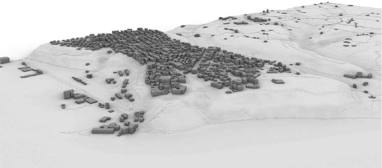
It is useful to have synergy between the spatial and urban scales because the same algorithmic tools can be applied in both contexts, within the data’s granularity and precision. Such analyses are affected by precision, which is proportional to the decrease in scale, losing meaning at the architectural scale. Hence, it is necessary to link the individual data to have a single system that provides results of acceptable precision at all levels of investigation. Based on these considerations and data available on the individual territories, it was considered appropriate to begin the acquisition of the territorial data from which it has been possible to deduce information that will be integrated with the data of the built environment at the urban scale (Figure 1).
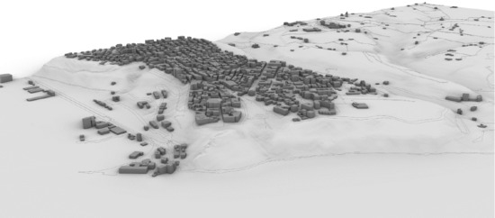
Figure 1.
NURBS model obtained from DTM raster.
The second purpose for which this methodology has been developed is the analysis of buildings for energy assessment purposes. Such analyses are usually conducted at the architectural scale, considering the features of a single building. With the present methodology, on the contrary, it is possible to make an estimate of an entire built-up area, because the precision of the data extrapolated from the territorial databases allows a useful characterisation for various analyses closely linked to geometry. Such analyses are of special value for advanced urban planning such as the “CPH 2025 Climate Plan” [1].
The data processing methodology explained in this work aims to facilitate the geometric manipulation and analysis of specific areas, starting from territorial cartographic data to get a three-dimensional model. The work has been developed within the Fragile Territories project at the Department of Architecture and Urban Studies of Politecnico di Milano, in collaboration with the Department of Civil, Building, Environmental Engineering and Architecture of Università degli Studi di L’Aquila.
The scientific literature regarding this specific work is not yet consolidated because illustrated methodologies, even if apparently similar to the one under discussion, present some differences, which are substantial when analyzing the results. Among others, a research which starts the analysis with a territorial modeling with Mesh technology [2] focuses on the use of DTMs for the digital reconstruction of parts of the territory to perform a NURBS analysis for hydroelectric engineering. In that case, the authors’ methodology offers reasons for the construction of a three-dimensional mesh model, starting from a DTM, using algorithms that exploit the Delaunay triangulation. The contour lines are subsequently extracted at a specific interval, and a NURBS surface is interpolated from them. However, the result suffers from a lack of data excluded from interpolation due to the sampling performed of the extraction of contour lines.
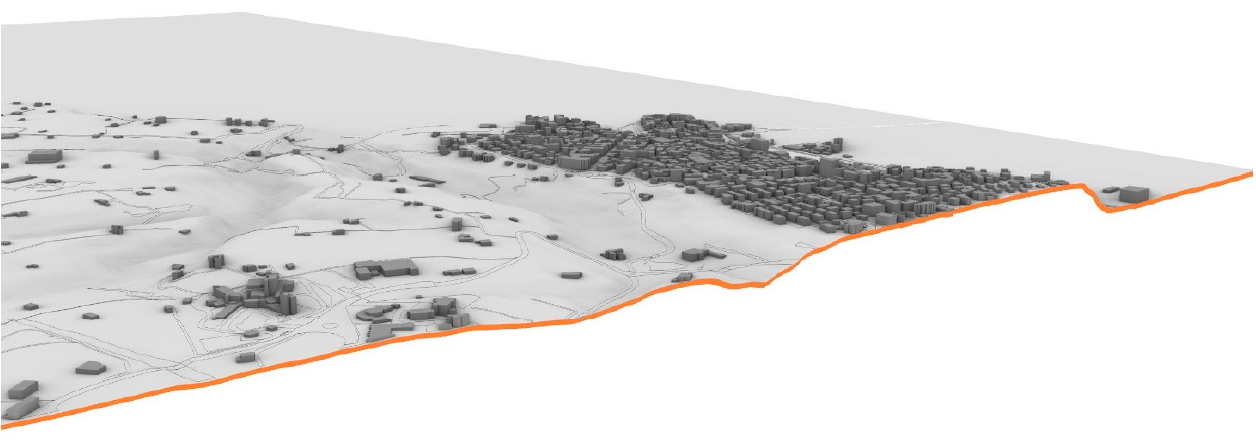
The methodology discussed in this paper uses tools belonging to the GIS family, and those typical of generative modeling [3]. The working methodology applies the elaboration of a territorial raster data—the Digital Terrain Model (DTM)—which is discretized into a two-dimensional grid of points, whose pitch corresponds to the precision of the DTM itself. Each point coordinate of the DTM is associated with an elevation z that transforms the grid into a three-dimensional network of points. The methodology produces a set of three-dimensional Nurbs vectors where different types of geometrical editing and analysis can be applied (Figure 2). The methods described above have been used in Ortona (Italy), which was chosen as the case study area.
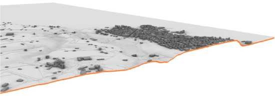
Figure 2.
Section of the NURBS model perpendicular to waterfront.
2. Research
To generate the case-study area’s parametric 3D model [4], data were found by selecting them in the Open Data cartographic database of the Abruzzo Region [5] In particular, the data relating to the raster DTM were used. DTMs represent the trend of the surface of the soil cleaned of all anthropogenic and vegetational elements. Digital terrain models are used to describe the morphology of the territory; they are structured in grids where its interpolated height determines each point. The grid of the DTM used is square, and each element measures 10 m × 10 m; this allows it to have sufficiently accurate data as a starting point. The processing of these data required a rather complex procedure.
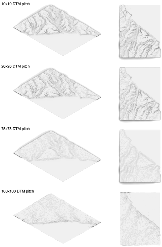
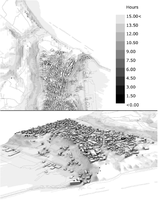
The other databases used were those of the D.B.T.R. (Regional Territorial Database) in 1:5000 scale, containing information and geometries about: geodesy; technological networks; administrative limits; areas of relevance, hydrography, orography; vegetation. To manage this amount of data in three dimensions, the use of Grasshopper [6]—a digital parametric tool designed for a visual scripting language—was paramount. In this way, the procedure gets as an output, a cloud of georeferenced elevation points that faithfully represent the territory’s portion. For this purpose, instead of meshes, the mathematical structure commonly known as Nurbs [7] has been chosen. This procedure can generate a surface passing through each point of the three-dimensional grid; this decision was due to a Nurbs modeler’s inner strength as Rhino, which bases his strength and operational efficiency on the generation and manipulation of entities of mathematical type. The amount of information required for the NURBS representation of a geometric element is far less than the amount of information required to represent the same geometry by mesh approximations [8]. Furthermore, mesh approximation is made by polygonal shapes, which are not compatible with natural forms. The representation of a landscape is more coherent with organic forms, mainly made of curved shapes. One example of the flexibility of NURBS architecture is the possibility of easily extracting curved contour lines from a landscape, while applying the same transformation to a mesh surface, the result will be polygonal. NURBS are not always the best pick for this type of operation. For extensive portions of terrains Mesh models can lighten the computational burden and speed up the algorithm using the Delaunay triangulation, skipping calculations of all the parameters necessary to create the mathematical surface. In Figure 3, (drawing on the bottom) where the precision is lower, the use of NURBS is overabundant, because mesh can achieve a similar result with a lower computation. On the top drawing of the same figure, instead, a mesh representation would highly impact on the definition of the landscape, thus, a NURBS representation is desirable. In Figure 4, there is a simultaneous presence of Nurbs and mesh representation. Building and landscape are Nurbs, the solar weather data (as described below) are mesh, so they can give a rough idea of how the landscape would be less precise if it would have been built by mesh Only.
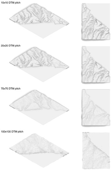
Figure 3.
Comparison between 3D models of the case study obtained from DTMs with different pitches.
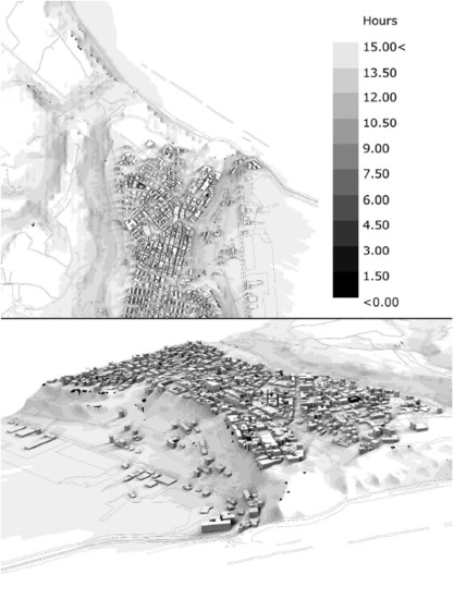
Figure 4.
Results of the sunlight analysis in both planar and axonometric view.
The procedures used to represent the other vectorial data (buildings, urban perimeters, railways, roads, sheep tracks, ski resorts) are similar to those described above. Some steps of this procedure have peculiar cues for further elaborations and research. In particular, in the structuring of the algorithm aimed at displaying the buildings, after importing the points and creating first-degree interpolation lines between them, the problem encountered was obtaining vertical, closed extrusions of a value equal to the exact height of the buildings. This request became indispensable because the case-study area was the subject of an energy analysis based on individual buildings’ geometric data. To solve the first problem, the geometries’ centroids were extracted utilizing the Grasshopper component “Area” and projected onto the NURB main surface. Subsequently, the geometries were translated vertically along the vector that connects the centroids to their projections and then extruded by a value equal to their real height from the data associated with each geometry (contained in the attribute table of the initial shapefile). The analysis of the territory made with Nurbs tools offers the possibility to have more suitable models for the definition of mobility routes, as explained in [9].
The same model can be used to carry out energy analyses of the buildings. It is possible, through the combination of parametric tools such as Ladybug [10] to combine EnergyPlus weather files (EPW) and three-dimensional (3d) model for better understanding of the weather data and to visualize the building performance analysis results. A basic example of this analysis is shown in Figure 4, where solar hours are drawn within an illuminance; multiple energetic and environmental analysis can be conducted with the same methodology, within the same digital ecosystem. The procedure is strictly connected to the database contained in the EPW that stores daily data regarding average ground temperatures and sun positions recorded by monitoring systems in certain areas during the entire year. Italy does not have a uniform coverage of weather data-collecting stations and in this case the closest one is in Pescara (which is 30 km away from Ortona). The algorithm used to perform the already mentioned analysis bases its strength on projecting a mesh of a certain pitch on the 3D model (3 m for the case-study, shortest pitches requires longer computational times but guarantee higher precision). Ladybug generates sun vectors drawing data from the EPW for the chosen location and calculates shadows casted from buildings and terrain accordingly. Colors in Figure 4, as explained in the legend, portray how many hours that area is exposed to direct sunlight in a specified day or period of time (21 June in this case). In this way it is possible to understand the perceived potential outdoor comfort (or discomfort). This kind of simulation could be helpful in thinking about a way of urban and territorial planning that takes into account environmental aspects, with consciousness and awareness of phenomena taking place at small and large scale. The municipality of Copenhagen is a forerunner in this sense. Since 2011, according to the Municipal Master Plan, new urban development areas have been constructed so that construction must comply with requirements of Energy Class 2020 Using local and remote monitoring and simulation methodologies like the one described in this paper grant planners and stakeholders energy-efficient results.
The applied methodology starts its procedure from two sources, both taken from the open Abruzzo geodatabase, the first provides the raster Digital Elevation Model, which is the base for the terrain analysis: [11]. The second is the vectorial Digital Technical Regional Map which is the base for buildings and map signs: [12]. Once the parametric 3D model has been built, all the weather data may be retrieved from many sources, it was chosen EnergyPlus: [13]. The complete modeling procedure has been explained step by step in [14].
Further developments and benefits for both designers and users lay on monitoring those results in time, comparing them with input values calculated during the planning phase.
3. Issues and Future Development
There are some issues connected with this procedure, which is worth examining. The first shrewdness is the check of system coordinate in GIS for the element to be imported into Grasshopper. Built into the Import component, there is a universal converter into WGS84 Coordinate Reference Systems (SR), but different experiments have proved this function to be not wholly reliable. Therefore, a correct procedure is a verification that all of the imported elements have the same SR. For the purpose of this work, the export procedure from the GIS system was accomplished from a single file with a single SR to avoid any ambiguity.
The second issue is the limit of the chosen Grasshopper component. The generation of the surfaces passing through points works only if they are in a rectangular or square array. If any points are beyond this limit, the procedure does not work, and thus, it is necessary to delete these elements manually. In this experimentation’s specific case, where the surface represents a portion of terrain, the easiest solution is mending each Nurbs with the nearby. The methodology has been tested with different input DTMs, highlighting each scale’s criticality and strengths. It is evident how, as the level of definition increases, the quality of the 3D model improves. It also increases the computational complexity that makes it challenging to manage, especially for areas in the order of tens of kilometers, such as that of the case study. Two strategies have been developed to overcome this problem. The first is to use a DTM where the initial accuracy is lower. This strategy, shown through the contour lines in Figure 3 by comparing the DTMs at 10- and 75-m pitch, shows how some hilly reliefs perpendicular to the coast are cut sharply in the less accurate model (in blue). This type of inaccuracy undermines the primary purpose of the research, which is to model a territory with precision to be a solution only in the case of much larger areas of the case study. The second strategy is to perform basic raster repair operations that have resulted in a mesh with fewer vector points, and therefore, more manageable. This procedure overcomes the problem of the previous one because it changes the general trend of the territory. However, it is necessary to carefully evaluate the corrections locally made because artifacts could emerge due to the compression of the underlying raster images. Future development in this workflow is the definition of a boundary curve, which includes all the points imported into the algorithm. Once this curve has been defined, a culling procedure should be activated so that the outside points will be automatically deleted.
A third issue is the need of integration between 3D territorial models and specific data related to the building. This problem can be partially solved with the integration with Tabula web tools and EPISCOPE [15], which categorizes residential buildings by visual appearance (indirectly construction elements), heat supply systems and energy consumptions. This branch of the research is currently ongoing.
Further developments will include different environmental analysis at the urban scale. EPW files are not the only data source. Early experiments are focusing on the integration of multispectral satellite images in the algorithm to assemble even richer databases taking into account data about soil quality, trees health state, presence of asbestos on roofs and urban ground materials. Gathering and combining multi-source data is the key axis of this research. The aim is to structure an environmentally conscious urban design capable of hinging territorial and architectural design scale.
4. Conclusions
Based on the proposed methodology, the three-dimensional maps and models have been elaborated. They represent only one step, which highlights the effectiveness of the procedure. A first simple step forward is the possibility to coordinate the three-dimensional model with a georeferenced texture of the territory to get a photorealistic model of the landscape whose precision is limited only by the DTM mesh pitch. The explained procedure is provided with a certain degree of automation because it only needs to input the raster shapefile of DTM to provide the three-dimensional terrain model. It is an actual result because of the barrier, which separates the architectural and urban/territorial world. The application of this parametric design method to the territory could change its trajectory from a difficult research tool for non-experts to understand for software in everyday use by part of the actors of urban, territorial, and regional transformations with the aim to improve sustainability of human life.
Author Contributions
Supervision and Writing. D.D.; Writing—original draft, F.E. Both authors have read and agreed to the published version of the manuscript.
Funding
Publication produced with the contribution of the Territorial Fragility project of the Department of Architecture and Urban Studies of the Politecnico di Milano, within the framework of the 2018-2022 MIUR Departments of Excellence program and the contribution of Civil, Construction-Architectural and Environmental Engineering Department, Università dell’Aquila.
Institutional Review Board Statement
Not applicable.
Informed Consent Statement
Not applicable.
Data Availability Statement
Data availability detailed in references.
Conflicts of Interest
The authors declare no conflict of interest.
References
- Madsen, S.H.J.; Hansen, T. Hansen Cities and climate change—Examining advantages and challenges of urban climate change experiments. Eur. Plan. Stud. 2019, 27, 282–299. [Google Scholar] [CrossRef]
- Zhong, D.; Liu, J.; Li, M.; Hao, C. NURBS reconstruction of digital terrain for hydropower engineering based on TIN model. Prog. Nat. Sci. 2008, 18, 1409–1415. [Google Scholar] [CrossRef]
- D’Uva, D. Handbook of Research. Form and Morphogenesis in Modern Architectural Contexts; IGI Global: Hershey, PA, USA, 2017. [Google Scholar]
- Woodbury, R. Elements of Parametric Design; Routledge: London, UK, 2010. [Google Scholar]
- Opendata. Available online: http://opendata.regione.abruzzo.it/ (accessed on 29 October 2020).
- Tedeschi, A. AAD, Algorithms-Aided Design; Le Penseur Publisher: Brienza (Potenza), Italy, 2014. [Google Scholar]
- Catmull, E.; Clark, J. Recursively Generated B-spline Surfaces on Arbitrary Topological Meshes. Comput.-Aided Des. 1978, 10, 350–355. [Google Scholar] [CrossRef]
- Piegl, L. On NURBS: A Survey. IEEE Comput. Graph. Appl. 1991, 11, 55–71. [Google Scholar] [CrossRef]
- Bianchi, A.; D’Uva, D.; Rolando, A. An Innovational Digital Tool in GIS Procedure: Mapping Adriatic Coast in Abruzzo Region to Support Design of Slow Mobility Routes. WORLD 2020. [Google Scholar] [CrossRef]
- Roudsari, M.S.; Pak, M.; Smith, A. Ladybug: A Parametric Environmental Plugin for Grasshopper to Help Designers Create An Environmentally Conscious Design. In Proceedings of the BS2013: 13th Conference of International Building Performance Association, Chambery, France, 26–28 August 2013; pp. 26–28. [Google Scholar]
- DEM. Available online: http://opendata.regione.abruzzo.it/opendata/Modello_digitale_del_terreno_risoluzione_10×10_metri (accessed on 15 February 2020).
- CTRN. Available online: http://opendata.regione.abruzzo.it/opendata/CTRN_Regione_Abruzzo_1_5000 (accessed on 15 February 2020).
- EnergyPlus. Available online: https://energyplus.net/weather-location/europe_wmo_region_6/ITA//ITA_Pescara.162300_IGDG (accessed on 15 February 2020).
- D’Uva, D.; Eugeni, F. Mappatura Parametrica: Metodi di Rappresentazione Digitale del Territorio, Dagli Open Data al modello Nurbs. In Paesaggi Instabili; Aracne Editrice: Rome, Italy, 2019. [Google Scholar]
- Yuchen, Y.; Vahid, M. Assessing the impacts of climate change on the German building stock. In Proceedings of the 16th IBPSA Conference, Rome, Italy, 2–4 September 2019. [Google Scholar]
Publisher’s Note: MDPI stays neutral with regard to jurisdictional claims in published maps and institutional affiliations. |
© 2021 by the authors. Licensee MDPI, Basel, Switzerland. This article is an open access article distributed under the terms and conditions of the Creative Commons Attribution (CC BY) license (http://creativecommons.org/licenses/by/4.0/).

