Abstract
In this study the environmental performance of a first-of-its-kind integrated process based on supercritical water gasification and oxidation (SCW-GcO), was evaluated using life cycle assessment (LCA). The process was applied to the treatment of carbon black and used oil as model wastes. Mass and energy balances were performed using Aspen Plus, and the environmental assessment was carried out through SimaPro. A “from cradle to grave” approach was chosen for the analysis, considering impact categories such as climate change, ozone depletion, human toxicity, particulate matter, land use, resource depletion, and other relevant indicators. The environmental profile of the SCW-GcO process was compared to other technologies for the treatment of dangerous wastes, solvent mixtures, and exhaust mineral oils by using the Ecoinvent database. It is shown that SCW-GcO allows for reduced impacts in different categories and the obtention of a favorable positive life cycle energy balance, achieving good environmental performance.
1. Introduction
The enhancement of people’s living levels increases the volume of organic waste that is produced worldwide. Waste landfilling is an unsuitable method that leads to unacceptable occupation of land, polluted soil and water, and air pollution. New generation incinerators have reached a noticeable level of air pollution control, but some major drawbacks do continue to exist. On average, the efficacy of an incinerator to reduce the solid mass of waste is only 70%. Despite the low concentration of harmful pollutants at the stack (dioxins, fine particulates, and NOx), the total amount of pollutants emitted in the atmosphere is huge and it increases year by year.
In an influential report, the National Academy of Science expressed a substantial degree of concern about the effects of the incremental burden of emissions from multiple incinerators on a region, which can expose a very broad population to pollutants such as dioxin and some metals that are recognized as persistent, widespread, and potent [1].
Air pollution, disease extension, and social problems should encourage research into new technologies that are capable of overcoming drawbacks of landfilling and incineration. Supercritical water-based processes could be one such technology, if some technical problems were solved.
Supercritical water (SCW)-based processes were developed in the 1970s to exploit the extraordinary properties that water exhibits above its critical point (22.1 MPa and 374 °C): a drastic decrease in pH, dielectric constant, ionic product, viscosity, and thermal conductivity [2]. At these conditions, SCW essentially acts as a non-polar fluid with solvation properties resembling those of low-polarity organic fluids and is able to dissolve organic matter by breaking down molecules.
Properties of supercritical water have been exploited for the treatment of organic matter through two main processes: supercritical water gasification (SCWG) and supercritical water oxidation (SCWO). The main idea of SCWG is to benefit from the special properties of SCW as a solvent and reaction partner for the fast hydrolysis of organic matter and consequent production of pressurized gases (mainly H2, CH4, CO, and CO2). The high solubility of the intermediates in the reaction medium significantly inhibits tar and char formation, which is one of the main drawbacks of conventional gasification. Indeed, the reactive species originating from organic matter are solvated in water and consequently the reaction rate of polymerization to unwanted products such as tar and char is reduced. Altogether, this leads to high gas yields at relatively low temperatures [3].
SCWG has been mainly studied for the valorization of biomasses such as lignocellulosic materials, sewage sludge, wastes from the agro-food industry, and microalgae [4]. However, until now this technology has not found an industrial scale operating application.
The main drawbacks of SCWG are:
- The conversion of organics to gas is complete only in very limited cases. For instance, when the organic concentration is low (say <5 %wt), when the reactor temperature is very high (T > 700 °C), when special catalysts are used, or when the C/O mole ratio in the organic matter is low [5].
- SCWG needs a high amount of heat to bring water to operating conditions. This heat increases when the organic concentration is kept low [6].
- The amount of organic matter that is not converted to gas remains dissolved in liquid water after depressurization of the effluent stream. This polluted water has high organic content that must be treated as special waste [7].
In the case of SCWO, an oxidant (air or pure O2) is added to the reaction medium in order to fully oxidize the organic matter that is dissolved in water. The product gas is mainly composed of CO2, N2, and excess O2 [8]. Thanks to the relatively low temperature of the process (T < 800 °C) compared to conventional incineration, NOx and dioxins are not produced [9]. Acid substances such as HCl, H2SO3, and H3PO4 remain dissolved in liquid water after the cooling of the reaction phase, and so do not pollute the effluent gas [10].
SCWO is able to convert organic matters with yields in the order of 99.9% in a short residence time (30 to 180 s). The reaction is exothermic and a large part of the heat produced from the reaction can be recovered in properly designed heat exchangers downstream of the reactor [11]. Because oxidation transforms all organic matter into CO2, it is not exploited as a source of valuable gas and organic liquids when treated through SCWO. For this reason, SCWO is properly employed as a final stage of the treatment of wastes at the end of their life cycle. Another special application is that of very dangerous wastes that require a reaction environment with a high content of water. Some examples of special wastes treated through SCWO are explosive matter [12], polychlorinated biphenyls (PCBs), sewage sludge, spent catalysts, and chemical weapons [13,14].
The combination of the two technologies have been described in some papers. In a study by Qian et al. [15], a combined process for the treatment of sewage sludge was proposed. The aim of the process was to reduce the oxidant consumption in SCWO, using SCWG as a pretreatment of sewage sludge. No heat integration between the two reactors was considered. In their most recent study, Qian et al. [16] presented an experimental and thermodynamic study for a combined process of SCWG and supercritical water partial oxidation (SCWPO) using liquid oxygen. Wang et al. [17] studied a batch reactor that combined the degradation of Lurgi coal gasification wastewater (LCGW) with SCWO. Another work by Wang et al. [18] proposed a combined process for cocking wastewater treatment with separated reactors for oxidation and gasification. A countercurrent gasification–oxidation reactor was also proposed in a patent [16].
In our vision, SCWO and SCWG reactors can be coupled in a manner that allows a continuous exchange of matter and heat between them. In this way, advantages of both SCWG and SCWO can be valorized and their drawbacks can be overcome.
2. Materials and Methods
2.1. A New Process Design
This work proposes a first-of-its-kind integrated process that allows an efficient use of these two technologies through a combined reactor that is able to maximize the performance of both SCWG and SCWO. The SCW-GcO flowsheet is illustrated in Figure 1, where the main input and output streams are reported.
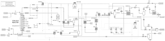
Figure 1.
Flowsheet of the combined supercritical water gasification and oxidation SCW-GcO process.
In principle, the primary feedstock could be any organic matter in solid or liquid state. In the case of municipal solid waste (MSW) the pre-treatment could be a pyrolysis unit that transforms the waste into an oily stream and a carbonaceous stream. Since for a given gasifier the admissible range of feedstock properties is narrow [19], feedstock at the gasifier could be preferably an organic waste in liquid state such as a mixture of solvents, chemicals, and oil from the chemical and processing industries. On the contrary, oxidation can support much more change to feedstock composition and can also accept solids suspended in water.
Waste in liquid state mixed with water (H-OIL-IN) is first sent to the gasification chamber of the combined reactor, where it is partially converted to a gasification reactor effluent (GAS-OUT). The conversion is almost completed in a catalytic post-gasification reactor; after a cooling section (HEX4–5) and gas–liquid separation (DEMIST2), a liquid water and oil mixture (17 L; “oil” being partially gasified organic matter whose amount depends on the gasification yield) and a hydrogen-rich syngas stream (17G) are obtained. The latter is first treated in an H2S trap and then in a methanation reactor (METHANAT) to improve CH4 yield. A second flash separation stage (DEMIST3) allows acid water (30 L) to be removed from the syngas, which is then treated in a membrane separator (STAGE1–2) to remove CO2. The liquid stream 17 L is heated in a high-pressure heat exchanger (HEX4, AUXHEX5) and is continuously fed to the oxidation chamber (WTR-RCY) together with compressed air and a secondary charge of waste (3; solid or liquid organic feedstock, or both) that has the role of producing heat. Indeed, almost all organic carbon is completely converted to CO2 (conversion yield >99.9%), producing the heat necessary to sustain gasification. The output from the oxidation reactor is cooled (HEX1–2) and separated (DEMIST1) to remove carbon dioxide, nitrogen, and other gas (23) from the liquid acid water (11L). Two cooling systems (AIRCOOL1–2) connected to heat exchangers allow heat to recover from processing the hot stream and finally are used to generate electricity in a thermoelectric generator (TEG1–2–3).
This process arrangement allows two drawbacks of gasification to be overcome:
- Since supercritical water gasification does not reach 100% efficiency (typical efficiency is between 60 and 90% depending on the feedstock), the liquid residue of gasification that is a harmful waste can be destroyed in the integrated oxidation section.
- The SCWO generates the heat that is necessary to sustain the endothermic gasification with an improvement in the heat balance of the process.
The main feature of the combined plant is that the two reactors (gasification and oxidation) are fully integrated from a chemical and thermal point of view as shown in Figure 2.
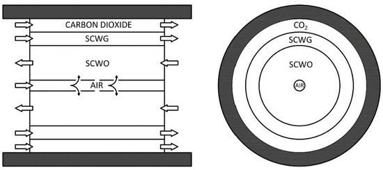
Figure 2.
Internal design of the supercritical water gasification and oxidation reactor.
The reactor behaves as a countercurrent tube in-tube heat exchanger, where hot oxidation products preheat the cold gasification input feed through the wall of thin titanium shields. The outside wall of the reactor is made of stainless steel resistant to high operating pressures. The internal volume is separated in three coaxial chambers by means of septa made in titanium to stand up to corrosion. The differential pressure between the chambers is regulated at few bars in order to use thin septa. The central chamber is used for oxidation, with air supplied by a compressor. To ensure that air reacts exclusively in the central part of the reactor and to avoid the formation of hot spots, it is introduced directly into the reaction zone through a tube with lateral holes. The adjoining area is where gasification occurs, without oxygen. The third chamber, in contact with the reactor wall, is fluxed by carbon dioxide or another gas, which acts as a cooling fluid and an inert fluid that protect the wall from corrosion. This arrangement allows for the use of stainless steel as a pressure standing shell, and not expensive special alloys, instead of Inconel.
2.2. Model and Simulation
In the following paragraph a base process scheme of SCW-GcO with a nominal capacity of 100 kg/h is presented and discussed. The process was simulated using the Aspen Plus™ package. The conceptual process design is that described in Figure 1.
As an input of the simulation, we selected heavy oil for gasification and fine carbon black for oxidation, the properties of which are reported in Table 1.

Table 1.
Characterization of the main input flow.
The main method selected to calculate the thermodynamic properties and run the simulation was the ELECNRTL (Not-Random Two-Liquids for Electrolytes), which is suitable for aqueous systems in which salt solubility and precipitation phenomena are of interest. A number of selected ionic species (e.g., sulfides, chlorides, sulfates, nitrates, carbonates) were added to the simulation through the electrolyte wizard procedure, allowing for the calculation of the pH of the reactor effluents and the simulation of the neutralization section.
A second property method, the PSRK (Predictive Soave–Redlich–Kwong), was applied to some model blocks (e.g., gas–liquid separators) to better predict the solubility of low molecular weight gases in water systems under very high pressures.
Most of the components selected from the Aspen database to be part of the simulation were defined as “conventional” (e.g., common light gases, water, hydrocarbons, ionic species), i.e., they are handled according to the selected thermodynamic methods and participates to equilibria and reactions. Some compounds were defined as “conventional inert solid” (e.g., common oxides and their hydrated variants) in order to simulate the formation of solid inert ashes in the oxidation reactor whenever metal atoms enter the system under any form or species. Metal oxides, if formed inside the reactor, were simulated to be easily separated and purged as solids from the supercritical effluent.
The heavy oil inlet stream was characterized molecularly through an arbitrary selection of 36 compounds representative of few component families (linear alkanes, cycloalkanes, branched alkanes, aromatics, polyaromatics, sulfur-containing compounds). The selection of components was guided by information retrieved from literature about the typical species and families found in low-sulfur heavy fuel oil [20,21]. The complete composition is reported in Table A1.
Similarly, the carbon black inlet stream, which may be rich in sulfur as well, was characterized assuming the arbitrary composition reported in Table 1 [22,23], where high heating values (HHV) are also reported.
In both cases, the great number of model compounds selected, even if arbitrary, gives the simulator much flexibility when solving and closing material balances in reaction blocks.
The SCW-GcO reactor was assumed to be a hierarchical block that simulated the operation of the integrated oxidation/gasification reactor in supercritical water. The internal blocks were all solved with chemistry and Henry components disabled. Within the hierarchical block, the thermal exchanges were simulated with heater/cooler blocks in which the set specification was the duty thermal or the outlet temperature as calculated by the physical–mathematical model of the reactor developed with MATLAB code. The setup of the innovative reactor is described in Figure A1 in Appendix A.
H2STRAP was a block that simulated the H2S trap with selective adsorption at high pressure (~250 atm) on iron oxides (FeO). The operation was simulated with an adiabatic and isobaric stoichiometric reactor, in which the chemical reaction H2S + FeO → FeS + H2O was specified with a conversion of hydrogen sulfide equal to 99.9999%.
STAGE-1 and STAGE-2 were blocks that simulated a membrane separation system set up with split fractions obtained from performance simulations of third-party membrane modules and lamination valves to take account of in/out pressure drops.
Although simulations were performed at various temperature and feed concentrations, we report in Table 2 data corresponding to only one set of operating conditions, with the gasification temperature set at 600 °C and oxidation temperature set at 800 °C. The input of the plant was made up of four streams: pure water at 16 kg/h (WATER-1), pure water at 14.17 kg/h (WATER-2), carbon black at 4.0 kg/h (C-BLACK), pyrolysis oil at 4.72 kg/h (HEAVYOIL), and air at 60 kg/h (AIR). The simulated output steams were gaseous products of oxidation after separation from the liquid phase (23), aqueous products of oxidation and gasification containing sulfuric and hydrochloric acid (ACIDWTR), ash formed in the oxidation and gasification sections, methane as the main product stream (CH4-OUT), and residue CO2 and H2S obtained after gas cleaning (CO2-OUT and FES).
Table 2.
Operative conditions of the SCW-GcO process streams.
2.2.1. Gasifier and Oxidizer Model
The gasification section was modeled by applying a RGIBBS block, which was able to predict the final product composition based on the principle of minimizing the total Gibbs free energy. The expected species specified in the Gibbs block consisted of major gas constituents (CO, H2, CO2, and CH4), light hydrocarbons (C2H4 and C2H6), inorganic species (HCl, H2S, N2, NH3, COS, and HCN), and tar components (C6H6, C7H8 and C10H8, and higher hydrocarbons).
The choice of a RGIBBS reactor to model the gasification reactions is supported by other previous papers by the same authors [24], where it was stated that the calculated outlet composition of the gas phase is in good agreement with experimental data obtained at a residence time in the reactor of 120 s and a mean reaction temperature of 600 °C.
The gasification efficiency, defined as
expresses the mass of gas produced in the gasification chamber with respect to the amount of organic matter fed to the reactor. It was calculated at 43.3%. The flow rate and gas compositions of produced gas are reported in Table 3. These values refer to stream 17G at the exit of the separator.
Table 3.
Compositions and flow rates of gas produced from the gasification section of the SCW-GcO plan.
The liquid stream 17 L was mainly composed of water (98 wt%), carbon dioxide (1.55 wt%), methane (0.18 wt%), hydrogen sulfide (0.18 wt%), and traces of hydrogen, carbon monoxide, and ethane.
As for the oxidation section, the efficiency was expressed as % of TOC removal from the inlet stream of organic matter, where TOC is the total organic carbon (mg/L):
The feeds were stream SLRY-IN composed of carbon black, water, and polluted water from gasification and stoichiometric air (AIR). The effluent, after cooling in two heat exchangers, was separated in a separator (DEMIST) where liquid stream 11 L and gas stream 23 were obtained. In our case study, the TOC removal was calculated as 99.3%, which is a value coherent with that measured experimentally, which typically is above 99%. Stream 23 was composed of N2 (76 wt%), CO2 (22.62 wt%), Ar (1.14 wt%), H2O (0.18 wt%), and O2 (0.01 wt%), which were discharged into the atmosphere without further post-treatments.
The oxidation section was simulated through a separate RGibbs reactor in which the expected outlet species were exclusively H2O and CO2 as the main oxidation products; inorganic acids such as HCl, H2SO4, and HNO3 (involved in aqueous salt equilibria in downstream equipment); and inert solid metal oxides that were easily separated. Sulfur and nitrogen oxides were not included among the outflow species, as they were not expected in the dry gaseous fraction of the effluent, as confirmed by the literature [10].
2.2.2. Life Cycle Assessment
The goals of this work were the evaluation of the energy–environmental performance and the identification of the hot spots in the SCW-GcO process, compared to conventional incineration processes of dangerous waste, solvent mixtures, and exhaust oils. Analysis was carried out according to a “cradle to gate” approach: from the extraction of raw materials to the production of methane derived from the treatment of waste. The supply chain of the waste to be treated was neglected, such as leachate, carbon black, heavy oil, and the plant start-up phase. Looking at the entire useful life, considered to be 10 years, in terms of environmental impact the start-up phase was negligible. The end-of-life and disposal phases of the plant were also not taken into consideration. In fact, since the object of study was a pilot system in the construction phase, the results obtained referring to this phase would be characterized by a high uncertainty and would therefore be unreliable. Two cases were examined:
- In the first (Case 1) the co-production of methane was not considered; and
- In the second (Case 2) the avoided impact associated with this valuable product was quantified.
By avoided impact we mean that the methane produced decreased the consumption of natural gas from fossil sources used for feeding the end-user distribution network. This benefit associated with the production of methane was appreciated exclusively during use. During production this had no influence on energy consumption or the environmental impacts assessed. The functional unit (FU) of reference for the LCA was 1 ton of treated waste: carbon black, heavy oil, and leachate. System boundaries (SB) determined the process units to be included within the evaluated system. The system boundaries set for the LCA of SCW-GcO are shown in Figure 3. In Case 2, the boundaries were extended to a power plant for electricity production using methane.
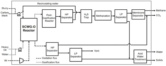
Figure 3.
Life cycle flowchart of the overall system.
The mass and type of materials required for assembly was quantified for each component. Construction processes of the innovative reactors were analyzed in detail, considering the amount of energy used for assembly and processing of materials. For the working phase we referred to a useful life of 10 years and it was assumed that a working year consisted of 8000 h. Mass and energy flows (in and out) from this period of time were then quantified.
Auxiliary inputs for catalyzer components (catalytic post-gasifier and methanation reactor), the H2S trap, and acid water treatment were not considered because they were negligible compared to the main in/out currents. The energy consumption of pumps, compressors, and inverters was assumed considering rated powers and corrected with coefficients related to the working phase.
3. Results and Discussion
Before analyzing the environmental impact, energy consumptions were examined. These concerned the production phase and working phase of the pilot plant. In terms of what concerned the production of components, the reactors required the highest energy consumption, as show in Figure 4. They were non-commercial components custom made for the pilot plant. Most of this energy was of a non-renewable (NR) fossil nature with 342.89 GJ and NR nuclear with 49.71 GJ. Renewable (R) resources contributed with biomass (2.48 GJ), wind/solar/geothermal (1.07 GJ), and water (42.39 GJ).
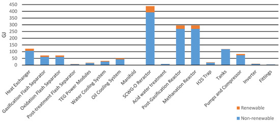
Figure 4.
Primary energy for the production of the components.
Concerning the working phase analyzed with Aspen Plus for the treatment of 1 ton of waste (0.16 tons of carbon black, 0.19 tons of heavy oil, and 0.65 tons of leachate), an energy consumption of 1.1 GJ was estimated, as shown in Figure 5. The utilities involved were pumps, compressors, and an inverter. Methane produced from gasification can generate 7.3 GJ given an HHV of 55 MJ/kg and a production of 133.54 kg. Therefore, an estimated energy balance had a surplus of 6.25 GJ.
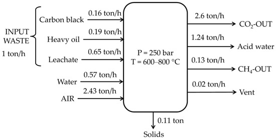
Figure 5.
Mass balance of the SCW-GcO system.
In Figure 6a comparison between primary energy consumptions for the working phase is represented. It appears clear how methane recovered in Case 2 had a large influence on energy generated from fossil resources, with a 7.3 GJ/ton reduction of primary energy impacts from fossil resources.
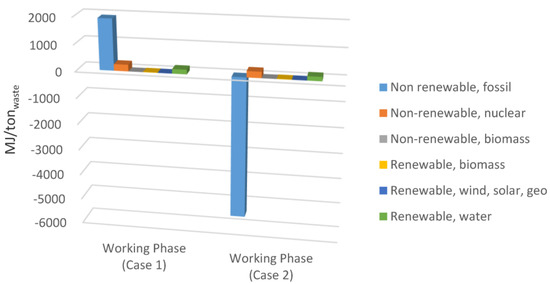
Figure 6.
Comparison of the primary energy consumption for Case 1 and Case 2 (working phase).
Figure 7 shows the environmental impact of the working phase. Methane production has positive effect, especially on land use and ozone depletion, which had negative values due to natural gas saved and reduced emissions.
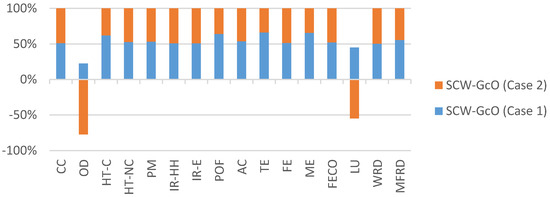
Figure 7.
Comparison of the environmental impacts for Case 1 and Case 2 (working phase). Acronyms are reported in Table 4.
For the production phase, the environmental impacts of all components were analyzed and Table 4 summarizes those with the highest impacts for all categories. The unconventional and non-commercial nature of reactors and heat exchangers led them to be the most impactful elements of the plant.
Table 4.
Components with the highest environmental impact (production phase).
The novel process was compared with typical hazardous waste incinerators (HWI) for the treatment of dangerous wastes, solvent mixtures, and exhaust oils (Table 5). A model HWI with a wet flue gas scrubber and low-dust SCR DeNOx facility was considered. A gross thermal efficiency of 74.4% and gross electric efficiency of 10% were considered. In Figure 8a comparison of the primary energy consumption for incineration and SCW-GcO is shown. The good performance especially for SCW-GcO (Case 2) with methane recovery is worth noting.
Table 5.
Output stream descriptions (Ecoinvent v3.5 database).
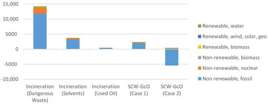
Figure 8.
Comparison of the primary energy consumption between the incineration processes and SCW-GcO (working phase).
In particular, treatment of dangerous wastes with the SCW-GcO process had less impact in every category, as shown in Figure 9, where a comparison of the environmental impacts between the two methods is reported. As far as the incineration of solvent mixtures is concerned, the combined process had a higher impact in AC due to a greater production of acid water and in WRD due to a higher consumption of water for the dilution of input streams. A comparison of the environmental impact between SCW-GcO and the incineration of exhaust oils shows that there was no best process between them. Only in two categories were impacts comparable; in other cases one process was better than the other. The choice must be made by evaluating the importance of each impact category; however, as shown previously, energy consumption is favorable for SCW-GcO (Case 2) thanks to methane recovery.
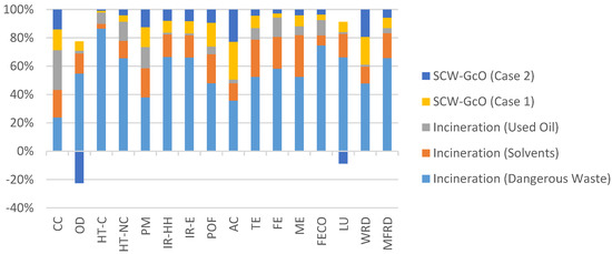
Figure 9.
Comparison of the environmental impacts between the incineration processes and SCW-GcO (working phase).
4. Conclusions
In this study, a new integrated process based on supercritical water gasification and oxidation (SCW-GcO), was proposed. Process simulation allowed for the evaluation of mass and energy balance and the composition of output streams. It was shown that solid and liquid waste can be effectively treated without the production of wastewater or noxious gas emissions. The process is also able to produce methane as a valuable product at a mass rate of 13% with respect to the input waste, with an energy surplus of 6.25 GJ per ton of treated waste.
It was also investigated whether the innovative SCW-GcO process could be a viable alternative to the incineration of hazardous wastes. LCA applied to SCW-GcO shows that the option including methane recovery (Case 2) is a better choice than incineration, thanks to its minor environmental impact and lower energy consumption in most of the scenario analyzed. A return period of 4.3 years was also estimated. The return period was assessed as the time required for the initial impact, in terms of the energy consumption associated with production and use, to be recovered due to the production of methane. These conclusions seem promising and pose the basis to begin a scale-up of the process.
5. Patents
SCW-GcO is a new process that was designed and simulated in the framework of the research program Moterg-Bio, financed by the Italian Minister of Industrial Development (MISE). This work was supported by Archimede S.r.l. Società di Ingegneria, Caltanissetta (Italy), and financed by the Italian Minister of Industrial Development (MISE). SCW-GcO has been patented: international patent request number PCT/IB2016/052044, international publication number WO 2016/166650 Al [25].
Author Contributions
Conceptualization, F.S. and G.C.; methodology, S.L.; software, P.I.; validation, S.L.; investigation, P.I.; data curation, P.I.; writing—original draft preparation, P.I.; writing—review and editing, G.C.; supervision, M.C. and A.B., funding acquisition, G.C. All authors have read and agreed to the published version of the manuscript.
Funding
This research was funded by Biofeedstock project, PNR 2015–2020, Ministero dell’Istruzione dell’Università e della Ricerca, grant number ARS01_00985.
Institutional Review Board Statement
Not applicable.
Informed Consent Statement
Not applicable.
Data Availability Statement
The data presented in this study are available on request from the corresponding author. The data are not publicly available due to non-disclosure agreement about involved patent.
Conflicts of Interest
The authors declare no conflict of interest.
Appendix A

Figure A1.
Sub-flowsheet of the SCW-GcO reactor from Aspen Plus.
Figure A1.
Sub-flowsheet of the SCW-GcO reactor from Aspen Plus.

Table A1.
Heavy oil composition.
Table A1.
Heavy oil composition.
| Heavy Oil Composition [%weight] | |||
|---|---|---|---|
| Naphthalene | 12.0% | Diphenyl | 2.0% |
| Ethylbenzene | 6.6% | Acenaphthene | 1.8% |
| Cyclohexane | 5.7% | Fluorne | 1.2% |
| Cyclopentane | 5.4% | Benzothiophene | 1.1% |
| Benzene | 4.7% | Phenanthrene | 1.0% |
| 2,3-Dimethylpentane | 4.5% | 1,2-ethanedithiol | 1.0% |
| 2-Methylhexane | 4.4% | Thiophene | 1.0% |
| 2,2-Dimethylpentane | 4.4% | 3-methylthiophene | 0.9% |
| 2,4-dimethylpentane | 4.4% | 2-methylthiophene | 0.9% |
| 3-methyl-pentane | 4.3% | Diethyl-disulfide | 0.9% |
| Bicyclo-2-2-1-heptane | 4.3% | Acenaphthalene | 0.8% |
| N-hexane | 4.3% | Dimethyl-sulfide | 0.8% |
| 2-methyl-pentane | 4.3% | Methyl-ethyl-sulfide | 0.8% |
| N-pentane | 4.1% | methyl-n-propyl-sulfide | 0.8% |
| 1,2-diphenylethane | 2.3% | Methyl-t-pentyl-sulfide | 0.8% |
| 3-ethylpentane | 2.2% | 1-pentanethiol | 0.8% |
| 3,3-dimethylpentane | 2.2% | 2-pentanethiol | 0.7% |
| 3-methylhexane | 2.1% | Methyl-t-butyl-sulfide | 0.7% |
References
- National Research Council. Waste Incineration and Public Health; National Academic Press: Washington, DC, USA, 2000; ISBN 9780309063715. [Google Scholar]
- Brunner, G. Near critical and supercritical water. Part I. Hydrolytic and hydrothermal processes. J. Supercrit. Fluids 2009, 47, 373–381. [Google Scholar] [CrossRef]
- Guan, Q.; Wei, C.; Savage, P.E. Kinetic model for supercritical water gasification of algae. Phys. Chem. Chem. Phys. 2012, 14, 3140–3147. [Google Scholar] [CrossRef] [PubMed]
- Guo, Y.; Wang, S.Z.; Xu, D.H.; Gong, Y.M.; Ma, H.H.; Tang, X.Y. Review of catalytic supercritical water gasification for hydrogen production from biomass. Renew. Sustain. Energy Rev. 2010, 14, 334–343. [Google Scholar] [CrossRef]
- Reddy, S.N.; Nanda, S.; Dalai, A.K.; Kozinski, J.A. Supercritical water gasification of biomass for hydrogen production. Int. J. Hydrog. Energy 2014, 39, 6912–6926. [Google Scholar] [CrossRef]
- Kruse, A. Supercritical water gasification. Biofuels Bioprod. Biorefining 2008, 2, 415–437. [Google Scholar] [CrossRef]
- Cherad, R.; Onwudili, J.A.; Biller, P.; Williams, P.T.; Ross, A.B. Hydrogen production from the catalytic supercritical water gasification of process water generated from hydrothermal liquefaction of microalgae. Fuel 2016, 166, 24–28. [Google Scholar] [CrossRef]
- Bermejo, M.D.; Cocero, M.J. Supercritical water oxidation: A technical review. AIChE J. 2006, 52, 3933–3951. [Google Scholar] [CrossRef]
- Vadillo, V.; Sánchez-Oneto, J.; Portela, J.R.; De La Ossa, E.J.M. Problems in supercritical water oxidation process and proposed solutions. Ind. Eng. Chem. Res. 2013, 52, 7617–7629. [Google Scholar] [CrossRef]
- Brunner, G. Hydrothermal and Supercritical Water Processes (Supercritical Fluid Science and Technology—Volume 5); Elsevier: Amsterdam, The Netherlands, 2014; ISBN 9780444594136. [Google Scholar]
- Cocero, M.J.; Alonso, E.; Sanz, M.T.; Fdz-Polanco, F. Supercritical water oxidation process under energetically self-sufficient operation. J. Supercrit. Fluids 2002, 24, 37–46. [Google Scholar] [CrossRef]
- CHANG, S.; Liu, Y. Degradation mechanism of 2,4,6-trinitrotoluene in supercritical water oxidation. J. Environ. Sci. 2007, 19, 1430–1435. [Google Scholar] [CrossRef]
- Marrone, P.A. Supercritical water oxidation—Current status of full-scale commercial activity for waste destruction. J. Supercrit. Fluids 2013, 79, 283–288. [Google Scholar] [CrossRef]
- Shaw, R.W.; Dahmen, N. Destruction of toxic organic materials using super-critical water oxidation: Current state of the technology. Supercrit. Fluids 2000, 425–437. [Google Scholar] [CrossRef]
- Qian, L.; Wang, S.; Xu, D.; Guo, Y.; Tang, X.; Wang, L. Treatment of sewage sludge in supercritical water and evaluation of the combined process of supercritical water gasification and oxidation. Bioresour. Technol. 2015, 176, 218–224. [Google Scholar] [CrossRef] [PubMed]
- Portela Miguelez, J.R.; Sanchez Oneto, J.; de la Ossa Fernandez, E.J.M.; Garcia Jarana, M.B.; Casademont Lanzat, P. Integrated Oxidation and Gasification of Aqueous Organic Waste in Supercritical Water (WO 2018/065641 A1) 2018. Available online: https://patentscope.wipo.int/search/es/detail.jsf?docId=WO2018065641 (accessed on 20 December 2020).
- Wang, Y.; Wang, S.; Guo, Y.; Xu, D.; Gong, Y.; Yu, G.; Yu, H. Supercritical water oxidation of lurgi coal gasification wastewater and evaluation of the combined process with gasification. Adv. Mater. Res. 2013, 610–613, 2203–2210. [Google Scholar] [CrossRef]
- Wang, Y.Z.; Wang, S.Z.; Guo, Y.; Xu, D.H. Evaluation of the combined process of aammonia distillation-evaporation concentration—Supercritical water gasification - supercritical water oxidation for coking wastewater treatment. Adv. Mater. Res. 2013, 763, 191–194. [Google Scholar] [CrossRef]
- Consonni, S.; Viganò, F. Waste gasification vs. conventional Waste-To-Energy: A comparative evaluation of two commercial technologies. Waste Manag. 2012, 32, 653–666. [Google Scholar] [CrossRef] [PubMed]
- Han, Y.; Zhang, Y.; Xu, C.; Hsu, C.S. Molecular characterization of sulfur-containing compounds in petroleum. Fuel 2018, 221, 144–158. [Google Scholar] [CrossRef]
- Daling, P.S.; Cooper, D.; Buist, I.; Faksness, L.; Altin, D.; Pettersen, T.; Bakken, O.M. Characterization of Low Sulfur Fuel Oils (LSFO)—A New Generation of Marine Fuel Oils; SINTEF: Trondheim, Norway, 2020. [Google Scholar]
- International Agency for Research on Cancer. Polynuclear Aromatic Hydrocarbons, Part 2, Carbon Blacks, Mineral Oils (Lubricant Base Oils and Derived Products) and Some Nitroarenes; IARC Working Group on the Evaluation of Carcinogenic Risks to Humans: France, 1984; 33, ISBN 9283212339. Available online: https://pubmed.ncbi.nlm.nih.gov/6590450/ (accessed on 20 December 2020).
- International Agency for Research on Cancer. Some Non-Heterocyclic Polycyclic Aromatic Hydrocarbons and Some Related Exposures; IARC Working Group on the Evaluation of Carcinogenic Risks to Humans: France, 2010; 93. Available online: https://www.ncbi.nlm.nih.gov/books/NBK321712/ (accessed on 20 December 2020).
- Caputo, G.; Rubio, P.; Scargiali, F.; Marotta, G.; Brucato, A. Experimental and fluid dynamic study of continuous supercritical water gasification of glucose. J. Supercrit. Fluids 2016, 107, 450–461. [Google Scholar] [CrossRef]
- Brucato, A.; Caputo, G.; Grisafi, F.; Scargiali, F.; Tumminelli, G.; Tuzzolino, G.; D’Agostino, R.; Rizzo, R. Plant for waste disposal and associated method (WO 2016/166650 Al) 2016, 39. Available online: https://iris.unipa.it/retrieve/handle/10447/219751/395225/Brevetto_WO2016166650%28A1%29.pdf (accessed on 20 December 2020).


Publisher’s Note: MDPI stays neutral with regard to jurisdictional claims in published maps and institutional affiliations. |
© 2020 by the authors. Licensee MDPI, Basel, Switzerland. This article is an open access article distributed under the terms and conditions of the Creative Commons Attribution (CC BY) license (http://creativecommons.org/licenses/by/4.0/).