Article

Analysis of EMG Electrode Locations Using 3D Body Scanning for Digital Pattern Construction of a Smart EMG Suit

1
Human Convergence Technology R&D Department, Korea Institute of Industrial Technology, Ansan-si 15588, Gyeonggi-do, Korea
2
Department of Fashion Industry, Ewha Womans University, Seoul 03760, Korea
*
Author to whom correspondence should be addressed.
These authors contributed equally to this work.
Sustainability 2021, 13(5), 2654; https://doi.org/10.3390/su13052654
Submission received: 23 December 2020 / Revised: 9 February 2021 / Accepted: 23 February 2021 / Published: 2 March 2021
(This article belongs to the Special Issue Sportwear in the Next Normal: Product Development and Marketing)

Abstract

:
According to recent trends, smart clothing products that can receive electromyography (EMG) signals during the wearer’s muscle activity are being developed and commercialized. On the other hand, there is a lack of knowledge on the way to specify the electrode locations on the clothing pattern. Accurately located EMG electrodes in the clothing support the reliability and usefulness of the products. Moreover, a systematic process to construct anatomically validated smart clothing digitally should be performed to facilitate the application of a mass-customized manufacturing system. The current study explored the EMG measurement locations of nine muscles and analyzed them in association with various anthropometric points and even postures based on the 3D body scan data. The results suggest that several line segments of the patterns can be substituted by size-dependent equations for the electrodes in place. As a final step, a customized pattern of a smart EMG suit was developed virtually. The current study proposes a methodology to develop body-size dependent equations and patterns of a smart EMG suit with well-located electrodes using 3D scan data. These results suggest ways to produce smart EMG suits in response to impending automation and mass customization of the clothing manufacturing system.

1. Introduction

With the development of wearable technology, the market for smart wearable products in conjunction with information and communications technologies (ICT) is expanding rapidly [1,2,3]. Several products providing refined information based on real-time bio-signal measurements are being commercialized. The interest in smart clothing measuring electromyography (EMG) has increased with the expectations of broad applications from self-fitness training to rehabilitation exercise aids. EMG is an electrical inspection technique that detects, amplifies, records, and analyzes the electric potential difference caused by muscle contraction and relaxation with electrodes by quantifying the degree of muscle contraction [4]. Smart wearable products that can provide EMG measurements are composed of electrodes embedded into clothing that can provide users’ real-time muscle activity without complex instrumentation [5,6,7].
The accuracy of EMG measurements is one of the key performances that cannot be ignored when providing appropriate information and feedback to users. On the other hand, the application of EMG techniques to smart clothing is challenging due to technical hurdles related to EMG acquisition and clothing construction. Initially, EMG noise can be generated for various reasons, such as motion artifacts and unstable electrode–skin contact area. EMG is vulnerable to contamination by noise, which makes valid EMG signals difficult to extract. In addition, EMG signals are less standardized than those of an electrocardiogram (ECG), so that the filtering process is too sophisticated to remove noise and keep valid EMG signals unimpaired. Moreover, both inappropriate electrode locations and larger electrodes are associated with the crosstalk problem in EMG between the adjacent recording sites [8]. Some commercial products and prototypes use a larger skin contact area of the sensor [7,9], but they are good for recreational use, not for clinical use in that smaller muscles can be monitored where the crosstalk of EMG often occurs [8]. An excessive low-pass filtering problem has been reported for large electrodes [10]. Finally, the form and size of muscles are varied by individuals; thus, ready-made clothes have a limitation to provide well-located electrodes for their each muscle. Generally, manual palpation for each muscle is recommended for EMG electrode placement, which cannot be applied to clothing embedded with EMG electrodes. Electrodes attached in place are essential requirements to obtain valid and valuable EMG signals from a smart EMG suit.
Several studies have been done so far with regard to smart EMG clothing. Frequently visited topics include the development and analysis of the textile-based EMG electrodes [6,7], validity test of the commercial products [5,11], location and arrangement of EMG electrodes [12,13], and optimization of electrode sizes or clothing pressure [14,15]. On the other hand, there have been few attempts for pattern making of EMG suits and EMG electrodes for mass customization. Lee [13] examined the shape and arrangement of EMG electrodes for arm and leg muscles, and Cho and Cho [12] studied EMG sensing positions that can be applied to EMG suits, but neither approached the pattern making of EMG suits particularly considering the relationship between EMG electrodes and anthropometric data to solve a problem of individual differences in muscle formation and body size.
Pattern development of EMG clothing based on individual body size parameters is a fundamental step in realizing mass customized smart clothing [16,17]. In particular, in a mass customization process of EMG suits, by simply inputting certain body size parameters (e.g., height and chest circumferences), the EMG electrode locations can be estimated, and a final clothing pattern, including EMG electrodes, will be obtained. In this system, some of the key technologies are the proper placement of electrodes on clothing and the development of valid clothing patterns and manufacturing clothing using little individual information. Smart wearable products in clothing types could be popularized through automated mass customization, considering the higher price and lack of accuracy, which are often mentioned as the current limitations [18].
Therefore, in this study, the primary research task was to establish a digital pattern construction process of EMG suits based on individual body size parameters. This also highlighted an exploration of potential line segments in patterns, which can be size-dependently designed. Figure 1 presents an overview of the conceptual and structural framework of the current study. In the first step, 3D body scans and manual measurements were carried out to obtain body size data. The 3D body scan was used to extract the distances between the EMG electrode attachment points (EP) and anthropometric landmarks (AP). The distances between the EP and AP were analyzed with relevance to body size parameters, which are commonly used in drawing patterns or selecting the garment size. The effects of the body postures on the EP to AP distance were also investigated to verify the necessity of designing patterns for dynamic postures as a preparatory study. Finally, an example of a digital clothing pattern for EMG suits was drawn. The entire processes suggested are toward developing an automated manufacturing system for mass customized smart EMG suits.

2. Methods

2.1. Subjects

For this preliminary study, five males were recruited in the 3D scanning procedures (age = 30 ± 4 years; body weight = 72.6 ± 7.0 kg; height = 179.1 ± 2.8 cm; body fat = 15.4 ± 5.4%; chest circumference = 96.9 ± 4.8 cm). Each subject was informed of the entire experimental procedures and signed an informed consent form before participation. All procedures were approved by the Public Institutional Review Board designated by the Ministry of Health and Welfare (##IRB No.P01-202005-23-002).

2.2. 3D Body Scanning Protocol

The 3D body scanning was conducted in the following order. (1) The subjects changed their clothing to tight-fit shorts, which were a tight-fit but not compressive so that their body silhouettes were barely distorted. (2) The landmarks, which need to be collected through 3D body image, were attached to the right side of the body with arrow-shaped stickers. The landmarks included 28 anthropometric points (AP) and nine EMG electrode attachment points (EP) (see more in Section 2.3). (3) Each subject was scanned in four body postures (see more in Section 2.4). Scanning was performed using a handheld 3D scanner (Artec Eva 3D scanner, Artec Group, Luxembourg, Luxembourg). The researcher scanned the subject’s whole body by rotating 360° around the subject. The body scan was conducted 3–4 times for each body posture. To maintain the stability of the posture, 5–10 min of rest was allowed between each scanning trial. Before each scanning, all markers were re-inspected to determine if they are in the correct location. The entire scanning protocol for four postures, except for preparation, took approximately 1.5–2 h for each subject.

2.3. Landmarks: Anthropometric Points (AP) and EMG Electrode Attachment Points (EP)

Twenty-eight APs closely related to pattern making were marked on the right side of the body (Figure 2). The procedures and location of the landmarks followed the recommendation of Lu and Wang [19], Size Korea [20], and ISO 8559-1 [21]. The bust point and the crotch were included in the APs, but digitally marked on the acquired 3D image instead of directly marking on the subject’s body.
Nine EPs were mainly selected among the muscles, which are of interest for fitness training and those located near the skin so that surface EMG of those muscles can be obtained easily (Figure 2): middle deltoid (MD), biceps brachii (BB), upper trapezius (UT), pectoralis major (PM), latissimus dorsi (LD) gluteus maximus (GM), rectus femoris (RF), biceps femoris (BF), and adductor magnus (AM). The EPs of each muscle were identified based on the recommendation of previous studies [22,23,24,25,26,27,28,29]. The UT marker was applied on the muscle belly of the muscle group with a palpation [22]. The MD marker was placed midway between the acromion and deltoid tubercle [23]. The BB marker was placed on the central point of the most protruding upper arm when the arm was bent [23]. The PM marker was applied as a four-finger-width under the clavicle and medial to the anterior axillary border [24]. The LD marker was located approximately 4 cm below the lower end of the scapula and midway between the spine and the lateral edge of the torso [25]. Regarding the muscles on the lower body, the GM marker was placed midway between the greater trochanter and the mid sacral vertebra, at the level of the trochanter [26]. The RF was on the mid-point of the line joining the anterior superior iliac spine and the superior patellar pole [27]. The AM was applied midway between the pubic tubercle and the medial femoral epicondyle over the bulk of the adductor muscles [28]. Finally, the BF marker was midway between the ischial tuberosity and tibial epicondyles [29]. Manual palpation was also carried out during the entire preparation procedures.

2.4. 3D Body Scan Postures

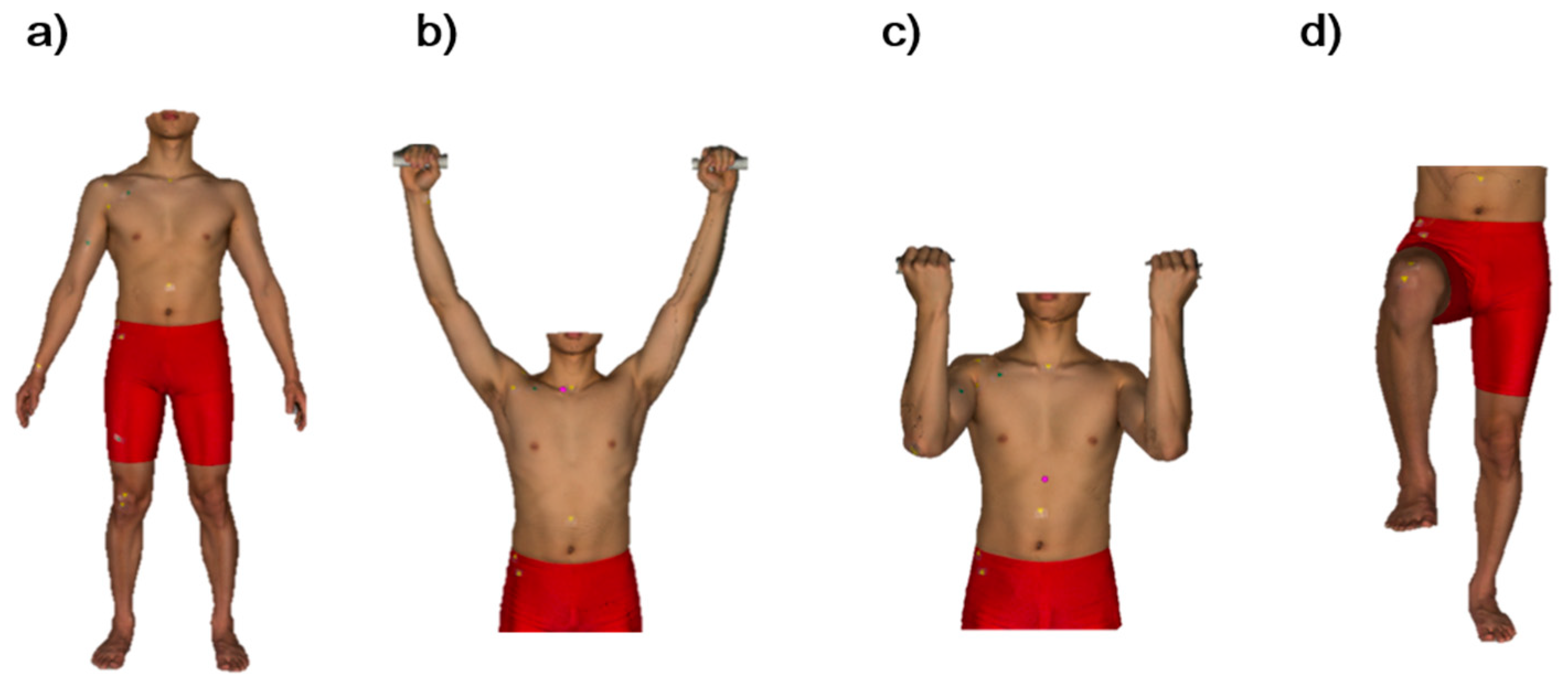
After the EPs and APs were placed manually, each body posture was scanned. Four postures were selected, including a standard static standing posture and three dynamic postures (Figure 3). In the static posture, the subject stood with their legs shoulder-width apart, and their arms were placed 20° apart from the body (Figure 3a). In the first dynamic postures, subjects raised both arms vertically and kept the distance at 1.6 times the shoulder-width while standing upright (Figure 3b). In this posture, the subject was instructed to minimize the shoulder elevation. In the second dynamic posture, the subjects stretched their upper arms forward and bent their forearms at 90° (Figure 3c). They kept their forearms parallel with a shoulder-width distance. A compression rod was used to maintain the stability of their arm posture in both dynamic postures. Finally, the subjects placed their left foot on the floor and their right foot on a height-adjustable box to make 90° knee flexion (Figure 3d). The subjects held a four-legged cane to stand stably.

2.5. Manual Measurement for the Body Size Parameters

Manual measurements were carried out for the height, waist back length, shoulder length, chest circumference, and waist circumference according to the method specified by ISO 8559-1 [21]. They were selected from the body size parameters commonly used in pattern making and selecting the individual garment size.

2.6. Data Analysis

The 3D scan images were aligned using Artec Studio 14 software (Artec Group, Luxembourg, Luxembourg). Subsequently, the distances between AP and EP were measured using Geomagic Design X TM (3D systems Inc., Rock Hill, SC, USA). The Geomagic Design X TM software was originally a tool for reverse engineering for producing CAD files from 3D scan data. This program was used to analyze 3D body scan data to extract the body size, and the validity was partly verified [30]. In the current study, the program was used to extract the distances between EP and AP (see Section 2.5). In some cases, the shortest distances on the body surface between the EP and anthropometric lines were also measured (Table 1). To obtain precise data, wrinkled or rough surfaces in 3D scan images were smoothed before every distance measurement. Furthermore, the sagging clothes of the groin were removed gently to approach the crotch points. For statistical analysis, the differences by postures were tested using a Kruskal–Wallis test with the Wilcoxon test as a post hoc test. Initially, the Spearman correlation test was conducted between the EP to AP distances and the relevant body size parameters to examine the possibility of generating a body size-dependent pattern making strategy (Table 1). All possible pairs were tested for the correlation. For example, 12 correlation tests were carried out for the UT (three distances to anthropometric landmarks and lines by four body size parameters, as shown in Table 1). The results are expressed as the Spearman correlation coefficient ( ρ ). The SPSS 21.0 for windows statistical program was used for overall statistical analyses. The significance was set to p < 0.05, but the significance level was set to p < 0.1 for the Spearman correlation test results.

2.7. Pattern Making

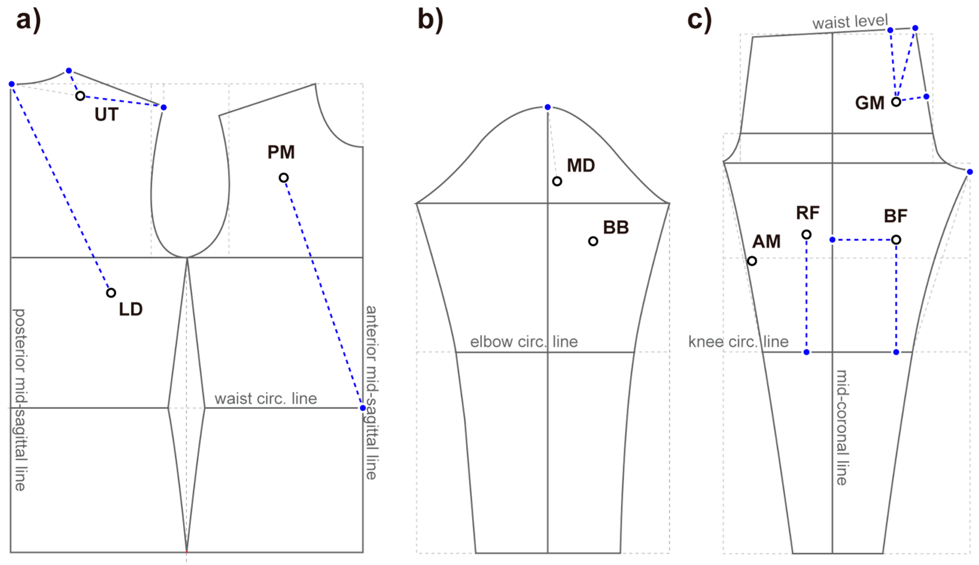
An example of an EMG clothing pattern was formed based on a subject’s body size (height = 180 cm, chest circumference = 97.5 cm, waist circumference = 80 cm, hip circumference = 96 cm, knee circumference = 40 cm, and ankle circumference = 22 cm) (Figure 4a). The basic patterns of the bodice, sleeve, and pants were obtained from Kim and Ha [31] and Jeong [32]. The circumference-related items (e.g., chest line in the bodice) were designed without any ease, and height-related items (e.g., back length, scye depth, and pants length) were designed through a calculation using the height [31,32]. Patterns were designed using the YUKA CAD pattern-making program (Yuka & Alpha Co., Ltd., Tokyo, Japan). They were fitted virtually to an avatar represented in the CLO 3D in a subject’s body size (CLO 3D version 5.2., CLO Virtual Fashion Inc., Seoul, Korea) (Figure 4b). Each EP was marked on the patterns, so the 2D clothing patterns with EPs placed can be acquired (Figure 4c).

3. Results

3.1. Distance from AP to EP in a Standard Standing Posture and Changes by Dynamic Postures

Thirty-three items were collected for the distance from the EP to AP: 16 for the upper body (trunk), 3 for the sleeves, and 14 for the lower body. The distances from the EP to AP of the upper body showed significant differences by postures (Figure 5). Figure 5 shows representative results. Those from UT to the back neck was significantly different by postures while presenting 9.67 ± 0.62 cm during standing, 7.55 ± 0.62 cm during arm raise, and 9.35 ± 0.80 cm in elbow flexion (p < 0.05). Similarly, the length from UT to the lateral shoulder point also prominently decreased from 13.35 ± 0.98 cm (standing) to 7.79 ± 0.55 cm (arm raise) (p < 0.01). On the other hand, the distances from UT to the lateral neck point was barely changed by the posture (p > 0.05): 3.98 ± 0.72 cm (standing), 4.19 ± 0.81 cm (arm raise), and 4.02 ± 0.43 cm (elbow flexion). Regarding MD, the distance to the lateral shoulder point was 9.71 ± 1.24 cm (standing), 6.63 ± 1.03 cm (arm raise), and 9.21 ± 1.15 cm (elbow flexion), with a significant difference between the standing and arm raise positions (p < 0.05). In the BB, the distance to the lateral shoulder decreased significantly from 20.85 ± 0.81 cm (standing) to 14.71 ± 1.09 cm (arm raise) (p < 0.01). In the case of the PM, the distance to the front neck was 12.13 ± 1.01 cm (standing), 8.99 ± 0.59 cm (arm raise), 10.86 ± 0.84 cm (elbow flexion), with a significant difference between the standing and arm raise positions, whereas no statistical difference was found in the distance to the lateral shoulder (p > 0.05): 12.16 ± 0.88 cm (standing), 13.56 ± 1.00 cm (arm raise), and 12.53 ± 0.82 cm (elbow flexion). In contrast, the distance to the front waist was increased substantially from 31.46 ± 0.47 cm (standing) to 37.27 ± 1.17 cm (arm raise) (p < 0.01). The average distance from the LD to the back neck decreased from 30.46 ± 1.18 cm (standing) to 29.68 ± 1.43 cm (arm raise). Furthermore, the distance from LD to the side waist marginally increased from 16.61 ± 2.93 cm (standing) to 17.05 ± 3.01 cm (arm raise), and no statistical difference was found.
On the other hand, no significant difference in postures was observed in the 14 items in the lower body except for the RF to the knee circ. line (standing: 21.65 ± 2.38; knee flexion: 31.41 ± 3.13, p > 0.05). Some representative results without differences by postures are as follows: GM to back waist (standing: 22.11 ± 5.95; knee flexion: 24.09 ± 1.57, p > 0.05); and AM to crotch (standing: 16.66 ± 4.33; knee flexion: 19.69 ± 2.35, p > 0.05).

3.2. Relationship between EP and Body Size Parameters

The Spearman correlation test between all possible pairs of the distance of EP to AP and relevant body size parameters revealed several significant correlations (Table 2). Among the body size parameters, height was correlated most frequently with the EP to AP distances: UT to the side neck ( ρ = −0.821, p < 0.1); PM to the front waist (omphalion) ( ρ = 0.975, p < 0.05); GM to the back waist ( ρ = 0.975, p < 0.01); GM to the waist line, back waist (omphalion), and mid-sagittal line (all ρ = 0.821, p < 0.1); RF to the knee line ( ρ = 0.975, p < 0.05); AM to the midpatella ( ρ = −0.821, p = 0.089); and BF to the mid-coronal line ( ρ = −0.821, p = 0.089). The shoulder length was correlated significantly with the UT to the shoulder ( ρ = 0.900, p < 0.05). The chest circumference was significantly correlated with the PM to front waist ( ρ = −0.900, p < 0.05). The back length was correlated significantly with the LD to back neck ( ρ = −0.900, p < 0.05). The waist circumference was correlated with the BF to the midpatella ( ρ = −0.900, p < 0.05). None of the EP and AP distances presented in the sleeve showed a correlation with the body size parameters (height, arm length, and chest circumference).
To specify the relative electrode location of UT between adjacent anthropometric landmarks, the ratio of “UT to the back neck” to “UT to the lateral shoulder” was calculated. The average was 0.73 ± 0.06. Among all measured body size parameters, the shoulder length only showed a significant Spearman correlation coefficient with the ratio ( ρ = −0.900, p < 0.05, Figure 6).

3.3. Specifying the EMG Electrodes’ Location on Clothing Pattern

The preliminary results of the patterns including EMG electrodes are shown in Figure 7. This is an example of the basic patterns for the made-to-measure EMG suits, as shown in Figure 7. Lines that can be drawn from body-size-dependent equations are highlighted in the blue dotted line. For example, the electrode location of UT can be specified on the line connecting the back neck and lateral shoulder (Figure 7a), as documented in Section 3.2. Transformation can be given to this basic pattern to provide an improved fit, functionality, and aesthetic impression.

4. Discussion

4.1. Overview of the Results

The current study assessed a clothing pattern design method of smart EMG suits, which is a promising research area to apply the production of smart clothing to a mass-customized manufacturing system. This study first showed that the locations of EPs in the upper body are less stable against the dynamic body postures than those of the lower body. In particular, the arm raise postures significantly decreased the distance between UT to the back neck and lateral shoulder, PM to the front neck and lateral shoulder, and BB and MD to the lateral shoulder (Figure 5). The PM to waist front was increased by arm raises. Interestingly, the distance related to LD was less vulnerable to dynamic postures than the others. Second, the current study carefully explored the potential line segments of patterns, which can be designed size-dependently. The results show that UT, PM, LD, GM, RF, AM, and BF could be designed size-dependently using common body size parameters, such as height, shoulder length, chest circumference, back length, and waist circumference (Table 2). Only MD and BB in the sleeve pattern were not identified in the correlation with the body size parameters. The APs used to measure the distances with EPs are the general reference points in clothing pattern making. Moreover, a size-dependent design strategy is essential for producing made-to-measure clothing in a mass customization system. For this reason, the pairs with a significant correlation should be revisited to develop substantive equations that can be used in pattern design. Finally, an example of a clothing pattern, including the EMG electrode location, was suggested. Basic patterns can be applied in various clothing patterns through a transformation. This topic is discussed in the next section.

4.2. Pattern Development including the EMG Electrodes

To draw EMG electrode-combined patterns, this study attempted to identify the possible approach to specific electrode locations based on basic 2D patterns. This is a relatively traditional way compared to the other methods using 3D scan data. The representative one is the surface flattening methods based on triangle meshes [33,34]. This method uses 3D body scans directly and can easily reflect the individual’s body shape characteristics, such as curvatures and shoulder slope. Its applicability to mass customization has also been suggested [35]. On the other hand, considering that it is a difficult task to obtain 3D scan data from all consumers, the current approach that can work without wearers’ 3D body scan data can be a meaningful compromise and alternative. To validate this method, lines that showed a significant correlation with the body size parameters in Table 2 should be revisited soon to develop substantive equations.
According to the correlation between the body size parameters and distance of EP and AP, it is considered that the height can be the most useful independent variable to estimate the electrode locations of various muscles: UT, PM, GM, AM, and BF. For the muscles of the lower body, the height was the sole variable that showed a significant correlation (Table 2) except for an unexpected result of the waist circumference, which showed a negative correlation with the distance of BF to the knee. BF to knee was expected to correlate with the height, but the significant correlation was only verified with the waist circumference, not with the height. This result can be explained by the small sample size, which is a limitation of this study. The correlation should be reexamined using a sufficient sample size with various body sizes. The shoulder length, chest circumference, back length, and waist circumference should also be investigated. The shoulder point can be used when deriving the position of the UT on the pattern. The location of the PM and the LD can utilize the waist point and neck point. On the other hand, in the case of the D and BB, further studies will be needed to examine the reference points that can derive the position of muscle points in the pattern by increasing the number of samples or correlating them with other anthropometric items. The GM appears to utilize the back waist point in deriving the position on the pattern. Moreover, the RF and the BF can utilize the knee baseline, and AM can utilize the crotch point.
The current study also preliminary investigated the possibility to draw a ratio to specify the electrode location using adjacent APs. As an example, electrode location of UT was derived from the back neck point and lateral shoulder. The distance ratio between “UT to back neck” and “UT to lateral shoulder” was approximately 0.73 in average, and it also showed a significant correlation with shoulder length. This result can be an example of body size-dependent design for the EMG electrode on clothing patterns. However, this method may not be always feasible to the other muscles because EPs and adjacent APs are not frequently located in the straight line. In these cases, a simple ratio cannot provide sufficient information to specifying electrode location. It should be supplemented by ratio in another direction (horizontal or vertical) with additional reference lines.
In this study, UT was chosen as a representative example for calculating the distance ratio between adjacent APs because electrodes of UT are commonly positioned on a line connecting back neck and acromion [36]. It should be noted again that the acromion and lateral shoulder point are different (Figure 2), and the latter is much more useful for clothing pattern design. In addition, markers of UT in this study were attached over the palpated muscle belly in the upper trapezius muscle group. This is not corresponding to the recommendation of previous studies. According to Mathiassen et al. [36], in their review article regarding normalization of EMG on the upper trapezius, the most frequent method to specify electrode location of UT was halfway between back neck and acromion. Jensen et al. [37] suggested to place electrodes 2 cm lateral to the midpoint between back neck and acromion to acquire high EMG signal yield. However, when it comes to the clothing, we also need to consider the issue on the stability of electrode–skin contact. Even a little convex surface can possess benefits in maintaining stable contacts, when it considering the shoulder length often shrinks. That is why electrodes had been placed on the proximal to the back neck in contrast to the recommendation of several previous studies. The surface morphology (protrusion and depression) may be a crucial factor determining EMG signal acquisition. The follow-up study should investigate further including a comparison between morphological benefits and advantages of EMG signaling to seek an optimal compromise or technical solutions by modifying textiles regionally.
In addition to the size-dependent equations, existing methods to place EMG electrodes [22,23,24,25,26,27,28,29] can also be utilized. For example, the location of the electrode of UT is mostly midway between the processus prominens (which was defined as the back neck) and the acromion [22]. In this case, the description in pattern making can be adopted gently. The only problem is that the acromion is normally not presented in the basic pattern, but the vertex of the shoulder area is the lateral shoulder. Thus, after marking the acromion on the extension line connecting the side neck and lateral shoulder, the electrode location of UT can be specified on the half of the connection line between the acromion and the back neck. This study did not combine existing methods with size-dependent equations, so more research will be needed.

4.3. Movement of the Location of EPs by Postures

Electrodes embedded in clothing can move by motion and posture if the electrode is not stuck to the skin with an adhesive material because dynamic body postures inevitably accompany a transformation of the skin. Appropriate clothing pressure can be adopted to minimize the movement of the electrode [14], but patterns designed considering the dynamic postures may improve the comfort of body movement. In this study, three dynamic postures, including arm raise, elbow flexion, and knee flexion, were investigated regarding the distances of EP and AP. For the upper body, arm raises contracted the skin surface, especially related to the neck and shoulder. The average distance of UT, MD, and BB to the lateral shoulder decreased by 41.6%, 31.7%, and 29.4%, respectively, compared to the standing posture (Figure 5). The distance of the PM to the front neck and UT to the back neck also showed notable reductions of 25.9% and 22.2% on average, respectively. Hence, wrinkles can form, and the electrodes may fall off the skin during arm raising when the patterns are constructed only based on the standard standing posture, especially the regions near the neck and shoulder. This potent problem can generate more noise in the EMG acquirement. In contrast to the regions contracted by arm raising, the PM to waist front increased 18.5% on average (Figure 4). This compares with the LD to side waist, which showed no changes by arm raise. Despite this LD’s stability in its position, the electrode location of the LD was also rearranged in the case that the top is going up together in the arm-raised position.
Unlike the upper body, there was no striking change by knee flexion in the lower body except for the RF to the knee circumference line, which was increased 45.1%. Kirk and Ibrahim [38] reported that the lower body is heavily involved in the elongation of the skin in the movement of the hip and knee joints. Therefore, when the knee is bent, 29% elongation horizontally and 49% elongation occur vertically at the knee. On the other hand, Choi and Hong [34] also presented a range of skin area deformation when the knee was bent by 60°. Prominent contraction occurred in the area where the front thigh and torso are folded (<11%), whereas elongation occurred in the hip and knee (>11% for both). In this study, the knee was flexed 90°. Not all the skin area was investigated, but a part of distances of EP to AP was selected among the nearby and relevant reference points (Table 1). The significant changes in the RF to the knee circumference line may be less prominent in the short-typed EMG suits.

5. Conclusions

The current study assessed a clothing pattern design method of smart EMG suits, which is a promising research area to apply the production of smart clothing to a mass-customized manufacturing system. Suggestions and implications from the current exploratory study can be summarized as follows:
(a)
Locations of EPs in the upper body are less stable against the dynamic body postures than those of the lower body. In particular, the arm raise postures significantly decreased the distance between UT to the back neck and lateral shoulder, which makes UT vulnerable to the dynamic body postures. Any wrinkles of the fabric can generate more noise in EMG signals.
(b)
A consistency between recommended EMG electrode locations for the high EMG signal yield and morphologically appropriate electrode locations may be not easily found. For instance, the electrode of UT is better to be placed 2 cm lateral to the midpoint between the processus prominens (back neck point) and acromion. However, that region may not be appropriate in a perspective of stability of electrode–skin surface contact. Follow-up studies should seek a sound compromise between them.
(c)
According to the correlation between the body size parameters and distance of EP and AP, it is considered that the height can be the most useful independent variable to estimate the electrode locations of various muscles: UT, PM, GM, AM, and BF. When considering that a size-dependent design strategy is essential for producing made-to-measure clothing in a mass customization system, the variables which showed significant correlations with distance of EP to AP should be revisited to develop substantive equations that can be used in pattern design.
(d)
At last, an example of a clothing pattern, including the EMG electrode location, was suggested in this study, based on basic patterns because the basic pattern can be applied in various clothing patterns through a transformation. Potent anthropometric variables and valid issues were noted. However, to realize a completion of clothing pattern design for smart EMG suits, lines that showed a significant correlation with the body size parameters in Table 2 should be revisited soon to develop substantive equations.

Author Contributions

Conceptualization, S.K. and W.J.; methodology, S.L. and S.K.; software, S.L., and S.K.; validation, S.K. and W.J.; formal analysis, S.L. and S.K.; investigation, S.L. and S.K.; resources, S.L.; data curation, S.L. and S.K.; writing—original draft preparation, S.L. and S.K.; writing—review and editing, S.K. and W.J.; visualization, S.L. and S.K.; supervision, D.L., D.-E.K., and W.J.; project administration, D.L. and W.J.; and funding acquisition, D.L. All authors have read and agreed to the published version of the manuscript.

Funding

This study was conducted with the support of the Korea Institute of Industrial Technology and the Gyeonggi-Do Technology Development Program as “Development of smart textronic products based on electronic fibers and textiles (kitech JA-21-0001/kitech IZ-21-0001)”.

Institutional Review Board Statement

The study was conducted according to the guidelines of the Declaration of Helsinki, and approved by the Institutional Review Board of Korea National Institute for Bioethics Policy (P01-202005-23-002).

Informed Consent Statement

Informed consent was obtained from all subjects involved in the study.

Data Availability Statement

The datasets used or analyzed during the current study are available from the corresponding author on reasonable request.

Conflicts of Interest

The authors declare no conflict of interest, and the funders had no role in the design of the study; in the collection, analyses, or interpretation of data; in the writing of the manuscript, or in the decision to publish the results.

Abbreviations

AMAdductor magnus
APAnthropometric points (landmarks)
BBBiceps brachii
BFBiceps femoris
CADComputer-aided design
ECGElectrocardiogram
EMGElectromyography
EPEMG electrode attachment points
GMGluteus maximus
ICTInformation and communication technology
IoTInternet of things
LDLatissimus dorsi
MDMiddle deltoid
PMPectoralis major
RFRectus femoris
UTUpper trapezius

References

  1. Ahsan, M.; Hon, S.T.; Albarbar, A. Development of novel big data analytics framework for smart clothing. IEEE Access 2020, 8, 146376–146394. [Google Scholar] [CrossRef]
  2. Acar, G.; Ozturk, O.; Golparvar, A.J.; Elboshra, T.A.; Bohringer, K.; Yapici, M.K. Wearable and flexible textile electrodes for biopotential signal monitoring: A review. Electronics 2020, 8, 479. [Google Scholar] [CrossRef] [Green Version]
  3. Catherwood, P.A.; Donnelly, N.; Anderson, J.; McLaughlin, J. ECG motion artefact reduction improvements of a chest-based wireless patient monitoring system. In Proceedings of the 2010 Computing in Cardiology, Belfast, UK, 26–29 September 2010; Volume 37, pp. 557–560. [Google Scholar]
  4. Hug, F.; Dorel, S. Electromyographic analysis of pedaling: A review. J. Electromyogr. Kinesiol. 2009, 19, 182–198. [Google Scholar] [CrossRef] [PubMed]
  5. Lynn, S.K.; Watkins, C.M.; Wong, M.A.; Balfany, K.; Feeney, D.F. Validity and reliability of surface electromyography measurements from a wearable athlete performance system. J. Sports Sci. Med. 2018, 17, 205–215. [Google Scholar] [PubMed]
  6. Colyer, S.L.; McGuigan, P.M. Textile electrodes embedded in clothing: A practical alternative to traditional surface electromyography when assessing muscle excitation during functional movements. J. Sports Sci. Med. 2018, 17, 101–109. [Google Scholar]
  7. Finni, T.; Hu, M.; Kettunen, P.; Vilavno, T.; Cheng, S. Measurement of EMG activity with textile electrodes embedded into clothing. Physiol. Meas. 2020, 28, 1405–1419. [Google Scholar] [CrossRef] [PubMed]
  8. Winter, D.A.; Fuglevand, A.J.; Archer, S.E. Crosstalk in surface electromyography: Theoretical and practical estimates. J. Electromyogr. Kinesiol. 1994, 4, 15–26. [Google Scholar] [CrossRef]
  9. Bengs, D.; Jeglinsky, I.; Surakka, J.; Hellsten, T.; Ring, J.; Kettunen, J. Reliability of measuring lower-limb-muscle electromyography activity ratio in activities of daily living with electrodes embedded in the clothing. J. Sport Rehabil. 2017, 26. [Google Scholar] [CrossRef] [PubMed] [Green Version]
  10. Merletti, R.; Hermens, H.J. Detection and conditioning of the surface EMG signal. In Electromyography—Physiology, Engineering, and Noninvasive Applications, 1st ed.; Merletti, R., Parker, P., Eds.; John Wiley & Sons, Inc.: Hoboken, NJ, USA, 2004; p. 124. [Google Scholar]
  11. Aquino, J.; Roper, J. Intraindividual variability and validity in smart apparel muscle activity measurements during exercise in men. Int. J. Exerc. Sci. 2018, 11, 516–525. [Google Scholar] [PubMed]
  12. Cho, H.; Cho, S. A study of sensing locations for self-fitness clothing base on EMG measurement. Fashion Text. Res. J. 2016, 18, 755–765. [Google Scholar] [CrossRef] [Green Version]
  13. Lee, H. Evaluation of muscle activity as influenced by shape and arrangement of the EMG electrodes in the musculature of the upper and lower extremities. Korean J. Hum. Ecol. 2017, 26, 445–457. (In Korean) [Google Scholar] [CrossRef]
  14. Kim, S.; Lee, S.; Jeong, W. EMG measurement with textile-based electrodes in different electrode sizes and clothing pressures for smart clothing design optimization. Polymers 2020, 12, 2406. [Google Scholar] [CrossRef]
  15. An, X.; Tangsirinaruenart, O.; Stylios, G.K. Investigating the performance of dry textile electrodes for wearable end-uses. J. Text. Inst. 2019, 110, 151–158. [Google Scholar] [CrossRef]
  16. Piller, F.T. Mass customization: Reflections on the state of the concept. Int. J. Flex. Manuf. Syst. 2004, 16, 313–334. [Google Scholar] [CrossRef]
  17. Lim, H.; Istook, C.L. Automatic pattern generation process for made-to-measure. J. Text. Appar. Technol. Manag. 2012, 7, 1–11. [Google Scholar]
  18. Ju, N.; Lee, K.-H. Consumer resistance to innovation: Smart clothing. Fash. Text. 2020, 7, 1–19. [Google Scholar] [CrossRef]
  19. Lu, J.; Wang, M. Automated anthropometric data collection using 3D whole body scanners. Expert Syst. Appl. 2008, 35, 407–414. [Google Scholar] [CrossRef]
  20. Size Korea. Available online: https://sizekorea.kr/board/article/view/4/8496 (accessed on 10 April 2018).
  21. ISO 8559-1. Size Designation of Clothes. Anthropometric Definitions for Body Measurement; ISO: Geneva, Switzerland, 2017. [Google Scholar]
  22. Louhevaara, V.; Long, A.; Owen, P.; Alckin, C.; McPhee, B. Local muscle and circulatory strain in load lifting, carrying and holding tasks. Int. J. Ind. Ergon. 1990, 6, 151–162. [Google Scholar] [CrossRef]
  23. Perotto, A.O. Anatomical Guide for the Electromyographer: The Limbs and Trunk, 5th ed.; Charles C Thomas Pub Ltd.: Springfield, IL, USA, 2011; pp. 99–119. [Google Scholar]
  24. Lehman, G.J.; MacMillan, B.; MacIntyre, I.; Chivers, M.; Fluter, M. Shoulder muscle EMG activity during push up variations on and off a swiss ball. Dyn. Med. 2006, 5, 7. [Google Scholar] [CrossRef] [PubMed] [Green Version]
  25. Cram, J.R.; Steger, J.C. EMG scanning in the diagnosis of chronic pain. Biofeedback Self Regul. 1983, 8, 229–241. [Google Scholar] [CrossRef]
  26. Rainoldi, A.; Melchiorri, G.; Caruso, I. A method for positioning electrodes during surface EMG recordings in lower limb muscles. J. Neurosci. Methods 2004, 134, 37–43. [Google Scholar] [CrossRef]
  27. Saito, A.; Watanabe, K.; Akima, H. Coordination among thigh muscles including the vastus intermedius and adductor magnus at different cycling intensities. Hum. Mov. Sci. 2015, 40, 14–23. [Google Scholar] [CrossRef]
  28. Hides, J.A.; Beall, P.; Franettovich Smith, M.M.; Stanton, W.; Miokovic, T.; Richardson, C. Activation of the hip adductor muscles varies during a simulated weight-bearing task. Phys. Ther. Sport 2016, 17, 19–23. [Google Scholar] [CrossRef] [PubMed] [Green Version]
  29. Bourne, M.N.; Williams, M.D.; Opar, D.A.; Najjar, A.A.; Kerr, G.K.; Shield, A.J. Impact of exercise selection on hamstring muscle activation. Br. J. Sports Med. 2016, 51, 1021–1028. [Google Scholar] [CrossRef] [PubMed] [Green Version]
  30. Roodbandi, A.S.J.; Naderi, H.; Hashenmi-Nejad, N.; Choobineh, A.; Baneshi, M.R.; Feyzi, V. Technical report on the modification of 3-dimensional non-contact human body laser scanner for the measurement of anthropometric dimensions: Verification of its accuracy and precision. J. Lasers. Med. Sci. 2018, 8, 22–28. [Google Scholar] [CrossRef] [PubMed] [Green Version]
  31. Kim, J.Y.; Ha, H.J. Developing slim-fit t-shirts pattern for men in their 20s. J. Korea Des. Forum 2014, 44, 471–486. (In Korean) [Google Scholar]
  32. Jeong, Y.H. Pattern development of skate pants allowing for dynamic movement and postures. Korean J. Hum. Ecol. 2006, 17, 115–126. (In Korean) [Google Scholar] [CrossRef] [Green Version]
  33. Kim, S.M.; Kang, T.J. Garment pattern generation from body scan data. Comput. Aided Des. 2003, 35, 611–618. [Google Scholar] [CrossRef]
  34. Choi, J.; Hong, K. 3D skin length deformation of lower body during knee joint flexion for the practical application of functional sportswear. Appl. Ergon. 2015, 48, 186–201. [Google Scholar] [CrossRef]
  35. Yoon, M.K.; Nam, Y.J.; Choi, K.M. 2D lower body flat pattern of the women in their twenties using 3D scan data. J. Korean Soc. Cloth. Text. 2007, 31, 692–704. (In Korean) [Google Scholar] [CrossRef]
  36. Mathiassen, S.E.; Winkel, J.; Hägg, G.M. Normalization of surface EMG amplitude from the upper trapezius muscle in ergonomic studies—A review. J. Electromyogr. Kinesiol. 1995, 5, 197–226. [Google Scholar] [CrossRef]
  37. Jensen, C.J.; Vasseligen, O.; Westgaard, R.H. The influence of electrode position on bipolar surface electromyogram recordings of the upper trapezius muscle. Eur. J. Appl. Physiol. 1993, 67, 266–273. [Google Scholar] [CrossRef] [PubMed]
  38. Kirk, W.; Ibrahim, S.M. Fundamental relationship of fabric extensibility to anthropometric requirements and garment performance. Text. Res. J. 1966, 36, 37–47. [Google Scholar] [CrossRef]
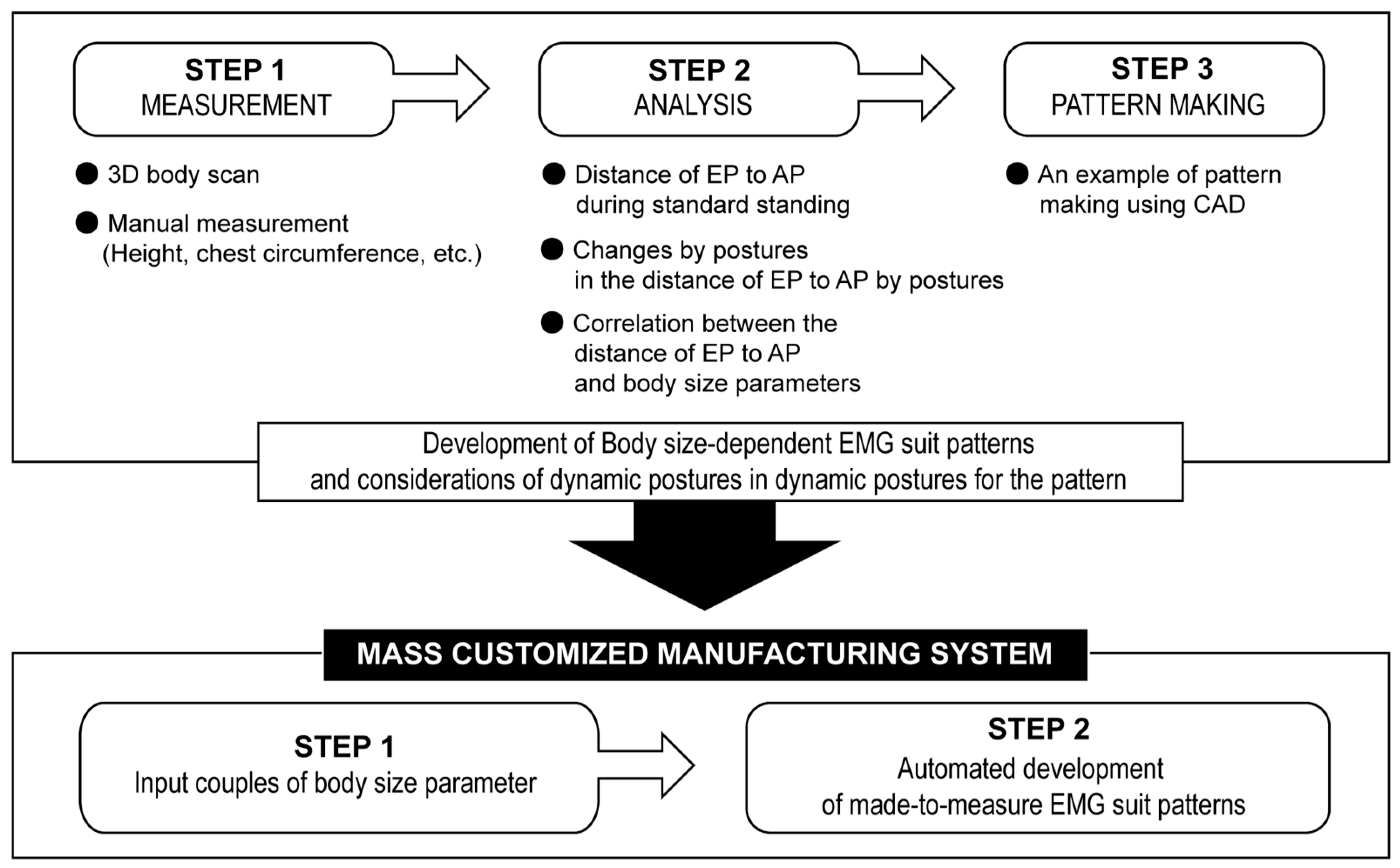
Figure 1. Schematic diagram of the conceptual framework of the current study and its application to the mass-customized manufacturing system.
Sustainability 13 02654 g001
Figure 2. Extracted landmarks, including 28 anthropometric landmarks (AP in black circles) and EMG electrode attachment points (EP in blue circles). The red dotted lines indicate reference lines, which were used to extract distances with nearby EPs.
Sustainability 13 02654 g002
Figure 3. 3D body scan postures: (a) a standard standing posture; (b) a dynamic standing posture with vertically raised arms; (c) a dynamic standing posture with arms stretched and elbows flexed to 90°; and (d) a dynamic standing posture with 90° of knee flexion of the right leg.
Sustainability 13 02654 g003
Figure 4. Preliminary process for specifying EMG electrode location: (a) a subject’s scan data; (b) designing basic patterns of bodies, sleeves, and pants and its virtual fitting on scan data using CLO 3D; and (c) manual positioning EMG electrodes on the scan data on clothing patterns by adjusting transparency of the fabric.
Sustainability 13 02654 g004
Figure 5. Differences in the distance in the EMG electrode attachment points (EP) to anthropometric points (AP) in three different postures in the upper body (N = 5): UT, upper trapezius; MD, middle deltoid; PM, pectoralis major; LD, latissimus dorsi. * p < 0.05, ** p < 0.01 analyzed by the Wilcoxon test.
Sustainability 13 02654 g005
Figure 6. Scatter plots explain that the electrode location of upper trapezius (UT) may be size-dependently determined based on the distance from lateral shoulder (b), rather than the distance from the back neck point (a). The ratio of distances to adjacent anthropometric landmarks (back neck and lateral shoulder) also shows a significant correlation with shoulder length (c).
Sustainability 13 02654 g006
Figure 7. Example of customized patterns for smart EMG suits with EMG electrode attachment location on the tight-fitting garment patterns: (a) bodice pattern and the location of EPs of the upper trapezius (UT), pectoralis major (PM), and latissimus dorsi (LD), (b) sleeve pattern and the location of EPs of the middle deltoid (MD) and biceps brachii (BB); and (c) pants pattern and the location of EPs of the gluteus maximus (GM), rectus femoris (RF), adductor magnus (AM), and biceps femoris (BF). Blue dotted lines indicate the line segments for which body size-dependent equations between the anthropometric landmarks (blue closed circles) and EMG electrode locations (black opened circles) can be derived.
Sustainability 13 02654 g007
Table 1. Description for the EMG electrode attachment locations.
Body RegionMuscleAnthropometric Landmarks and Lines a Body Size Parameter
Upper body (trunk) UTback neck, side neck, lateral shoulderheight, chest circ., back length, shoulder length
PMfront neck, side neck, lateral shoulder, front waist, front waist (omphalion), anterior mid-sagittal line
LDback neck, axillary level at midspine, side waist, back waist, side waist (omphalion), back waist (omphalion), posterior mid-sagittal line
Upper body (sleeve)MDlateral shoulderheight, arm length, chest circ.
BBlateral shoulder, elbow circ. line
Lower bodyGMside waist, back waist, lateral waist (omphalion), back waist (omphalion), crotch, waist circ. lineheight, waist circ., hip circ., thigh circ.
RFcrotch, knee circ. line, coronal plane
AMcrotch, knee circ. line
BFcrotch, knee circ. line, mid-coronal line
a Anthropometric landmarks and lines to which distances from each muscle measurement points were extracted; UT, upper trapezius; PM, pectoralis major; LD, latissimus dorsi; MD, middle deltoid; BB, bicep brachii; GM, Gluteus maximus; RF, Rectus femoris; AM, Adductor magnus; BF, biceps femoris; circ., circumference.
Table 2. Spearman correlation coefficients between body size parameters and distances of EP to AP.
RegionMuscleDistance of EP to APBody Size ParameterSpearman’s Rhop-Value
Upper body (Trunk) UTUT to side neck Height−0.8210.089
UT to shoulderShoulder length0.9000.037
PMPM to front waist (omphalion)Height0.9750.005
PM to front waistChest circumference−0.9000.037
LDLD to back neck Back length−0.9000.037
Lower bodyGMGM to back waistHeight0.9750.005
GM to waist lineHeight0.8210.089
GM to back waist (omphalion)Height0.8210.089
GM to mid-sagittal lineHeight0.8210.089
RFRF to knee lineHeight0.9750.005
AMAM to knee Height−0.8210.089
BFBF to mid-coronal line Height−0.8210.089
BF to kneeWaist circumference−0.9000.037
EP, EMG electrode attachment point; AP, Anthropometric landmarks; UT, upper trapezius; PM, pectoralis major; LD, latissimus dorsi; GM, Gluteus maximus; RF, Rectus femoris; AM, Adductor magnus; BF, biceps femoris.
Publisher’s Note: MDPI stays neutral with regard to jurisdictional claims in published maps and institutional affiliations.