Article

Implementation of a Stable Solar-Powered Microgrid Testbed for Remote Applications

by
Hossein Saberi
1,
Hamidreza Nazaripouya
2,* and
Shahab Mehraeen
1
1
Department of Electrical and Computer Engineering, Louisiana State University, Baton Rouge, LA 70803, USA
2
School of Electrical and Computer Engineering, Oklahoma State University, Stillwater, OK 74078, USA
*
Author to whom correspondence should be addressed.
Sustainability 2021, 13(5), 2707; https://doi.org/10.3390/su13052707
Submission received: 25 December 2020 / Revised: 30 January 2021 / Accepted: 2 February 2021 / Published: 3 March 2021
(This article belongs to the Special Issue Innovative Solutions for Integration of Distributed Energy Resources)

Abstract

:
An intrinsically stable microgrid, operated by inverter-interfaced distributed energy resources (I-DERs) is introduced in this paper. The microgrid is built upon a systematic design method, which is adapted from the operation of the synchronous machine (SM). The proposed method analogizes the dynamics of the dc-link in I-DERs to the rotor dynamics in synchronous generators (SGs) and utilizes the capacitor as energy storage. Thus, the proposed mechanism relaxes battery usage for frequency control, and by using the capacitive stored energy, provides a high fault ride-through capability, which is suitable for both on-grid and off-grid applications. Based on stability analysis of the SG and the dynamic state matrix eigenvalues for multimachine power system, the dc-link capacitor of I-DERs is characterized in the context of microgrid. The dc-link capacitor stores kinetic energy similar to the rotor of the SG and provides inertia in transients without the need of battery storage. The inverter angle responds to the change of the dc link voltage (energy). The dc-link voltage is then controlled similar to the field control pertaining to the SG. Finally, a governor-like mechanism is applied to maintain dc-link voltage stability. Simulation and experimental results are provided to show the effectiveness of the proposed design mechanisms.

1. Introduction

Widespread integration of inverter-interfaced distributed energy resources (I-DERs) raises two major concerns about operation of the power grids; namely, the small fault ride-through capability and the decrease in the level of power system inertia due to the renewable sources. Currently, I-DERs do not play a major role in the frequency stability of the grid. Instead, regardless of the amount of available energy in the primary source of I-DERs, they are curtailed in contingencies due to their small fault ride-through capabilities. As the grid is evolving by the proliferation of I-DERs, the benefits of I-DERs’ participation in frequency control have been recognized and several frequency regulation strategies for I-DER inverters have been suggested [1]. These control methods are substitutes to the conventional control strategies that extract the maximum active power from I-DERs and treat them as constant-power sources with no frequency response capabilities. Additionally, an added high fault ride-through feature is desirable, which makes the fault detection easier and thus help with the system reliability.
The existing frequency control methods can be categorized into two main groups. The first group includes methods that adjust the active power reference of power converters based on the feedback from the grid frequency. The employed phase-lock loop (PLL) must be precisely designed to avoid instability to the power converter, especially when the converter is integrated with weak grids characterized by low short circuit ratios [2,3]. However, in these methods, the power is mostly extracted from a battery storage and the additional cycles could cause faster battery degradation.
The second group includes the virtual synchronous machines that mimic frequency regulation characteristics of synchronous generators (SGs) such that the power converter provides inertial responses to the grid frequency changes [4,5,6]. The advantage of these methods is that the available synchronous generator control mechanisms can be implemented. In this group, several methods have been proposed, such as synchronverters [7], virtual synchronous machine (VSM) [8,9], virtual inertia control [10], virtual synchronous generators (VSGs) [11], and global dc-link voltage-based droop control [12]. However, the majority of the state-of-the-art in this group still relies on a constant dc-link voltage that requires a battery storage. In addition, most of the literature available on the power swing-based virtual synchronization [13,14,15], focuses on control of I-DERs to provide additional frequency support in power systems, especially with weak ac grids. Thus, this methodology has not been adequately explored for self-stabilizing the islanded microgrid that are solely powered by renewable energy sources such as solar.
In an islanded microgrid supplied by renewables, the power converters known as grid forming inverters play a significant role in providing the frequency reference and stability of the system. If no rotational machines exist in the microgrid, stability is restricted to the dc-link voltage and phase angle stability. However, the frequency stability of renewable-based microgrids is challenging due to the lack of inertia in the grid. The conventional solution to this problem is to deploy a battery to emulate inertia [16,17]. However, battery energy storage systems are costly, and extensive charge–discharge cycles used in frequency control reduces their lifetime. In addition, this method requires high-power batteries that are more expensive than high-energy ones. Alternatively, one can utilize the energy stored in the dc-link capacitors of the power converters as virtual inertia. That is, the dynamics of the dc-link capacitor mimics the dynamics of the machine’s rotor to provide a similar inertial response. With the current developments in supercapacitor and film capacitor technologies, high capacitance is available for storage applications. As a result, the dc-link capacitor can be characterized appropriately to realize the intrinsic stability in a standalone microgrid. Unlike virtual synchronization methodology, which uses the virtual angular speed as the basis for the speed control, this paper proposes a model based on a physical state (i.e., dc-link voltage). Subsequently, the non-trivial stability of the interacting inverters using virtual synchronization control is introduced by utilizing a “governor + SG” operation, via bringing the dc-link voltage measurement into the control mechanism.
The contributions in this paper can be listed as follows:
(1)
Develop a physical parameter-based model for self-stabilizing operation of interactive inverters borrowing from synchronous generator dynamics;
(2)
Introduce a systematic design method for an intrinsically stable microgrid, operated by I-DERs using a “governor + SG” mechanism;
(3)
Interpret inverter inertia via dc-link capacitance and;
(4)
Implement a stable microgrid without using battery storage systems. That is, dc-link voltage stability and frequency stability is achieved with no battery storage utilization, although they can still be used for other purposes such as peak shaving and load shifting.
To this end, the dc-link voltage stability in a solar-based microgrid is explicitly considered and simultaneous output voltage and frequency (phase) control are targeted. The proposed microgrid is composed of photovoltaic (PV) units, which are connected in a small-scale power system where no high inertia equipment exists. The synchronous generator’s intrinsic stability is imitated in the PV units with the dc-link voltage and phase angle-control similar to the SG rotor speed and angle control. PV terminal voltage is then controlled through the amplitude modulation factor to adjust power to that of the synchronous generator and thus terminal voltage control is achieved. A dc–dc converter is used to connect each PV unit to the corresponding inverter. A fast governor measures the dc-link voltage and controls the input power to the dc-link by adjusting the dc–dc converter’s duty cycle. Thus, the dc-link voltage is stabilized through grid power control (inverter) on one side and the source (renewable) power control (governor/dc–dc converter) on the other side, like speed in synchronous generators, with the exception that the two controls’ time constants may or may not be far apart.
This work is established on the prior research on inverter modeling [18,19]. It utilizes a field + governor-like mechanism for low-inertia power systems with no rotating mass. It is important to note that this methodology is different from the conventional synchronverter, as in this method the dc-link is not constant and is used as a physical dynamic storage similar to the machine’s rotor inertia.
The rest of the paper is organized as follows: in Section 2, the principles of the proposed modeling, control, and design strategy are presented. Then, Section 3 provides simulation and experimental test results. Finally, the concluding remarks are given in Section 4.

2. System Topology and Proposed Control Scheme

2.1. System Topology

The block diagram of a solar-based microgrid is depicted in Figure 1. In this system, the buck converter can be used as the dc–dc converter to connect each PV unit to the corresponding inverter. Although the boost converter possesses higher output voltage with no (high-frequency) transformer, due to the stability advantages, the buck converter is suggested in PV systems [20,21]. For increasing the voltage level, the forward converter [22] or ac transformers can be used. Due to the similarity in the functions (except the transformer turns ratio) and for simplicity, a buck converter is modeled here. In this structure, there are two capacitors at the input and output of the dc–dc converter. The input capacitor provides a smoother voltage at the input, and the output (dc-link) capacitor plays a vital role in the system stability by buffering the varying grid power.
In order to realize a stable operation for a system with PV units as the primary sources of energy, voltage of the PV unit should vary between the open circuit voltage (Voc) and the maximum power point voltage (Vmpp). The dc–dc converter duty ratio varies in response to the dc-link voltage, to allow for sufficient PV power and keep the dc-link voltage in the permissible range like the governor controlling speed. The dc–ac conversion is performed by a three-phase two-level PWM inverter. The inverter is connected to the point of common coupling through an LC filter and (if needed) a step-up transformer.
Remark 1.
This study focused on transient stability, and thus, long-term control targets such as maximum power-point tracking (MPPT) were not the objective. Rather, the proposed modeling and control scheme aimed at providing stability for low-inertia small-scale power systems at the level of primary control. The proposed approach studied disturbances that cause rapid voltage fluctuations and adversely affect the PV power generation and potentially lead to the entire network instability. Due to small available reserve power in the network, it is necessary that the PV units operate at a voltage higher than that of the MPP; so that some reserve power becomes available for transients and steady-state operations when needed (similar to the spinning reserve).

2.2. System Model and Control Scheme

The dc–dc converter is connected to the inverter through the dc-link capacitor. The energy stored in this capacitor acts like the kinetic energy stored in rotating mass of the synchronous generator. The amount of stored energy at the dc link depends on the size of the capacitor and the dc-link voltage [18]. Therefore, one has
C V C V ˙ C = P i n P o
where P i n is the power injected to the capacitor from the dc–dc converter and comes from the primary source of energy (e.g., PV unit), P o is the delivered power to the inverter, and V C is the dc-link capacitor voltage.
On the other hand, the delivered power to the grid by inverter can be written as (2):
P ¯ e = B V i n v V sin ( γ θ )
where B is the admittance that connects the inverter to the grid (including the filter), V i n v and γ are the voltage magnitude and phase angle of the fundamental harmonic at the inverter’s output terminal, and V and θ are the grid bus voltage magnitude and phase angle, respectively. Neglecting the inverter’s losses results in P ¯ e = P o . In (2), B is constant, V and θ are also not under control and dictated by the grid, and V i n v should be within the allowable range (normally between 0.95 and 1.05 pu).
Remark 2.
The conventional dq decomposition schemes aim at decoupling active and reactive power controls and apply the control through inverter magnitude modulation factor and phase angle controls. By contrast, in this work, the magnitude modulation factor and phase angle controls are directly deployed to manage transient stability of the dc-link voltage, to which active power swing is tightly coupled. Thus, angle γ and inverter voltage modulation factor are adjusted here to control the inverter’s output power.
A new variable λ is introduced to control γ in the inverter as shown in (3) [18]:
γ ˙ = λ .
Parameter λ resembles rotor speed (ω) in the synchronous generator. The rotor speed defines the kinetic energy stored in the rotor as (4):
ω ˙ = 1 / M ( P m P e l e c )
where M is the angular momentum, P m is the input mechanical power, and P e l e c is the output electrical power. In order to relate the new variable λ to the stored energy in the dc link capacitor, it can be defined as (5):
λ ˙ = 1 / C ( P i n P o )
By using Equation (1):
λ ˙ = V C V ˙ C
that yields:
λ = ( V C 2 V C 0 2 ) / 2
Hence, λ is the scaled changes in capacitor stored energy.
Remark 3.
By using traditional per unit conversion in swing studies, one can start form C V ˙ C = i L i o and yield C S b V C V ˙ C = ( i L i o ) V C S b , and consequently in the more familiar form V c V ˙ C = S b C ( P in pu P o pu )   comparable with the SG counterpart: ω m ω ˙ m = S b J ( P m pu P elec pu ) = ω s 2 2 H ( P m pu P elec pu ) . Similar to SG, where the inertia constant is defined as   H = 1 / 2 j ω m 2 S b , here the inertia constant can be defined as H ¯ = 1 / 2 CV cb 2 S b that represents the duration in seconds that the capacitor can deliver the base power at the base voltage, where V cb is the dc base voltage and S b is the base power. Here, one can follow two strategies to imitate a synchronous behavior; that is, either creating similar inertia H in the renewable and in the target synchronous generator or mimicking similar eigenvalues in the renewable to those of the rotating machine. The former leads to H ¯ = H and thus C = J ω s 2 V cb 2 , while the latter leads to ω s 2 2 H = V cb 2 2   H ¯ and C = 2 HS b ω s 2 . In this paper, to ensure the same damping characteristic the second option was selected.
In the synchronous generators, (4) relates the input and output powers to the rotor speed. The difference between input and output powers results in kinetic energy stored in the generator rotating mass and is a function of rotor speed and inertia coefficient. In the I-DER system, (5) relates the ac output power, the input dc power, and the dc-link stored energy. The difference between input and output powers results in stored energy at the dc-link capacitor that is a function of dc-link voltage and capacitor size.
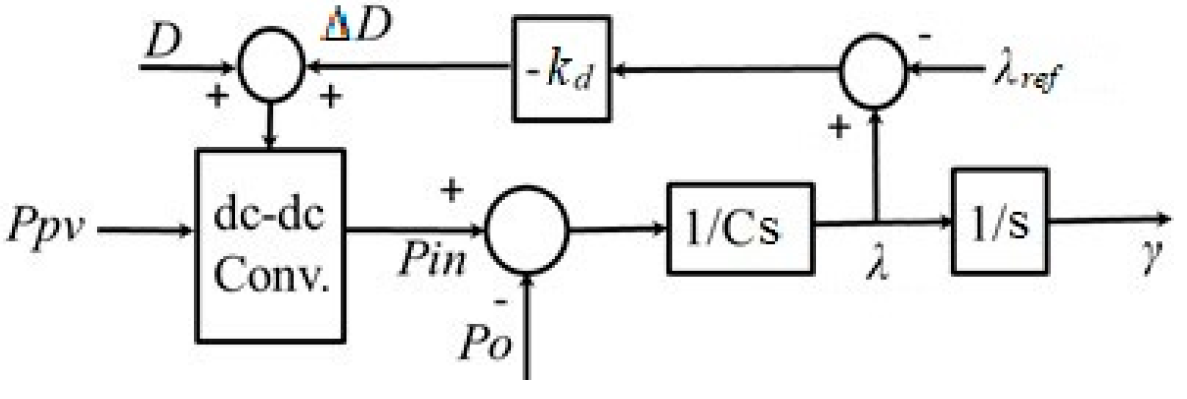
In the synchronous generators, the governor mechanism provides additional torque during disturbances in the power system. Any deviation from the synchronous speed causes an additional steam/gas torque that opposes the change in the speed of the generator helping maintain the rotor speed. This mechanism can be utilized to maintain the dc-link capacitor voltage in the DER. Thus, as an active power control strategy, any deviation from the steady state value of λ will result in some change in the dc–dc converter’s duty cycle D. This adjustment subsequently changes the operating point of the PV unit, which alters its output power. Thus, any variation in λ is followed by a change in the solar power that helps maintain λ at its steady-state value similar to the operation of the SG’s governor.
Next, inspired by synchronous generator operation an excitation-like mechanism is employed through the inverter amplitude modulation factor to add further transient active power control. Similar to the rotor flux and field voltage in a synchronous generator, two new variables,   E q and E f d , are defined for the I-DER system. Thus, filter mechanism (8) introduced a new dynamic as:
E ˙ q = 1 T d 0 [ ( x d x q ) E q + ( x d x d x q ) V cos ( γ θ ) + E f d ]
where x d and x d are fictitious direct-axis synchronous and transient reactances, respectively, and T d 0 is the direct-axis transient open-circuit time constant that can be selected for the proposed model. Here, these parameters can be set as desired in contrast with the synchronous machines, where the parameters are given for each machine. Considering (8) along with (3) and (5), the model resembles the flux-decay model of the synchronous generator. The benefit of this model is that it makes possible application of all available technologies for a synchronous generator control such as the automatic voltage regulator (AVR), power system stabilizer (PSS), etc.
The output power of the synchronous generator described by the flux-decay model is [23]
P e = ( 1 x d ) V [ E q sin ( γ θ ) ( x q x d 2 x q ) V sin ( 2 ( γ θ ) ) ]
while, the inverter output power is described in (2). In order to have an identical behavior to the flux-decay model, inverter’s output power should be equal to P e in (9). By equating (9) and (2), V i n v , the voltage magnitude at the inverter’s output terminals, is derived as:
V i n v = E q sin ( γ θ ) x q x d 2 x q V sin ( 2 ( γ θ ) ) x d B sin ( γ θ )
In order to attain this voltage, the inverter modulation factor, k i n v , is adjusted such that the fundamental harmonic of the voltage at the inverter output terminal is V i n v ( V i n v = k i n v . V C ) dictated by (10). This adds another degree of freedom in the inverter output power (2) besides angle γ .
In the synchronous machine, controlling E f d helps maintain terminal voltage V and reactive power of the machine using an AVR mechanism. Similarly, in the proposed mechanism, E f d can be used to control inverter voltage V i n v and reactive power of the I-DER system, according to (8)–(10). Nevertheless, constant E f d is utilized in this work for simplicity, as will be explained; other control mechanisms can be added to this mechanism as mentioned earlier.
According to (3), (5), and (8), the I-DER unit is described by a third-order dynamic system where E q , λ, and γ are the state variables while input power P i n and field voltage E f d are the control inputs to the system. Figure 2 shows the operation of the governor. Here, a proportional controller is used; but higher-order controllers can be utilized, too. By assuming dc–dc (buck) converter first-order response, the PV voltage tracks the dc-link voltage according to (11):
k 1 d ( V p v ) d t + V p v = V C D
with 1 k 1 an appropriate time constant. Next, by using D = D o + D , V p v = V p v o + V p v , V C = V C o + V C , D = k d Δ λ , and D o V p v o = V C o and ignoring small terms, (11) can be rewritten as (12):
V C + k d Δ λ V p v o D o Δ V p v =   k 1 D o d ( V p v ) d t
For simplicity, the PV power curve can be considered linear in the falling region and thus Δ P p v = k 2 Δ V p v with Δ P p v = P p v P p v o where P p v o corresponds to V p v o . This in turn changes (12) into (13) as:
1 k 1 ( P p v o P p v k d k 2 V p v o D o Δ λ k 2 D o Δ V C ) P ˙ p v .
By selecting a large gain k d for proportional controller D = k d Δ λ , the last term on the left-hand side can be ignored.
Equation (13) is similar to the conventional SG governor dynamic P ˙ m = 1 T g ( P r e f P m 1 R ω ) . Stability analysis of the proposed control method is very similar to that of the well-established synchronous generators where various standards and methods are available for pertinent settings including IEEE [24,25], which is not included here due to space constraints.

2.3. Parameter Design

Based on the methodology described in Section 2.2., the key step in developing an intrinsically stable solar-powered microgrid is to appropriately characterize the DER’s dc-link capacitor. In this section, the dc-link capacitor will be designed in the context of the solar-powered microgrid using the proposed system model and control scheme. Here, first the counterpart microgrid powered by synchronous generators is considered. Then, based on the stability analysis of the synchronous generators and the dynamic state matrix eigenvalues for the multimachine power system, the proper inertia constant (H) for each machine is obtained, which guarantees the system stability. Finally, H is translated into the size of the dc-link capacitors in the counterpart solar-powered microgrid such that the dc-link capacitor provides the required inertia in the microgrid.
An SG-powered microgrid can be modeled by differential-algebraic equations (DAEs). The differential equations in the PV powered system are described by (3), (6), and (8) along with the dynamic of the proposed governor. Algebraic Equation (14) represent nodal power balance at distributed generation (DG) locations as:
P i = | V | E q x d sin ( γ V ) | V | 2 2 ( 1 x d 1 x q ) sin ( 2 γ 2 V )   =   k = 1 N | V i | | V k | | Y i k |   cos ( θ i θ k + φ i k ) Q i = | V | E q x d cos ( δ V ) | V | 2 ( sin 2 ( γ V ) x q + cos 2 ( γ V ) x q ) = k = 1 N | V i | | V k | | Y i k |   sin ( θ i θ k + φ i k )
and non-DG nodal power balance Equation (15) as:
0 = k = 1 N | V i | | V k | | Y i k |   cos ( θ i θ k + φ i k ) 0 = k = 1 N | V i | | V k | | Y i k |   sin ( θ i θ k + φ i k )
where | Y i k | and φ i k are the magnitude and angle of element ik in the admittance matrix of the network, respectively. The parameters are designed through stability analysis of the linearized microgrid model. Therefore, the DAEs are linearized around the equilibrium point and converted to a set of linearized ordinary differential equations using the reduction methods in [23], shown by (16):
x ˙ = A k x + B k u        
The stability is obtained by proper selection of H for each generator such that all system (16) eigenvalues lie on the left-hand side of the s-plane. Finally, the capacitor sizes are calculated from H using the formulation given in Remark 3.

3. Results

Effectiveness of the proposed scheme is investigated through both simulation and experimental tests. The simulation and experimental setups are designed based on the methodology described in Section 2.3. and includes a target SG-based microgrid and a DER-based counterpart. The state-space equations are developed for single- and two-machine test configurations, and eigenvalues are calculated, which depend on the inertia and control parameters in the system. Each synchronous machine adds four states onto the system including three states representing inverter flux-decay model and one state representing the dynamic of the governor with primary frequency control (see Figure 2).
Next, synchronous generators parameters (adopted form a 690 kV SG) listed in Table 1 are used to form the DER-based microgrid benchmark [26] shown in Figure 3 with I-DERs only. The governor feedback controller (Figure 2) should be designed such that the system retains the initial dc-link voltage. By using (16), the eigenvalues of the SG-powered system are calculated and summarized in Table 2, which are then used for the PV-based microgrid. For the PV-powered microgrid, base power of 2 kVA and dc base voltage of 80 V were selected for per unit calculations. The dc-link capacitance is calculated accordingly as 1 mF, shown in Table 3.

3.1. Simulation Results

The simulations were carried out for the PV-based grid using Matlab\Simulink. First, stable operation of the proposed method in stand-alone condition was evaluated and compared with the synchronverter [7]. The parameters of the systems including the proposed model and the synchronverter are listed in Table 3. These parameters were obtained from the counterpart systems (SG 1 and 2) but at low voltage using per unit values. The target inertia from Table 1 was used along with the DG base power shown in Table 3 and synchronous speed of ω s = 120 π to obtain the dc-link capacitor. This value ensures eigenvalues of Table 2.
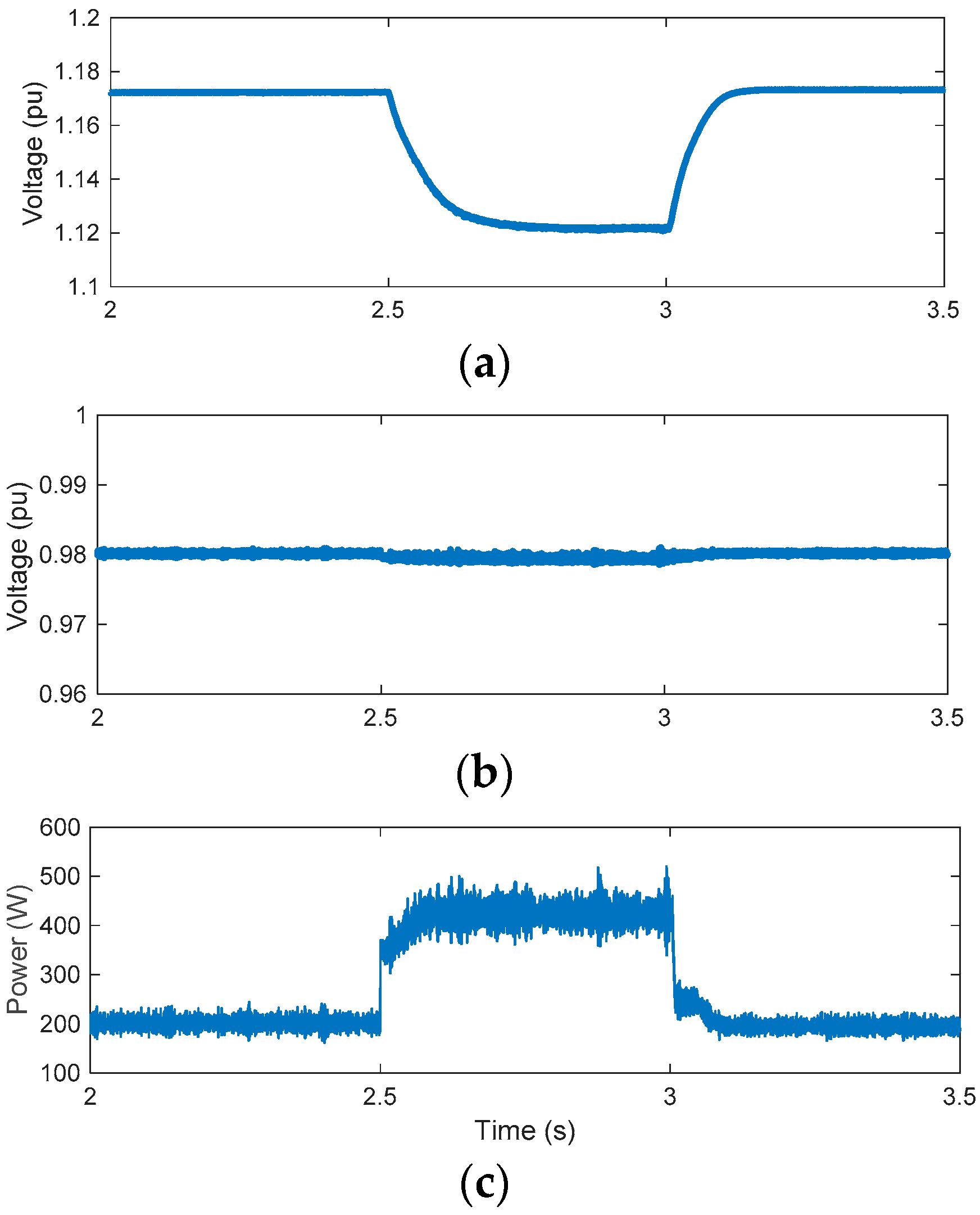
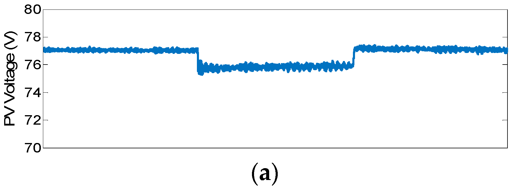
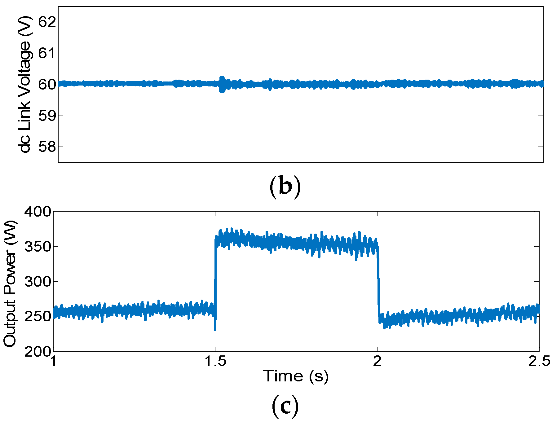
Case 1—Load change (stand-alone I-DER): In the first simulation scenario, the proposed scheme was applied to a stand-alone solar-fed DER that is feeding a local load. At t = 2.5 s the load was stepped up from 200 to 400 W for 0.5s and then returned to its initial value. Satisfactory performance of the proposed control method is shown in Figure 4. The voltage at the PV terminals decreased to provide more power. Subsequently, the governor-like mechanism shown in Figure 2 increased the dc–dc converter duty cycle to maintain the dc-link voltage. The field voltage (Efd) was set to the nominal value to achieve nominal voltage at the inverter output terminals.
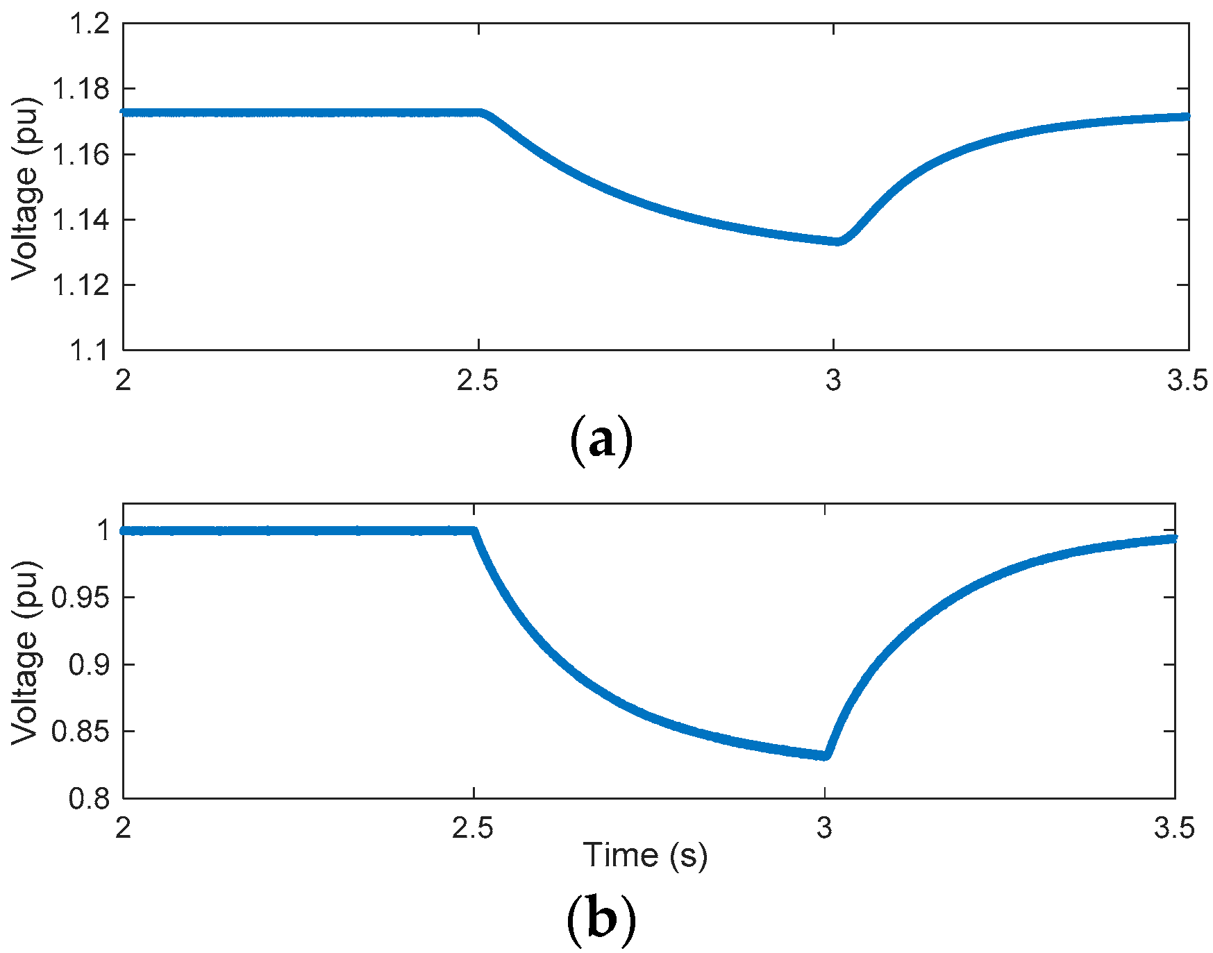
The identical governor mechanism with the same parameters is applied to the dc–dc converter while the governor controller receives feedback from virtual angular speed rather than the proposed state λ (capacitor voltage) associated with the dc-link. As demonstrated in Figure 5, virtual angular speed cannot restore dc-link voltage appropriately, and thus the inverter will shut down due to low dc-link voltage if it is not supplied by battery storage.
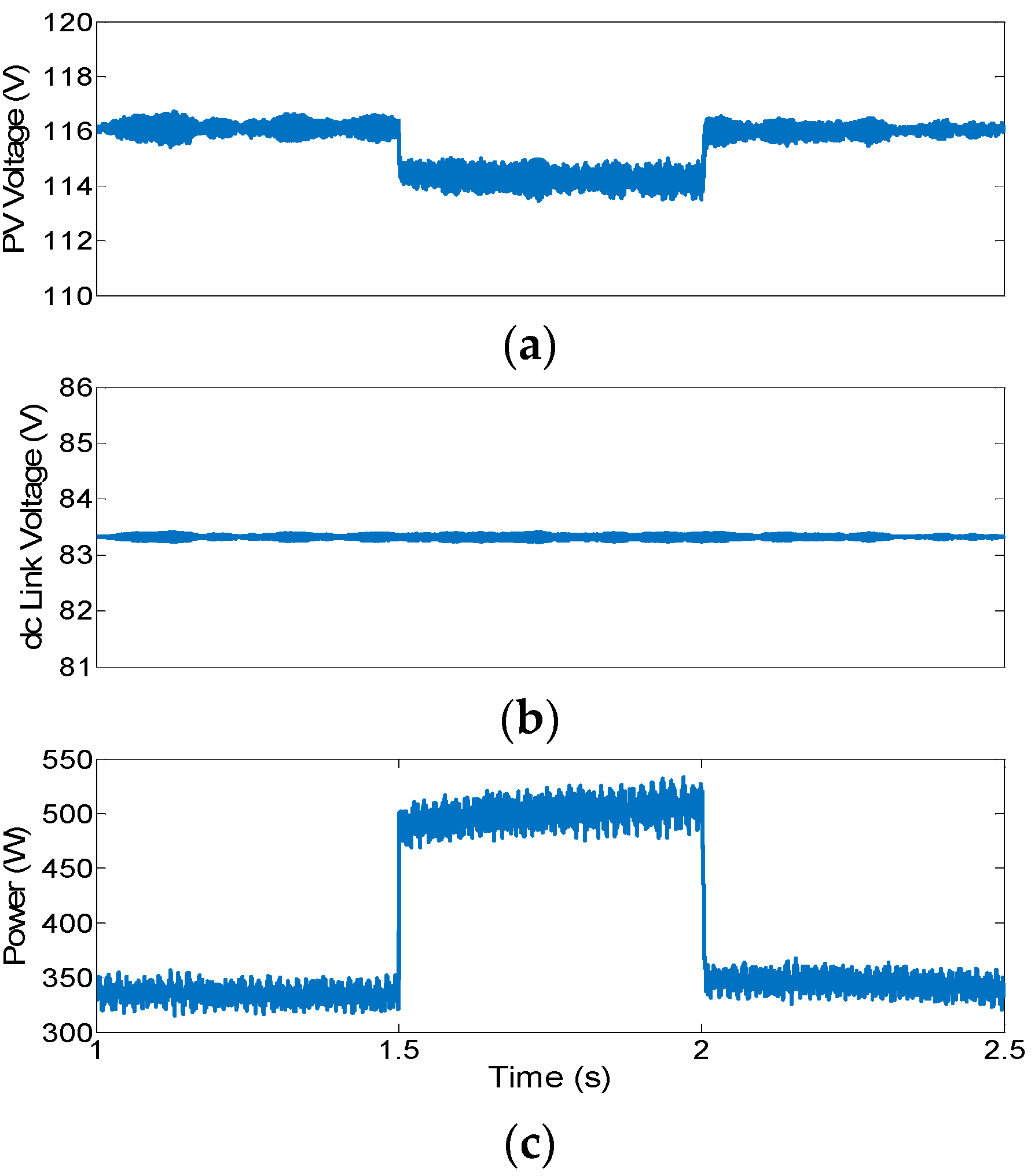
Case 2—Load change (microgrid): In the second simulation scenario, effectiveness of the control scheme was evaluated in the benchmark low-voltage microgrid of Figure 3. Two PV-based DER equipped with the proposed control mechanisms fed five resistive loads in the grid. DER 1 was composed of three PV panels in series and DER 2 included two panels in series. Three-phase transformers were used to increase the ac voltage to that of the grid (208V L-L). Load 4 was connected to the grid at t = 1.5 s and removed after half a second while I-DERs were feeding the grid under normal conditions. The control method can share the load between the I-DERs and the system retained its stability after the first swings. The voltage at the PV terminal decreased to extract more power out of the PV units. This was followed by the buck converter’s duty cycle increase to maintain the dc-link voltage at the initial values as shown in Figure 6 and Figure 7. Additionally, the field control mechanism provides additional regulation via the inverter’s modulation factor according to the excitation-like mechanism of (10). The modulation factor (Kinv) varied to adjust the inverter voltage Vinv and created more damping power according to (2) as shown in Figure 8. It is revealed that through moderated variation of Kin satisfactory performance was achieved. Figure 8c (plotted on a different time scale) shows variation of grid voltage when load was removed (see instant 2 s with increased peak voltage.) It should be mentioned that as the additional load tended to reduce dc-link stored energy and voltage, it resulted in a smaller inverter angle according to (3) and limited the output power. In the absence of an inverter voltage increase through modulation factor control, the delivered power to the load did not increase rapidly to support ac voltage. Thus, the additional dynamic (8) improved load support in the proposed scheme.
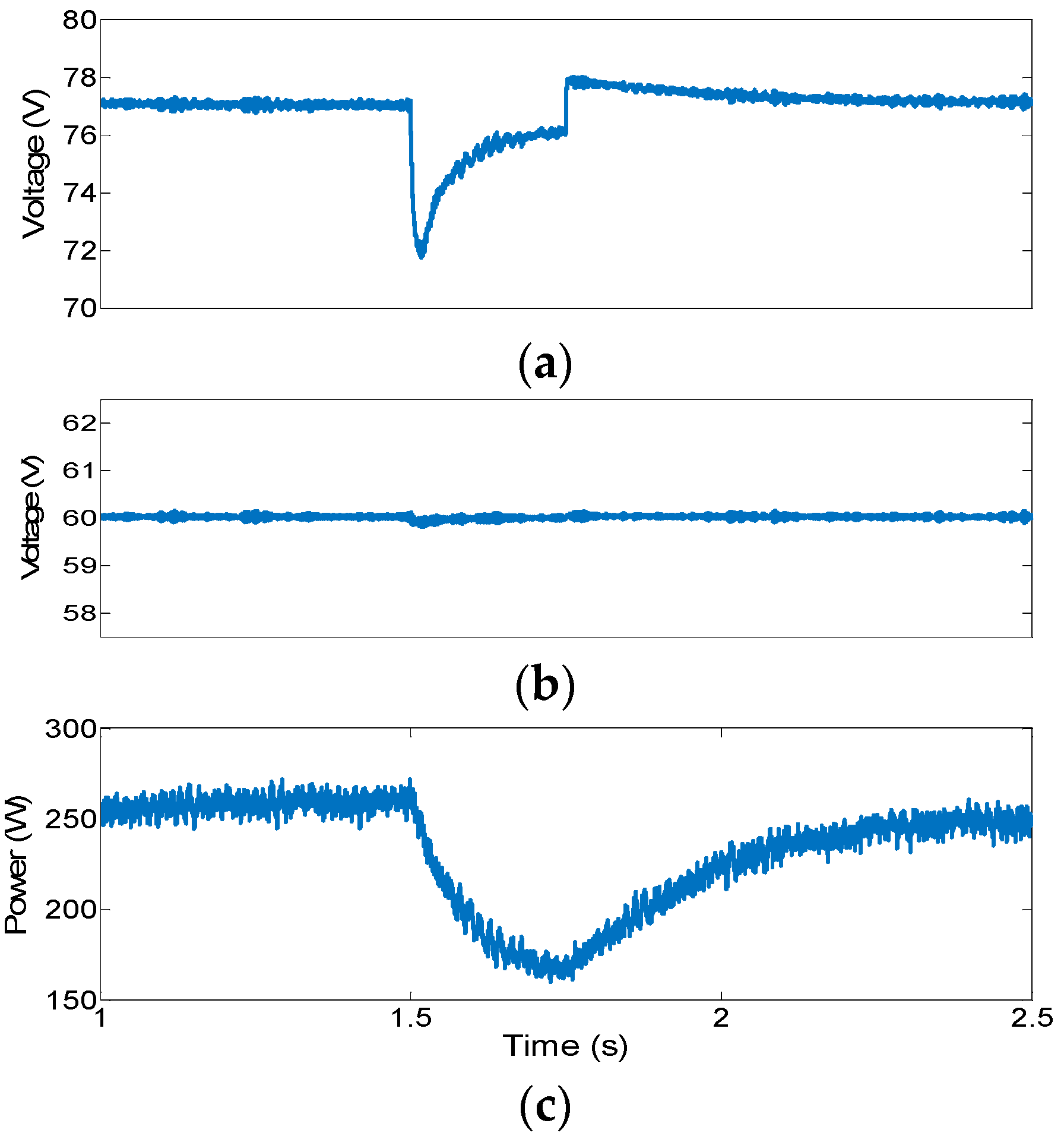
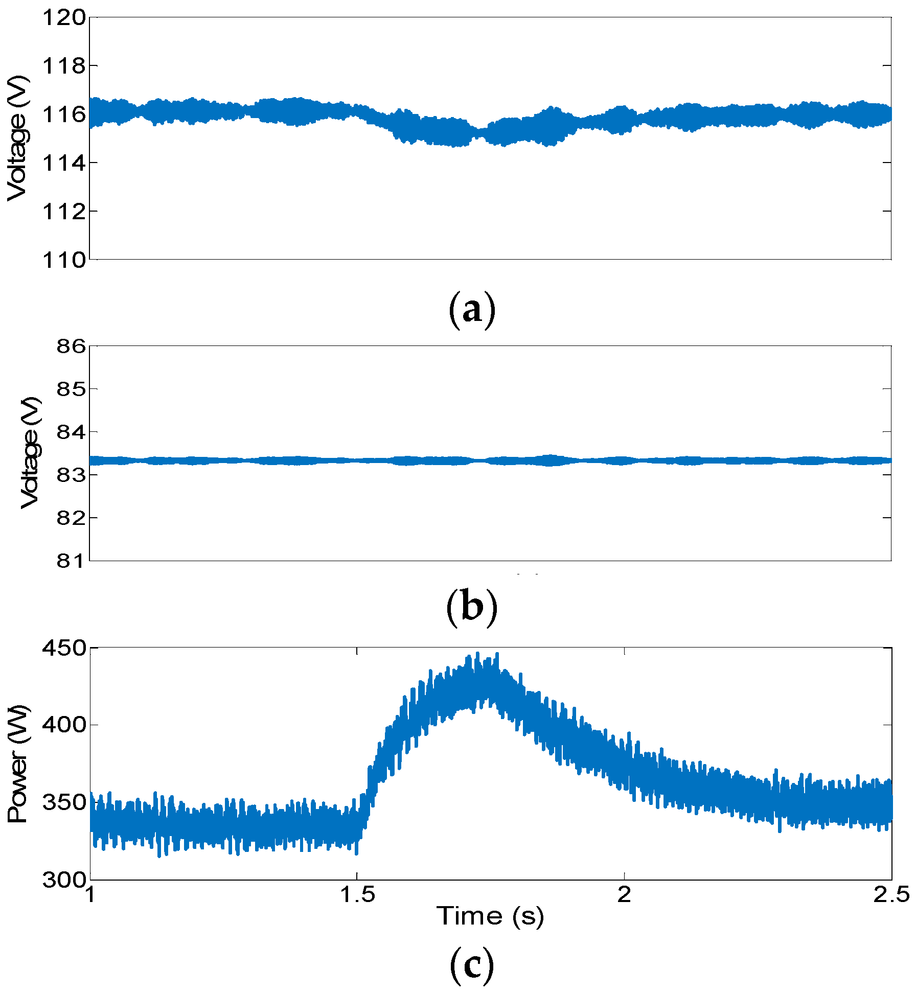
Case 3—Cloud effect: In the third scenario, cloud effect on PV-based DERs was investigated. I-DERs fed the grid in the normal condition while a moving cloud passed over one of the DER’s PV panels and decreased the generation of the I-DER by 50% for half a second. Subsequently, voltage at the PV panels decreased due to the reduced sun irradiance. The voltage is then further reduced to extract more power out of the panels following the dc–dc converter duty cycle increase to maintain the dc-link voltage around the initial set point. The voltage at the other DER’s PV panels dropped, too, to inject more power to the grid and compensate for the lost power as shown in Figure 9 and Figure 10. Note that no additional active power control was utilized and the dc-link voltage regulation mandated active power control similar to the speed control in the synchronous generator for both I-DERs. Additional droop controllers can be added to this scheme if a certain power sharing schedule is desired at longer term actions. However, this task is not necessary in transient stability since the goal is keeping the entire grid at a stable voltage.

3.2. Experimental Results

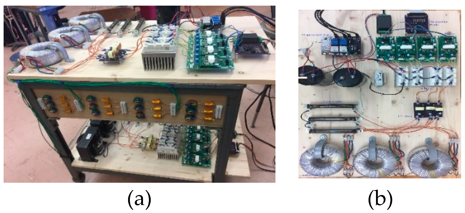
An experimental setup (Figure 11) was built at the Smart grid and Protection lab at Louisiana State University (LSU) to validate stable operation of the system and dynamic voltage control capability of the proposed mechanisms. The solar PV configuration in Figure 1 is applied to the I-DERs of the benchmark microgrid of Figure 3 [26] with parameters listed in Table 3. The dSPACE Microlabbox control platform was used to apply the proposed control scheme using MATLAB/Simulink. The PV panels were connected to the dc-link via dc–dc converters. Subsequently, the inverter generated a three-phase ac voltage at both I-DERs. In order to eliminate the harmonics and create a sinusoidal waveform LC filters were employed at inverter terminals. The resultant voltage fed local loads (Load 1 and Load 2 in Figure 5) and the microgrid through step-up transformers that were arranged in Delta-Y configuration. The Delta-Y configuration helped reduce harmonics and eliminates the need for a common ac–dc ground. Phase-lock loops were employed for synchronism.
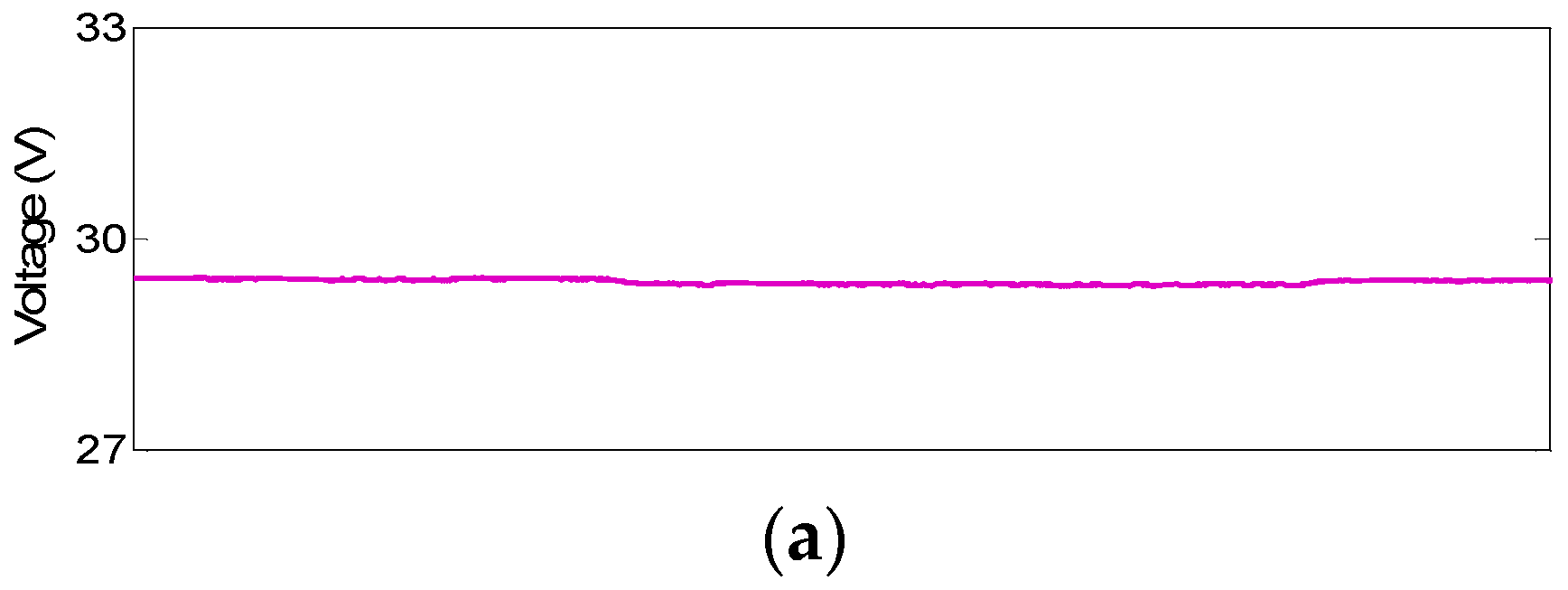
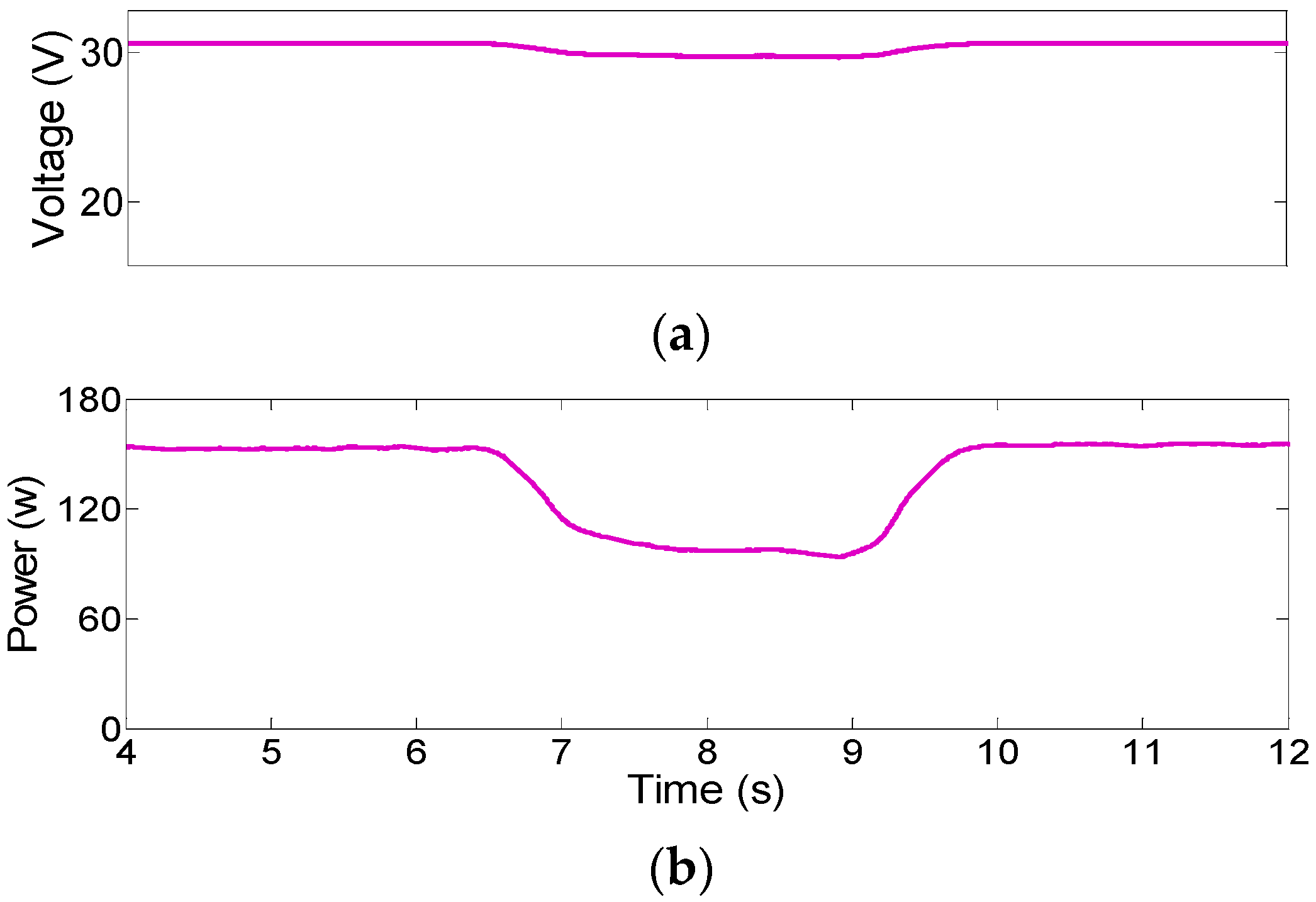
Case 4—Load Change: In the first experiment, the two PV-based DER fed the loads in the low-voltage microgrid. At t = 6.75s, load 4 was added to the grid and removed after four seconds. Dc-link voltage, dc–dc converter’s inductor current, and output voltage and power of each I-DER are shown in Figure 12 and Figure 13. The presented results demonstrate stable performance of the entire system by sharing the added load between the sources while the dc-link voltages remained stable around the initial values. Since there was no droop controller to adjust the share of power, the larger DER (DER 1) automatically put out more power as a result of the dc-link voltage control. The governors of the I-DERs adjusted the dc–dc converters to help maintain the dc-link voltage. Voltage of the microgrid is also shown in Figure 14 that shows satisfactory performance.
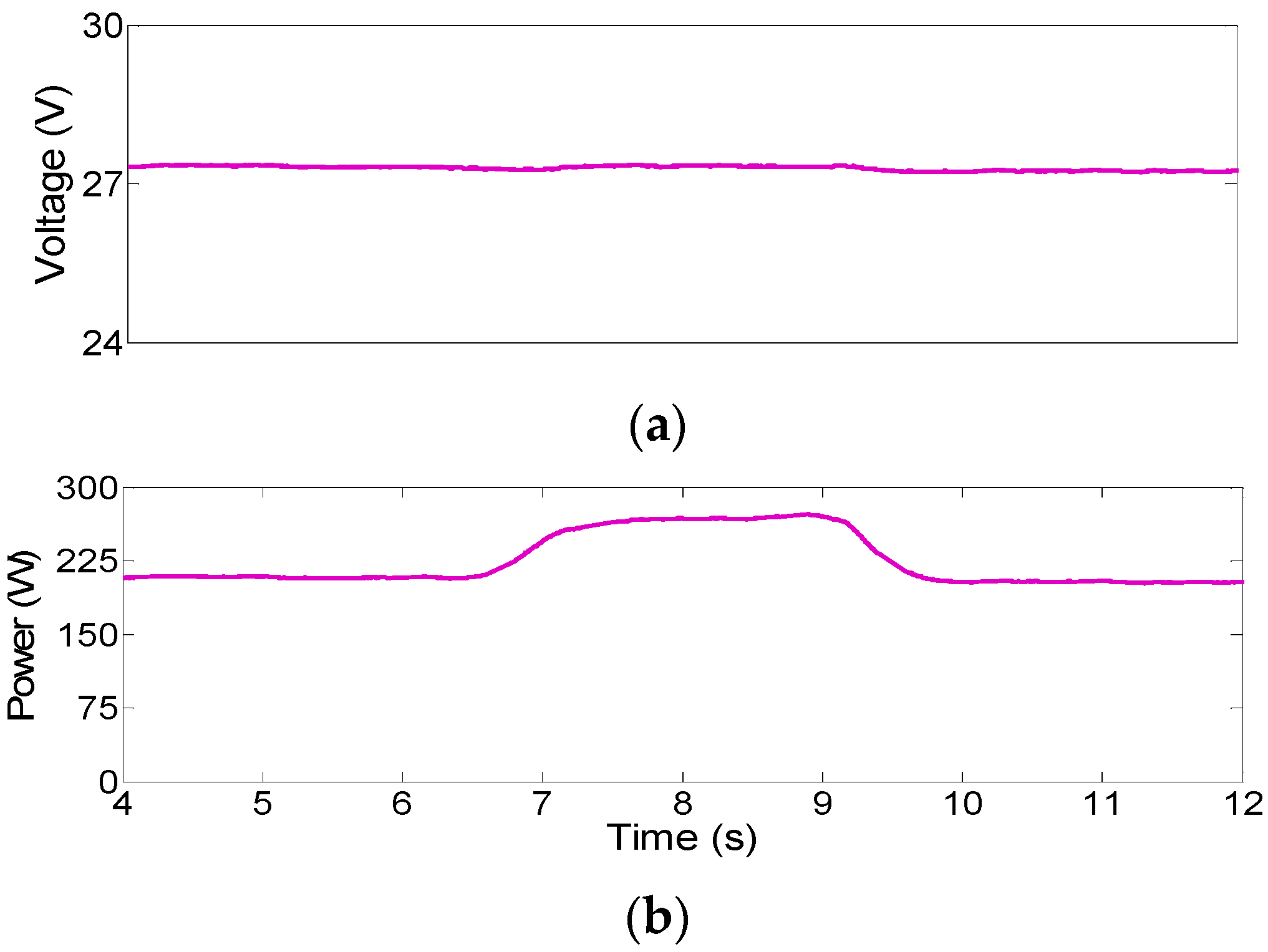
Case 5—Cloud effect: In the second experiment, the effect of a moving cloud on the PV-based DER was investigated. Generation capacity of one of the I-DERs decreased by 30% via a shadow that was imposed on the PV panels of DER#1. Voltage at the shaded PV panels (DER #1) dropped due to a lack of sun irradiance. Subsequently, the controllers attempted to maintain voltage at the dc-link by extracting more power out of the panels leading to a further reduced panel voltage and increased the dc–dc converter duty cycle.
Voltage at the other DER’s PV panels (DER #2) decreased, too, to inject more power to the grid and compensated the lost power. This action was initiated by the tendency of the controller at DER #2 to increase the grid dropped voltage that led to an increased extracted power from DER #2. The dc-link voltage at DER #2 was maintained satisfactorily due to the proposed control mechanisms as shown in Figure 15 and Figure 16.

4. Conclusions

A novel control scheme for attaining voltage stability in low-inertia small-size power systems was proposed and tested through simulation and hardware experiments. The photovoltaic units’ sole storage is the dc-link capacitors that are connected to the grid through voltage source inverters. The entire system is controlled such that the photovoltaic DERs mimic synchronous generators behavior in which the capacitor installed at the inverter dc link, acts similar to the synchronous generator rotating mass and maintains stability of the system in case of a sudden change in the loads or other system disturbances. An excitation-like mechanism is introduced to the inverter while dc–dc converters of solar panels are equipped with governors, which together facilitate I-DER’s voltage control like a synchronous machine speed control. Unlike the majority of virtual synchronization methods, the proposed method is based on a physical state (i.e., dc-link voltage), does not use battery storage systems to provide stability, and offers self-stabilizing operation of inverters rather than just providing frequency support. The proposed control scheme exhibited the desired performance in stand-alone condition and in a microgrid environment. In addition, a prototype system is implemented to validate precise operation of the control approach.

Author Contributions

Conceptualization, S.M. and H.N.; methodology, H.S., H.N. and S.M.; software, H.S.; validation, H.S., H.N.; formal analysis, H.S., H.N. and S.M.; investigation, H.S.; resources, S.M.; data curation, H.S.; writing—original draft preparation, H.S.; writing—review and editing, H.N. and S.M.; supervision, S.M.; project administration, S.M.; funding acquisition, S.M. All authors have read and agreed to the published version of the manuscript.

Funding

Research is supported in part by NSF CAREER ECCS#1151141.

Institutional Review Board Statement

Not applicable” for studies not involving humans or animals.

Informed Consent Statement

Not applicable” for studies not involving humans.

Data Availability Statement

Not applicable.

Conflicts of Interest

The authors declare no conflict of interest. The funders had no role in the design of the study; in the collection, analyses, or interpretation of data; in the writing of the manuscript, or in the decision to publish the results.

Nomenclature

P p v Photovoltaic power
P i n power injected to the dc-link capacitor from the dc-dc converter
P o delivered power to the inverter
P ¯ e delivered power to the grid by inverter
P m input mechanical power
P e l e c output electrical power
V C dc-link capacitor voltage
V c b dc base voltage
V i n v voltage magnitude of the fundamental harmonic at the inverter’s output terminal
V grid bus voltage magnitude
V p v Photovoltaic voltage
γ phase angle of the fundamental harmonic at the inverter’s output terminal
θ grid bus voltage phase angle
| Y i k | magnitude of element ik in the admittance matrix of the network
S b base power
x d direct-axis synchronous reactance
x q quadrature-axis synchronous reactance
x d direct-axis transient reactance
x q Quadrature-axis transient reactance
T d 0 direct-axis transient open-circuit time constant
E q direct-axis field flux linkages
E f d field voltage in a synchronous generator
k i n v inverter modulation factor
B the admittance that connects the inverter to the grid
ωrotor speed in the synchronous generator
M angular momentum
H inertia constant
φ i k angle of element ik in the admittance matrix of the network

References

  1. IEEE Standard for Interconnection and Interoperability of Distributed Energy Resources with Associated Electric Power Systems Interfaces. In IEEE Std 1547-2018 (Revision of IEEE Std 1547-2003); IEEE: Piscataway, NJ, USA, 2018.
  2. Zhang, L.; Harnefors, L.; Nee, H.-P. Power-synchronization control of grid-connected voltage-source converters. IEEE Trans. Power Syst. 2010, 25, 809–820. [Google Scholar] [CrossRef]
  3. Hu, J.; Hu, Q.; Wang, B.; Tang, H.; Chi, Y. Small signal instability of PLL-synchronized type-4 wind turbines connected to high-impedance AC grid during LVRT. IEEE Trans. Energy Convers. 2016, 31, 1676–1687. [Google Scholar] [CrossRef]
  4. Huang, L.; Xin, H.; Wang, Z.; Wu, K.; Wang, H.; Hu, J.; Lu, C. A virtual synchronous control for voltage-source converters utilizing dynamics of DC-link capacitor to realize self-synchronization. IEEE J. Emerg. Sel. Top. Power Electron. 2017, 5, 1565–1577. [Google Scholar] [CrossRef]
  5. Wen, T.; Zhu, D.; Zou, X.; Jiang, B.; Peng, L.; Kang, Y. Power coupling mechanism analysis and improved decoupling control for virtual synchronous generator. IEEE Trans. Power Electron. 2021, 36, 3028–3041. [Google Scholar] [CrossRef]
  6. Li, Y.; Xu, Z.; Wong, K.P. Advanced control strategies of PMSG-based wind turbines for system inertia support. IEEE Trans. Power Syst. 2017, 32, 3027–3037. [Google Scholar] [CrossRef]
  7. Zhong, Q.-C.; Weiss, G. Synchronverters: Inverters that mimic synchronous generators. IEEE Trans. Ind. Electron. 2011, 58, 1259–1267. [Google Scholar] [CrossRef]
  8. Hu, W.; Wu, Z.; Dinavahi, V. Dynamic analysis and model order reduction of virtual synchronous machine based microgrid. IEEE Access 2020, 8, 106585–106600. [Google Scholar] [CrossRef]
  9. Roldán-Pérez, J.; Rodríguez-Cabero, A.; Prodanovic, M. Design and Analysis of Virtual Synchronous Machines in Inductive and Resistive Weak Grids. IEEE Trans. Energy Convers. 2019, 34, 1818–1828. [Google Scholar] [CrossRef]
  10. Sun, D.; Liu, H.; Gao, S.; Wu, L.; Song, P.; Wang, X. Comparison of different virtual inertia control methods for inverter-based generators. J. Mod. Power Syst. Clean Energy 2020, 8, 768–777. [Google Scholar] [CrossRef]
  11. Chen, M.; Zhou, D.; Blaabjerg, F. Modelling, implementation, and assessment of virtual synchronous generator in power systems. J. Mod. Power Syst. Clean Energy 2020, 8, 399–411. [Google Scholar] [CrossRef]
  12. VanDoorn, T.L.; Meersman, B.; De Kooning, J.D.M.; Vandevelde, L. Analogy between conventional grid control and islanded microgrid control based on a global DC-link voltage droop. IEEE Trans. Power Deliv. 2012, 27, 1405–1414. [Google Scholar] [CrossRef] [Green Version]
  13. Peng, Q.; Yang, Y.; Liu, T.; Blaabjerg, F. Coordination of virtual inertia control and frequency damping in PV systems for optimal frequency support. CPSS Trans. Power Electron. Appl. 2020, 5, 305–316. [Google Scholar] [CrossRef]
  14. Zhong, Q.-C.; Nguyen, P.-L.; Ma, Z.; Sheng, W. Self-synchronized synchronverters: Inverters without a dedicated synchronization unit. IEEE Trans. Power Electron. 2014, 29, 617–630. [Google Scholar] [CrossRef]
  15. Kim, J.; Lee, S.H.; Park, J.-W. Inertia-free stand-alone microgrid—Part II: Inertia control for stabilizing DC-link capacitor voltage of PMSG wind turbine system. IEEE Trans. Ind. Appl. 2018, 54, 4060–4068. [Google Scholar] [CrossRef]
  16. Lamichhane, S.; Nazaripouya, H.; Mehraeen, S. Micro Grid Stability Improvements by Employing Storage. In Proceedings of the 2013 IEEE Green Technologies Conference (GreenTech), Denver, CO, USA, 4–5 April 2013. [Google Scholar]
  17. Fang, J.; Tang, Y.; Li, H.; Li, X. A battery/ultracapacitor hybrid energy storage system for implementing the power management of virtual synchronous generators. IEEE Trans. Power Electron. 2018, 33, 2820–2824. [Google Scholar] [CrossRef]
  18. Kazemlou, S.; Mehraeen, S. Novel decentralized control of power systems with penetration of renewable energy sources in small-scale power systems. IEEE Trans. Energy Convers. 2014, 29, 851–861. [Google Scholar] [CrossRef]
  19. Saberi, H.; Mehraeen, S. A simultaneous voltage and frequency control scheme for photovoltaic distributed generation units in small-scale power systems. In Proceedings of the 2017 IEEE Energy Conversion Congress and Exposition (ECCE), Cincinnati, OH, USA, 1–5 October 2017. [Google Scholar]
  20. Pilawa-Podgurski, R.C.N.; Perreault, D.J. Submodule integrated distributed maximum power point tracking for solar photovoltaic applications. IEEE Trans. Power Electron. 2013, 28, 2957–2967. [Google Scholar] [CrossRef] [Green Version]
  21. Walker, G.; Sernia, P. Cascaded DC–DC converter connection of photovoltaic modules. IEEE Trans. Power Electron. 2004, 19, 1130–1139. [Google Scholar] [CrossRef]
  22. Mohan, N.; Undeland, T.M.; Robbins, W.P. Power Electronics: Converters, Applications, and Design; Wiley: Hoboken, NJ, USA, 2002. [Google Scholar]
  23. Sauer, P.W.; Pai, M.A. Power System Dynamics and Stability; Prentice Hall: Upper Saddle River, NJ, USA, 1998; Volume 101. [Google Scholar]
  24. IEEE Recommended Practice for Excitation System Models for Power System Stability Studies. In IEEE Std 421.5-2016 (Revision of IEEE Std 421.5-2005); IEEE: Piscataway, NJ, USA, 2016; pp. 1–207.
  25. IEEE Guide for Identification, Testing, and Evaluation of the Dynamic Performance of Excitation Control Systems. In IEEE Std 421.2-2014 (Revision of IEEE Std 421.2-1990); IEEE: Piscataway, NJ, USA, 2014; pp. 1–63.
  26. Nazaripouya, H.; Mehraeen, S. Modeling and nonlinear optimal control of weak/islanded grids using FACTS device in a game theoretic approach. IEEE Trans. Control. Syst. Technol. 2015, 24, 158–171. [Google Scholar] [CrossRef]
Figure 1. The entire system block diagram.
Sustainability 13 02707 g001
Figure 2. Governor mechanism.
Sustainability 13 02707 g002
Figure 3. Benchmark low-voltage microgrid.
Sustainability 13 02707 g003
Figure 4. Case 1: The proposed model operation in stand-alone operation: (a) voltage at the photovoltaic (PV) terminals, (b) voltage at the dc-link, and (c) output power.
Sustainability 13 02707 g004
Figure 5. Case 1: Synchronverter performance in stand-alone operation: (a) voltage at the PV terminals and (b) voltage at the dc-link.
Sustainability 13 02707 g005
Figure 6. Case 2: Distributed energy resource (DER) #1—performance of the proposed controller during load change: (a) PV output voltage, (b) dc-link voltage, and (c) DER output power.
Sustainability 13 02707 g006
Figure 7. Case 2: DER #2—performance of the proposed controller during load change: (a) PV output voltage, (b) dc-link voltage, and (c) DER output power.
Sustainability 13 02707 g007aSustainability 13 02707 g007b
Figure 8. Case 2: Voltage at DER #1: (a) output voltage Root Mean Square (RMS) value, (b) inverter modulation factor, and (c) grid voltage waveform.
Sustainability 13 02707 g008
Figure 9. Case 3: DER#1—performance of the proposed controller in the cloud scenario: (a) PV output voltage, (b) dc-link voltage, and (c) DER output power.
Sustainability 13 02707 g009
Figure 10. Case 3: DER#2—performance of the proposed controller in the cloud scenario: (a) PV output voltage, (b) dc link voltage, and (c) DER output power.
Sustainability 13 02707 g010
Figure 11. Experimental setup: (a) implemented low-voltage microgrid and (b) detailed graph of a DER inverter unit.
Sustainability 13 02707 g011
Figure 12. Case 4: Hardware test—DER#1 performance during load change: (a) dc link voltage, (b) dc–dc converter inductor current, and (c) DER output power.
Sustainability 13 02707 g012
Figure 13. Case 4: DER#2 performance during load change: (a) voltage at dc link, (b) dc–dc converter inductor current, and (c) DER output power.
Sustainability 13 02707 g013aSustainability 13 02707 g013b
Figure 14. Case 4: Voltage at Bus 1: grid phase voltage.
Sustainability 13 02707 g014
Figure 15. Case 5: DER#1 performance in presence of moving cloud: (a) voltage at dc link and (b) DER output power.
Sustainability 13 02707 g015
Figure 16. Case 5: DER#2 performance in presence of moving cloud: (a) voltage at dc link and (b) DER output power.
Sustainability 13 02707 g016
Table 1. Synchronous generator (SG)-powered microgrid parameters.
ParametersSG 1SG 2
d-axis synchronous reactance ( x d )0.295 pu0.2495 pu
d-axis transient reactance ( x d )0.0697 pu0.0531 pu
d-axis open-circuit time constant ( T do )6.56 s5.7 s
q-axis synchronous reactance ( x q )0.282 pu0.237 pu
inertia constant H (s)0.0302 s0.0358 s
Table 2. System eigenvalues.
Eigenvalues
−7.9299 + 0.0000i−1.0419 − 135.5989i
−4.9906 + 61.2965i−0.3522 + 0.0000i
−4.9906 − 61.2965i−0.1629 + 0.0000i
−1.0419 + 135.5989i−5.5 × 10⁻⁷ + 0.0000i
Table 3. Parameters of the system.
HardwareValuesModelValues
Pannel Voc39.5 V x d 0.295 pu
Pannel Vmpp34 V x d 0.069 pu
Pannel Pmpp280 W x q 0.282 pu
Cin and C1 mFTd06.56 s
L2.5 mHB5 pu
fs10 kHzDp0.2026
Line Inductance (LL)20 mHLine Resistance (RL)0.5 Ω
Vdc-base 80 VdcPbase2 kVA
Publisher’s Note: MDPI stays neutral with regard to jurisdictional claims in published maps and institutional affiliations.