Abstract
Harnessing ocean wave energy is an old challenge that has gained momentum in recent years. In this paper, we present the flow and electrical characterization of a prototype of an alternate liquid metal magnetohydrodynamic (MHD) generator at a laboratory scale which has the potential to make use of the energy of marine waves for its conversion into electrical energy. The eutectic alloy Galinstan, used as a working fluid, was driven in oscillatory motion in a duct of a rectangular cross-section exposed to a transverse magnetic field generated by permanent neodymium magnets. The electric current induced by the motion of the liquid metal in the magnetic field was collected through copper electrodes and delivered to the load. The oscillatory axial velocity component along the duct was measured using ultrasonic Doppler velocimetry for different oscillation frequencies. In turn, the output currents and voltages were measured for different operation conditions and the electric power and efficiency were estimated from experimental measurements. The coupling of this generator to a wave energy converter (WEC) is discussed.
1. Introduction
The huge potential of ocean energy has encouraged the search for appropriate technologies that can take advantage of this resource in the short term. In particular, recent estimates indicate that the global wave energy potential of oceans is 29.5 PWh/yr, wich is higher than the world electricity consumption of 2018 (26 PWh/yr) [1,2]. Since the pioneering contributions of Girard [3] and Masuda [4], different wave energy converters (WEC) have been proposed with the aim of harvesting the energy of waves and transforming it into useful energy, particularly, into electricity. WECs can be classified by their location zone in shoreline, nearshore, and offshore, according to whether they are located on the coast, relatively close to the shoreline (with water depths no greater than 50 m) or in waters with depths greater than 50 m [3,5,6]. WECs can also be distinguished in two wide categories through the power conversion system used, namely direct and indirect conversion systems. Direct conversion systems transform the energy captured by the WECs into useful energy in a single step as, for instance, the linear electric generator [7,8,9,10]. On the other hand, indirect conversion systems transform the energy coming from the WECs in two or more steps, for example, a system of air turbine coupled with a rotary electric generator that transforms the energy captured by an oscillating water column into electricity [11,12,13,14,15].
Currently, the vast majority of designs and prototypes of WECs use indirect power conversion systems based on rotatory generators. The major drawback of indirect systems is that the overall efficiency is affected by the turbines, gearboxes, or hydraulic systems used to couple the low-frequency movement of ocean waves with the high-frequency movement of the rotary generator. On the other hand, direct conversion systems reduce the mechanical complexity and, consequently, the overall system’s efficiency improves. These systems are characterized by a big force (depending on the size of the wave energy converter) and a low frequency that matches the frequency of the wave. Actually, there are very few options of direct conversion systems that take advantage of wave energy. Almost all of them are based on linear generators and their variants, which present great engineering and technological challenges, such as the high attractive force between translator and stator that complicates the mechanical and bearing designs. In fact, as a result of the attractive forces, the load on the bearings is large and needs maintenance to operate normally. Due to the principle of operation of the linear generators and the oscillating conditions of ocean waves, these devices are large, which makes their construction more expensive [7,8,16,17,18,19]. A description of the different technologies of linear generators used for the conversion of wave energy is presented in [9,10].
An alternative way to obtain useful energy from WECs in a single step is to use a magnetohydrodynamic (MHD) generator. Although both linear and MHD generators have the same operating principle and are based on the use of permanent magnets, the main difference between them is that the induced current and voltage in MHD generators are generated in an electrically conducting fluid instead of a solid conductor. While power production in a solid core linear generator is a surface effect, in an MHD generator it is a volumetric effect which means that, in principle, MHD generators can be smaller and more compact. In fact, the complexity of the generation system is substantially reduced by the direct conversion of fluid motion into electricity. A common MHD generator consists of a duct with a rectangular cross-section immersed in a static magnetic field that is transversal to a pair of insulating walls. The walls parallel to the applied field are electrical conductors (electrodes), as shown in Figure 1. When a conducting fluid flows inside the duct, its motion within the imposed magnetic field induces an electric current perpendicular to both the fluid motion and the applied field that can be extracted through the electrodes connected to an external load. If the fluid motion is unidirectional, a DC current is induced while, if the fluid carries out an oscillatory motion, an AC current is generated. In this way, the kinetic energy of the fluid is converted directly into electric energy without the need of mechanical parts.
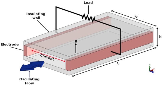
Figure 1.
Sketch of the operation principle of the alternate magnetohydrodynamic (MHD) generator.
In simple terms of order of magnitude, the power density in an MHD generator can be estimated as [20], where is the electric conductivity of the working fluid, B is the imposed magnetic field strength, and the average fluid velocity in the generator. Owing to the high electrical conductivity of liquid metals (of the order of S/m) which allows high-current, high-power density generation with lower flow velocities, are good candidates to be used as working fluids. In turn, with properly designed neodymium permanent magnets, magnetic field strengths of the order of T are feasible, while with an optimal design of the wave energy converter, it is possible to achieve an average fluid velocity of the order of m/s in the generator [21]. Therefore, this represents an estimated power density of the order of 4 MWm−3 which means that a compact generator with a volume of one liter could deliver a power output of the order of 4 KW.
An active branch of research in MHD electrical generation involves the use of plasma as a working fluid [20]. For instance, the use of an MHD generator coupled with a turbine has recently been analyzed in the search to increase the total efficiencies of fossil power plants [22]. In turn, inductive MHD plasma generators where the power transmission is allowed by magnetic induction, rather than by electrical contact, are also under development [23]. The coupling of an MHD inductive generator with a thermoacoustic resonator has also been investigated [24]. The principle behind this application involves the thermoacoustic effect which has been proposed to convert heat into acoustic energy, that is, the mechanical energy of the oscillating conducting fluid, which in turn, is converted to electrical energy through an MHD generator. This idea, that was originally proposed by Swift [25], has gained new interest in recent years mainly due to an interesting application that is currently being developed with the aim of supplying electric energy on space trips [26,27,28]. MHD generators can also act as mechanical energy harvesters capable of harnessing the mechanical energy from various environmental sources to convert it into electricity. With this aim, a novel MHD vortex generator has been reported which is based on the swirling flow of liquid metal through a cylindrical chamber under a strong magnetic field [29,30]. An advantage of this circular design is that it avoids the electrical energy end losses (end effects) that occur in duct MHD generators. As MHD generators are well suited for mechanical energy sources characterized by high forces, low characteristic frequencies, and small displacements [29], they have found their way in ocean wave energy harvesting. In fact, MHD generators can provide an excellent match to the mechanical impedance of ocean waves, which can hardly supply other wave power systems [31]. Several developments have been proposed over the years based on AC MHD generators. In 1992, a reciprocating MHD generator for ocean wave energy was first proposed by Rynne [32], where sea water passes through a duct under the presence of permanent magnets. However, due to the very poor electric conductivity of sea water, the power output is extremely small. In 2005, Koslover [33] patented a liquid metal MHD (LMMHD) power generation system coupled to a WEC and also performed a theoretical analysis of how to maximize the power output from the magnetohydrodynamic ocean wave energy converter by controlling the applied load impedance [34]. Another development was carried out by the Scientific Applications & Research Associates (SARA) who designed, built, and tested a 100 kW prototype LMMHD generator for wave energy conversion [35]. Although very scarce information is available, results reported that the efficiency from mechanical input to output electricity is about 50%. On the other hand, in the first decade of this century, the Institute of Electrical Engineering of the Chinese Academy of Sciences initiated an extensive program for developing a LMMHD generation system aimed at exploiting ocean wave energy. At the end of 2008, with a prototype tested in a demonstration facility with a hydraulic mechanism that generates a reciprocating motion to simulate a wave capture system, a device with a maximum output power of 3.35 kW and conversion efficiency of 68% was reported [31]. Another prototype that used mercury as a working fluid delivered a maximum output power of 160 W at a load factor of 0.5–0.6 with a magnetic field intensity of 0.5 T and a piston speed of 0.5 m/s [36]. With an optimized laboratory scale prototype of a LMMHD generator using U47 as the working fluid, a maximum output power of 1.1 kW was measured with a load resistance of 45 and magnetic flux density of 0.9 T, presenting a liquid metal speed in the generator of 0.5 m/s [21]. The effect of the properties of liquid metals with a low melting point on the performance of a LMMHD wave energy conversion prototype has also been analyzed [37]. The results show that the system has the largest output power and highest efficiency when NaK78 is the working liquid, considering the same external force and input work. The maximum output power of NaK78 resulted in about three times that of U-alloy47 and eight times that of mercury, while the average efficiency of NaK78 is two and four times that of U-alloy47 and mercury, respectively. Another independent numerical study analyzed the performance of a reciprocating liquid metal MHD generator for various external piston forces (regular, sinusoidal, and irregular) with the same three working fluids [38]. It was found that the power and electrical efficiency can be improved by choosing a liquid metal with low density and high electrical conductivity working under a relatively long period, considering the shape loss due to different cross-section areas between the MHD generator. Although this study also favors the use of NaK78 due to its performance (power and efficiency) for all kinds of forces, owing to its relatively low density and high electrical conductivity, safety issues may prevent the use of such a liquid metal in the ocean applications. In a more recent study [39], the importance of a low density working medium to reduce the damping of a power take-off (PTO) system was confirmed, since with the increase of electrical conductivity the damping force of the PTO system increases substantially and there is a maximum value for the power output. The requirement of a working medium with the characteristics of a low melting point, low viscosity, and non-toxic is emphasized. Different aspects that affect the performance of LMMHD generators have also been addressed in the literature. For instance, end effects caused by the short circuit of the currents at the edge of the electrodes of an MHD generator can lead to energy losses. Zhao et al. [40] found that the velocity in the MHD channel and the magnetic field gradient at the edge of the magnets are two key factors that greatly affect end effects and suggest the integration of an insulating vane and the smoothing of the gradient of the applied magnetic field to effectively suppress end currents and decrease energy losses. In a theoretical study, Dominguez-Lozoya et al. [41] analyzed the entrance flow region where the oscillatory fluid motion interacts with the nonuniform magnetic field, finding that non-linear effects in the boundary layer lead to the appearance of a pair of steady streaming vortices superimposed on the harmonic flow. Although the extension and intensity of the vortices grow as the magnetic field gradient increases, it was concluded that the disturbance created by the steady streaming vortices is not expected to affect the performance of the MHD generator. Another important issue is that due to the high conductivity of liquid metals and the characteristic low frequencies of wave motion, the output of LMMHD generators provides low voltage and high current. This may cause problems for reaching the output conditions required for common applications. In order to address this problem, Xu et al. [42] designed and simulated a power system for an LMMHD generator for the conversion of AC input into DC output, finding that the conversion efficiency of the AC-DC converter is mainly affected by the type of the rectifying device. Another large scale application of a LMMHD generator coupled to a WECs developed in China is aimed at recharging autonomous underwater vehicles (AUVs), which are limited by their on-board energy storage capability [43,44]. The conceptual design of the MHD wave energy underwater recharging platform for AUVs includes a heaving buoy, a reciprocating liquid metal MHD generator with an average output power of 4.4 kW, a power conversion unit, and an underwater induction power transmission system. In a recent paper, the performance analysis of a heaving float wave energy converter (WEC) coupled to a LMMHD generator was carried out, where the design of a 5 kW LMMHD-WEC prototype with a system efficiency of 27% was reported [45]. Results confirm that a key factor influencing the performance of a LMMHD-WEC system is the working fluid, along with wave motion characteristics, being possible to obtain the best performance by adjusting the load parameters.
Although the extensive development carried out mainly at the Institute of Electrical Engineering of the Chinese Academy of Sciences has covered a variety of relevant topics of MHD ocean wave energy conversion, the assessment of the coupling of a LMMHD generator to a WEC is not yet completed and more basic and technological research are required to determine the feasibility of using ocean wave energy to produce electricity through LMMHD generators. In addition, the Chinese research team has been focused on large scale developments and high power units, using mainly three liquid metals, namely, NaK78, U-alloy47, and mercury. However, LMMHD generators can also be of interest for small scale wave energy harvesting applications, for instance, as a source of electrical energy to feed oceanographic instrumentation. In this context, the assessment of Galinstan as working liquid metal is relevant mainly due to its non-toxic characteristics.
In this paper, we present the characterization of an alternate LMMHD generator at a laboratory scale that is intended to make use of the energy of marine waves for its conversion into electrical energy. This is the first step towards the development of a small-scale LMMHD power generator coupled to a WEC. One of the guidelines for the present design was the suitability to carry out precise measurements of both the flow dynamics within the MHD generator, as well as its electrical response. From the dynamic point of view, the oscillatory motion of the liquid metal in the MHD duct was measured using ultrasonic doppler velocimetry for different amplitudes and oscillation frequencies. For electrical characterization, the output current and voltage were measured for different operation conditions while an estimation of the electric power and efficiency was performed from experimental measurements. In a future contribution, the coupling of a LMMHD generator to a WEC will be addressed.
2. Methodology, Experimental Setup, and Operation
The experimental set up involved three main elements: The reciprocating system, which emulated the oscillatory motion of the marine waves transferred to the liquid metal; the oscillation duct where the oscillatory liquid metal was confined, including the MHD transducer that transformed the motion of the fluid into electricity delivered to an external load; and the measurement system used to characterize the flow pattern and the electrical performance of the device. The guideline for the design was to allow the fluid dynamics and electrical characterization of the MHD generator. The whole system was designed using CAD programs and the construction process was carried out with computer-controlled machine tools (CNC) to provide the highest possible precision.
The reciprocating system transforms the angular motion of an electric motor into a linear oscillatory motion with a zero-mean through a connecting rod-crank-sliding mechanism, driving the liquid metal in the oscillation duct consisting of a 75.5-cm long acrylic channel with a uniform rectangular cross section of 6 cm × 1.2 cm. Two permanent neodymium magnets of 8 cm × 12 cm, located at 35 cm from the edge of the piston, are placed at opposite parallel walls of a larger area which are electrically insulated, so that a nearly uniform transversal magnetic field is set within this zone, except in the fringing region near the edges of the magnets. A detailed measurement of the magnetic field strength of the neodymium magnets was performed using a Gaussmeter, mapping the whole magnet surface at the center plane of the duct. Permanent magnets were separated by a distance of 22 mm and with this configuration a maximum magnetic field strength of approximately 0.18 T at a distance of 11 mm from the surface of the magnets was found. Copper electrodes with a liquid metal contact area of 13 cm × 1.2 cm are allocated in the remaining parallel walls of the duct so that an external load can be coupled to them (see Figure 2). Eutectic alloy Gallium-Indium-Tin (Galinstan) was used as the working fluid whose density, kinematic viscosity, and electrical conductivity are, respectively, kg/m3, m2/s, and S/m.
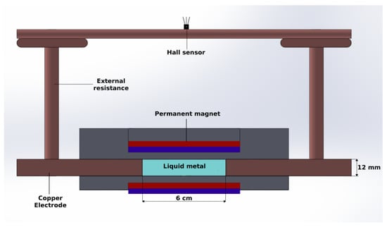
Figure 2.
Sketch of the cross-section of the generator in the transducer zone.
The oscillation frequency can vary in the range of 0.02–0.5 Hz, which comprises values found in waves of the Mexican coasts [46,47]. In turn, the amplitudes of the oscillating motion vary from 5 to 10 cm. At the extreme of the duct opposite to the location of the piston, there is an open area where the ultrasonic Doppler transducer is introduced in direct contact with the working fluid in order to measure the axial velocity component of the oscillatory flow. A general view of the experimental device is shown in Figure 3.
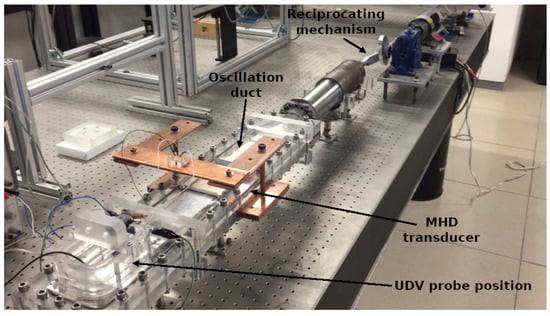
Figure 3.
Experimental device. UDV: Uultrasonic doppler velocimetry.
The performance of the device depends on the oscillation frequency and amplitude of the fluid, the magnitude and distribution of the applied magnetic field, the physical properties of the liquid metal and the external electrical load. Two important dimensionless parameters that can be used to characterize the MHD flow in the alternate generator are the oscillation Reynolds number and the Hartmann number, defined, respectively, as:
where is the flow oscillation frequency, h is half the distance between the walls normal to the magnetic field, and is the magnetic field strength in the geometric center of the generator. While characterizes the dimensionless oscillation frequency of the fluid, the square of compares the magnetic and viscous forces in the flow. Considering the spatial average at the mid plane of the duct, we have T as a characteristic magnetic field strength, therefore, the Hartmann number takes a fixed value of , confirming the dominance of magnetic forces over viscous forces in the region exposed to the magnetic field. In turn, accounting for the variation of the experimental forcing frequency and the characteristic length scale ( mm), the oscillation Reynolds number varies in the range = 14–300.
It can be shown that nonlinear effects in the oscillatory flow are of the order of , where:
is the oscillation amplitude parameter, G being the amplitude of the pressure gradient which can be deduced from the volumetric flow rate Q [41,48]. For the experimental conditions, the range of variation of R is found to be 0.003–0.84 and considering the variation of , it is found that , therefore, nonlinear effects resulted to be negligible under the experimental conditions and the flow remained laminar.
An important electrical parameter is the load factor, defined as [48]:
which relates the internal resistance of the generator, , with the load resistance, , and takes values from 0 to 1. The internal resistance assuming constant flow rate can be estimated as [48]:
where w is the separation between the electrodes and A is their area. corresponds to the short circuit condition where the load resistance is much smaller than the internal resistance () so that the current circulates without restriction through the circuit. In turn, the open circuit condition occurs when , where the load resistance is much larger than the internal resistance () causing the current to close its paths within the generator.
3. Flow Dynamics in the Oscillation Duct
The liquid metal impelled by the piston in the oscillation duct describes essentially an oscillatory motion with a zero mean that comprises regions exterior to the applied magnetic field, where the flow behaves hydrodynamically, and a region affected by the magnetic field where MHD effects are important. Owing to the prescribed experimental conditions, non-linear effects are negligible, therefore, the explored flow is in laminar regime. Since the motion of the liquid metal in the oscillation duct is mainly unidirectional, only the velocity component parallel to the symmetry axis of the duct was measured.
The axial flow velocity was recorded with an ultrasonic doppler velocimetry (UDV), using a UDV 3010 Signal Processing system with a transducer TR0810LS of 8 MHz [49]. A mechanism allowed the transducer to move along the width of the duct, so that the axial velocity can be measured in the central region as well as close to the lateral walls. To avoid reflections caused by acoustic waves bouncing in the metal face of the piston, measurements were made near the side walls of the channel by placing first the transducer in the normal direction to the main flow and then varying the direction of the transducer (acoustic axis) with a certain angle with respect to the main flow direction. By taking the projection in this direction, the axial velocity component was obtained.
Figure 4 shows the maps of the axial velocity component of the liquid metal as a function of the axial distance and time in open circuit conditions (). Three different oscillation frequencies are shown (, and ), while the Hartmann number () and the oscillation amplitude ( cm) remained fixed. The axial distance equal to zero corresponds to the location of the transducer while different colors represent the magnitude of the axial velocity. The red color (positive direction) indicates that the flow moves away from the transducer and the blue color (negative direction) indicates that the flow moves toward the transducer. The vertical alternating colored regions show that the axial velocity behaves in a periodic way. As the oscillation Reynolds number increases, the vertical alternating colored regions become narrower and more clearly defined. The region in between the black horizontal lines represents the location of the edges of the magnets, where electromagnetic effects are present.
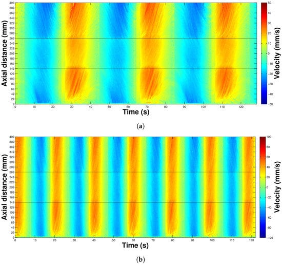
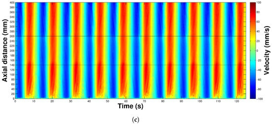
Figure 4.
UDV velocity maps in terms of the axial distance and time for , oscillation amplitude of 9.2 cm, and for different oscillation frequencies: (a) , (b) , and (c) .
Figure 5a shows the axial velocity component as a function of time at a distance of 15 mm from the side wall ( 15 mm) and at the axial distance 209 mm (which corresponds to the center of the magnets), for , amplitude of 9.2 cm, and different oscillation Reynolds numbers. It can be observed that the magnitude of the axial velocity increases as increases. Notice that the variation of involves also a phase shift. Figure 5b shows a comparison of the axial velocity profiles as a function of time at the center of the oscillation duct ( mm) in two axial positions, one at the hydrodynamic region ( mm) and the other at the mid point of the permanent magnets ( mm) for = 29.9, and amplitude of 9.2 cm. Since the Lorentz force reduces the velocity in the region influenced by the magnetic field, the velocity within this region is smaller than the velocity outside it (hydrodynamic region). In the present case, the reduction in the velocity is about 11.3%.

Figure 5.
(a) Axial velocity as a function of time at the fixed axial distance mm (center of the magnets) and at the fixed transversal position mm (15 mm from the lateral wall) for different oscillation Reynolds numbers. (b) Axial velocity component as a function of time for , at the center of the oscillation duct ( mm). The black line corresponds to an axial distance mm (at the mid point of the magnetic field region) and the red line corresponds to mm (far from the magnetic field region). In (a,b) and the oscillation amplitude was 9.2 cm.
Figure 6 shows the root mean square (RMS) values of the average axial velocity in the oscillation duct, obtained from the velocity profiles, as a function of the for and two oscillation amplitudes. It can be observed that the RMS value of the axial velocity component increases as increases.

Figure 6.
Root mean square (RMS) value of the average axial velocity at the transversal mid plane of the magnets as a function of for different oscillation amplitudes with .
4. Electrical Behavior of the LMMHD Generator
Evidently, the electrical response of the LMMHD generator is linked to the power source that drives the movement. Therefore, as a result of the reciprocating linear movement of the piston transmitted to the liquid metal, the output electrical signals, namely, the induced current and voltage, have an alternating behavior. The electrical performance of the generator depends on several physical and geometrical parameters that include the size (volume) of the generator, the oscillation frequency and amplitude of the liquid metal, the internal and external electrical resistance of the generator, the strength and distribution of the applied magnetic field, and the physical properties of the liquid metal. Once the design of the prototype was defined, some parameters remained fixed such as the size and internal resistance of the generator, the applied magnetic field and the properties of the liquid metal. The electrical response of the generator was then explored by varying the oscillation frequency and amplitude of the liquid metal as well as the external electric resistance (load factor). The variation of these parameters is, in turn, restricted by the limitations of the experimental prototype.
The electrical output conditions of the LMMHD generator involve low voltages and high currents, then, it is necessary to use non-conventional measurement methods to characterize its electrical behavior, since it is practically impossible to get reliable measurements with ordinary devices. To overcome this complication, the current was inferred from a Hall effect sensor (Allegro A1324 with a sensitivity of 5 mV/G), where its output voltage was related to the induced magnetic field in a conductor (a variable electric load) through which the electric current of the MHD generator passed. The calibration of the Hall effect sensors and the measurement of the electrical resistance of the variable loads were carefully carried out to guarantee the reliability of the output electrical measurements. The output voltage can then be estimated using Ohm’s law by means of the induced current and the electric resistance of the external load. With the aim of varying the load factor of the generator, materials with different electrical resistances were used. The internal resistance of the generator measured experimentally is equal to . In turn, the total load resistance () is the sum of the resistance of all the components of the external load, which includes a fixed electric load plus a variable load. The variable electric resistance consisted of three metallic bars of different materials (copper, aluminum, and steel) so that it was possible to obtain values of the load factor K of 0.88, 0.916, 0.920, and 0.978 [48].
Figure 7a,b, respectively, show the induced current and voltage as a function of time for different values of the oscillation Reynolds number. The oscillation amplitude was 9.2 cm while the load factor and Hartmann number correspond to and , respectively. First, notice that induced currents, inferred from the output of the Hall effect sensor, are of the order of magnitude of amperes (A) while induced voltages remain in the order of millivolts (mV). It can also be observed that the amplitude of induced currents and voltages increases as the oscillation frequency increases, while a phase shift also appears with the variation of this parameter. In both figures, the signal corresponding to the smaller frequency () shows a slight deformation with respect to a pure sinusoidal signal that could be due to perturbations introduced by the reciprocating system.
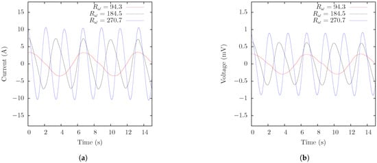
Figure 7.
Induced output current (a) and induced output voltage (b) as functions of time for different oscillation Reynolds numbers with , and an oscillation amplitude of 9.2 cm.
Figure 8 shows the RMS value of the induced current and voltage as functions of the oscillation Reynolds number for different load factors with and an oscillation amplitude of cm. It can be observed that current and voltage increase almost linearly with respect to the oscillation frequency. For the induced current, the fastest growth is found for the smallest load factor explored () while the slowest corresponds to the higher load factor (). As expected, this behavior is inverted for the induced voltage although differences in the growth rate for different load factors are rather small. For the lowest load factor explored (), the highest RMS values for the induced current and voltage are A and mV, respectively.
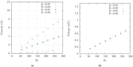
Figure 8.
RMS values of the induced output current (a) and voltage (b) as functions of the oscillation Reynolds numbers for different load factors with and an oscillation amplitude of cm.
The performance of the alternate LMMHD generator is characterized to a large extent by the output electric power which can be obtained from the product of the induced current and induced voltage. Figure 9a shows the output electric power as a function of time for different oscillation Reynolds numbers with , , and an oscillation amplitude of 9.2 cm. It can be observed that the amplitude of the output power increases as increases and reaches around 10 mW for the highest value shown (). Note also that the peak amplitude presents slight variations. The RMS value of the output electric power is shown in Figure 9b as a function of the oscillation Reynolds number for different load factors with and an oscillation amplitude of cm. A quadratic variation with the oscillation Reynolds number is found, the fastest growth corresponding to the largest value ().

Figure 9.
(a) Output electric power as a function of time for different oscillation Reynolds numbers with . (b) RMS values of the electric output power as a function of the oscillation Reynolds number for different load factors. and the oscillation amplitude is 9.2 cm.
The electrical characterization of the alternate LMMHD generator requires the calculation of efficiency. The electrical isotropic efficiency is defined as the ratio of the output electric power, , and the flow power or mechanical power, , required to overcome the Lorentz force exerted on the fluid within the magnetic field, integrated over the total volume V of the generator and over a whole time period (or an integer number of periods) [20,50], that is:
where , , and are the electric current density field, electric field, and velocity field, respectively. Note that the integral in the numerator is the product of the current and voltage and can be estimated directly from the experimental RMS values. On the other hand, it was not possible to obtain the flow power directly from the experiments, therefore, an alternative estimation based on the following expression was used:
where the analytical expressions for and based on a simplified analytical model of the generator and fed with experimental values were used [48].
Figure 10a shows the electrical efficiency estimated using expression (1) as a function of the oscillation Reynolds number for different values of the load factor with and oscillation amplitude of 9.2 cm. It can be observed that the highest efficiency () is obtained for the smallest load factor explored () while the lowest efficiency () corresponds to the largest load factor (). For each load factor, the efficiency remains practically constant in the whole range of , although a very slight increase is found with this parameter. Figure 10b shows the isotropic efficiency as a function of the load factor for , , and oscillation amplitude of 9.2 cm. The symbols represent the experimental data while the black line corresponds to a data fit. Only one value of is presented due to the very small change of the efficiency with respect to this parameter, therefore, this curve is essentially the same for any other of the explored values of . It can be observed that the maximum efficiency is obtained for .
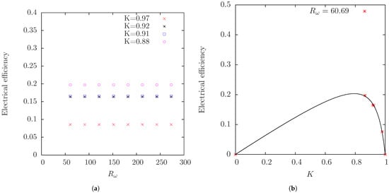
Figure 10.
(a) Electrical efficiency as a function of the oscillation Reynolds number for different load factors. (b) Electrical efficiency as a function of the load factor, K, for . In (a,b) and the oscillation amplitude is 9.2 cm.
When compared with the values of output electric power and electrical efficiency predicted by a simplified analytical model [48,50], the values obtained experimentally for the output power and the electrical efficiency are approximately 50% lower. This reflects in part the idealizations introduced in the model which considers the flow in the MHD generator as two-dimensional and under a completely uniform magnetic field. The existence of additional friction losses, not considered explicitly in the model, as well as contact resistance effects between the copper walls and liquid metal, affect the performance of the generator. In turn, the non-homogeneity of the magnetic field and the finite size of the magnets, originate modifications in the flow field [41], as well as in the electrical response of the device. In particular, the abrupt variation of the magnetic field at the edges of the permanent magnets and finite size of the electrodes give rise to end-effects which divert the induced electric currents out of the electrode area forming short-circuited loops outside the generation zone [37].
5. Concluding Remarks
In the present work, the experimental characterization of a liquid metal magnetohydrodynamic generator which has the potential of converting useful energy from marine waves into electricity was carried out. As direct power conversion systems, MHD generators present an alternative to linear generators, the main difference with these devices being the use of a fluid as conducting medium. Moreover, MHD generators are able to work at low frequencies, matching the frequencies of ocean waves. As mechanical energy harvesters, LMMHD generators are capable of harnessing in a suitable and efficient way, ocean wave energy to convert it into electricity, particularly for small-scale applications. Motivated in the understanding and modeling of the physical phenomena involved in the conversion process and the scarce experimental information on the performance of small-scale devices, we reported the construction and experimental characterization of a prototype at a laboratory scale of an alternate MHD generator that uses galinstan as a working fluid.
To emulate the oscillatory wave motion, a device that allows to transform the rotary movement of an electric motor into a linear motion transferred to the liquid metal confined in the oscillation duct was designed. The LMMHD transducer allows the variation of the oscillation frequency and amplitude, as well as the external electric load. The analysis of the oscillatory liquid metal MHD flow was carried out using a UDV system which allowed the measurement of the axial velocity component of the flow for different oscillation frequencies and oscillation amplitudes. To the best of our knowledge, UDV measurements of the liquid metal flow in an MHD generator have not been reported before. The braking effect caused by Lorentz forces when the liquid metal flows through the zone affected by the applied magnetic field was also detected. Moreover, for the explored range of governing parameters, the average axial velocity increased in a linear way with respect to the oscillation Reynolds number.
As LMMHD generators deliver low output voltages and high output currents, typical measurement techniques are useless, therefore, in this prototype the electric current flowing in the external load was inferred from a Hall effect sensor while the load resistance was measured using a multimeter and applying the 4-wire technique. It was found that the RMS values of the current and voltage increased in a linear way as the oscillating Reynold number increased, while the output electric power, being the product of the current and voltage, increased quadratically as the oscillating Reynolds number increased. Due to the smallness of the internal resistance of the generator, it was difficult to get load factor values close to where the highest output power was obtained (when the load resistance equaled the internal resistance). Maximum RMS values around 5 mW were reached for the lowest load factor explored () and a high oscillation Reynolds number of 273. In turn, estimations of the isotropic efficiency were obtained, where the mechanical power was calculated with an analytical function. The highest isotropic efficiency estimated experimentally for was about 20% in the whole range of explored. This is much lower than the efficiency predicted by a simplified analytical model [48,50] due to several factors. In the first place, the analytical model is two-dimensional and assumes that the applied magnetic field is everywhere uniform which is far from reality. In fact, the non-homogeneity of the magnetic field and the finite length of the electrodes cause the end-effects of the generator, which are responsible for the biggest losses in the generator. It has to be mentioned that unlike the large scale systems developed at the Institute of Electrical Engineering of the Chinese Academy of Sciences, the LMMHD generator presented in this work has not been designed to provide an optimized electrical performance but to allow, on the one hand, a detailed measurement of the oscillatory velocity of the liquid metal through the UDV technique, which helps to describe the flow dynamics inside the generator and, on the other, to acquire reliable data of the output voltage and current for characterizing the performance of the small scale device. Furhtermore, our results provide information of the effects of the properties of galinstan on the performance of a reciprocating LMMHD generator, a working fluid that has not been tested before for this application.
Currently, a new experimental prototype able to operate in more realistic conditions is under construction with the objective of testing a LMMHD generator in a wave channel avoiding the reciprocating system used in the laboratory prototype. This implies coupling the generator to a wave energy converter, that will be responsible for transferring the oscillating motion of the waves generated in the channel to the alternate LMMHD generator. The new design of the oscillation duct introduces modifications which will allow a better performance of the generator. In particular, a geometric modification of the oscillation duct that increases the liquid metal velocity and reduces the losses due to end-effects in the alternate LMMHD generator are considered. These are important aspects to be considered for increasing the output power and electric efficiency of the generator.
Although many challenges have still to be overcome for the use of ocean wave energy through MHD generators, the present work tested the feasibility of an alternate LMMHD generator at a laboratory scale, providing experimental results that will be of relevance for future designs. A more wide assessment can set AC LMMHD generators as a suitable alternative to convert ocean wave energy into electricity on a small scale. For instance, the power supply to offshore scientific instrumentation could be considered as an interesting application. If required, higher output power could be reached by coupling several generators. Among the remaining challenges is the development of a conversion system for transforming the electrical output of the alternate LMMHD generator, characterized by high currents and low voltages, to the standard requirements of conventional electric devices. It is expected that results obtained in the present work will set the basis for future research and development leading to a complete assessment of MHD technology for wave energy conversion.
Author Contributions
Conceptualization, J.C.D.-L., S.C., D.R.D., R.Á.-Z. and E.R.; methodology, J.C.D.-L. and D.R.D.; validation, J.C.D.-L. and D.R.D.; formal analysis, J.C.D.-L. and S.C.; investigation, J.C.D.-L., S.C. and R.Á.-Z.; data curation, J.C.D.-L.; writing–original draft preparation, J.C.D.-L.; writing–review and editing, S.C. and E.R.; supervision, S.C., R.Á.Z. and E.R.; project administration, S.C.; funding acquisition, S.C., R.Á.Z. and E.R. All authors have read and agreed to the published version of the manuscript.
Funding
This research was funded by Centro Mexicano de Innovación en Energía Océano, CEMIE-Océano SENER-CONACYT grant number 249795 and by CONACYT under Project 240785.
Institutional Review Board Statement
Not applicable.
Informed Consent Statement
Not applicable.
Data Availability Statement
Data supporting results can be found at: http://132.248.9.195/ptd2019/febrero/0785811/Index.html.
Conflicts of Interest
The authors declare no conflict of interest. The funders had no role in the design of the study; in the collection, analyses, or interpretation of data; in the writing of the manuscript, or in the decision to publish the results.
Abbreviations
The following abbreviations are used in this manuscript:
| MHD | Magnetohydrodynamics |
| LMMHD | Liquid metal magnetohydrodynamics |
| WEC | Wave energy converter |
| AC | Alternate current |
| PTO | Power take-off |
References
- Rusu, E.; Onea, F. A review of the technologies for wave energy extraction. Clean Energy 2018, 2, 10–19. [Google Scholar] [CrossRef]
- Electricity Information: Overview; International Energy Agency: Paris, France, 2020.
- Titah-Benbouzid, H.; Benbouzid, M. An up-to-date technologies review and evaluation of wave energy converters. Int. Rev. Electr. Eng. 2015, 10, 52–61. [Google Scholar] [CrossRef]
- Falcão, A.F.O. Wave energy utilization: A review of the technologies. Renew. Sustain. Energy Rev. 2010, 14, 899–918. [Google Scholar] [CrossRef]
- Esteban, M.D.; Lopez-Gutierrez, J.S.; Negro, V. Classification of wave energy converters. Recent Adv. Petrochem. Sci. 2017, 2, 5555. [Google Scholar]
- Esteban, M.D.; Lopez-Gutierrez, J.S.; Negro, V.; Laniña, M.; Muñoz-Sánchez, P. A new classification of wave energy converters used for selection of devices. Recent Adv. Petrochem. Sci. 2018, 85, 1286–1290. [Google Scholar] [CrossRef]
- Szabo, L.; Oprea, C.; Viorel, I.; Biro, K.A. Novel Permanent Magnet Tubular Linear Generator for Wave Energy Converters. In Proceedings of the 2007 IEEE International Electric Machines &Drives Conference, Antalya, Turkey, 3–5 May 2007; pp. 983–987. [Google Scholar]
- Polinder, H.; Mueller, M.; Scuotto, M.; de Sousa Prado, M.G. Linear generator systems for wave energy conversion. In Proceedings of the 7th European Wave and Tidal Energy Conference, Porto, Portugal, 11–13 September 2007. [Google Scholar]
- Faiad, A.A.; Gowad, I.A. Linear generator technologies for wave energy conversion applications: A review. In Proceedings of the 2018 53rd International Universities Power Engineering Conference (UPEC) IEEE, Glasgow, UK, 4–7 September 2018. [Google Scholar]
- Faiz, J.; Nematsaberi, A. Linear electrical generator topologies for direct-drive marine wave energy conversion—An overview. IET Renew. Power Gener. 2017, 11, 1163–1176. [Google Scholar] [CrossRef]
- López, I.; Andreu, J.; Ceballos, S.; Martínez de Alegría, I.; Kortabarria, I. Review of wave energy technologies and the necessary power equipment. Renew. Sustain. Energy Rev. 2013, 27, 413–434. [Google Scholar] [CrossRef]
- Salter, S.H.; Taylor, J.R.M.; Caldwell, N.J. Power conversion mechanisms for wave energy. Proc. Inst. Mech. Eng. Part J. Eng. Marit. Environ. 2002, 216, 1–27. [Google Scholar] [CrossRef]
- Lagoun, M.S.; Benalia, A.; Benbouzid, M.E.H. Ocean wave converters: State of the art and current status. In Proceedings of the 2010 IEEE International Energy Conference, Manama, Bahrain, 18–22 December 2010; pp. 636–641. [Google Scholar]
- Shami, E.A.; Zhang, R.; Wang, X. Point Absorber Wave Energy Harvesters: A Review of Recent Developments. Energies 2019, 12, 47. [Google Scholar] [CrossRef]
- Maria-Arenas, A.; Garrido, A.J.; Rusu, E.; Garrido, I. Control Strategies Applied to Wave Energy Converters: State of the Art. Energies 2019, 12, 3115. [Google Scholar] [CrossRef]
- Hodgins, N.; Keysan, O.; McDonald, A.S.; Mueller, M.A. Design and testing of a linear generator for wave-energy applications. IEEE Trans. Ind. Electron. 2012, 59, 2094–2103. [Google Scholar] [CrossRef]
- Kakosimos, P.E.; Tsampouris, E.M.; Kimoulakis, N.M.; Kladas, A. Overview of the Alternative Topologies of Linear Generators in Wave Energy Conversion Systems. Mater. Sci. Forum 2012, 721, 281–286. [Google Scholar] [CrossRef]
- Plummer, A.R.; Hillis, A.J.; Perez-Collazo, C. Power Systems. In Wave and Tidal Energy; Greaves, D., Iglesias, G., Eds.; Wiley: New York, NY, USA, 2018; Charpter 6; p. 191. [Google Scholar]
- Tetu, A. Power Take-Off Systems for WECs. In Handbook of Ocean Wave Energy; Pecher, A., Kofoed, J.P., Eds.; Springer: Berlin/Heidelberg, Germany, 2017; Charpter 8; p. 203. [Google Scholar]
- Rosa, R.J. Magnetohydrodynamic Energy Conversion; Hemisphere: New York, NY, USA, 1987. [Google Scholar]
- Liu, B.; Li, J.; Peng, Y.; Zhao, L.; Li, R.; Xia, Q.; Sha, C. Performance Study of Magnetohydrodynamic Generator for Wave Energy. In Proceedings of the 24th International Offshore and Polar Engineering Conference, Busan, Korea, 15–20 June 2014; pp. 907–910. [Google Scholar]
- Lee, G.H.; Kim, H.R. The variable analysis of an MHD generator with electrical output of 10 kW for application to bi-plant method electricity generation. Int. J. Energy Res. 2020, 44, 8125–8132. [Google Scholar] [CrossRef]
- Carcangiu, S.; Forcinetti, R.; Montisci, A. Simulink model of an iductive MHD generator. Magnetohydrodynamics 2017, 53, 255–266. [Google Scholar] [CrossRef]
- Alemany, A.; Carcangiu, S.; Forcinetti, R.; Montisci, A.; Roux, J.P. Feasibility analysis of an MHD inductive generator coupled with a thermoacoustic resonator. Magnetohydrodynamics 2015, 51, 531–542. [Google Scholar] [CrossRef]
- Swift, G.W. A liquid-metal magnetohydrodynamic acoustic transducer. J. Acoust. Soc. Am. 1988, 83, 350–361. [Google Scholar] [CrossRef]
- Mirhoseini, S.M.H.; Alemany, A. Analytical study of thermoacoustic MHD generator. Magnetohydrodynamics 2015, 51, 519–530. [Google Scholar] [CrossRef]
- Gailitis, A.; Brekis, A. Equivalent circuit approach for acoustic MHD generator. Magnetohydrodynamics 2020, 56, 3–13. [Google Scholar]
- Brekis, A.; Freibergs, J.E.; Alemany, A. Initial experimental tests on space trips facility of thermoacoustic-to-MHD energy converter. Magnetohydrodynamics 2020, 56, 255–267. [Google Scholar]
- Panchadar, K.; West, D.; Taylor, J.A.; Krupenkin, T. Mechanical energy harvesting using a liquid metal vortex magnetohydrodynamic generator. Appl. Phys. Lett. 2019, 114, 093901. [Google Scholar] [CrossRef]
- West, D.; Taylor, J.A.; Krupenkin, T. Alternating current liquid metal vortex magnetohydrodynamic generator. Energy Convers. Manag. 2020, 223, 113223. [Google Scholar] [CrossRef]
- Li, J.; Peng, Y.; Liu, B.; Sha, C.; Zhao, L.; Xu, Y.; Li, R.; Li, X. Analysis of liquid metal MHD wave energy direct conversion system. In Proceedings of the 7th European Wave and Tidal Energy Conference (ISOPE), Vancouver, BC, Canada, 11–13 September 2007; pp. 388–392. [Google Scholar]
- Rynne, T.M. Ocean Wave Energy Conversion System. U.S. Patent 5136173A, 4 August 1992. [Google Scholar]
- Koslover, R.A.; Law, R.C. Modular Liquid-Metal Magnetohydrodynamic (LMMHD) Power Generation Cell. U.S. Patent 7166927B2, 23 January 2007. [Google Scholar]
- Altshuller, D.A.; Koslover, R.A. Optimal Control of the Magnetohydrodynamic Ocean Wave Energy Converter: Theory. In Proceedings of the 2005 International Conference Physics and Control, St. Petersburg, Russia, 24–26 August 2005; pp. 126–129. [Google Scholar]
- Khaligh, A.; Onar, O.C. Energy Harvesting: Solar, Wind, and Ocean Energy Conversion Systems; CRC Press: Boca Raton, FL, USA, 2009; Available online: http://www.sara.com (accessed on 12 January 2017).
- Li, J.; Peng, Y.; Liu, B.; Sha, C.; Zhao, L.; Xu, Y.; Li, R.; Li, X. Preliminary experimental study on LMMHD wave energy conversion system. In Proceedings of the 20th International Offshore and Polar Engineering Conference, Beijing, China, 20–25 June 2010; pp. 907–910. [Google Scholar]
- Zhao, L.; Peng, Y.; Sha, C.; Li, R.; Xu, Y.; Liu, B.; Li, J. Effect of Liquid Metal Characteristics on Performance of LMMHD Wave Energy Conversion System. In Proceedings of the 19th International Offshore and Polar Engineering Conference, Osaka, Japan, 21–26 June 2009. [Google Scholar]
- Hu, L.; Kobayashi, H.; Okuno, Y. Performance of a liquid metal MHD power generation system for various external forces. In Proceedings of the 12th International Energy Conversion Engineering Conference, Cleveland, OH, USA, 28–30 July 2014; p. 3558. [Google Scholar]
- Liu, Y.; Liu, B.; Peng, A. Effect of Working Medium Property on Performance of Heaving Float Wave Energy Converter with Liquid Metal MHD Generator. In Proceedings of the 27th International Ocean and Polar Engineering Conference, San Francisco, CA, USA, 25–30 June 2017. ISOPE-I-17-715. [Google Scholar]
- Zhao, L.; Peng, Y.; Sha, C.; Li, R.; Xu, Y.; Liu, B.; Li, J. End effect of liquid metal magnetohydrodynamic generator in wave energy direct conversion system. In Proceedings of the 2009 International Conference on Sustainable Power Generation and Supply IEEE, Nanjing, China, 6–7 April 2009; pp. 1–6. [Google Scholar]
- Domínguez-Lozoya, J.C.; Perales, H.; Cuevas, S. Analysis of the oscillatory liquid metal flow in an alternate MHD generator. Revista Mexicana de FíSica 2019, 65, 239–250. [Google Scholar] [CrossRef]
- Xu, Y.; Bai, J.; Peng, Y.; Li, R.; Zhao, L.; Sha, C.; Wei, W.; Liu, B.; Li, J. Study on power converting system of liquid metal MHD generator driven by wave energy. Appl. Mech. Mater. 2012, 229–231, 1052–1055. [Google Scholar] [CrossRef]
- Zhao, L.Z.; Ye, H.L.; Peng, A.W.; Zhang, Q.H.; Xia, Q.; Liu, B.L.; Li, J.; Wang, F.; Li, R. MHD wave energy underwater recharging platforms for AUVs. In Proceedings of the 26th International Ocean and Polar Engineering Conference, Rhodes, Greece, 26 June–1 July 2016; pp. 480–483. [Google Scholar]
- Zhang, Q.; Xia, Q.; Peng, A.; Zhao, L. Design of PCS for MHD wave energy underwater recharging platforms. In Proceedings of the 26th International Ocean and Polar Engineering Conference, Rhodes, Greece, 26 June–1 July 2016; pp. 484–490. [Google Scholar]
- Liu, Y.; Liu, B.; Liu, M.; Peng, A. Design and Performance Analysis on 5 kW Prototype Device of Heaving Float Wave Energy Conversion with Liquid Metal MHD Generator. In Proceedings of the 28th International Ocean and Polar Engineering Conference, Sapporo, Japan, 10–15 June 2018; pp. 712–718. [Google Scholar]
- Ruiz, G.; Silva, R.; Rivillas, G.; Posada, G.; Pérez, D.; Mendoza, E. Atlas de clima marítimo para las vertientes atlántica y pacífica del litoral mexicano. In Proceedings of the XXIII Latinoamerican Hydraulics Congress, Cartagena de Indias, Colombia, 1–5 September 2008. [Google Scholar]
- Ruiz, G.; Mendoza, E.; Silva, R.; Posada, G.; Pérez, D.; Rivillas, G.; Escalante, E.; Ruiz, F. Caracterización del régimen de oleaje y viento de 1948–2007 en el litoral mexicano. Ingeniería del Agua 2009, 16, 51–64. [Google Scholar] [CrossRef][Green Version]
- Domínguez-Lozoya, J.C. Electric Magnetohydrodynamic Generator for Wave Energy Conversion. Ph.D. Thesis, National Autonomous University of Mexico, Temixco, Morelos, Mexico, 2019. [Google Scholar]
- Signal Processing. DOP 3000/3010 User Manual. 2015. Available online: http://www.signal-processing.com (accessed on 5 January 2021).
- Ibáñez, G.; Cuevas, S.; López de Haro, M. Optimization analysis of an alternate magnetohydrodynamic generator. Energy Conv. Manag. 2002, 43, 1757–1771. [Google Scholar] [CrossRef]


Publisher’s Note: MDPI stays neutral with regard to jurisdictional claims in published maps and institutional affiliations. |
© 2021 by the authors. Licensee MDPI, Basel, Switzerland. This article is an open access article distributed under the terms and conditions of the Creative Commons Attribution (CC BY) license (https://creativecommons.org/licenses/by/4.0/).