Review

Sustainable Aviation Electrification: A Comprehensive Review of Electric Propulsion System Architectures, Energy Management, and Control

by
Jinning Zhang
1,2,*,
Ioannis Roumeliotis
1 and
Argyrios Zolotas
2
1
Centre for Propulsion, School of Aerospace, Transport and Manufacturing, Cranfield University, Bedfordshire MK43 0AL, UK
2
Centre for Autonomous and Cyber-physical Systems, School of Aerospace, Transport and Manufacturing, Cranfield University, Bedfordshire MK43 0AL, UK
*
Author to whom correspondence should be addressed.
Sustainability 2022, 14(10), 5880; https://doi.org/10.3390/su14105880
Submission received: 6 April 2022 / Revised: 2 May 2022 / Accepted: 9 May 2022 / Published: 12 May 2022

Abstract

:
The civil aviation sector plays an increasingly significant role in transportation sustainability in the environmental, economic, and social dimensions. Driven by the concerns of sustainability in the aviation sector, more electrified aircraft propulsion technologies have emerged and form a very promising approach to future sustainable and decarbonized aviation. This review paper aims to provide a comprehensive and broad-scope survey of the recent progress and development trends in sustainable aviation electrification. Firstly, the architectures of electrified aircraft propulsion are presented with a detailed analysis of the benefits, challenges, and studies/applications to date. Then, the challenges and technical barriers of electrified aircraft propulsion control system design are discussed, followed by a summary of the control methods frequently used in aircraft propulsion systems. Next, the mainstream energy management strategies are investigated and further utilized to minimize the block fuel burn, emissions, and economic cost. Finally, an overview of the development trends of aviation electrification is provided.

1. Introduction

The global aircraft fleet consumes over 7% of oil products (276 million tons of jet fuel) and produces 2.7% of energy-consumption-related CO2 emissions due to in-flight combustion. Furthermore, the global aviation demand is anticipated to grow at around 4.8% annually [1]. By the year 2050, a greater than 60% increase in global commercial air travel seat miles and a 38% increase in energy use are projected by the U.S. Energy Information Administration, with corresponding CO2 emissions projections of 209 million metric tons CO2e [2]. Thus, it is critical to reduce the environmental footprint of the aviation sector, and the civil aviation sector plays an increasingly significant role in transportation sustainability in the environmental, economic, and social dimensions. The major organizations and research councils have all published pathways for sustainable aviation decarbonization to reduce aviation-related pollutant emissions. For example, the NASA ‘N+3′ strategic implementation plan aims for −75% NOx emissions, −70% fuel burn, and −55 dB noise at the airport boundary in the year 2035 [3], and Flightpath 2050 targets a 75% reduction in CO2 emissions per passenger kilometer and a 90% reduction in NOx emissions relative to the technology level of the year 2000 [4]. However, the potential efficiency improvements achieved by conventional technology progress in airframes, structure, propulsion, and air-traffic management are already reaching a plateau. Driven by the concerns of environmental sustainability in the aviation sector, electrified aircraft propulsion technologies have emerged and have been identified as the most promising approach to realize sustainable and decarbonized aviation.
Many historical surveys have been published to provide a mature insight into electrified aircraft propulsion systems. For example, the existing potential and forecasted progress of aircraft hybrid electric architectures and their impact on the environment are surveyed in [5]. The recent progress, opportunities, and challenges of conceptual design and the technical advances of electrical system components are presented in [6], along with a discussion of the aircraft-level effects of electrification and the emerging problem of thermal management. Furthermore, the research work and development trends of conceptual design, preliminary sizing, and multidisciplinary optimization frameworks are comprehensively reviewed in [1], which also includes original and detailed assessments of regulations, certifications, and infrastructure. Furthermore, a life-cycle-oriented sustainability assessment of emerging aircraft technologies is investigated in [7] to identify these hotspots and problem shifts and provide further guidance for actions aimed at sustainable aviation development at an early stage. Additionally, technical advances in aviation electrification are explored to enhance strategy research and development investment analysis in [8].
This paper aims to provide a comprehensive and broad-scope survey of the recent progress and development trends in aviation electrification. In Section 2, the major architectures of electrified aircraft propulsion systems are presented from the perspectives of concepts, benefits, challenges, and studies/applications to date, and we further identify the performance requirements of the electrical system components. Section 3 discusses the challenges and technical barriers of the control system design of electrified aircraft propulsion systems and then summarizes the mainstream control techniques for aircraft propulsion systems. Next, the research gap on hybrid electric aircraft energy management strategies is discussed in Section 4, followed by a review of the recent progress in energy management strategy research. Finally, Section 5 presents an overview of the development trends of aviation electrification.

2. Electrified Aircraft Propulsion System Architectures

Electric propulsion architectures are generally classified as: all-electric, series hybrid electric, parallel hybrid electric, and turboelectric [9]. In this section, each architecture will be introduced individually from the perspectives of concepts, benefits, challenges, and studies/applications to date.

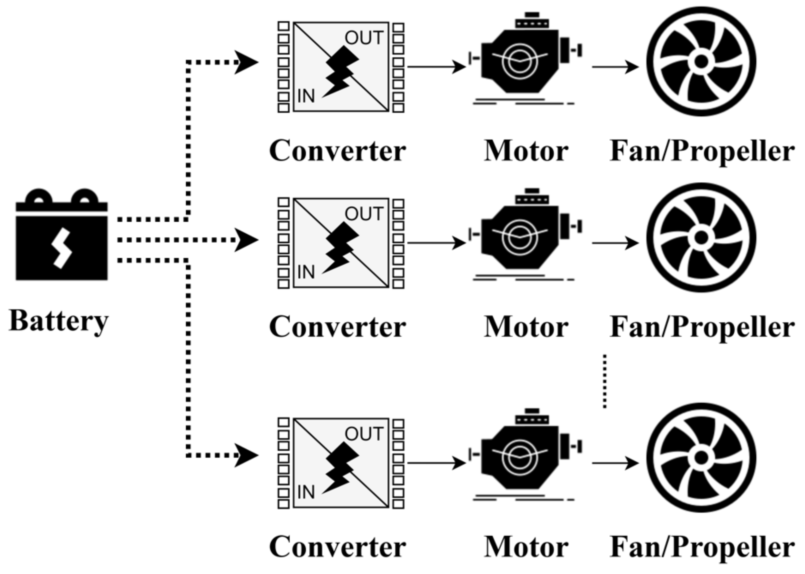
2.1. All-Electric Architecture

In all-electric propulsion architecture, batteries are the only energy source for the propulsion systems, as shown in Figure 1. The all-electric configuration is a high-efficiency energy conversion system and is the only candidate that has the potential to achieve zero emissions [10].
All-electric aircraft are identified as a feasible and cost-competitive approach to reduce the environmental impacts of short-haul flights, including vertical take-off and landing aircraft (eVTOLs) [11,12], commuter aircraft [13], rotorcraft [14,15], and general aviation airplanes. The key applications and studies to date are summarized in Table 1. The potential benefits that can be exploited from the global aircraft fleet are critically dependant on battery-pack technical advances [16]. All-electric aircraft with a battery-pack specific energy of 800 Wh/kg enable a flight mission range of up to 600 nmi, which can cover half of all aircraft departures. At this stage, NOx emissions at airport areas can be significantly mitigated by 40%, and block fuel burn and direct CO2 emissions can be reduced by 15%. To reach cost effectiveness with conventional aircraft, carbon taxes and batteries should be below USD 100 per kWh [17]. To enable a flight mission of 900 nmi with an all-electric propulsion system, the battery specific energy is required to reach 1200 Wh/kg [18].
The Committee on Propulsion and Energy Systems to Reduce Commercial Aviation Carbon Emissions identified the electrical system component performance requirements for all-electric propulsion systems, as shown in Table 2 [10].

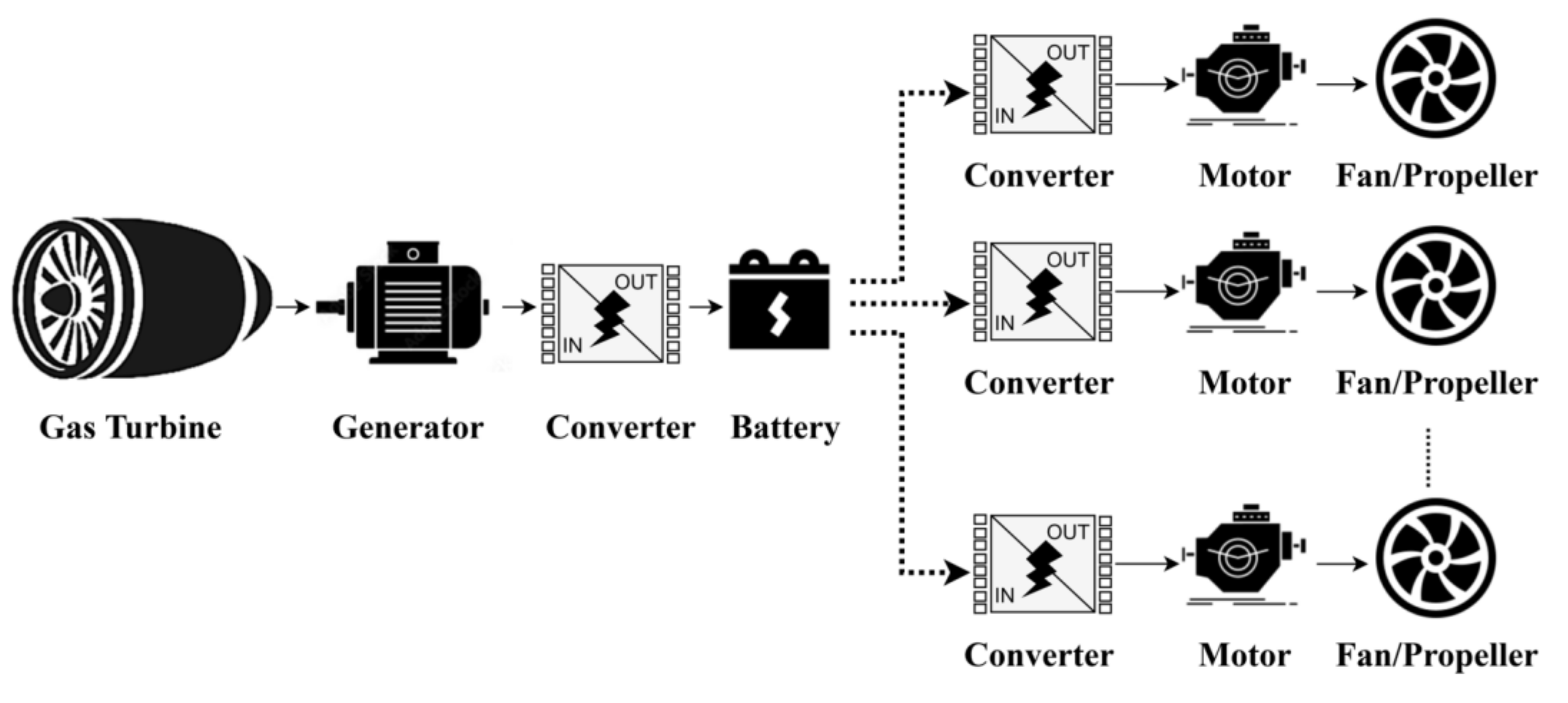
2.2. Series Hybrid Electric Architecture

The series hybrid electric architecture is presented in Figure 2. It is normally made compatible with distributed propulsion by using multiple relatively small electric motors and propellers/fans [10]. In series configurations, the fans/propellers are driven by electric motors, and the electrical power is either from a gas-turbine-driven generator or from a battery energy storage source. Because of the electrical power conversion and the transmission system, the operation of the gas turbine can be decoupled from fans/propellers, which enables the gas turbine to operate at its maximum efficiency. However, in series-hybrid electric propulsion systems, the electric motors should provide all of the propulsive power. Consequently, the electric motors need to be the right size to achieve their maximum power, which will increase the mass and volume of the propulsion system [30]. A summary of series hybrid electric architecture studies is provided in Table 3.

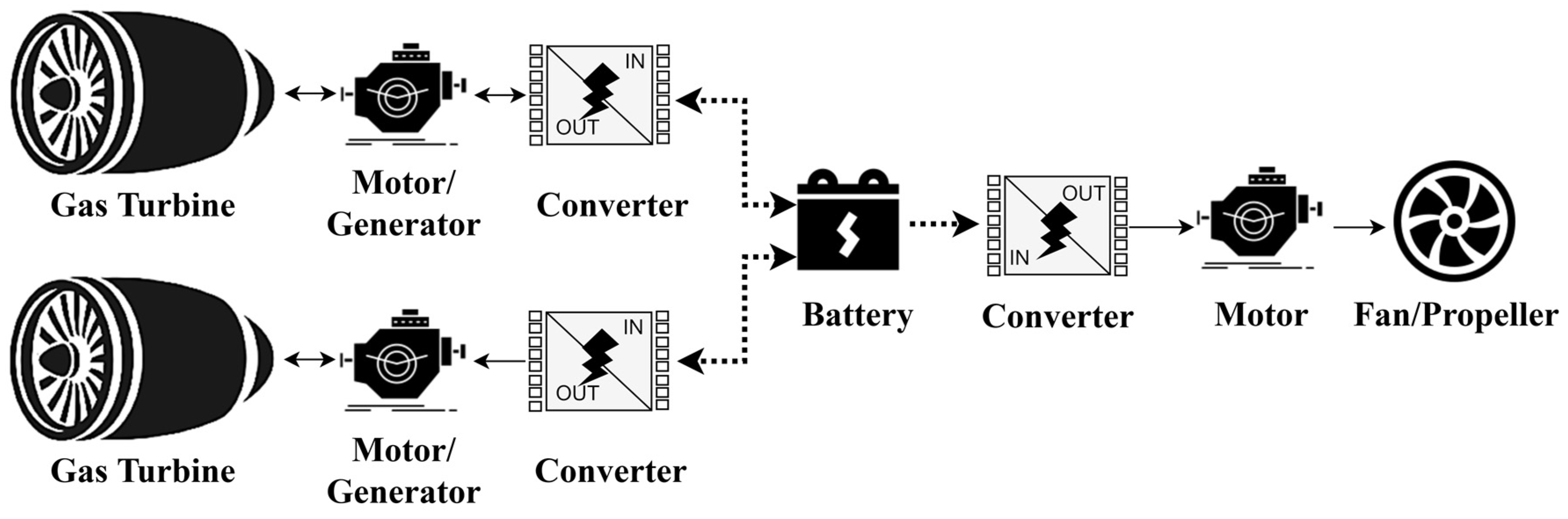
2.3. Parallel Hybrid Electric Architecture

In a parallel hybrid electric architecture, as shown in Figure 3, both the electric motor and the conventional gas turbine are mounted on a shaft to drive the fans/propellers. The electric power on-take can be used to boost either the low-pressure shaft, known as Mechanically Integrated Parallel Hybrid architecture (MIPH), or the high-pressure shaft, known as Cycle-Integrated Parallel Hybrid architecture (CIPH) [34]. Additionally, the electric motor is backed up with a battery energy storage system that can be charged onboard or on the ground.
The parallel configuration requires fewer electrical components compared with the serial hybrid configuration, so it has the advantage of weight saving [35]. However, the operation and control in the parallel electric configuration are relatively complicated due to the mechanical coupling relations of the propulsive device, gas turbine, and electrical system. Furthermore, the parallel hybrid electric operation may deteriorate the performance of the turbomachinery components. For example, in MIPH arrangements, under a fixed thrust demand, hybridization operation reduces the power demand from the engine core, and the gas turbine operation of the overall pressure ratio, pressure build-up, and core/bypass mass flow is noticeably affected due to the components’ rematching effects, as shown in Figure 4 [36]. To provide a lower shaft power, the rotational speed of the high-pressure shaft is accordingly reduced, which causes a flow mismatch between the two spools [37]. This will eventually lead to a reduced surge margin in the low-pressure compressor and significantly increase the fan rotational speed [34]. For CIPH configurations, the low-pressure compressor is more likely to choke because of the components’ rematching caused by hybridization, and the high-pressure shaft compressor moves towards a high rotational speed [34]. Thus, the operation of the parallel hybrid configuration is complicated, because it should avoid potential fluttering (stalling or choking) and ensure mechanical integrity.
The applications of and ongoing research on parallel hybrid electric architecture are summarized in Table 4.
The technology levels of the electrical system components required by parallel hybrid electric architecture are investigated in [10] and presented in Table 5. The potential applications of all-electric and parallel hybrid electric propulsion systems are largely dependent on the technical advances in battery energy storage systems. A regional jet or single-aisle aircraft is feasible with a battery specific energy of over 800 Wh/kg for a parallel architecture. However, the current state-of-the-art battery specific energy is only 200–250 Wh/kg [10].

2.4. Turboelectric Architecture

In the turboelectric configuration as shown in Figure 5, the gas turbine drives the generators to provide electricity. The electricity is subsequently transmitted to power inverters, individual direct current (DC) electric motors, and eventually drives the individual distributed fans/propellors. The turboelectric configuration does not include electrical energy storage; it stores all energy in jet fuel and converts part or all of it to electricity. The key studies on turboelectric research are listed in Table 6.
Turboelectric architecture with distributed propulsion has been identified as the top priority approach for developing advanced electric propulsion technologies that could be implemented in the next c. 10–30 years for aviation decarbonization, because it does not rely on the technical advances of battery energy storage. Furthermore, the performance requirements of the electrical system components can be developed with smaller advances beyond the state-of-the-art technology, as shown in Table 7 [10].

3. Electrified Aircraft Propulsion System Dynamic Modeling and Control System Design

In this section, the challenges and technical barriers of the control system design for advanced electrified aircraft propulsion (EAP) systems are presented. Then, the control methods for integrated power and propulsion systems are introduced with the latest research.
In a conventional gas-turbine aero-engine control architecture, as shown in Figure 6, the electronic engine control (EEC) units calculate the control commands according to the received requests of thrust demands, aircraft power, and bleed offtake demands and the engine-sensed feedback measurements. Then, the control commands are sent to the actuator of the engine-fuel metering valve. Herein, the fuel flow rate is the primary control variable to control the engine thrust output. As the thrust cannot be measured directly, a closed-loop fuel flow controller is normally designed based on a correlated feedback measurement of the fan speed or engine pressure ratio [48]. Furthermore, the actuators of the variable-area fan nozzle (VAFN) and variable bleed valve (VBV) are open-loop scheduled to improve engine operability. The control system design of aircraft propulsion systems is highly challenging and complex due to nonlinearities, performance constraints, and physical and safety limits [49]. The operation of a gas turbine is an extremely complex nonequilibrium and nonlinear aerothermodynamic process, and the model accuracy is expected to capture the interaction accurately enough for control design but without requiring excessive computational efforts [50,51]. Additionally, the aircraft operates in a wide flight envelope over an extreme range of environmental conditions, defined by altitude, Mach number, and temperature [52]. The control system of a gas turbine aero-engine is not only responsible for maintaining thrust at a specified level for a given throttle, guaranteeing a fast and smooth transition operation between demanded thrust levels, but must also take into consideration the safety, reliability, maintainability, and environmental impact [53]. The control design is a highly demanding task necessitating the fulfilment of a set of performance and safety requirements including the steady state accuracy, transient accuracy, disturbance rejection, stability, stall margin, structural integrity, and engine degradation. In summary, aircraft propulsion control systems can be classified as in Table 8. The control system design procedure is normally as follows: the flight envelope is divided into several regions. In each region, the linear model is obtained for the flight conditions, so that the controllers are designed for each linear model using control theories. Finally, the full flight envelope control is achieved via gain scheduling [54].
Future electrified propulsion systems will pose further significant challenges because of new configurations, structures, and electric components, presenting much more complex problems with significantly increased numbers of control system parameters to design and tune [55]. In the EAP control architecture, as shown in Figure 7, the supervisory controller is the communication interface between the aircraft and the propulsion system and is also responsible for coordinating the operation of both subsystems, the conventional gas turbine and the electrical powertrain. The supervisory control strategies are proposed to minimize fuel/energy consumption, lessen the challenges of thermal management, achieve dynamic control to ensure engine operability during transients, and maintain overall operating limits [48]. In the bottom layer, EEC units control the gas turbine’s operation, and the electronic component controller (including the motor control unit, generator control unit, power electronic control unit, and battery management system) regulates the operation of the electrical powertrain.
Apart from the existing technical barriers of conventional gas-turbine aero-engine control, the EAP control system design brings with it more challenges and concerns. Firstly, the coupling and interaction between the gas turbine and electrical powertrain should be considered, which involve mechanical, hydraulic, thermal, electrical, and electronic elements. The interaction can result in a loss of setpoint tracking and safety constraint violations, and the power on-take provided by electric motors could compromise the gas turbine operability [56]. Taking MIPH architecture as an example, the gas turbine operation in terms of the overall pressure ratio, pressure build-up, and core/bypass mass flow is noticeably affected due to the electrical power on-take and component rematching effects. The electrical power on-take will cause a decrease in the resistive torque load on the engine shaft, significantly increase the fan rotational speed, and eventually lead to a reduced surge margin in low-pressure compressors [34]. Another challenge is the negative impedance instability behavior in the power load regulation of the electrical powertrain subsystem, where an increase in voltage across the device’s terminals results in a decrease in the electric current, and vice versa [57]. Along with the low inertia of the electrical powertrain subsystem, the negative impedance instability is very likely to destabilize the voltage buses [58]. Furthermore, the dynamics of a conventional gas turbine subsystem and electrical powertrain subsystem have differences in terms of their time scales; specifically, the voltage dynamics of the electrical powertrain have time constants in the order of milliseconds, while the gas turbine’s shaft rotational speeds have time constants in the order of seconds [59]. This phenomenon further complicates the control system design of the integrated EAP system, and the local controllers of subsystems are designed for different update rates, which limits the opportunities for communication. The frequency band of interest for EAP control systems is presented in Figure 8. Based on the dynamic response gap between the engine and electrical powertrain, the engine response lag can be potentially compensated by the motor torque to reduce the shaft torque fluctuation [60]. In addition, more failures may occur in the EAP system due to the diversity of components and the coupled operation. Thus, fault detection and tolerance, or system reconfiguration in response to faults, are expected to be embedded within the control system design [48].
Table 9 outlines the main control methodologies for aircraft propulsion systems, including both the conventional propulsion system and the electrified aircraft propulsion system. However, the control methodologies for electrified aircraft propulsion systems have not been universally investigated. Each control method will be introduced individually, highlighting the benefits and limitations of its application. Additionally, the distinct differences between classical control theory and modern control theory are presented in Table 10.

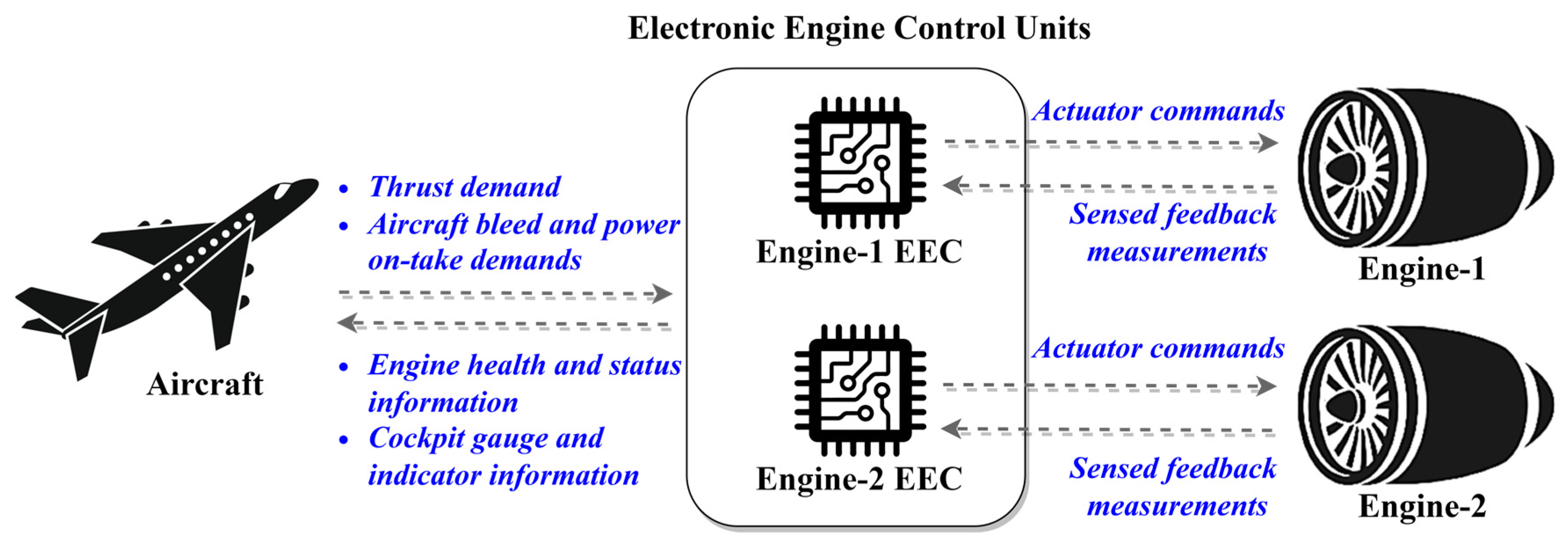
3.1. Classical Control

The most common example of a classical control method is the proportional integral derivative (PID) controller, which is widely used in practice due to its simple implementation and relative efficiency [61]. However, PID controllers can only be used for single-input–single-output (SISO) systems. Thus, the application of a PID controller in a multivariable aircraft propulsion system relies on system dynamics decoupling to produce multiple SISO systems that can be handled directly, but this approach will limit the allowable controller gains for system stability [62]. Another approach is a control structure consisting of a cascaded series of control loops with a supervisory multivariable controller that will coordinate control loops and generate output setpoints as references for low-level actuator PID controllers, which is well-known as a hierarchical control structure [63]. Furthermore, the classical control theory cannot be applied to nonlinear systems directly; thus, the system linearization at predefined equilibrium points is required before controller design. Additionally, min–max limiting logic is a necessity for system safety constraint handling, e.g., maximum speed limits, combustor pressure limits, and ratio unit limits [49].
The basic design process and control architecture of a commercial turbofan engine is presented in [49]; it contains an engine pressure ratio and fan speed setpoint controller and limit regulators to constrain the transient to guarantee safe operation, including a rotor speed limiter, a combustor pressure limiter, an acceleration schedule, and a ratio unit limiter. These are all implemented by the PI controller with integral wind-up protection, and a min–max strategy is applied to determine the control signal sent to the fuel metering valve. Furthermore, the aircraft propulsion system operates over a wide range of flight conditions, which adds significant complexity to the control system design. This challenge is handled by using gain scheduling with interpolation, to break a large, complex, nonlinear system into a series of range-limited linear subsystems and tune the controller at each breakpoint. At each time step, the controller gains are obtained by linear interpolation between the nearest defined subsystems [52]. On this basis, meta-heuristic global optimization algorithms, namely the competent genetic algorithm, linkage-learning genetic algorithm, and aggregative gradient-based algorithm, have been respectively applied to solve the engine controller gain-tuning problem for a turbojet gas turbine, with the global optimization objectives of response time, fuel consumption, maneuverability, and safety considerations [55,64]. Additionally, a cascade ensemble radial basis function (RBF)-based optimization algorithm is also proposed for global optimal control gain scheduling for aero-engine transient processes [65]. Fuzzy gain scheduling is proposed for the PID controller tuning, which is achieved by using nonlinear Mamdani mapping. Additionally, the multiobjective genetic algorithm is employed to find the optimal solutions for a wide-envelope controller covering idle, cruise, and full-power conditions [53]. For system safety constraint handling, the min–max limit protection is improved by using the state feedback method and linear matrix inequalities, which can significantly reduce the probability of transient limit violation [66]. However, due to the vacillating nature of the min–max structure, the stability of the overall system cannot be guaranteed. Thus, a main–max selector scheme with a stability analysis method is further developed by transforming the basic control structure into the form of Lure’s system, where the global asymptotic stability is proved for the control system of a turbofan engine [67]. A novel model-based multivariable limit protection control method is proposed to improve the loss of thrust and is achieved by adaptive command reconstruction, multiple control loop selections, and switch logic [68]. In [69], nonlinear dynamic models of turbomachinery and electrical power systems were developed for the STARC-ABL concept with a partially turboelectric single-aisle propulsion system. A gain-scheduled PI controller with protection logic for turbomachinery and a PI speed controller with a vector controller of pulse width modulation (PWM) was developed based on the piece-wise linear model, and the controller design was examined for the performance metrics of increasing time and operability margins. An optimal control and energy management method for hybrid gas–electric propulsion has been developed, wherein the standard PI controller is adopted to command fuel flow for turbofan speed regulation, and the electromechanical torque is given by linear state feedback and bias, with gains calculated numerically from engine linearization [70].

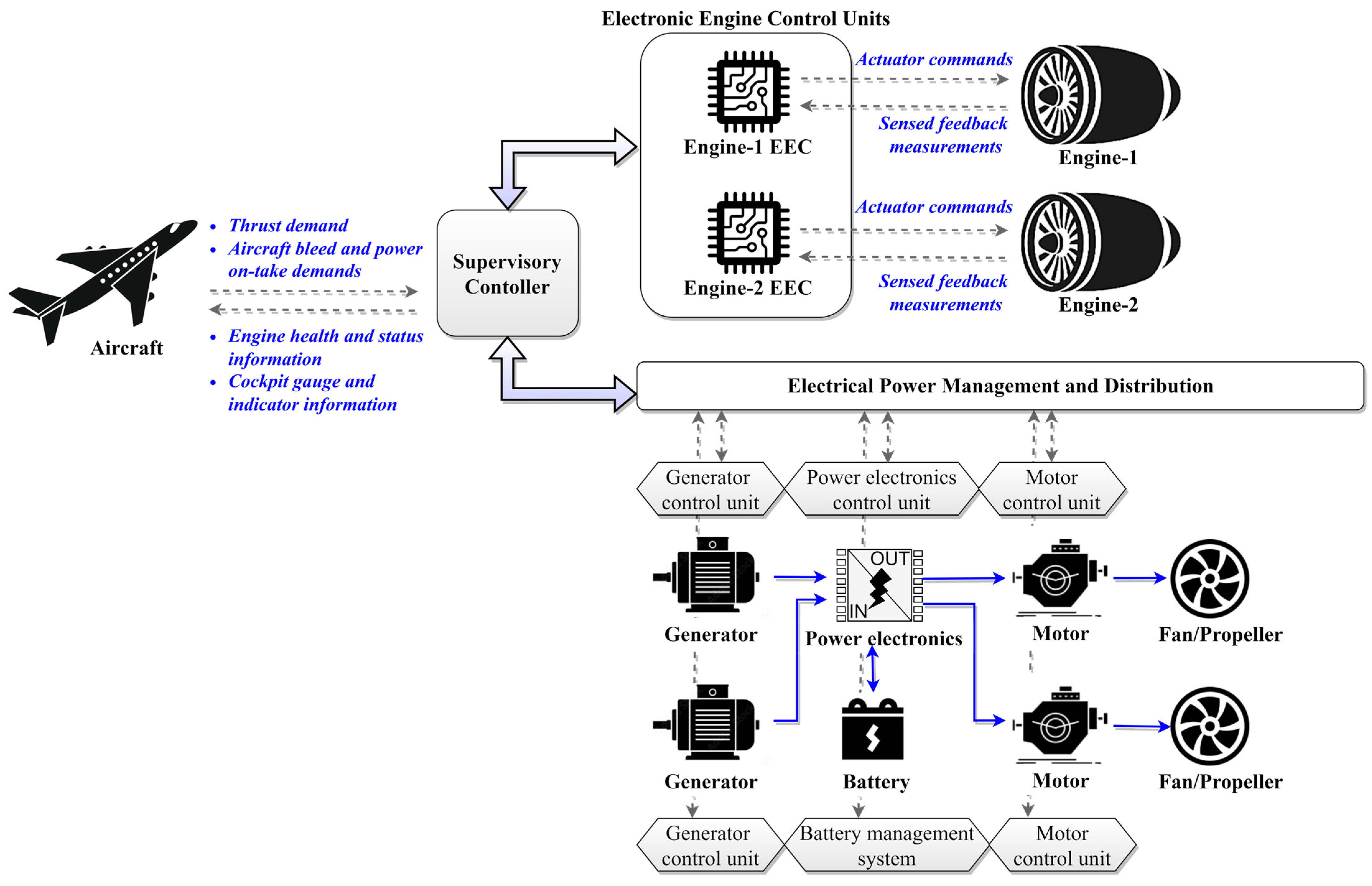
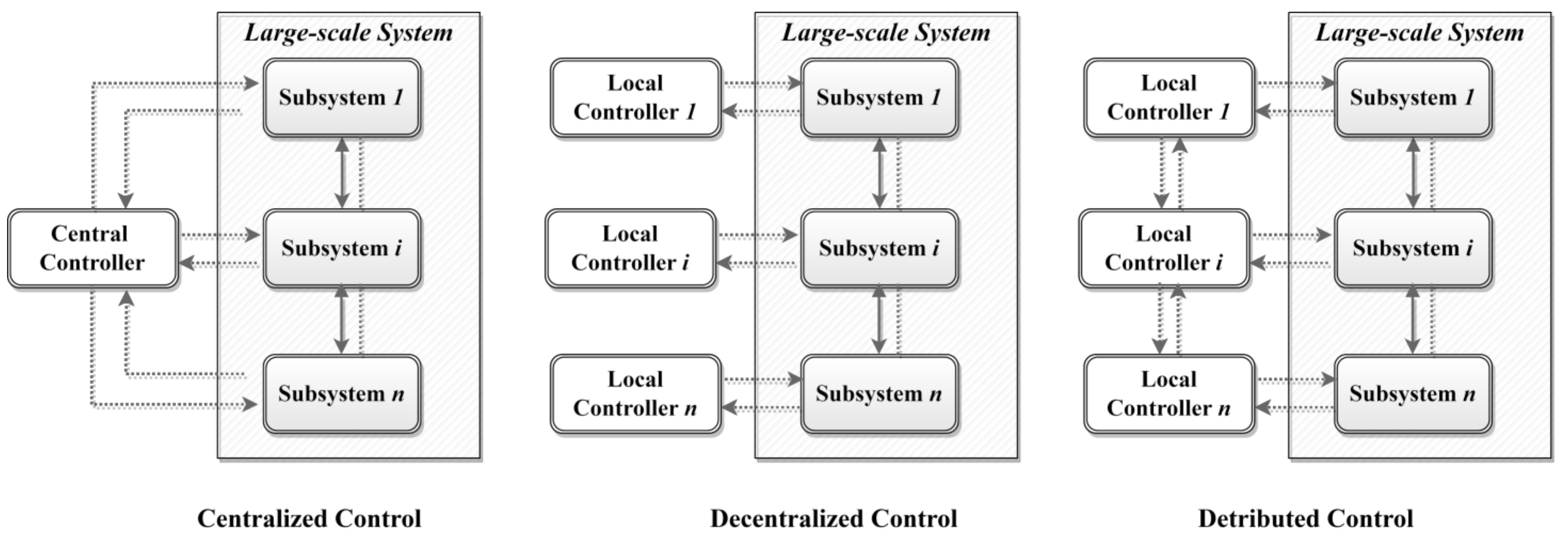
3.2. Hierarchical Control

Hierarchical control is a form of the networked control system, which is widely used for multienergy systems; the main idea is to decompose a complicated control problem into different time-based modules and in turn organize it into layers. This system can be designed in centralized, decentralized, distributed, or hybrid configurations, as shown in Figure 9 [71]. The centralized control model can provide the optimal solution because it has full knowledge of the system and authority over all inputs; however, it is computationally demanding and does not consider the preservation of subsystem privacy. In decentralized control, both subsystems are operated separately by local controllers without communication. This introduces less computational burden than the centralized control strategy. The interactions among subsystems are largely treated as exogenous disturbances to be rejected by subsystem local controllers. Without a consideration of subsystem interactions, the control performance will be degraded. The distributed control can achieve coordinated control actions where local subsystem cost functions are augmented with a global term to account for the impact of their inputs on the entire system [72].
The hierarchical control scheme is normally implemented with a combination of other control methods, such as classical PI–hierarchical control, hierarchical multiagent control, and hierarchical predictive control. For instance, a two-layer hierarchical architecture is proposed to coordinate the operations of a twin-engine propulsion system, where the upper-propulsion-level controller accounts for load balancing and health management, and each individual engine is operated under the supervision of a local discrete-event supervisory controller at the lower level [74]. Furthermore, a hierarchical multivariable robust control design with nonparallel distributed compensators is proposed for conventional turbofan engines, with the model representation of an uncertain TS fuzzy model, where the level-one compensator ensures the robust performance, and the level-two compensator restrains the uncertainty [75]. Furthermore, a hierarchical model predictive control (MPC) approach is proposed for aircraft electrothermal systems, wherein the coordination of electrothermal systems is achieved by decomposing the multi-energy-domain constrained optimization problem into a set of computationally efficient subproblems that can be solved in real time [76]. For hybrid electric aircraft, a set-based hierarchical MPC framework has been proposed and proven to be a computationally efficient approach to coordinate complex systems across multiple timescales whilst providing guaranteed constraint satisfaction [77]. To face the notable challenge of the coordination of multidomain and multi-timescale system dynamics, a hierarchical control architecture with a predictive controller and graph-based modeling framework has been proposed; the upper-level MPC controller with a long preview horizon is designed to plan the slow timescale system dynamics of battery SOC, the lower-level MPC controller is used to regulate the medium timescale system dynamics of the propeller speed and genset current, and the regulatory embedded controller controls the fastest timescale system dynamics of motor speed and avionic load current directly [78]. A three-level hierarchical load management system has been proposed for other electric aircraft; the upper task level is designed for electrical consumption demand allocation, the medium level is for optimal power distribution, and the lower level is for condition monitoring [79].

3.3. Robust Control

Robust control is an approach to controller design that explicitly deals with bounded system uncertainty and disturbances [80]. The most important techniques of robust control are H-infinity control and sliding mode control, which have been extensively used for aero-engine controller design.
For H-infinity control theory, a novel robust gain-scheduling tracking control strategy for aero-engines has been proposed that considers performance degradation. In this study, the onboard engine model with health parameters is represented as piecewise linearized Kalman filters. Then, H-infinity control theory is used for controller design to achieve good reference tracking with robustness and stability [81]. The H-infinity output tracking problem for aero-engines with a model representation of switched linear-parameter-varying (LPV) systems is also investigated. In [82], a set of switched LPV controllers and a parameter- and mode-dependent switching law are developed to enhance control design flexibility based on multiple-parameter-dependent Lyapunov functions. In [83], the switched LPV model is converted to a switched convex polytopic form with hysteresis switching logic, and then a theoretical sufficiency criterion is provided to guarantee H-infinity performance. Furthermore, a parameter-dependent multiple discontinuous Lyapunov function approach is proposed to solve the H-infinity refined antidisturbance control problem for the switched LPV systems, achieving the required disturbance attenuation and rejection [84]. H-infinity control theory has not been investigated for electrified aircraft propulsion systems to date, but there exist some studies of H-infinity control method applications in hybrid electric vehicle powertrains. In [85], a hierarchical control structure with two robust H-infinity controllers is proposed for plug-in hybrid electric vehicles to achieve a fast and smooth operating mode transition, where the upper-layer H-infinity controller is responsible for calculating the demand clutch torque considering the clutch engaging time and the vehicle jerk, and the lower-layer H-infinity controller aims to perform accurate position tracking control even with the parameter uncertainties and external disturbance. The cooperative control of the drive motor and clutch for the gear shaft is effectively solved by H-infinity loop shaping, even in the presence of model uncertainties and disturbances, as well as the coupling effects between subsystems [86].
Sliding mode control (SMC) is recognized as an efficient approach to robust controller design for complex high-order nonlinear dynamic systems under uncertain conditions. It has the benefits of low sensitivity to system parameter variations and disturbances. Furthermore, SMC can decouple the overall system motion into independent partial subsystems of a lower dimension and consequently reduce the complexity of controller design [87]. In [88], a multi-input and multi-output control scheme is proposed for aero-engine setpoint tracking; it consists of a multivariable SMC controller as a nominal regulator, a series of single-input SMC regulators with min–max selection logic to protect limits, and predictor-based switching logic to ensure the smooth transitions between the main regulator and the limiters. Furthermore, an improved multipower reaching law is proposed for SMC controller design to reduce high-frequency oscillation in aero-engine tracking control [89]. SMC has also been investigated in hybrid electric vehicle powertrain control. For instance, a double-SMC-based control system design is proposed for the efficiency improvement of series hybrid electric vehicles, which also has the advantages of modularity and can be easily implemented on other series hybrid electric vehicle powertrain systems with model and parameter uncertainties [90]. In [91], a fuzzy SMC control method is proposed for the fast and smooth mode transition of parallel hybrid electric vehicles, also offering robustness against vehicle model uncertainties.

3.4. Optimal Control

Optimal control is an approach to determine the control signals of a dynamic system to satisfy the physical constraints whilst minimizing the cost function [92]. The optimal control problem is normally formulated as the cost function mapping of system states and control actions, states and input constraints, and system dynamics, which is represented as a set of differential equations with initial conditions [61]. The representative optimal control methods include the linear quadratic regulator (LQR) and the linear quadratic Gaussian (LQG) methods. In LQR control theory, the system dynamics is represented in a linear time-invariant form with the quadrative objective function, and the analytically derived feedback control law is given by using a mathematical optimization algorithm [63]. An LQR-based controller has been developed to stabilize systems and provide better performance in terms of settling time, rising time, and maximum overshoot than a classical PI controller [93]. Additionally, a nonlinear controller was designed using the feedback linearization technique in conjunction with pole placement and LQR theory to guarantee accurate command tracking and mode blending and ensure the robustness of the engine controller to parameter variations [94]. Furthermore, direct surge margin control for aero-engines has been proposed based on an improved support vector regression (SVR) machine and LQR theory, wherein the SVR machine is used to construct a surge margin prediction model and the LQR controller is improved by augmenting the tracking errors into the state vector to guarantee good robustness and performance over a wide range of power states and flight conditions [95]. For the applications in electrified propulsion systems, an LQR controller has been developed for hybrid electric urban air mobility; this controller can effectively achieve the desired steady state for a wide range of initial conditions [96]. The LQG method has been further developed based on LQR control theory, with a state estimator providing an estimated state vector of measurable outputs [63]. A robust controller for gas turbines has been proposed based on the discrete-time LQG/loop transfer recovery (LTR) approach with self-tuning features, which provides a measure of robustness with regard to both structured uncertainty and the uncertainty caused by the engine operating environment [97]. On this basis, an online estimation method for gas turbine rotation has been further developed based on the LQG/LTR method, which can have only a small effect on the system’s natural frequency but allow for a larger open-loop gain to improve the steady state tracking control accuracy [98]. However, this method has not yet been rigorously investigated for applications in electrified aircraft propulsion systems or hybrid electric vehicle powertrains.

3.5. Model Predictive Control

Model predictive control (MPC), also known as receding-horizon control, determines the current timeslot control action by solving a finite-horizon optimization problem over the prediction horizon. Then, the prediction horizon is shifted forward, and the optimization calculations are repeated with updated plant states [99]. The MPC method offers advantages when dealing with nonlinearities and handling constraints. However, the closed-loop stability of the MPC control system cannot be guaranteed, and it is inherently less robust than classical feedback, where the optimizations are infeasible with large uncertainties [63,100]. MPC has been extensively applied in the control system design of both conventional propulsion systems and electrified propulsion systems. For example, a multivariable MPC controller was designed and implemented in real time based on a discrete-time linearized state-space model to provide the required thrust and protection limits, where a feedback correction was used to compensate for the model mismatch [101]. In this framework, a semi-alternative-optimization-strategy-based MPC controller was proposed based on the extended Kalman filter turbofan engine model [102]. An advanced constraints management strategy for real-time gas turbine transient control was developed based on the MPC approach. In this study, the MPC controller was designed to identify the engine control modes, which was achieved by using Lagrangian multipliers to handle the constraint inequalities and Hildreth’s quadratic programming to select the controller weighting values [103]. To improve the engine response performance and reduce the computational complexity, direct thrust control with nonlinear MPC was proposed based on a linearized online sliding-window deep neural network predictor [104]. For application in EAP systems, a coordinated MPC controller has been developed to achieve the setpoint tracking of large transient thrust and electrical loads whilst ensuring system constraints [56,105]. This study was further developed to improve the match between the rate-based linear prediction model and the nonlinear system by introducing an auxiliary offset state [106]. Furthermore, the bus voltage behaviors were stabilized by imposing a power rate constraint and incorporating this with the energy storage subsystem [107]. Furthermore, a distributed MPC controller was designed based on the alternating direction method of the multiplier. This work presented an innovative approach accounting for the differing control update rates of gas turbine and electrical powertrain subsystem local controllers and the preservation of subsystem privacy [108].

4. Electrified Aircraft Propulsion System Supervisory Energy Management Strategy

Energy management strategies (EMSs) have been extensively explored for hybrid electric vehicles, microgrids, and power grids [108,109]. However, HEA EMS consideration is recognizably different from these ground-based energy systems. Especially for commercial aviation, the mission analysis and performance assessment are based on the premise of balancing the thrust to drag with the fuel flow and electrical power flow within the set operational and performance constraints defined by the top-level requirements. Normally, the mission segments are discretized by an energy-based approach with a mission explicitly defined for each step, which involves a large number of iterations between the propulsion system performance module and the aircraft performance module based on a multidisciplinary analysis of the aerodynamics, propulsion system performance, and weight property [110]. Moreover, the weight is a major consideration for flight mission analysis, especially for hybrid electric aircraft, since the additional weight of the electrical powertrain and battery energy storage will degrade the integrated aircraft performance due to the induced weight-related drag penalty [111]. Propulsion system electrification and hybridization can ultimately improve block fuel burn and emissions at the isolated propulsion system level due to electrical power on-take and more efficient operation, but the promising improvements and benefits cannot be guaranteed from the perspective of the integrated aircraft level, due to the weight-related drag penalty [36]. Furthermore, the in-flight gas turbine fuel flow also leads to changes in aircraft mass and further affects the aerodynamics performance, such as lift-dependent drag and thrust demand, especially for regional jets that operate at a high altitude with long flight durations. Therefore, a fully coupled propulsion–aerodynamic model with multidisciplinary analysis is required for hybrid electric propulsion system performance assessment at the integrated aircraft level. Furthermore, energy onboard should be equal to mission energy demand as a key system constraint, since the carrying of an excessive amount of energy induces a weight and drag penalty [112]. For hybrid electric aircraft with dual energy sources, both the consumable mass energy sources of the fuel and the nonconsumable mass energy sources of the battery should be considered. Thus, hybrid electric aircraft EMSs should be considered from a global optimization perspective at the integrated aircraft level with a fully coupled aerodynamics–propulsion multidisciplinary model, which will also greatly increase the system complexity and computational load. Thus, the HEA EMS is complicated, challenging to implement, and has not yet been widely investigated.
This section provides a comprehensive survey of the HEA EMS literature to date, systematically summarizes the state-of-the-art HEA EMS technology, and explores the research trends in this field. EMSs can be classified as rule-based and model-based optimization methods. Model-based optimization strategies can be further divided into global optimization EMSs and instantaneous optimization EMSs, as shown in Table 11.

4.1. Rule-Based EMS

The rule-based EMS is an effective approach for real-time implementation; it relies on a set of predefined rules to take control actions instead of involving explicit minimization or optimization [113]. The design of rules is generally based on heuristics, designers’ expertise, or the insights of global optimal solutions through the offline optimization process. Thus, the rule-based EMS is practical to implement and has a low computational load, but the HEA performance is highly dependent on the designers’ expertise and sensitive to the flight mission profile.
A modeling approach for the rule-based EMS was investigated for the AirTaxi mission of hybrid electric rotorcraft to reduce fuel consumption. It proposed and compared four modes with the consideration of battery aging effects: only thermal engine operation, only electric machine (EM) operation as a motor, both engine and EM operation with battery discharging, and both engine and EM operation with battery recharging [114]. In [115], a rule-based controller is designed to manage the power flow of the parallel HEPS with three operating modes: internal combustion engine (ICE) only, ICE and EM, and ICE and GE. By the utilization of both electric machines and internal combustion engines, HEPS can effectively achieve fuel saving and a reduction in take-off noise and emission levels. The systematic hybrid aircraft power schedule optimizer (SHAPSO) is proposed in [116]. Additionally, a rule-based EMS is presented to determine the optimal power management of a parallel HEPS with the goals of mission block fuel burn reduction over the flight envelope. The rule-based power schedules of constant power, power at climb, and power at cruise are proposed and compared with the optimal control method and dynamic programming. A fuzzy state machine (FSM)-based EMS has been proposed to control the power flow for a hybrid electric UAV for online application [117]. It innovatively couples fuzzy logic with a state machine, which can satisfy the power demand and effectively achieve block fuel reduction for real-time implementation. A fuzzy logic parameter updating (FLPU) method was developed to achieve adaptive power distribution for a light electric aircraft with the dual energy sources of battery energy storage and fuel cells. The proposed method could adaptively update the power distribution algorithm based on the aircraft operation conditions [118].

4.2. Convex Programming

Convex programming (CP) is widely used to solve optimal control problems in aerospace engineering for onboard real-time applications because of its fast convergence and global optima [119]. A general convex optimization problem can be described as Equation (1):
Minimize   f 0 x
subject   to   f i x b i ,   i = 1 , , m ,
where the functions f 0 , , f m : R n R are convex, i.e., satisfy
f i α x + β y α f i x + β f i y
for all x , y R n and all α , β R with α + β = 1 ,   α 0 , β 0 .
The algorithms are only applicable when the problem is strictly formulated in convex terms: (1) the objective function must be convex, (2) the inequality constraint functions must be convex, and (3) the equality constraint functions must be affine [120]. Thus, the EMS using convex optimization requires strong model simplifications to transform a nonconvex problem into a convex problem. For instance, HEA optimal energy management is formulated as a convex problem to minimize the fuel consumed over a planned flight path, where the point-mass aircraft dynamic model, the electrical powertrain, and the gas turbine are simplified using quadratic approximations. Furthermore, this study requires the drive power to be approximated a priori by assuming constant aircraft mass for the duration of the flight [121]. A convex multiobjective optimization method is proposed for a hybrid electric aircraft to minimize fuel consumption and polluted emissions during the entire flight mission. The optimal EMS problem is formulated as mixed-integer nonlinear programming by replacing the logic constraints of battery energy storage system operation with the Karush–Kuhn–Tucker optimality condition [122]. A real-time supervisory energy management control method is proposed for HEA series and parallel propulsion systems. The convex formulation is derived from four simplifications: (1) a prior flight mission profile and power demand; (2) convex propulsion system loss map functions based on an assumption of the monotonicity of the loss map; (3) reformulating the point-mass aircraft dynamics as a quadratic function; and (4) relaxing the power balance equality to the inequality. This convex optimization problem is solved by the alternating direction method of multipliers (ADMM) algorithm, which can reduce the computation time by orders of magnitude compared with the general convex interior point solver, CVX [123]. In summary, the challenge of using convex optimization lies in recognizing and formulating the convex optimization problems. Once a problem is formulated as a convex optimization problem, it can be solved efficiently using algorithms, e.g., the gradient descent method, the steepest descent method for unconstrained minimization problems, Newton’s method for equality-constrained minimization problems, and interior-point methods for inequality-constrained minimization problems [120].

4.3. Dynamic Programming

Dynamic programming (DP) is a model-based numerical optimization method based on Bellman’s principle of optimality. The DP algorithm is widely used in energy management strategy problems to provide the global optimal solution [124]. In the DP algorithm, the problem is gridded according to time, states, and control signals and then divided into a sequence of subproblems which are solved recursively backward in time from the final step to the first. The optimal solution is achieved by minimizing the cost function, which is defined as Equation (3) [108]:
J = k = 0 N 1 g k x k , u k , w k + g N x N
where   g N represents the terminal cost; g k is the cost function incurred at the time slot k; and x k , u k , w k denote system states, control decision, and disturbances, respectively, at the time slot k.
The cost function of each DP subproblem is defined as Equation (4):
J k x k = m i n u k U k x k g k x k , u k , w k stage   cost + J k + 1 f k x k , u k , w k cost - to - go
where k = N 1 , N 2 , , 0 and the optimal solution is calculated backwards from N-1 to 0 with the initialization of terminal cost J N = g N x N . The DP algorithm requires the decomposition of the problem into subproblems, so the optimal solution accuracy highly depends on the resolutions of the problem discretization. Additionally, the computational demand will exponentially increase with the number of gridded variables, which is called “the curse of dimensionality” [125].
The application of the DP algorithm in hybrid electric aircraft was first investigated to optimize the power management and torque split of the powertrain for a parallel hybrid electric UAV considering terminal state constraints. The study proposed a quasi-real-time iterative algorithm based on the DP algorithm and further explored new flight capabilities by the utilization of hybrid powertrain architecture [126]. A DP-algorithm-based EMS was proposed to find an optimal power-splitting sequence to minimize the fuel consumption over the whole flight mission for a hybrid electric lightweight rotorcraft. The optimal EMS control problem was modeled as a graph structure, where the splitting sequences were represented as the paths with the transition cost weights. Based on the graph structure model, the optimal splitting sequence (shortest energy path) was obtained by using the Dijkstra algorithm [127]. Furthermore, an offline EMS optimization method was proposed using DP to minimize the fuel consumption in a hybrid electric helicopter for urban air-mobility considering the effect of battery aging. This study assumed a planned flight mission profile and considered a constant take-off weight, with the saved fuel being converted into payload [128]. Similarly, an optimal energy management methodology was proposed to minimize fuel consumption based on the DP algorithm with a prescribed flight mission; a point of originality was that this study took into account energy recovery via a propeller during descent [129]. However, these studies assumed a fixed required propulsive power demand as prior knowledge, failing to consider the propulsion–aerodynamic coupling effects and neglecting the variation in aircraft weight during flight. In summary, the DP algorithm can provide the optimal global solution, but it is not applicable for real-time implementation because it requires a priori information and a backward discretized model [125]. Therefore, the DP algorithm is normally used to design rules for rule-based EMSs or as a benchmark to evaluate other EMS solutions.

4.4. Pontryagin’s Minimum Principle

Pontryagin’s minimum principle (PMP) is a model-based analytical optimization method that can provide a globally optimal solution by transforming a global optimization problem described by DP into an instantaneous Hamiltonian optimization problem and then minimizing the Hamiltonian function according to the co-state [130]. This method has been widely used in the EMS problem of hybrid electric vehicles [131,132,133]; however, few studies have investigated PMP method application in the field of HEA EMS problems. This is because analytical solutions are frequently not applicable for complicated problems with complex constraints [134].
The Hamiltonian function is defined as Equation (5) [113]:
H x t , u t , λ t , t = L x t , u t , t + λ ( t ) T f x t , u t , t
where f x t , u t , t is the system dynamics model; L x t , u t , t is the instantaneous cost; and λ t is a vector of the optimization variables—co-states of the system. In PMP, the following conditions should be satisfied if x * t is the optimal control law.
  • The state and co-state should satisfy the following conditions, as represented by Equations (6)–(9):
    x ˙ * t = H λ u * t = f x * t , u * t , t
                                                                        λ ˙ * t = H x u * t = h x * t , u * t , λ * t , t
    = L x x * t , u * t , t λ * t f x x * t , u * t , t T
    x * t 0 = x 0
    x * t f = x target
  • For all t t 0 , t f , u * t globally minimizes the Hamiltonian function:
    H u t , x * t , λ * t , t   H u * t , x * t , λ * t , t ,   u t U t ,   t t 0 , t f
    i . e . ,   u * t = arg m i n u t U t H u t , x t , λ t , t
    where U t is the set of admissible control values at time t . This optimal control problem using the minimum principle is normally solved by the shooting method. This method applies an arbitrary initial value of the co-state at the beginning, λ 0 , and then solves the minimization problem for the dynamic model at each time slot. The optimization procedure ends, and the optimal solutions can be obtained if the final values of the state and co-state can satisfy the terminal constraints. Otherwise, the initial value of λ   should be changed until the solution meets all the constraints.
In the research field of HEA EMSs, a PMP-based real-time EMS has been innovatively proposed for hybrid electric aircraft propulsion systems to achieve emission reductions and system efficiency improvements. By applying PMP, the EMS optimal control problem with constraints is converted into a point-wise optimization with the battery pack temperature and SOC as co-states to achieve a computationally efficient solution. Additionally, the formulation of the EMS optimal control problem using PMP strongly depends on model simplification, e.g., assuming a priori knowledge of mission profile data and thrust request [135].

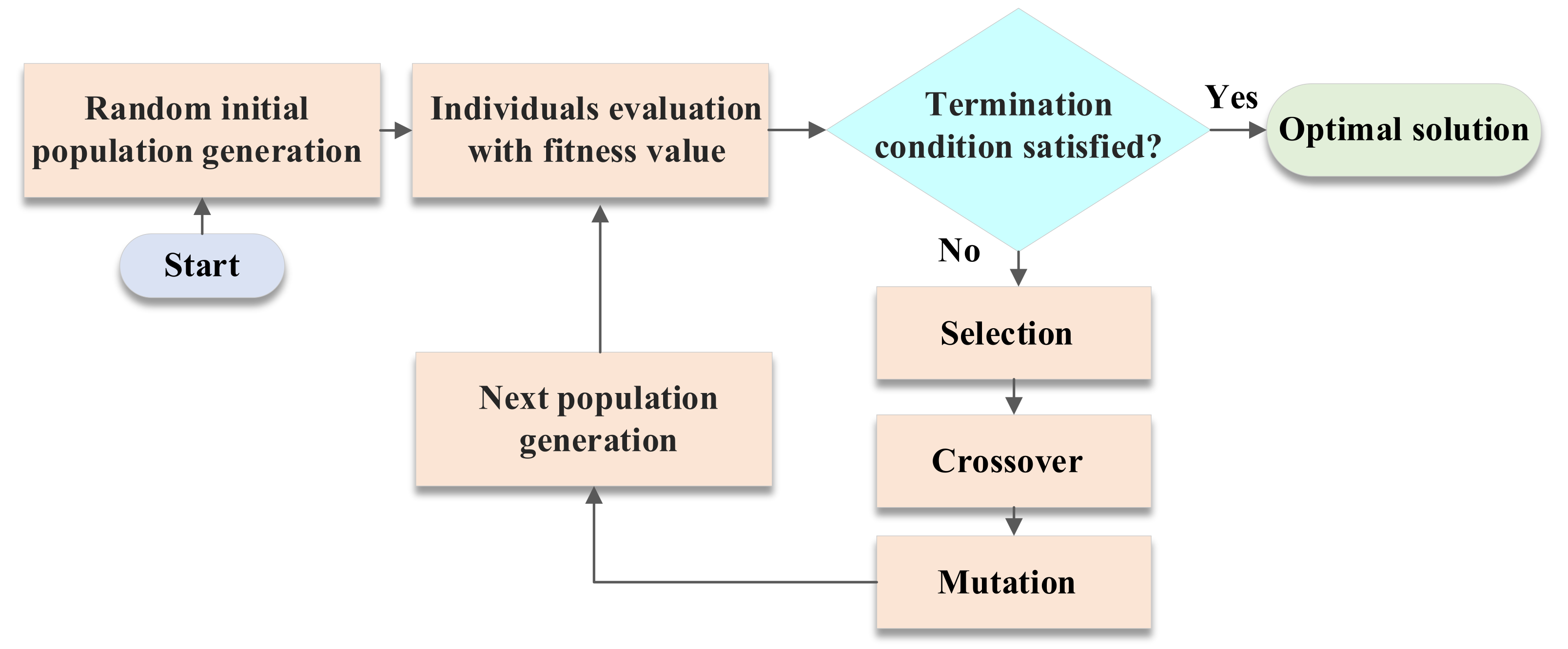
4.5. Metaheuristic Algorithms

Metaheuristic algorithms are derivative-free methods inspired by nature, which are generally utilized to solve optimization problems with a large search space of likely solutions, e.g., simulated annealing (SA), genetic algorithm (GA), differential evolution algorithm (DEA), ant colony optimization (ACO), particle swarm optimization (PSO), and cuckoo search (CS) [108]. These metaheuristic algorithms employ alternative methods to populate candidates for an optimal solution instead of derivative calculations, and the optimization performance and convergence behavior highly depend on the selection of hyperparameters to avoid local minima. These methods have been extensively investigated in offline HEA EMS optimal control problems.
A representative nature-inspired method, the PSO algorithm is inspired by social organism movements in groups, such as swarms and ant colonies. This algorithm populates the states, positions, and velocities of the particles. These particles can interact locally with each other to share information and then store their best positions and the group’s best solution to improve the next population until the target is achieved [136]. The PSO algorithm can be expressed as Equations (11) and (12) [137]:
v d i k + 1 = w v d i k + c 1 · r 1 · p B e s t i k x d i k + c 2 · r 2 · g B e s t i k x d i k
x d i k + 1 = x d i k + v d i k + 1
where i represents each particle; p B e s t and g B e s t are particle best position and global best position; and w ,   c 1 ,   c 2 , r 1 , r 2 are inertia weight, positive parameters, and random parameters within [0,1], respectively. Maximum and minimum particle velocity should be within ± v d max . The PSO algorithm can be effectively applied in the optimization problem with complex objective functions, where only two variables (particle position and velocity) are required in population and iteration.
Another typical metaheuristic optimization method is the GA, which is inspired by natural evolution with the procedures of reproduction, crossover, and mutation and involves randomness to guarantee population diversity [138]. As shown in Figure 10, the algorithm creates a population of individual solutions (chromosome) and randomly selects individuals from the current population as parents to produce the children for the next generation at each generation. Over successive generations, the population converges to an optimal solution where a balance of computational load and precision is achieved [139]. Following the general outline of the GA, the nondominated sorting genetic algorithm II (NSGA II) has been developed to solve a Pareto-optimal front for the constrained multiobjective optimization problem [140].
Metaheuristic algorithms have been extensively used in energy management for electric aircraft. A comparative analysis of the most efficient up-to-date metaheuristic algorithms, such as the artificial bee colony (ABC), grey wolf optimization (GWO), the cuckoo search (CS), and the moth swarm algorithm (MSA), has been presented in the literature [141]. It evaluates the performance of metaheuristic algorithms in the application of energy management for fuel-cell-based hybrid emergency power units in electrical aircraft. In another study [142], the synergy effects between powertrain, structure, and mission are exploited by applying the multiobjective optimization method, NSGA-II, and the S-metric selection evolutionary multiobjective algorithm (SMS-EMOA), and the potential benefit of structural integration and multifunctionalization are addressed. The nonlinear nature of the HEPS for aircraft is highlighted in [143], and DEA techniques are applied for power management in series-, full-electric-, and turboelectric-powered UAVs, respectively. An active energy management strategy is proposed for a fuel-cell/battery/supercapacitor-powered aircraft to control the battery and supercapacitor SOCs as well as to minimize hydrogen consumption by applying metaheuristic algorithms including the ant lion optimizer (ALO), moth–flame optimization (MFO), the dragonfly algorithm (DA), the sine cosine algorithm (SCA), the multi-verse optimizer (MVO), particle swarm optimization (PSO), and the whale optimization algorithm (WOA) [144]. Rendón et al., in [145], proposed a model-based fully coupled propulsion–aerodynamics optimization framework for the HEA EMS problem by using the NSGA-II algorithm to address the design trade-off, i.e., block fuel burn, energy consumption, and emissions. This study showcased an innovative approach considering the sizing cascading effects in HEA propulsion system design and mission analysis.

4.6. Equivalent Consumption Minimization Strategy

The equivalent consumption minimization strategy (ECMS) is a heuristic method to provide effective solutions for optimal control problems. The ECMS algorithm introduces an electricity-to-fuel equivalent factor, which converts electricity consumption into fuel consumption to allow for unifying fuel and electricity consumption in a single objective. The instantaneous equivalent fuel consumption is minimized to obtain instantaneous optimal power distribution, which is defined as Equations (13) and (14), see [113,146]:
W feq ˙ t = W f ˙ t + Q t · P B a t t t L H V
Global :   min P B a t t t U B a t t   t 0 t f W f ˙ t d t ,       S O C min < S O C < S O C max
Instantaneous : t 0 t f min P B a t t t U B a t t W feq ˙ t d t ,       S O C min < S O C < S O C max
where W ˙ f t ,   Q t ,   P B a t t t ,   W feq ˙ t , L H V , and t are actual fuel flow rate, electricity-to-fuel equivalent factor, battery power, equivalent fuel consumption, fuel lower heating value, and time step, respectively.
Using the ECMS method, the global optimization problem is converted to a local instantaneous optimal problem. Due to this, the ECMS algorithm is a more computationally efficient and easier-to-implement method that is suitable for online applications. It can provide control actions close to globally optimal solutions with the tuning of the electricity-to-fuel equivalent factor. The optimal equivalent factor is obtained by offline optimization; thus, the aircraft performance of the ECMS is highly sensitive to the flight mission profile.
A fuzzy-logic-based equivalent consumption optimization method has been proposed for hybrid-electric-powered unmanned aerial vehicles (UAVs) [147], which achieves the suboptimal hybridization of fuel and electrical energy for online optimization and sustains the battery SOC within the desirable range. Furthermore, the authors of [36] developed an ECMS with hard constraints and an ECMS with a penalty function and compared them with a global optimization (GA)-based EMS. With the offline tuning of the equivalent factor, ECMS methods can effectively obtain similar optimal solutions to global optimization (GA)-based EMS methods but significantly reduce the computational time. In [128], an online optimizer was developed based on the knowledge of global optimal solutions provided by dynamic programming, which took particular account of the desired SOC and the actual state of health (SOH) and could be opportunely adapted to specific cases.

4.7. Model Predictive Control

Model predictive control (MPC) has been utilized in an online EMS optimization algorithm to obtain the optimal control actions, where future information is incorporated into the control problem to improve EMS performance [36]. At each sampling time, the algorithm uses the system model to predict the future states of the plant over the prediction horizon with length N, and then the optimal control policy from t to t+N is obtained by rolling optimization. After that, the control policy of the current sampling time is applied regardless of the rest, and the system state is updated accordingly. The MPC-based EMS performance is determined by model fidelity, sampling step, and the length of the prediction horizon [1]. The length of the prediction horizon is tuned accordingly to consider the trade-off between the computational effort and optimization performance. This allows the current timeslot to be optimized while keeping future timeslots in mind. Thus, the MPC EMS can significantly reduce the computational effort as compared to the global optimization algorithm while achieving very similar optimization performance [36].
A nonlinear MPC-based EMS was proposed for parallel HEPS to minimize mission block fuel burn, energy consumption, and emissions, based on a fully coupled aerodynamics–propulsion HEA model. Additionally, the penalty function was introduced to reduce the computational effort but effectively maintain the system constraints [36]. Furthermore, a system-level centralized optimal load and energy management strategy was proposed for aircraft microgrids to schedule the battery system, provide flexibility in the demand side, and satisfy time-varying operational requirements. This was achieved by using a multiobjective MPC model with a mixed-integer linear programming algorithm (MILP) [147]. A predictive control strategy was proposed for real-time implementation that took into account the variation in aircraft mass during flight. At each sampling interval, rolling optimization was achieved by a convex formulation of the problem of minimizing fuel consumption over a predicted future flight path [121,148].

5. Summary

Electrified aircraft propulsion technologies, forming a very promising approach to sustainable aviation decarbonization, were investigated and explored. In particular, this paper provided comprehensive insights into the recent progress in control system design and energy management aspects for electrical aircraft propulsion systems, together with a detailed analysis of the emerging challenges and technical barriers in this new and challenging research field. The control design of aircraft propulsion is a rather demanding task, while the operation of gas turbines is an extremely complex nonequilibrium and nonlinear aerothermodynamic process. In addition to this, a set of performance and safety requirements regarding the steady state accuracy, transient accuracy, disturbance rejection, stability, stall margin, structural integrity, and engine degradation must be fulfilled. For electrified aircraft propulsion, multiple challenges and technical barriers have emerged: (1) the coupling and interactions between the gas turbine and electrical powertrain, involving mechanical, hydraulic, thermal, electrical, and electronic elements; (2) the negative impedance instability behavior of the power load regulation of the electrical powertrain subsystem; (3) multiple timescales between the gas turbine and electrical powertrain subsystems; and (4) the more frequent failure of the EAP system due to the diversity of components and the coupled operation. Energy management strategies have been extensively explored in the literature for hybrid electric vehicles, microgrids, and power grids; however, EMSs for aircraft/aerial systems are undoubtedly more challenging compared to the ground-based energy systems mentioned above. Especially for commercial aviation, the mission analysis and performance assessment are based on balancing the thrust to drag with the fuel flow and electrical power flow based on a multidisciplinary analysis of the aerodynamics, propulsion system performance, and weight property. In addition, aircraft weight is a significant concern for flight mission analysis. The additional weight of the electrical powertrain and battery energy storage will degrade the aircraft performance due to the induced weight-related drag penalty. Thus, a fully coupled propulsion–aerodynamic model with multidisciplinary analysis is required for hybrid electric propulsion system performance assessment at the integrated aircraft level. While this topic has received increased attention in recent years, there are significant challenges to enabling commercially available sustainable electrification in the aviation sector.

Author Contributions

Writing—original draft preparation, J.Z.; writing—review and editing and supervision, I.R.; writing—review and editing and supervision, A.Z. All authors have read and agreed to the published version of the manuscript.

Funding

This research received no external funding.

Institutional Review Board Statement

Not applicable.

Informed Consent Statement

Not applicable.

Data Availability Statement

Not applicable.

Conflicts of Interest

The authors declare no conflict of interest.

Abbreviations

HEAHybrid Electric Aircraft
EMElectric Machine
GEGenerator
MTOWMaximum Take-Off Weight
SESpecific Energy
SPSpecific Power
PAXPassenger
YEISYear of Entry Into Service
MIPHMechanically Integrated Parallel Hybrid
CIPHCycle-Integrated Parallel hybrid
DCDirect Current
EAPElectrified Aircraft Propulsion
EECElectronic Engine Control
VAFNVariable-Area Fan Nozzle
VBVVariable Bleed Valve
PIDProportional Integral Derivative
SISOSingle Input Single Output
RBFRadial Basis Function
PWMPulse Width Modulation
MPCModel Predictive Control
LPVLinear Parameter Varying
SMCSliding Mode Control
LQRLinear Quadratic Regulator
LQGLinear Quadratic Gaussian
LTRLoop Transfer Recovery
EMSsEnergy Management Strategies
CPConvex Programming
DPDynamic programming
PMPPontryagin’s Minimum Principle
GAGenetic Algorithm
PSOParticle Swarm Optimization
DEADifferential Evolution Algorithm
ECMSEquivalent Consumption Minimization Strategy
SHAPSOSystematic Hybrid Aircraft Power Schedule Optimizer
FSMFuzzy State Machine
FLPUFuzzy Logic Parameter Updating
ADMMAlternating Direction Method of Multipliers
SASimulated Annealing
ACOAnt Colony Optimization
CSCuckoo Search
NSGA IINondominated Sorting Genetic Algorithm II
ABCArtificial Bee Colony
GWOGrey Wolf Optimization
MSAMoth Swarm Algorithm
SMS-EMOAS-Metric Selection Evolutionary Multi-Objective Algorithm
ALOAnt Lion Optimizer
AFOMoth Flame Optimization
DADragonfly Algorithm
SCASine Cosine Algorithm
MVOMulti-Verse Optimizer
WOAWhale Optimization Algorithm
UAVsUnmanned Aerial Vehicles
SOHState of Health
MILPMixed-Integer Linear Programming Algorithm

References

  1. Sahoo, S.; Zhao, X.; Kyprianidis, K. A Review of Concepts, Benefits, and Challenges for Future Electrical Propulsion-Based Aircraft. Aerospace 2020, 7, 44. [Google Scholar] [CrossRef] [Green Version]
  2. Schwab, A.; Thomas, A.; Bennett, J.; Robertson, E.; Cary, S. Electrification of Aircraft: Challenges, Barriers, and Potential Impacts (No. NREL/TP-6A20-80220); National Renewable Energy Lab. (NREL): Golden, CO, USA, 2021. [Google Scholar]
  3. NASA. Strategic Implementation Plan 2017 Update, NP-2017-01-2352-HQ. 2017. Available online: https://www.nasa.gov/sites/default/files/atoms/files/sip-2017-03-23-17-high.pdf (accessed on 5 April 2022).
  4. Krein, A.; Williams, G. Flightpath 2050: Europe’s Vision for Aeronautics. In Innovation for Sustainable Aviation in a Global Environment: Proceedings of the Sixth European Aeronautics Days, Madrid, 30; Publications Office of the European Union: Luxembourg, 2012. [Google Scholar]
  5. Zaporozhets, O.; Isaienko, V.; Synylo, K. Trends on current and forecasted aircraft hybrid electric architectures and their impact on environment. Energy 2020, 211, 118814. [Google Scholar] [CrossRef] [PubMed]
  6. Brelje, B.J.; Martins, J.R. Electric, hybrid, and turboelectric fixed-wing aircraft: A review of concepts, models, and design approaches. Prog. Aerosp. Sci. 2019, 104, 1–19. [Google Scholar] [CrossRef]
  7. Pinheiro Melo, S.; Barke, A.; Cerdas, F.; Thies, C.; Mennenga, M.; Spengler, T.S.; Herrmann, C. Sustainability assessment and engineering of emerging aircraft technologies—Challenges, methods and tools. Sustainability 2020, 12, 5663. [Google Scholar] [CrossRef]
  8. Kozlova, M.; Nykänen, T.; Yeomans, J.S. Technical Advances in Aviation Electrification: Enhancing Strategic R&D Investment Analysis through Simulation Decomposition. Sustainability 2022, 14, 414. [Google Scholar]
  9. Types of Electric Propulsion. Available online: https://www.rolls-royce.com/products-and-services/electrical/propulsion.aspx (accessed on 5 April 2022).
  10. National Academies of Sciences, Engineering, and Medicine. Commercial Aircraft Propulsion and Energy Systems Research: Reducing Global Carbon Emissions; The National Academies Press: Washington, DC, USA, 2016. [Google Scholar]
  11. Fredericks, W.L.; Sripad, S.; Bower, G.C.; Viswanathan, V. Performance metrics required of next-generation batteries to electrify vertical takeoff and landing (VTOL) aircraft. ACS Energy Lett. 2018, 3, 2989–2994. [Google Scholar] [CrossRef] [Green Version]
  12. Kadhiresan, A.R.; Duffy, M.J. Conceptual design and mission analysis for eVTOL urban air mobility flight vehicle configurations. In AIAA Aviation 2019 Forum; American Institute of Aeronautics and Astronautics: Dallas, TX, USA, 2019; p. 2873. [Google Scholar]
  13. Schuh, G.; Spangenberg, M.; Zhang, Q.; Dannbeck, B.; Stuerken, J. Economic Feasibility Study of a Hybrid-Electric 19-Passenger Commuter Aircraft; Deutsche Gesellschaft für Luft-und Raumfahrt-Lilienthal-Oberth Ev: Bremen, Germany, 2021. [Google Scholar]
  14. Datta, A.; Johnson, W. Powerplant design and performance analysis of a manned all-electric helicopter. J. Propuls. Power 2014, 30, 490–505. [Google Scholar] [CrossRef]
  15. Serafini, J.; Cremaschini, M.; Bernardini, G.; Solero, L.; Ficuciello, C.; Gennaretti, M. Conceptual all-electric retrofit of helicopters: Review, technological outlook, and a sample design. IEEE Trans. Transp. Electrif. 2019, 5, 782–794. [Google Scholar] [CrossRef]
  16. Schäfer, A.W.; Barrett, S.R.; Doyme, K.; Dray, L.M.; Gnadt, A.R.; Self, R.; Torija, A.J. Technological, economic and environmental prospects of all-electric aircraft. Nat. Energy 2019, 4, 160–166. [Google Scholar] [CrossRef] [Green Version]
  17. Viswanathan, V.; Knapp, B.M. Potential for electric aircraft. Nat. Sustain. 2019, 2, 88–89. [Google Scholar] [CrossRef]
  18. Gnadt, A.R.; Speth, R.L.; Sabnis, J.S.; Barrett, S.R. Technical and environmental assessment of all-electric 180-passenger commercial aircraft. Prog. Aerosp. Sci. 2019, 105, 1–30. [Google Scholar] [CrossRef] [Green Version]
  19. Airbus E-Fan. Available online: https://www.airbus.com/en/innovation/zero-emission/electric-flight (accessed on 5 April 2022).
  20. Electric Sport and Training Aircraft. Available online: https://www.rolls-royce.com/products-and-services/electrical/propulsion/light-sport-and-training-aircraft (accessed on 5 April 2022).
  21. Airbus Vahana. Available online: https://www.airbus.com/en/urbanairmobility/vahana (accessed on 5 April 2022).
  22. Boeing Aurora. Available online: https://www.aurora.aero/urban-air-mobility/ (accessed on 5 April 2022).
  23. Rolls-Royce ACCEL. Available online: https://www.rolls-royce.com/products-and-services/electrical/propulsion/light-sport-and-training-aircraft.aspx#accel (accessed on 5 April 2022).
  24. NASA X-57 Maxwell. Available online: https://www.nasa.gov/specials/X57/ (accessed on 5 April 2022).
  25. Eviation Alice. Available online: https://www.eviation.co/aircraft/#alice-specifications (accessed on 5 April 2022).
  26. Airbus CityAirbus. Available online: https://www.airbus.com/en/innovation/zero-emission/urban-air-mobility/cityairbus-nextgen (accessed on 5 April 2022).
  27. Wright Electric/Easy jet. Technology | Wright Electric. Available online: weflywright.com (accessed on 5 April 2022).
  28. CleanSky 2 Project ELICA (ELectric Innovative Commuter Aircraft). Available online: https://www.elica-cleansky-project.eu/ (accessed on 5 April 2022).
  29. Orefice, F.; Nicolosi, F.; Della Vecchia, P.; Ciliberti, D. Aircraft Conceptual Design of Commuter Aircraft including Distributed Electric Propulsion. In Proceedings of the AIAA Aviation 2020 Forum, Virtual Event, 15–19 June 2020; p. 2627. [Google Scholar]
  30. Donateo, T.; Ficarella, A.; Spedicato, L. A method to analyze and optimize hybrid electric architectures applied to unmanned aerial vehicles. Aircr. Eng. Aerosp. Technol. 2018, 90, 828–842. [Google Scholar] [CrossRef]
  31. Zunum Aero. Available online: https://zunum.aero/aircraft/ (accessed on 5 April 2022).
  32. XTI TriFan 600. Available online: https://www.xtiaircraft.com/xti-triFan-600#Diagram (accessed on 5 April 2022).
  33. Airbus E-Fan, X. Available online: https://www.airbus.com/en/innovation/zero-emission/electric-flight/e-fan-x (accessed on 5 April 2022).
  34. Kang, S.; Roumeliotis, I.; Zhang, J.; Broca, O.; Pachidis, V. Assessment of engine operability and overall performance for parallel hybrid electric propulsion systems for a single-aisle aircraft. J. Eng. Gas Turbines Power 2022, 144. [Google Scholar] [CrossRef]
  35. Seitz, A.; Nickl, M.; Stroh, A.; Vratny, P.C. Conceptual study of a mechanically integrated parallel hybrid electric turbofan. Proc. Inst. Mech. Eng. Part G J. Aerosp. Eng. 2018, 232, 2688–2712. [Google Scholar] [CrossRef]
  36. Zhang, J.; Roumeliotis, I.; Zolotas, A. Nonlinear Model Predictive Control-Based Optimal Energy Management for Hybrid Electric Aircraft considering Aerodynamics-Propulsion Coupling Effects. IEEE Trans. Transp. Electrif. 2021, 8, 2640–2653. [Google Scholar] [CrossRef]
  37. Bradley, M.K.; Droney, C.K. Subsonic Ultra Green Aircraft Research: Phase II–volume II–hybrid electric design exploration. NASA CR-218704. 2015. Available online: https://ntrs.nasa.gov/citations/20150017039 (accessed on 5 April 2022).
  38. Jansen, R.; Bowman, C.; Jankovsky, A.; Dyson, R.; Felder, J. Overview of NASA Electrified Aircraft Propulsion (EAP) Research for Large Subsonic Transports. In Proceedings of the 53rd AIAA/SAE/ASEE Joint Propulsion Conference, Atlanta, GA, USA, 10–12 July 2017. [Google Scholar]
  39. UTRC hGTF. Available online: https://www1.grc.nasa.gov/aeronautics/eap/airplane-concepts/hybrid-electric/ (accessed on 5 April 2022).
  40. High Power, High Scalability, Hybrid Powertrain-H3PS. Available online: https://www.rolls-royce.com/media/our-stories/discover/2020/high-power-high-scalability-hybrid-powertrain-h3ps.aspx (accessed on 5 April 2022).
  41. NLR Leading the Way in Developing Hybrid Aircraft. Available online: https://www.nlr.org/news/nlr-and-delft-university-of-technology-lead-the-way-in-developing-hybrid-aircraft/ (accessed on 5 April 2022).
  42. Vankan, W.J.; Lammen, W.F. Parallel hybrid electric propulsion architecture for single aisle aircraft-powertrain investigation. MATEC Web Conf. 2019, 304, 03008. [Google Scholar] [CrossRef]
  43. NASA N3-X with Turboelectric Distributed Propulsion. Available online: https://ntrs.nasa.gov/citations/20150002081 (accessed on 5 April 2022).
  44. Schiltgen, B.T.; Freeman, J. Aero-propulsive interaction and thermal system integration within the ECO-150: A turboelectric distributed propulsion airliner with conventional electric machines. In Proceedings of the 16th AIAA Aviation Technology, Integration, and Operations Conference, Washington, DC, USA, 13–17 June 2016; p. 4064. [Google Scholar]
  45. ESAero ECO-150. Available online: https://www.esaero.com/eco-150-project-information (accessed on 5 April 2022).
  46. Overview of the NASA STARC-ABL Advanced Concept. Available online: https://ntrs.nasa.gov/citations/20170005612 (accessed on 5 April 2022).
  47. Subsonic Ultra Green Aircraft Research Phase II: N+4 Advanced Concept Development. Available online: https://ntrs.nasa.gov/citations/20120009038 (accessed on 5 April 2022).
  48. Simon, D.L.; Connolly, J.W.; Culley, D.E. Control Technology Needs for Electrified Aircraft Propulsion Systems. In Turbo Expo: Power for Land, Sea, and Air; American Society of Mechanical Engineers: New York, NY, USA, 2019; Volume 58677, p. V006T05A022. [Google Scholar]
  49. Csank, J.; May, R.; Litt, J.; Guo, T.H. Control design for a generic commercial aircraft engine. In Proceedings of the 46th AIAA/ASME/SAE/ASEE Joint Propulsion Conference & Exhibit, Nashville, TN, USA, 25–28 July 2010; p. 6629. [Google Scholar]
  50. Shi, Y.; Zhao, J.; Liu, Y. Switching control for aero-engines based on switched equilibrium manifold expansion model. IEEE Trans. Ind. Electron. 2016, 64, 3156–3165. [Google Scholar] [CrossRef]
  51. Adibhatla, S.; Garg, S.; Griffith, S.; Karnofski, K.; Payne, N.; Wood, B. Propulsion control technology development roadmaps to address NASA aeronautics research mission goals for thrusts 3a and 4. In Proceedings of the 2018 Joint Propulsion Conference, Cincinnati, OH, USA, 9–11 July 2018; p. 4732. [Google Scholar]
  52. Richter, H. Advanced Control of Turbofan Engines; Springer Science & Business Media: Berlin/Heidelberg, Germany, 2011. [Google Scholar]
  53. Chipperfield, A.J.; Bica, B.; Fleming, P.J. Fuzzy scheduling control of a gas turbine aero-engine: A multiobjective approach. IEEE Trans. Ind. Electron. 2002, 49, 536–548. [Google Scholar] [CrossRef]
  54. Wang, J.; Zhang, W.; Hu, Z. Model-Based Nonlinear Control of Aeroengines; Springer: Berlin/Heidelberg, Germany, 2022. [Google Scholar]
  55. Jafari, S.; Nikolaidis, T. Meta-heuristic global optimization algorithms for aircraft engines modelling and controller design; A review, research challenges, and exploring the future. Prog. Aerosp. Sci. 2019, 104, 40–53. [Google Scholar] [CrossRef]
  56. Dunham, W.; Hencey, B.; Kolmanovsky, I.; Girard, A. Predictive propulsion and power control for large transient power loads in a more electric aircraft. In 2017 American control conference (ACC); IEEE: Piscataway, NJ, USA, 2017; pp. 4055–4061. [Google Scholar]
  57. Sudhoff, S.D.; Glover, S.F.; Lamm, P.T.; Schmucker, D.H.; Delisle, D.E. Admittance space stability analysis of power electronic systems. IEEE Trans. Aerosp. Electron. Syst. 2000, 36, 965–973. [Google Scholar] [CrossRef]
  58. Herrera, L.; Palmer, B.; Yao, X.; Tsao, B.H. Controller design of DC microgrids with multiple sources and constant power loads. In 2017 IEEE Energy Conversion Congress and Exposition (ECCE); IEEE: Piscataway, NJ, USA, 2017; pp. 2625–2630. [Google Scholar]
  59. Dunham, W.; Hencey, B.; Girard, A.R.; Kolmanovsky, I. Distributed model predictive control for more electric aircraft subsystems operating at multiple time scales. IEEE Trans. Control Syst. Technol. 2019, 28, 2177–2190. [Google Scholar] [CrossRef]
  60. Wang, J.; Cai, Y.; Chen, L.; Shi, D.; Wang, R.; Zhu, Z. Review on multi-power sources dynamic coordinated control of hybrid electric vehicle during driving mode transition process. Int. J. Energy Res. 2020, 44, 6128–6148. [Google Scholar] [CrossRef]
  61. Drgoňa, J. Model Predictive Control with Applications in Building Thermal Comfort Control. Ph.D. Thesis, Slovak University of Technology in Bratislava, Bratislava, Slovakia, 2017. [Google Scholar]
  62. Jaw, L.; Mattingly, J. Aircraft Engine Controls; American Institute of Aeronautics and Astronautics: New York, NY, USA, 2009; pp. 289–298. [Google Scholar]
  63. Grzedzinski Kacper, J. Inherently Robust, Adaptive Model Predictive Control: An Opportunity for Gas Turbines. Ph.D. Thesis, University of Sheffield, Sheffield, UK, 2019. [Google Scholar]
  64. Yinfeng, L.I.U.; Jafari, S.; Nikolaidis, T. Advanced optimization of gas turbine aero-engine transient performance using linkage-learning genetic algorithm: Part II, optimization in flight mission and controller gains correlation development. Chin. J. Aeronaut. 2021, 34, 568–588. [Google Scholar]
  65. Ye, Y.; Wang, Z.; Zhang, X.J.A.S. Cascade ensemble-RBF-based optimization algorithm for aero-engine transient control schedule design optimization. Aerosp. Sci. Technol. 2021, 115, 106779. [Google Scholar] [CrossRef]
  66. Imani, A.; Montazeri-Gh, M. Improvement of Min–Max limit protection in aircraft engine control: An LMI approach. Aerosp. Sci. Technol. 2017, 68, 214–222. [Google Scholar] [CrossRef]
  67. Imani, A.; Montazeri-Gh, M. A Min–Max multiregulator system with stability analysis for aeroengine propulsion control. ISA Trans. 2019, 85, 84–96. [Google Scholar] [CrossRef]
  68. Shuwei, P.A.N.G.; Jafari, S.; Nikolaidis, T.; Qiuhong, L.I. A novel model-based multivariable framework for aircraft gas turbine engine limit protection control. Chin. J. Aeronaut. 2021, 34, 57–72. [Google Scholar]
  69. Connolly, J.W.; Chapman, J.W.; Stalcup, E.J.; Hunker, K.R.; Chicatelli, A.K.; Thomas, G.L. Modeling and control design for a turboelectric single aisle aircraft propulsion system. In 2018 AIAA/IEEE Electric Aircraft Technologies Symposium (EATS); IEEE: Piscataway, NJ, USA, 2018; pp. 1–19. [Google Scholar]
  70. Richter, H.; Connolly, J.W.; Simon, D.L. Optimal control and energy management for hybrid gas-electric propulsion. J. Eng. Gas Turbines Power 2020, 142, 091009. [Google Scholar] [CrossRef]
  71. Yamashita, D.Y.; Vechiu, I.; Gaubert, J.P. A review of hierarchical control for building microgrids. Renew. Sustain. Energy Rev. 2020, 118, 109523. [Google Scholar] [CrossRef]
  72. Dunham, W. Advanced Predictive Control Strategies for More Electric Aircraft. Ph.D. Thesis, University of Michigan, Ann Arbor, MI, USA, 2019. [Google Scholar]
  73. Sabri, Y.; El Kamoun, N.; Lakrami, F. A survey: Centralized, decentralized, and distributed control scheme in smart grid systems. In 2019 7th Mediterranean Congress of Telecommunications (CMT); IEEE: Piscataway, NJ, USA, 2019; pp. 1–11. [Google Scholar]
  74. Yasar, M.; Ray, A. Hierarchical control of aircraft propulsion systems: Discrete event supervisor approach. Control Eng. Pract. 2007, 15, 149–162. [Google Scholar] [CrossRef]
  75. Pan, M.; Wang, H.; Gu, B.; Qiu, X.; Chen, Y.H. A hierarchical robust control design with non-parallel distributed compensator and application to aircraft engines. IEEE Access 2019, 7, 144813–144825. [Google Scholar] [CrossRef]
  76. Koeln, J.P.; Pangborn, H.C.; Williams, M.A.; Kawamura, M.L.; Alleyne, A.G. Hierarchical control of aircraft electro-thermal systems. IEEE Trans. Control Syst. Technol. 2019, 28, 1218–1232. [Google Scholar] [CrossRef]
  77. Wang, W.; Koeln, J.P. Hierarchical Multi-Timescale Energy Management for Hybrid-Electric Aircraft. In Dynamic Systems and Control Conference; American Society of Mechanical Engineers: New York, NY, USA, 2020; Volume 84270, p. V001T11A002. [Google Scholar]
  78. Aksland, C.T.; Alleyne, A.G. Hierarchical model-based predictive controller for a hybrid UAV powertrain. Control Eng. Pract. 2021, 115, 104883. [Google Scholar] [CrossRef]
  79. Ge, Y.; Song, B.; Pei, Y.; Mollet, Y.; Gyselinck, J. A fuzzy logic based method for fault tolerant hierarchical load management of more electric aircraft. Proc. Inst. Mech. Eng. Part G J. Aerosp. Eng. 2019, 233, 3846–3856. [Google Scholar] [CrossRef]
  80. Zhou, K.; Doyle, J.C. Essentials of robust control; Prentice Hall: Upper Saddle River, NJ, USA, 1998; Volume 104. [Google Scholar]
  81. Gou, L.; Liu, Z.; Fan, D.; Zheng, H. Aeroengine robust gain-scheduling control based on performance degradation. IEEE Access 2020, 8, 104857–104869. [Google Scholar] [CrossRef]
  82. Yang, D.; Zhao, J. H∞ output tracking control for a class of switched LPV systems and its application to an aero-engine model. Int. J. Robust Nonlinear Control 2017, 27, 2102–2120. [Google Scholar] [CrossRef]
  83. Liu, T.J.; Du, X.; Sun, X.M.; Richter, H.; Zhu, F. Robust tracking control of aero-engine rotor speed based on switched LPV model. Aerosp. Sci. Technol. 2019, 91, 382–390. [Google Scholar] [CrossRef]
  84. Yang, D.; Zong, G.; Karimi, H.R. H-infinity Refined Antidisturbance Control of Switched LPV Systems with Application to Aero-Engine. IEEE Trans. Ind. Electron. 2019, 67, 3180–3190. [Google Scholar] [CrossRef]
  85. Yang, C.; Jiao, X.; Li, L.; Zhang, Y.; Chen, Z. A robust H∞ control-based hierarchical mode transition control system for plug-in hybrid electric vehicle. Mech. Syst. Signal Process. 2018, 99, 326–344. [Google Scholar] [CrossRef]
  86. Kim, S.; Choi, S.B. Cooperative control of drive motor and clutch for gear shift of hybrid electric vehicles with dual-clutch transmission. IEEE/ASME Trans. Mechatron. 2020, 25, 1578–1588. [Google Scholar] [CrossRef]
  87. Edwards, C.; Spurgeon, S. Sliding Mode Control: Theory and Applications; Crc Press: Boca Raton, FL, USA, 1998. [Google Scholar]
  88. Du, X.; Richter, H.; Guo, Y. Multivariable sliding-mode strategy with output constraints for aeroengine propulsion control. J. Guid. Control. Dyn. 2016, 39, 1631–1642. [Google Scholar] [CrossRef]
  89. Liu, S.; Bai, J.; Wang, Q.; Wang, W. Tracking controller design for aero-engine based on improved multi-power reaching law of sliding mode control. Int. J. Aeronaut. Space Sci. 2019, 20, 722–731. [Google Scholar] [CrossRef]
  90. Gokasan, M.; Bogosyan, S.; Goering, D.J. Sliding mode based powertrain control for efficiency improvement in series hybrid-electric vehicles. IEEE Trans. Power Electron. 2006, 21, 779–790. [Google Scholar] [CrossRef] [Green Version]
  91. Chiang, C.J.; Chen, Y.C.; Lin, C.Y. Fuzzy sliding mode control for smooth mode changes of a parallel hybrid electric vehicle. In 11th IEEE International Conference on Control & Automation (ICCA); IEEE: Piscataway, NJ, USA, 2014; pp. 1072–1077. [Google Scholar]
  92. Kirk, D.E. Optimal Control Theory: An Introduction; Courier Corporation: Chelmsford, MA, USA, 2004. [Google Scholar]
  93. Lutambo, J.; Wang, J. Turbofan engine modelling and control design using linear quadratic regulator (LQR). Int. J. Eng. Sci 2017, 6, 49–58. [Google Scholar] [CrossRef]
  94. Menon, P.; Sweriduk, G.; Vaddi, S.; Parker, K. Nonlinear control of a high-performance aircraft engine. In AIAA Guidance, Navigation, and Control Conference and Exhibit; American Institute of Aeronautics and Astronautics: Keystone, CO, USA, 2006; p. 6087. [Google Scholar]
  95. Zhang, H.; Sun, F. Direct surge margin control for aeroengines based on improved SVR machine and LQR method. Math. Probl. Eng. 2013, 2013, 870215. [Google Scholar] [CrossRef]
  96. Lahaji, S.B.S. Modeling of a Hybrid-Electric System and Design of Control Laws for Hybrid-Electric Urban Air Mobility Power Plants. Master’s Thesis, Embry-Riddle Aeronautical University, Daytona Beach, FL, USA, 2021. [Google Scholar]
  97. Song, Q.; Wilkie, J.; Grimble, M.J. Robust controller for gas turbines based upon LQG/LTR design with self-tuning features. J. Dyn. Syst. Meas. Control 1993, 115, 569–571. [Google Scholar] [CrossRef]
  98. Yong, W.A.N.G.; Zhigui, X.U.; ZHANG, H. A novel control method for turboshaft engine with variable rotor speed based on the Ngdot estimator through LQG/LTR and rotor predicted torque feedforward. Chin. J. Aeronaut. 2020, 33, 1867–1876. [Google Scholar]
  99. Allgöwer, F.; Zheng, A. (Eds.) . Nonlinear Model Predictive Control; Birkhäuser: Basel, Switzerland, 2012; Volume 26. [Google Scholar]
  100. Garcia, C.E.; Prett, D.M.; Morari, M. Model predictive control: Theory and practice—A survey. Automatica 1989, 25, 335–348. [Google Scholar] [CrossRef]
  101. Montazeri-Gh, M.; Rasti, A.; Jafari, A.; Ehteshami, M. Design and implementation of MPC for turbofan engine control system. Aerosp. Sci. Technol. 2019, 92, 99–113. [Google Scholar] [CrossRef]
  102. Zhou, X.; Lu, F.; Zhou, W.; Huang, J. An improved multivariable generalized predictive control algorithm for direct performance control of gas turbine engine. Aerosp. Sci. Technol. 2020, 99, 105576. [Google Scholar] [CrossRef]
  103. Nikolaidis, T.; Li, Z.; Jafari, S. Advanced constraints management strategy for real-time optimization of gas turbine engine transient performance. Appl. Sci. 2019, 9, 5333. [Google Scholar] [CrossRef] [Green Version]
  104. Zheng, Q.; Wang, Y.; Sun, F.; Zhang, H. Aero-engine direct thrust control with nonlinear model predictive control based on linearized deep neural network predictor. Proc. Inst. Mech. Eng. Part I J. Syst. Control. Eng. 2020, 234, 330–337. [Google Scholar] [CrossRef]
  105. Seok, J.; Kolmanovsky, I.; Girard, A. Integrated/coordinated control of aircraft gas turbine engine and electrical power system: Towards large electrical load handling. In 2016 IEEE 55th Conference on Decision and Control (CDC); IEEE: Piscataway, NJ, USA, 2016; pp. 3183–3189. [Google Scholar]
  106. Seok, J.; Kolmanovsky, I.; Girard, A. Coordinated model predictive control of aircraft gas turbine engine and power system. J. Guid. Control. Dyn. 2017, 40, 2538–2555. [Google Scholar] [CrossRef] [Green Version]
  107. Seok, J.; Reed, D.M.; Kolmanovsky, I.V.; Girard, A.R. Coordinated model predictive control of aircraft gas turbine engine with simplified electrical system model. In 2018 Annual American Control Conference (ACC); IEEE: Piscataway, NJ, USA, 2018; pp. 1460–1466. [Google Scholar]
  108. Martinez, C.M.; Hu, X.; Cao, D.; Velenis, E.; Gao, B.; Wellers, M. Energy management in plug-in hybrid electric vehicles: Recent progress and a connected vehicles perspective. IEEE Trans. Veh. Technol. 2016, 66, 4534–4549. [Google Scholar] [CrossRef] [Green Version]
  109. Olatomiwa, L.; Mekhilef, S.; Ismail, M.S.; Moghavvemi, M. Energy management strategies in hybrid renewable energy systems: A review. Renew. Sustain. Energy Rev. 2016, 62, 821–835. [Google Scholar] [CrossRef]
  110. Silva, H.L.; Guimarães, T.A. Conceptual Design of a Thin-Haul Aircraft by Energy Sizing Optimization Including Aero-Propulsive Interactions. In Proceedings of the AIAA Scitech 2020 Forum, Orlando, FL, USA, 6–10 January 2020; p. 1503. [Google Scholar]
  111. Perullo, C.; Mavris, D. A review of hybrid-electric energy management and its inclusion in vehicle sizing. Aircr. Eng. Aerosp. Technol. 2014, 86, 550–557. [Google Scholar] [CrossRef]
  112. Riboldi, C.E. Energy-optimal off-design power management for hybrid-electric aircraft. Aerosp. Sci. Technol. 2019, 95, 105507. [Google Scholar] [CrossRef]
  113. Onori, S.; Serrao, L.; Rizzoni, G. Hybrid Electric Vehicles: Energy Management Strategies; Springer: London, UK, 2016. [Google Scholar]
  114. Donateo, T.; Ficarella, A. A modeling approach for the effect of battery aging on the performance of a hybrid electric rotorcraft for urban air-mobility. Aerospace 2020, 7, 56. [Google Scholar] [CrossRef]
  115. Friedrich, C.; Robertson, P.A. Hybrid-electric propulsion for aircraft. J. Aircr. 2015, 52, 176–189. [Google Scholar] [CrossRef]
  116. Trawick, D.; Milios, K.; Gladin, J.C.; Mavris, D.N. A Method for Determining Optimal Power Management Schedules for Hybrid Electric Airplanes. In 2019 AIAA/IEEE Electric Aircraft Technologies Symposium (EATS); IEEE: Piscataway, NJ, USA, 2019; pp. 1–21. [Google Scholar]
  117. Zhang, X.; Liu, L.; Dai, Y. Fuzzy state machine energy management strategy for hybrid electric UAVs with PV/fuel cell/battery power system. Int. J. Aerosp. Eng. 2018, 2018, 2852941. [Google Scholar] [CrossRef] [Green Version]
  118. Li, S.; Gu, C.; Zhao, P.; Cheng, S. A novel hybrid propulsion system configuration and power distribution strategy for light electric aircraft. Energy Convers. Manag. 2021, 238, 114171. [Google Scholar] [CrossRef]
  119. Wu, Y.; Wang, Z.; Benedikter, B.; Zavoli, A. A Convex Approach to Multi-phase Trajectory Optimization of eVTOL Vehicles for Urban Air Mobility. In Proceedings of the AIAA SCITECH 2022 Forum, San Diego, CA, USA, 3–7 January 2022; p. 2159. [Google Scholar]
  120. Boyd, S.; Boyd, S.P.; Vandenberghe, L. Convex Optimization; Cambridge University Press: Cambridge, UK, 2004. [Google Scholar]
  121. Doff-Sotta, M.; Cannon, M.; Bacic, M. Optimal energy management for hybrid electric aircraft. IFAC-Pap. 2020, 53, 6043–6049. [Google Scholar] [CrossRef]
  122. Salehpour, M.J.; Zarenia, O.; Hosseini Rostami, S.M.; Wang, J.; Lim, S.J. Convex multi-objective optimization for a hybrid fuel cell power system of more electric aircraft. Int. Trans. Electr. Energy Syst. 2020, 30, e12427. [Google Scholar] [CrossRef]
  123. Doff-Sotta, M.; Cannon, M.; Bacic, M. Predictive energy management for hybrid electric aircraft propulsion systems. arXiv 2021, arXiv:2103.07909. [Google Scholar]
  124. Larsson, V.; Johannesson, L.; Egardt, B. Analytic solutions to the dynamic programming subproblem in hybrid vehicle energy management. IEEE Trans. Veh. Technol. 2014, 64, 1458–1467. [Google Scholar] [CrossRef]
  125. Bellman, R.E.; Dreyfus, S.E. Applied Dynamic Programming; Princeton university press: Princeton, NJ, USA, 2015. [Google Scholar]
  126. Bongermino, E.; Tomaselli, M.; Monopoli, V.G.; Rizzello, G.; Cupertino, F.; Naso, D. Hybrid aeronautical propulsion: Control and energy management. IFAC-Pap. 2017, 50, 169–174. [Google Scholar] [CrossRef]
  127. Donateo, T.; Ficarella, A.; Spedicato, L. Applying dynamic programming algorithms to the energy management of hybrid electric aircraft. In Turbo Expo: Power for Land, Sea, and Air; American Society of Mechanical Engineers: New York, NY, USA, 2018; Volume 51043, p. V003T06A015. [Google Scholar]
  128. Donateo, T.; De Pascalis, C.L.; Strafella, L.; Ficarella, A. Off-line and on-line optimization of the energy management strategy in a Hybrid Electric Helicopter for urban air-mobility. Aerosp. Sci. Technol. 2021, 113, 106677. [Google Scholar] [CrossRef]
  129. Leite, J.P.S.P.; Voskuijl, M. Optimal energy management for hybrid-electric aircraft. Aircr. Eng. Aerosp. Technol. 2020, 92, 851–861. [Google Scholar] [CrossRef]
  130. Hou, C.; Ouyang, M.; Xu, L.; Wang, H. Approximate Pontryagin’s minimum principle applied to the energy management of plug-in hybrid electric vehicles. Appl. Energy 2014, 115, 174–189. [Google Scholar] [CrossRef]
  131. Nguyen, B.H.; German, R.; Trovão, J.P.F.; Bouscayrol, A. Real-time energy management of battery/supercapacitor electric vehicles based on an adaptation of Pontryagin’s minimum principle. IEEE Trans. Veh. Technol. 2018, 68, 203–212. [Google Scholar] [CrossRef] [Green Version]
  132. Kim, N.; Cha, S.; Peng, H. Optimal control of hybrid electric vehicles based on Pontryagin’s minimum principle. IEEE Trans. Control Syst. Technol. 2010, 19, 1279–1287. [Google Scholar]
  133. Xie, S.; Hu, X.; Xin, Z.; Brighton, J. Pontryagin’s minimum principle based model predictive control of energy management for a plug-in hybrid electric bus. Appl. Energy 2019, 236, 893–905. [Google Scholar] [CrossRef] [Green Version]
  134. Nguyễn, B.H.; Vo-Duy, T.; Ta, M.C.; Trovão, J.P.F. Optimal Energy Management of Hybrid Storage Systems Using an Alternative Approach of Pontryagin’s Minimum Principle. IEEE Trans. Transp. Electrification 2021, 7, 2224–2237. [Google Scholar] [CrossRef]
  135. Misley, A.A.; D’Arpino, M.; Ramesh, P.; Canova, M. A real-time energy management strategy for hybrid electric aircraft propulsion systems. In Proceedings of the AIAA Propulsion and Energy 2021 Forum, Virtual Event, 9–11 August 2021; p. 3283. [Google Scholar]
  136. Clerc, M. Particle Swarm Optimization; John Wiley & Sons: Hoboken, NJ, USA, 2010; Volume 93. [Google Scholar]
  137. Wu, J.; Zhang, C.H.; Cui, N.X. PSO algorithm-based parameter optimization for HEV powertrain and its control strategy. Int. J. Automot. Technol. 2008, 9, 53–59. [Google Scholar] [CrossRef]
  138. Montazeri-Gh, M.; Poursamad, A.; Ghalichi, B. Application of genetic algorithm for optimization of control strategy in parallel hybrid electric vehicles. J. Frankl. Inst. 2006, 343, 420–435. [Google Scholar] [CrossRef]
  139. Yang, X.S. Optimization algorithms. In Computational Optimization, Methods and Algorithms; Springer: Berlin, Heidelberg, 2011; pp. 13–31. [Google Scholar]
  140. Deb, K.; Pratap, A.; Agarwal, S.; Meyarivan, T.A.M.T. A fast and elitist multiobjective genetic algorithm: NSGA-II. IEEE Trans. Evol. Comput. 2002, 6, 182–197. [Google Scholar] [CrossRef] [Green Version]
  141. Zhao, J.; Ramadan, H.S.; Becherif, M. Metaheuristic-based energy management strategies for fuel cell emergency power unit in electrical aircraft. Int. J. Hydrog. Energy 2019, 44, 2390–2406. [Google Scholar] [CrossRef]
  142. Donateo, T.; De Pascalis, C.L.; Ficarella, A. Synergy effects in electric and hybrid electric aircraft. Aerospace 2019, 6, 32. [Google Scholar] [CrossRef] [Green Version]
  143. Rendón, M.A.; Gallo, J.; Xiong, N.; Hallak, P.H.; Oliveira, N.L.; Benito, Y.R.; Afonso, J.M. Using Dfferential Evolution Techniques for Management of a Hybrid-Electric Propulsion System. In Proceedings of the Congresso Brasileiro de Automática-CBA, Porto Alegre, Brazil, 23 November 2020; Volume 2. [Google Scholar]
  144. Çınar, H.; Kandemir, I. Active energy management based on meta-heuristic algorithms of fuel cell/battery/supercapacitor energy storage system for aircraft. Aerospace 2021, 8, 85. [Google Scholar] [CrossRef]
  145. Zhang, J.; Roumeliotis, I.; Zolotas, A. Model-based fully coupled propulsion-aerodynamics optimization for hybrid electric aircraft energy management strategy. Energy 2022, 245, 123239. [Google Scholar] [CrossRef]
  146. Paganelli, G.; Delprat, S.; Guerra, T.M.; Rimaux, J.; Santin, J.J. Equivalent consumption minimization strategy for parallel hybrid powertrains. In Vehicular Technology Conference. IEEE 55th Vehicular Technology Conference. VTC Spring 2002 (cat. No. 02CH37367); IEEE: Piscataway, NJ, USA, 2002; Volume 4, pp. 2076–2081. [Google Scholar]
  147. Xie, Y.; Savvaris, A.; Tsourdos, A. Fuzzy logic based equivalent consumption optimization of a hybrid electric propulsion system for unmanned aerial vehicles. Aerosp. Sci. Technol. 2019, 85, 13–23. [Google Scholar] [CrossRef] [Green Version]
  148. Wang, X.; Atkin, J.; Bazmohammadi, N.; Bozhko, S.; Guerrero, J.M. Optimal Load and Energy Management of Aircraft Microgrids Using Multi-Objective Model Predictive Control. Sustainability 2021, 13, 13907. [Google Scholar] [CrossRef]
Figure 1. All-electric architecture [9].
Sustainability 14 05880 g001
Figure 2. Series hybrid electric architecture [9].
Sustainability 14 05880 g002
Figure 3. Parallel hybrid electric architecture [9].
Sustainability 14 05880 g003
Figure 4. Parallel hybrid electric operation in take-off conditions [36].
Sustainability 14 05880 g004aSustainability 14 05880 g004b
Figure 5. Turboelectric architecture [9].
Sustainability 14 05880 g005
Figure 6. Control architecture of conventional gas-turbine propulsion system [48].
Sustainability 14 05880 g006
Figure 7. Control architecture of electrified propulsion system [48].
Sustainability 14 05880 g007
Figure 8. Frequency band of EAP control system [48,54].
Sustainability 14 05880 g008
Figure 9. Hierarchical control scheme classification [73].
Sustainability 14 05880 g009
Figure 10. Flow chart of genetic algorithm.
Sustainability 14 05880 g010
Table 1. Applications/studies/conceptual design of all-electric aircraft to date.
StudyCategoryTechnical SpecificationKey Findings
Airbus E-Fan
[19]
Two-seat electric aircraft for pilot training. Endurance: 60 min;
first flight year: 2014
Battery: Li-ion, 207 Wh/kg
EM power: 30 kW
Two electric motors via eight-blade ducted fans, each producing a thrust of 0.75 kN.
Magnus eFusion
[20]
Two-seat training aircraft with light aerobatic capabilities, serving as flying testbed for the sub-100 kW electric propulsion system.
First flight year: 2016.
Propulsion system: RRP70D
EM: continuous power 70 kW
Siemens Extra 330 LE
[20]
Two-seat aerobatic aircraft as a flying testbed for motors in the class of 0.25 to 0.5 MW.
First flight year: 2016
Propulsion system: RRP 260D
EM power: 260 kW
EM power density: 5.2 kW/kg
Airbus Vahana
[21]
Single-seat eVTOL.
Range: 50 km;
first flight year: 2019
EM power: 8 × 45 kW
Batteries: 38 kWh
All-electric propulsion system for a tilt-wing aircraft configuration; flight testing culmination time: 12 hrs, totaling 500 nmi.
Boeing Aurora
[22]
2 PAX eVTOL.
Target YEIS: 2020
21 ft long with a 36 ft wingspan, 12 independent lift fans.
Rolls-Royce/YASA
ACCEL Project
[23]
Single-passenger light sport and training aircraft.
Range: 200 miles;
first flight year: 2020
Developing the world’s fastest electric aircraft, expected to reach 480 km/h.
NASA X-57 Maxwell
[24]
Two-seat Tecnam P2006T general aviation aircraft. Maximum operational altitude: 14,000 ft;
cruise speed: 172 mph;
first flight year: 2020
Aircraft weight: 3000 lb
Batteries: Li-ion, 69.1 kWh
Power distribution: 460 V
14 motors and propellers (two large cruise motors and propellers and 12 small high-lift motors and propellers located across the wing to increase airflow).
EVIATION ALICE
[25]
9 PAX commuter aircraft.
Range: 440 nmi;
maximum cruise speed: 250 kts;
maximum payload: 2500 lbs;
target YEIS: 2021
MTOW: 16,500 lbs
Propulsion: magni650
Max Power: 2 × 640 kW
Airbus CityAirbus
[26]
Four-seat eVTOL.
Range: 80 km; cruise speed: 120 km/h;
target YEIS: 2023
MTOW: 2200 kg
Propulsion system: RRP200D
EM power: 8 × 200 kW
EM torque density: 30 Nm/kg
A fixed wing with V-shaped tail; eight electric-powered propellers with distributed propulsion system.
Wright Electric/Easy Jet
[27]
100 PAX large commercial aircraft on the platform of BAe 146.
Endurance: 1 h;
target YEIS: 2026
EM power: 2 MW
EM SP: 10 kW/kg
Inverter power: 2 MW
Inverter frequency: 300 kHz
Inverter volume density: 20 kW/L
10 × 2 MW motors totaling 20 MW, as powerful as an A320 Airbus aircraft.
Rolls-Royce/Siemens
CleanSky 2 ELICA
[28,29]
19 PAX commuter aircraft.
Target YEIS: 2060
Battery SE: 500 Wh/kg
Battery SP: 1 kW/kg
EM SP: 7.7 kW/kg
All-electric concept with 16 distributed propellers for design range of 200 nmi and 400 nmi.
* EM: electric machine, MTOW: maximum take-off weight, SE: specific energy, SP: specific power, PAX: passenger, YEIS: year of entry into service.
Table 2. Electrical system component performance requirements for all-electric propulsion systems.
Aviation SectorEM Power CapacityEM Specific PowerBattery Specific Energy
General aviationMotor: <1 MWMotor: >6.5 kW/kg>400 Wh/kg
Regional/single-aisleMotor: 1–11 MWMotor: >6.5 kW/kg>1800 Wh/kg
Twin-aisleNot feasibleNot feasibleNot feasible
Table 3. Applications/studies/conceptual design of series hybrid electric aircraft to date.
StudyCategoryTechnical SpecificationKey Findings
Zunum Aero
[31]
Seat capacity: 12 economy, 9 premium, 6 executives;
max payload: 2500 lbs;
range: 700 nmi;
target YEIS: 2020
Propulsion system: series hybrid with range extender
Max power: 1 MW
Turbogenerator: 500 kW
Emissions: 0.0 to 0.3 lbs CO2/ASM
Operating cost: 8 cents/seat mile, USD 250 per hour.
XTI TriFan 600
[32]
6-seat fixed-wing aircraft with VTOL.
Range: 600 nmi in VTOL, 900 nmi for conventional take-off and landing;
YEIS: 2024
Propulsion system: a turboshaft engine driving 3 generators for electrical energy generation, powering motors which are mechanically connected to propellersThree ducted fans, hybrid energy system (hydrogen fuel cell, sustainable aviation fuel compatible).
Airbus E-Fan X
[33]
100-seat regional jet.
Payload: 6650 kg;
YEIS: 2030
Motor power: 2 MW
Generator power: 2.5 MW
EM power density: 10 kW/kg
Power distribution: 3 kV DC
One of the four jet engines (AE2100) was replaced by a 2 MW electric motor.
Table 4. Applications/studies/conceptual design of parallel hybrid electric aircraft to date.
StudyCategoryTechnical SpecificationKey Findings
NASA Boeing SUGAR Volt
[37,38]
150 PAX single-aisle aircraft.
Range: 900 nmi
Battery SE: 750 Wh/kg
EM SP: 3–5 kW/kg
EM efficiency: 93%
EM power capacity: 1.3 MW (balanced), 5.3 MW (core shutdown)
Transonic truss-braced wing, ‘balanced’ version: reduces fuel burn by 60% and energy use by 54%. ‘Core shutdown’ version: EM for cruise on 100% electric power, reduces fuel burn by 64% and energy use by 46%.
NASA UTRC hGTF
[38,39]
150 PAX single-aisle aircraft.
Range: 900 nmi
EM power capacity: 2.1 MW
Battery SE: 1000 Wh/kg
Optimized geared turbofan engine for cruise, electric power boosting for take-off and climb;
7–9% block fuel burn reduction and 3–5% energy saving.
NASA R-R LibertyWorks EVE
[39,40]
150 PAX single-aisle aircraft,
exploring mission optimization using battery power for taxiing, idle decent, and take-off power augmentation
EM power capacity: 1 MW-2.6 MW28% fuel burn reduction for 900 nmi mission, 10% energy saving for 500 nmi mission, 18% reduction in total fleet fuel usage.
Horizon 2020 H3PS
(High-Power High-Scalability Aircraft Hybrid Powertrain)
[40]
4-seat general aviation aircraft developed on the platform of Tecnam P2010Engine: Rotax 915 (141 hp)
EM power capacity: 30 kW (thrust booster motor during take-off and climb, operating as a generator to recharge batteries during cruise)
TECNAM: airframe and system integration, BRP-ROTAX: design and integration of combustion engine and e-motor, ROLLS-ROYCE: e-motor and power storage.
Clean Sky 2 NOVAIR project
[41,42]
150 PAX single-aisle large passenger aircraft (retrofitted on A320 NEO).
Range: 800 nmi
Technology level: 2040+
Battery efficiency: 95.0%
Battery SE: 1 kWh/kg
EM efficiency: 98.0%
EM SP: 15.0 kW/kg
With downscaled, more efficient turbofan engine core, potential trip fuel reduction is about 14%.
Table 5. Electrical system component performance requirements for parallel hybrid electric propulsion systems.
Aviation SectorEM Power CapacityEM Specific PowerBattery Specific Energy
General aviationMotor: <1 MWMotor: >3 kW/kg>250 Wh/kg
Regional/single-aisleMotor: 1–6 MWMotor: >3 kW/kg>800 Wh/kg
Twin-aisleNot studiedNot studiedNot studied
Table 6. Applications/studies/conceptual design of turboelectric aircraft to date.
StudyCategoryTechnical SpecificationKey Findings
NASA N3-X
[38,43]
300 PAX hybrid wing body with fully distributed propulsion, 16-aft motor-driven fans.
Range: 7500 nmi
Superconducting electric machines and power distribution.
Power distribution: 7500 V
Fully distributed power: 50 MW
70% fuel burn reduction compared to Boeing 777–200 LR.
Empirical Systems Aerospace ECO-150 R
[38,44,45]
150 PAX regional jet, fully distributed propulsion system with a split-wing concept.
Maximum payload range: 1500 nmi
Superconducting electrical machines cooled with liquid hydrogen16-wing motor-driven fans.
NASA STARC-ABL
[38,46]
154 PAX single-aisle aircraft with tube and wing airframe.
Range: 900 nmi;
target YEIS: 2035
EM SP: 8 hp/lb
EM efficiency: 96%
Inverter SP: 10 hp/lb
Inverter efficiency: 98%
Power distribution: 1000 V
Motor power capacity: 2.6 MW
12% reduction in start of cruise TSFC, 9% reduction in economic mission block fuel, 15% reduction in design mission block fuel.
Boeing SUGAR Freeze
[38,47]
154 PAX single-aisle aircraft using a truss-braced wing combined with boundary-layer ingestion.
Range: 900 nmi
Solid oxide fuel cell,
superconducting motor,
cryogenic power management system
56% reduction in fuel burn.
Table 7. Electrical system component performance requirements for turboelectric propulsion systems.
Aviation SectorEM Power CapacityEM Specific PowerBattery Specific Energy
General aviationMotor and generator: <1 MWMotor and generator: >6.5 kW/kgNA
Regional/single-aisleMotor: 1.5–3 MW
Generator: 1–11 MW
Motor and generator: >6.5 kW/kgNA
Twin-aisleMotor: 4 MW
Generator: 30 MW
Motor and generator: >10 kW/kgNA
Table 8. Aircraft propulsion control systems and performance requirements [54].
Control SystemPerformance Requirements
Setpoint controlRegulate the gas turbine performance near a desired operating condition, e.g., idle, take-off, cruise
Transient controlTransient operation (performance variables change with time)
Limit protectionPhysical limits: shaft speed, turbine blade maximum temperature, maximum combustion pressure, surge/stall of compressor
Table 9. Summary of aircraft propulsion system control methodologies [61].
MethodologyBenefits and LimitationsApplications
Classical Control
PID controller
Simple implementation in practice with relative efficiency. Only applied in single-input–single-output (SISO) systems, requires the system model to be linear-time-invariant (LTI), cannot incorporate constraints, and lacks overall performance optimization.Conventional propulsion system:
[49,52,55,64,65,66,67,68]
Electrified propulsion system:
[69,70]
Hierarchical Control
Centralized control, decentralized control, distributed control
A form of networked control system; a computationally efficient approach for multidomain, multi-timescale system dynamics; decomposes a complicated control problem into different time-based modules and, in turn, organizes them into layers.Conventional propulsion system:
[74,75,76]
Electrified propulsion system:
[77,78,79]
Robust Control
H-infinity, sliding mode control
Explicitly deals with bounded system uncertainty and disturbances.
Decouples the overall system motion into independent partial subsystems of lower dimension and consequently reduces the complexity of feedback design.
Conventional propulsion system:
[81,82,83,84,87,88,89]
Electrified propulsion system:
[85,86,90,91]
Optimal Control
LQR, LQG, H2
Determines the control signals of a dynamic system to satisfy the physical constraints whilst minimizing the cost function.Conventional propulsion system:
[93,94,95,97,98]
Electrified propulsion system:
[96]
Model Predictive ControlFlexible nonlinearity and constraint handling; closed-loop stability cannot be guaranteed; poor robustness.Conventional propulsion system:
[101,102,103,104]
Electrified propulsion system:
[59,105,106,107]
Table 10. Overall characteristics of classical control theory and modern control theory [61].
Classical Control TheoryAdvanced Control Theory
DomainFrequency, S-domainTime domain
Model representationTransfer functionState-space
ContinuityContinuousContinuous, discrete, hybrid
LinearityLinearLinear, nonlinear
Time varianceTime-invariantTime-variant
DimensionsSingle input, single outputMultiple input, multiple output
DeterminismDeterministicDeterministic, stochastic
ImplementationCheap, easyExpensive, complex
Table 11. Summary of energy management strategy methodologies.
MethodologiesAdvantagesDisadvantages
Rule-Based EMS
Deterministic rule-based EMS,
fuzzy rule-based EMS.
Easy to implement, low computational load.Aircraft performance is determined by predefined rules; highly dependent on designers’ expertise; highly sensitive to flight mission profile.
Global Optimization EMS
Convex programming (CP),
dynamic programming (DP),
Pontryagin’s minimum principle (PMP);
metaheuristic algorithms: genetic algorithm (GA), particle swarm optimization (PSO), differential evolution algorithm (DEA).
Provide a globally optimal solution (all); stochastic solution generation to avoid local optima (metaheuristic algorithms).Analytical methods are frequently not applicable for complicated problems with complex constraints (PMP); strong model simplification (CP, DP); require a planned flight mission profile as a priori knowledge (DP, metaheuristic algorithms); high computation effort (metaheuristic algorithms).
Instantaneous Optimization EMS
Equivalent consumption minimization strategy (ECMS),
model predictive control (MPC).
Easy to implement (ECMS); reduced computation load; allow the current timeslot to be optimized while keeping account of future timeslots; handle many system constraints simultaneously; applicable to a multivariable problem (energy balance of multiple sources of energy); applicable to a multiobjective optimization problem (MPC).Achieves optimal instantaneous equivalent fuel consumption but cannot guarantee the optimal aircraft performance at mission level (ECMS); highly sensitive to flight mission profile (ECMS); single-objective optimization, cannot be expanded to operating costs, emissions, etc. (ECMS).
Publisher’s Note: MDPI stays neutral with regard to jurisdictional claims in published maps and institutional affiliations.

