
The Π-Formed Diaphragm Wall Construction for Departure and Reception of Shield Machine

 , , ,
, , ,
Abstract
:1. Introduction
2. Methods
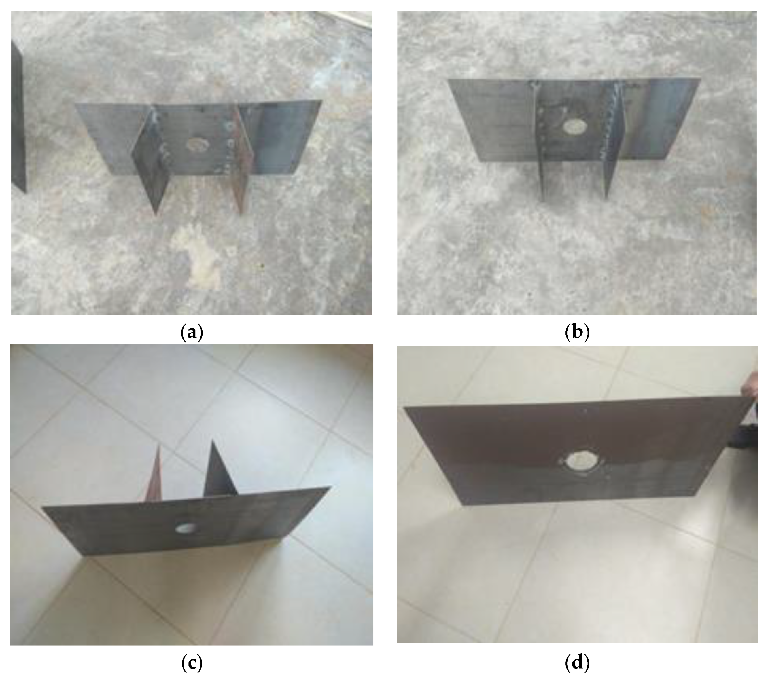
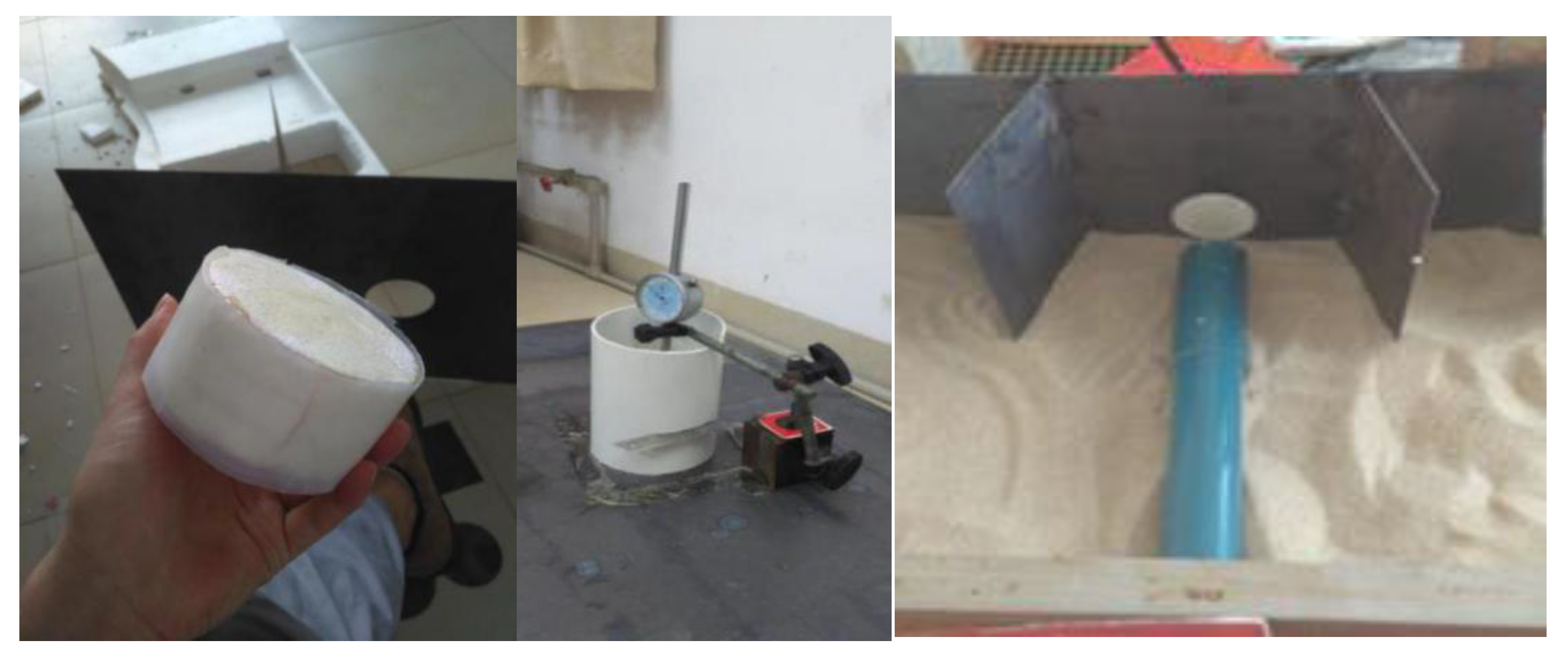
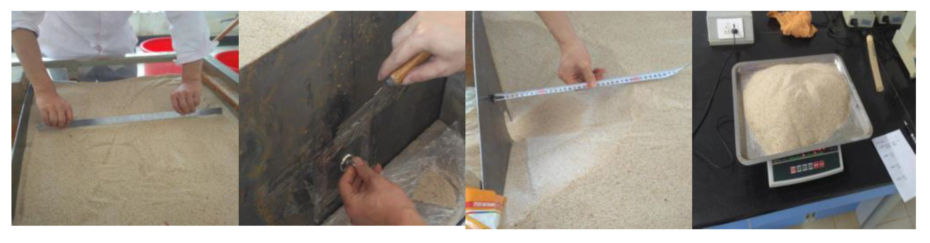
2.1. Model Test
2.1.1. Small Displacement Test
2.1.2. Large Displacement Test
2.2. Numerical Simulation
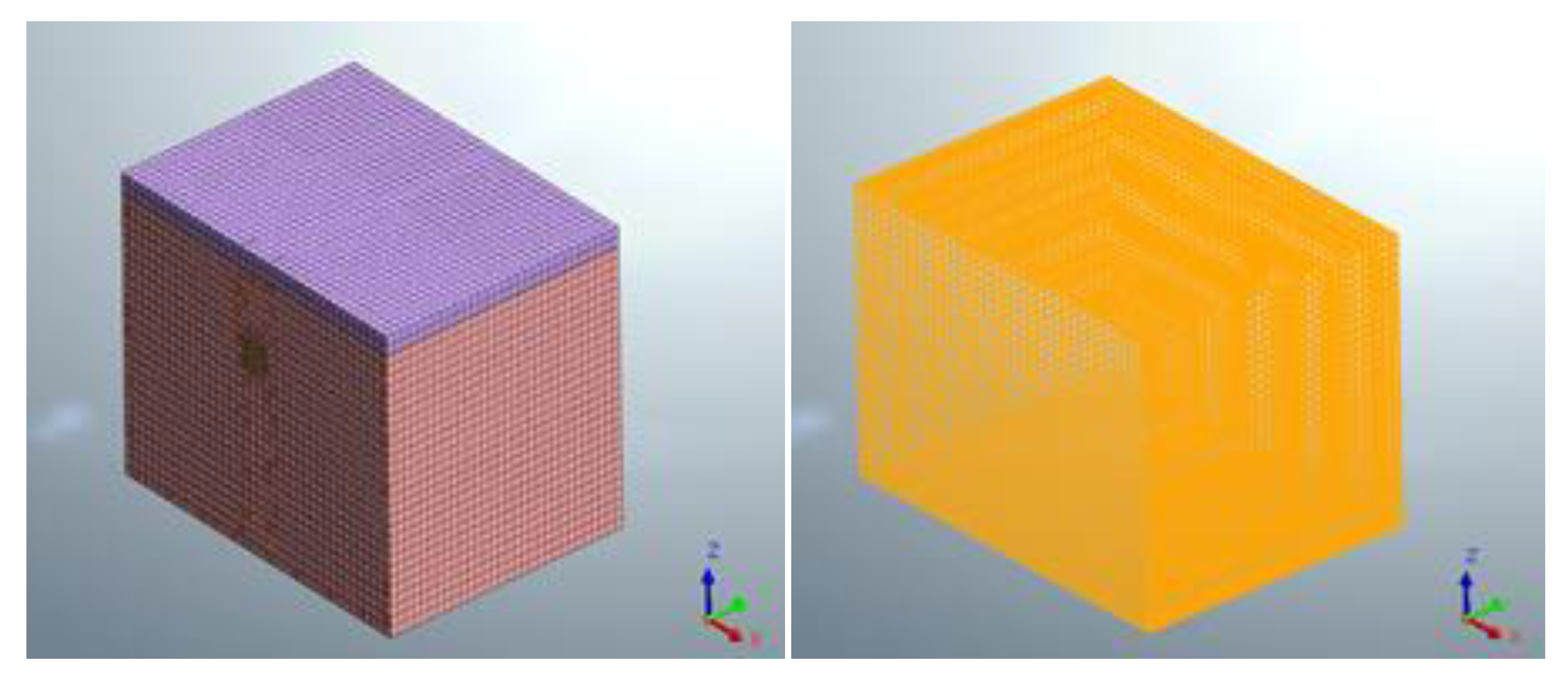
2.2.1. Assumptions
- It was considered that the soil behind the retaining wall was uniformly distributed at each layer, and the loss of material due to overexcitation and voids outside the tunnel perimeter was not considered;
- Intermittences during shield construction were not considered, and it was assumed that the shield machine advanced continuously with continuous palm pressure;
- The mechanical properties of the soil were maintained during the excavation process, regardless of regional discontinuities;
- The initial ground stress was calculated based on only the self-weight stress of the soil without considering the tectonic stress or vibrations of the shield machine on the soil body during excavation;
- The soil was isotropic elastic plastic, and its intrinsic relationships were determined by the modified Mohr–Coulomb criteria.
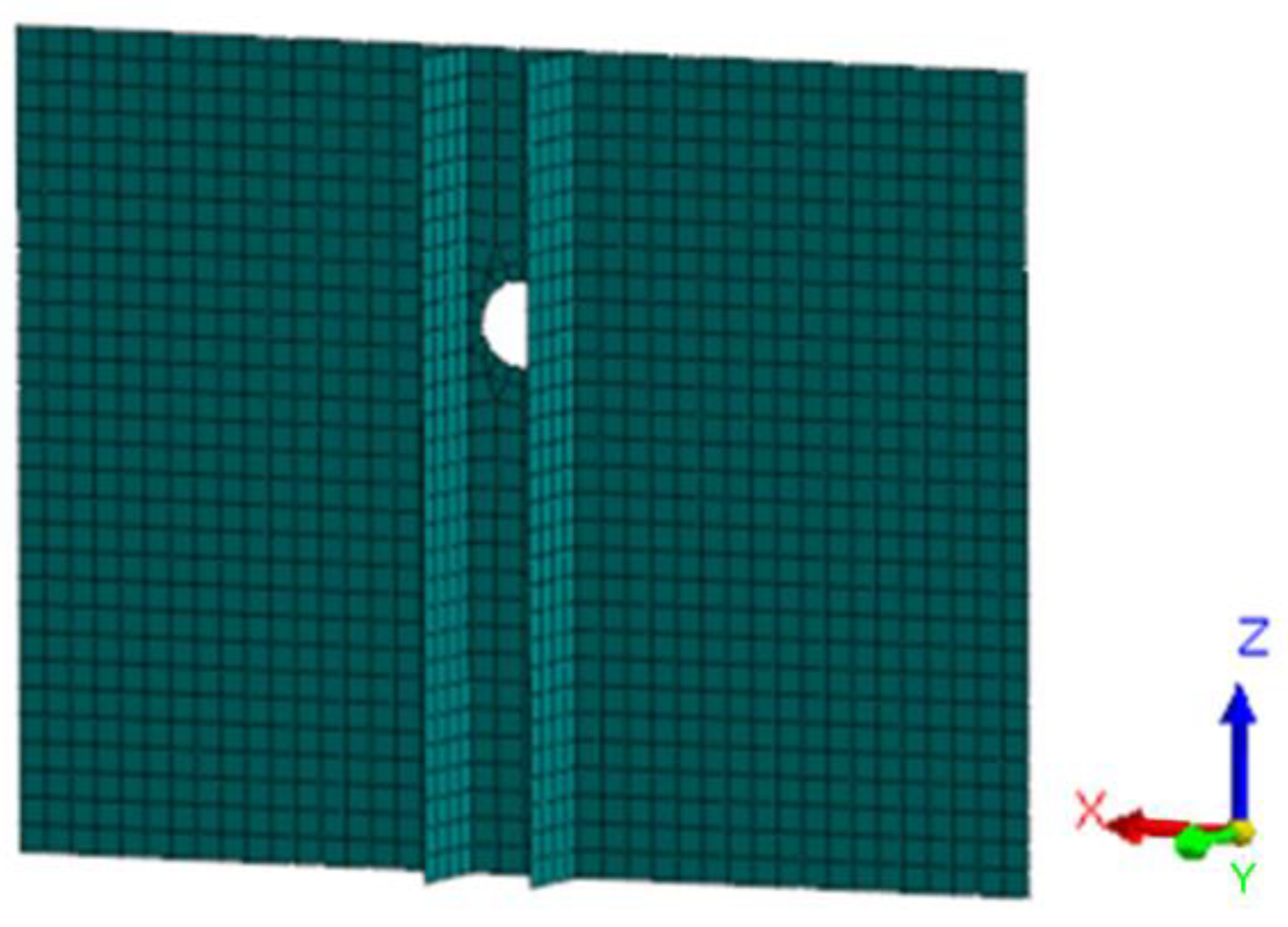
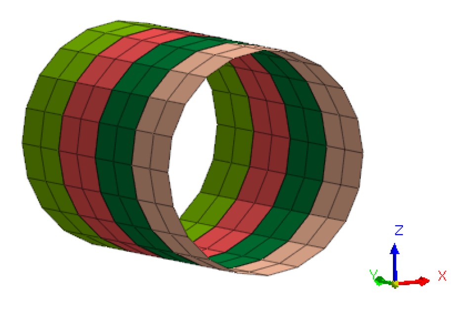
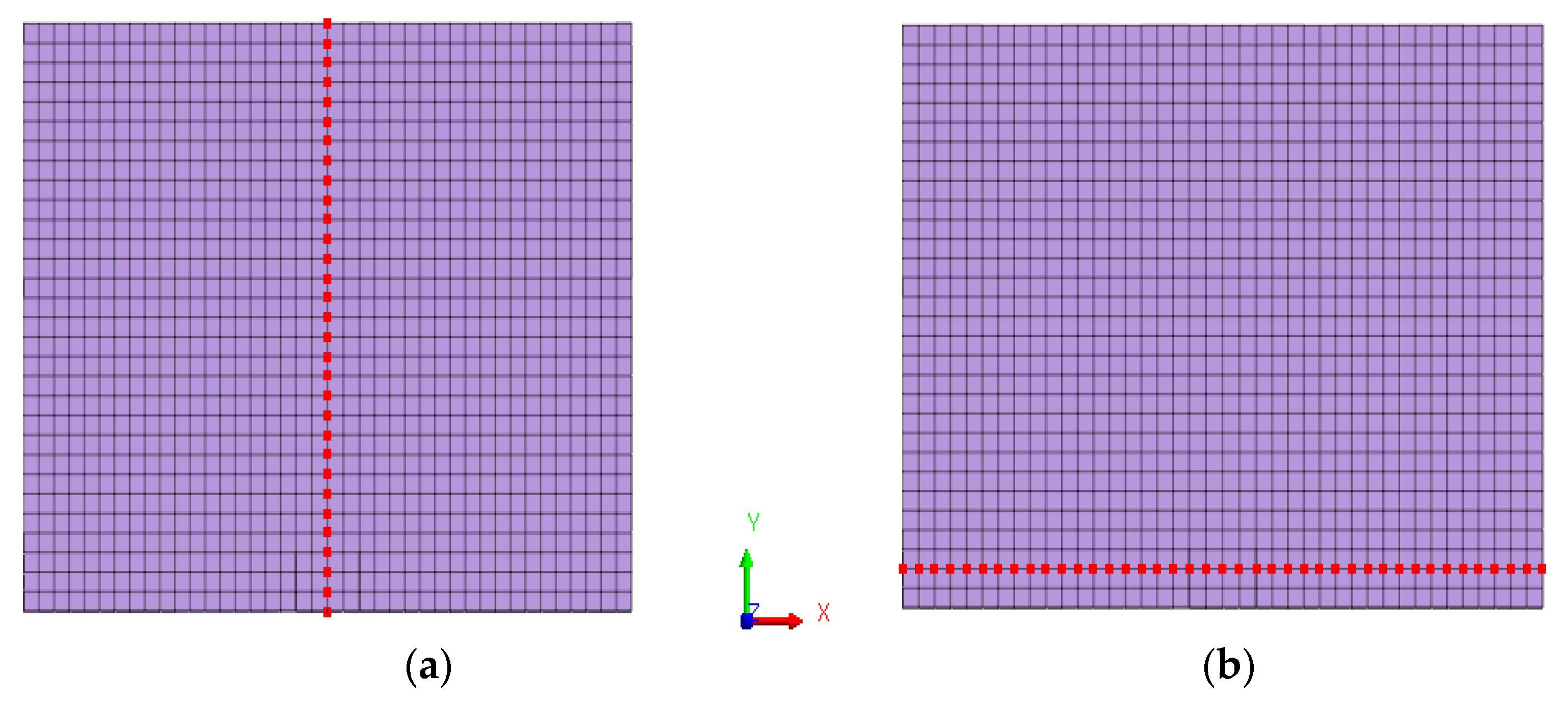
2.2.2. Model Building
3. Results and Analysis
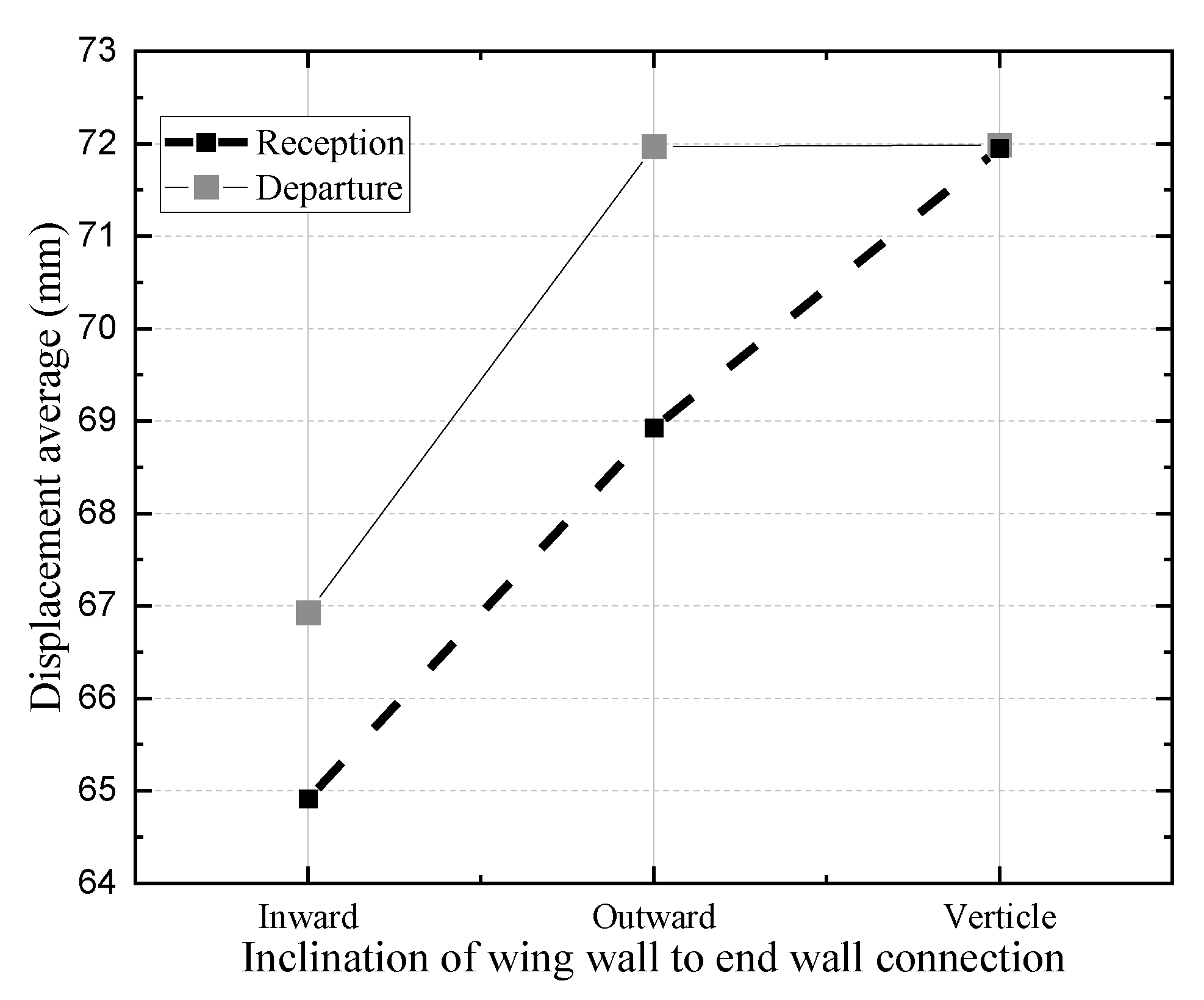
3.1. Effect of Wing Wall Length on Stress Distribution during Departure and Reception of Shield
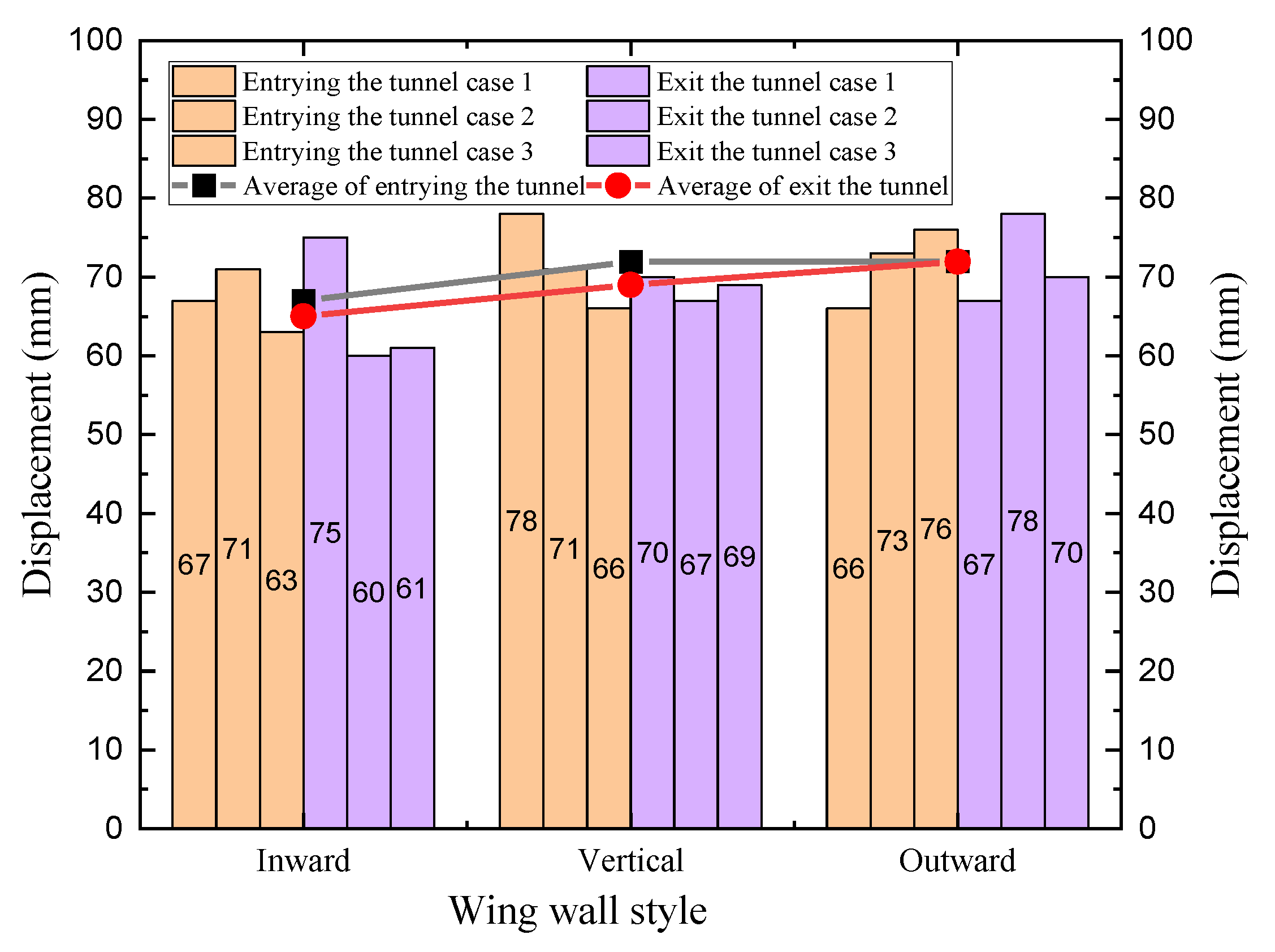
3.1.1. Small Displacement Model Test Results and Analysis
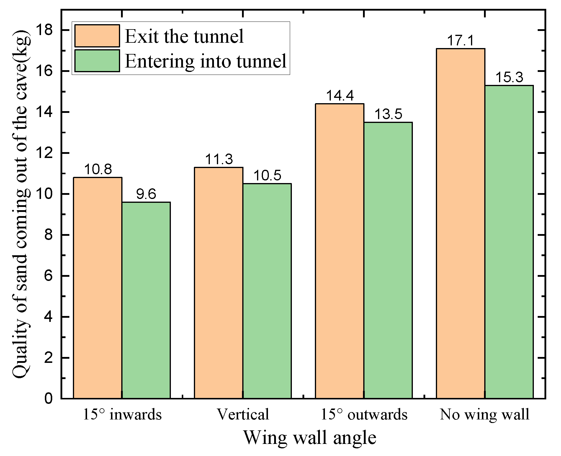
3.1.2. Large Displacement Model Test Results and Analysis
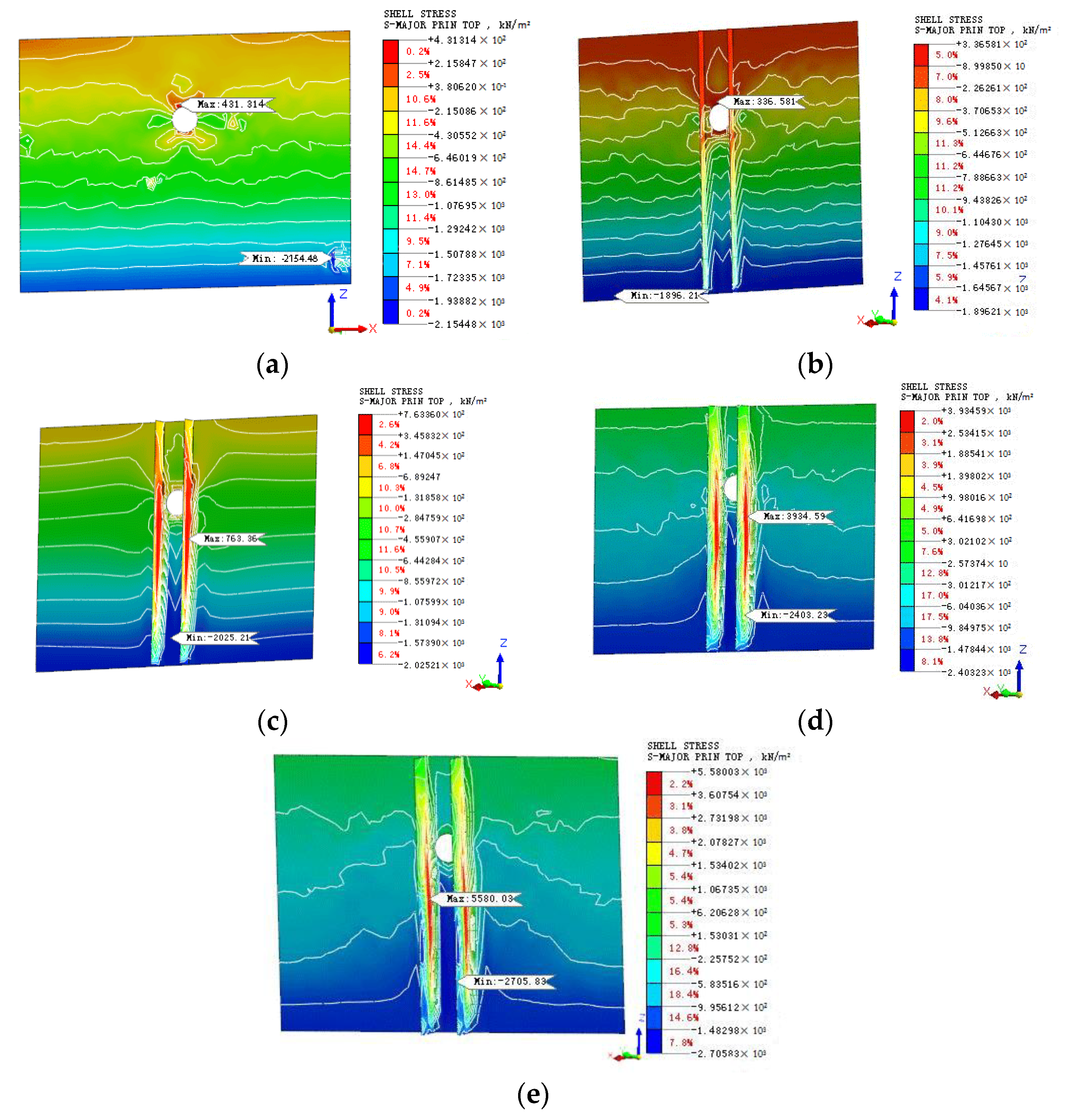
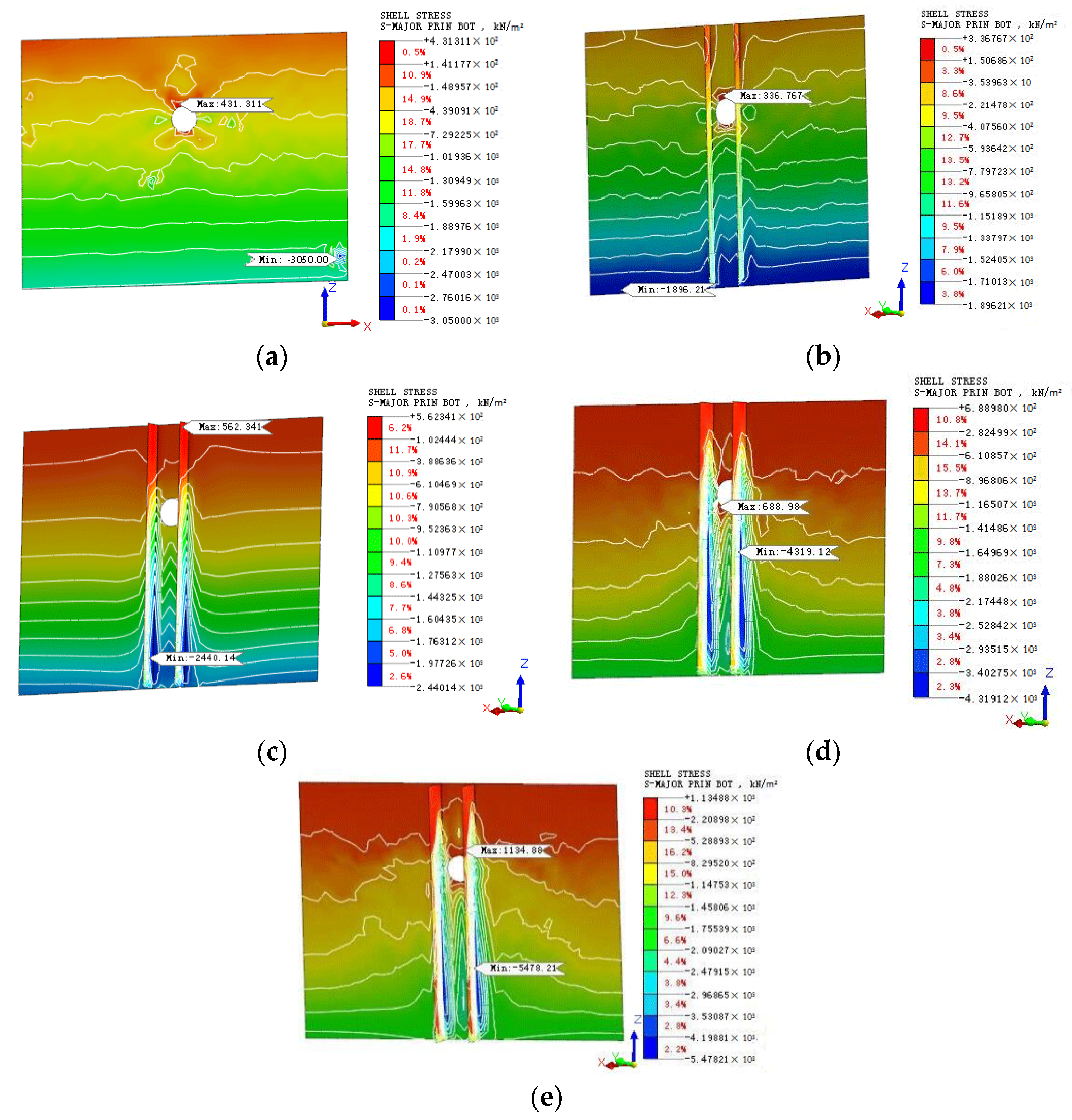
3.2. Influence of Wing Wall Length on the Stress Distribution within the Diaphragm Wall during Shield Initiation and Reception
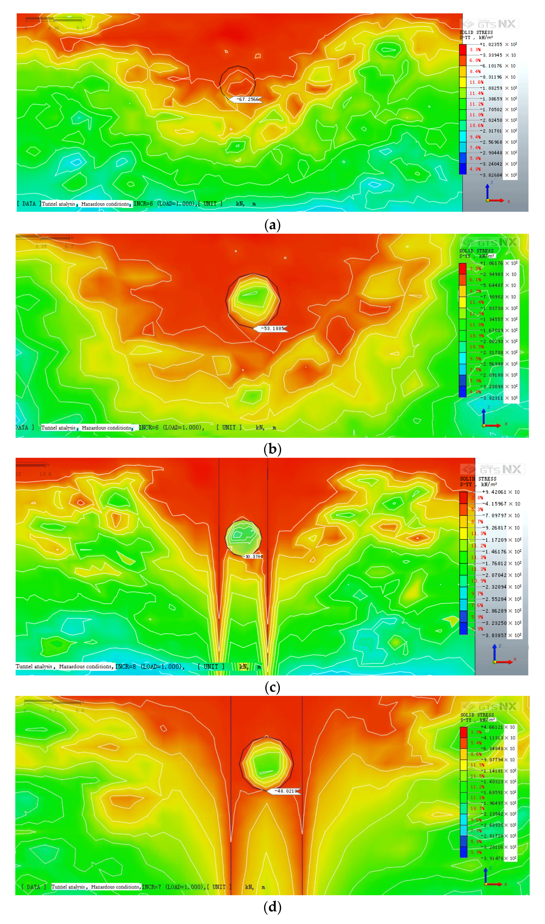
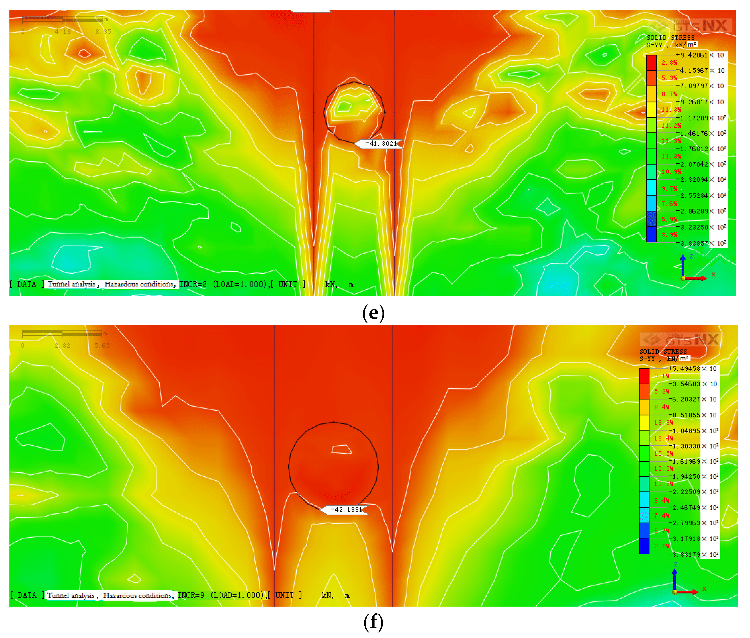
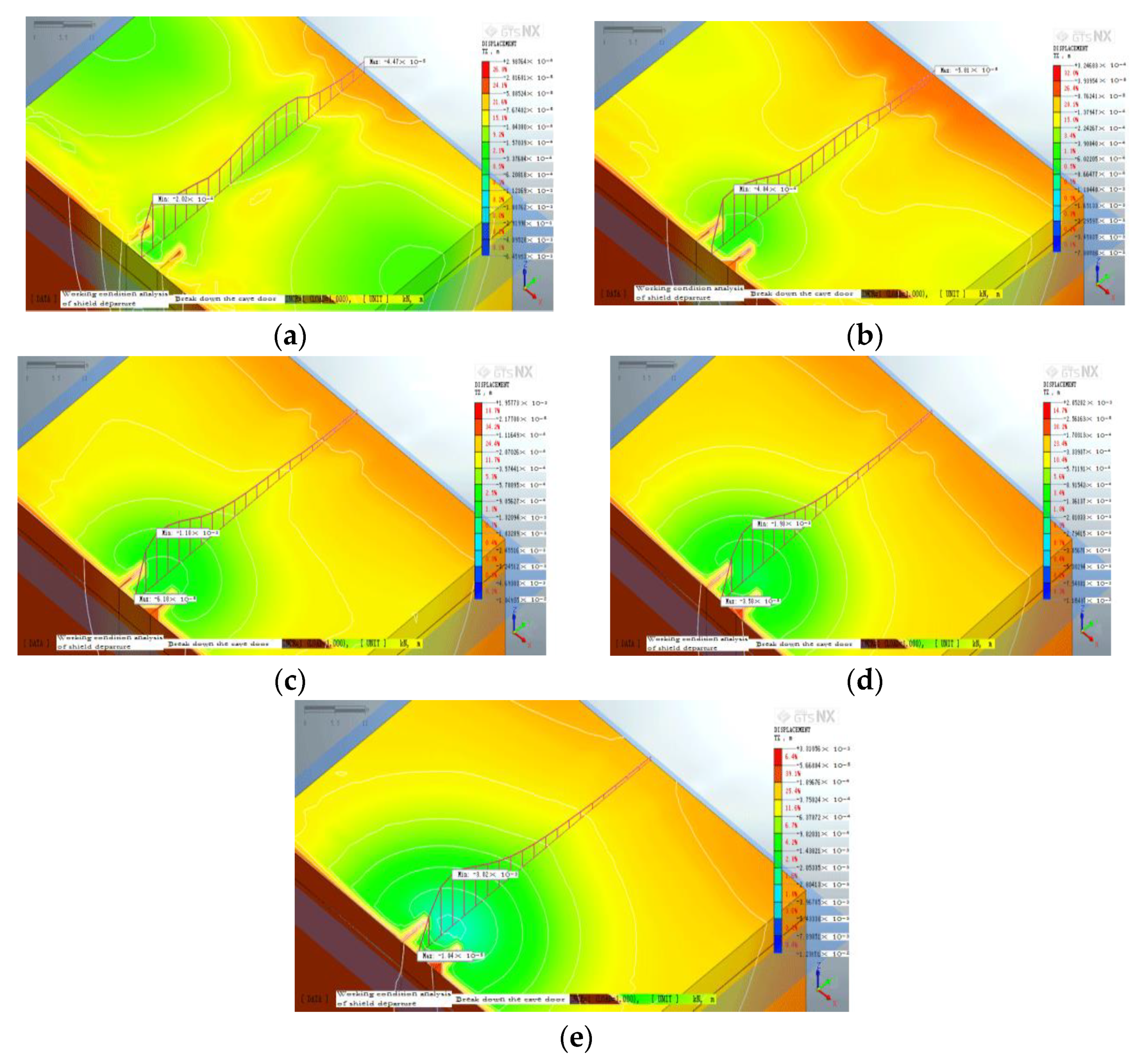
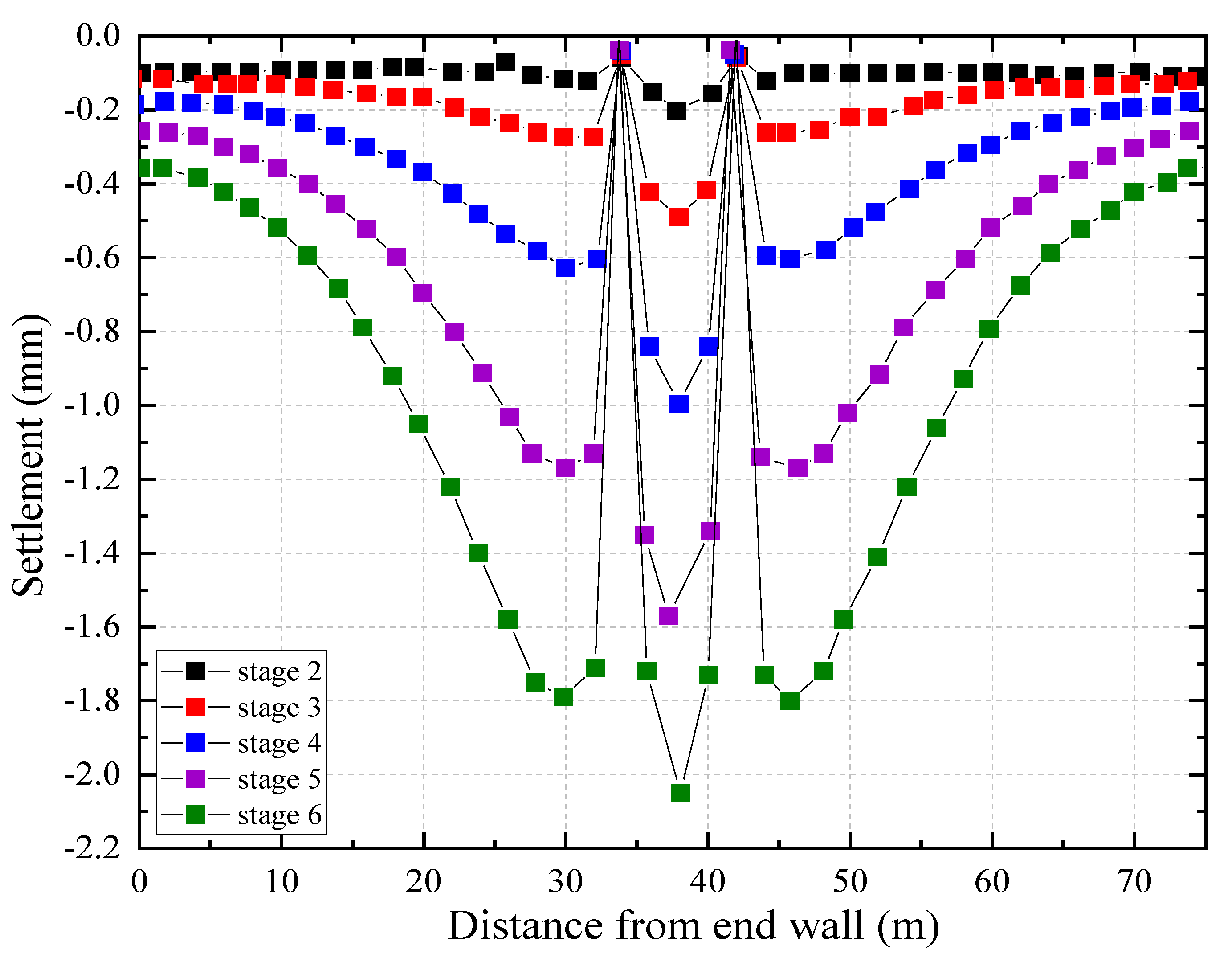
3.3. Surface Settlement and Internal Stress Distribution in Diaphragm Wall at Different Stages of Construction
4. Conclusions
Author Contributions
Funding
Institutional Review Board Statement
Data Availability Statement
Conflicts of Interest
References
- Bilotta, E. Use of diaphragm walls to mitigate ground movements induced by tunneling. Géotechnique 2008, 58, 143–155. [Google Scholar] [CrossRef]
- Bilotta, E.; Russo, G. Use of a Line of Piles to Prevent Damages Induced by Tunnel Excavation. J. Geotech. Geoenviron. Eng. 2011, 137, 254–262. [Google Scholar] [CrossRef]
- Bilotta, E.; Taylor, R.N. Centrifuge modeling of tunneling close to a diaphragm wall. Int. J. Phys. Model. Geotech. 2005, 5, 27–41. [Google Scholar] [CrossRef]
- Bilotta, E.; Stallebrass, S.E. Prediction of stresses and strains around model tunnels with adjacent embedded walls in overconsolidated clay. Comput. Geotech. 2009, 36, 1049–1057. [Google Scholar] [CrossRef] [Green Version]
- Mironov, D.A.; Osokin, A.I.; Loseva, E.S.; Kuzhelev, A.I. Specific features of diaphragm wall construction. IOP Conf. Ser. Mater. Sci. Eng. 2020, 775, 012051. [Google Scholar] [CrossRef] [Green Version]
- Wyjadłowski, M.; Muszyński, Z.; Kujawa, P. Application of Laser Scanning to Assess the Roughness of the Diaphragm Wall for the Estimation of Earth Pressure. Sensors 2021, 21, 7275. [Google Scholar] [CrossRef] [PubMed]
- Alsahly, A.; Stascheit, J.; Meschke, G. Advanced finite element modeling of excavation and advancement processes in mechanized tunneling. Adv. Eng. Softw. 2016, 100, 198–214. [Google Scholar] [CrossRef]
- Dun, Z.L.; Cao, Y.; Ren, L.W. Risk Analysis during Departure and Reception of Shield in the Yellow River Crossing Tunnel of the Middle Route Project of South-to-North Water Diversion. Appl. Mech. Mater. 2011, 90–93, 2125–2130. [Google Scholar] [CrossRef]
- Broms, B.B.; Bennermark, H. Stability of Clay at Vertical Opening. J. Soil Mech. Found. Div. 1967, 93, 71–94. [Google Scholar] [CrossRef]
- Bakker, K.J.; Bezuijen, A.; Broere, W.; Kwast, E.A. Geotechnical Aspects of Underground Construction in Soft Ground. In Proceedings of the 5th International Symposium TC28, Amsterdam, The Netherlands, 15–17 June 2005; CRC Press: Boca Raton, FL, USA, 2013. [Google Scholar]
- Komiya, K.; Shimizu, E.; Watanabe, T.; Kodama, N. Earth pressure exerted on tunnels due to the subsidence of sandy ground. In Geotechnical Aspects of Underground Construction on Soft Ground; A. A. Balkema: Rotterdam, The Netherlands, 2000. [Google Scholar]
- Comodromos, E.M.; Papadopoulou, M.C.; Konstantinidis, G.K. Effects from diaphragm wall installation to surrounding soil and adjacent buildings. Comput. Geotech. 2013, 53, 106–121. [Google Scholar] [CrossRef]
- Gunn, M.J.; Clayton, C.R.I. Installation effects and their importance in the design of earth-retaining structures. Géotechnique 1992, 42, 137–141. [Google Scholar] [CrossRef]
- Wu, G.; Chen, W.; Bian, H.; Yuan, J. Structure optimisation of a diaphragm wall with special modelling methods in a large-scale circular ventilating shaft considering shield crossing. Tunn. Undergr. Space Technol. 2017, 65, 35–41. [Google Scholar] [CrossRef]
- Gang, W.; Yu, S. Effect Analysis of Double-O-Tube Shield Tunnel Crossing Masonry Structure Building with 45°. In Proceedings of the 2012 Second International Conference on Electric Technology and Civil Engineering, ICETCE ’12, Yichang, China, 18–20 May 2012; IEEE Computer Society: Washington, DC, USA, 2012; pp. 1028–1031. [Google Scholar]
- Sirivachiraporn, A.; Phienwej, N. Ground movements in EPB shield tunneling of Bangkok subway project and impacts on adjacent buildings. Tunn. Undergr. Space Technol. 2012, 30, 10–24. [Google Scholar] [CrossRef]
- Wei, G. Numerical Simulation of Shield Tunnel Crossing Masonry Structure Building with Various Degrees. Adv. Mater. Res. 2012, 368–373, 889–893. [Google Scholar] [CrossRef]
- Xu, Q.; Zhu, H.; Ma, X.; Ma, Z.; Li, X.; Tang, Z.; Zhuo, K. A case history of shield tunnel crossing through group pile foundation of a road bridge with pile underpinning technologies in Shanghai. Tunn. Undergr. Space Technol. 2015, 45, 20–33. [Google Scholar] [CrossRef]
- Yamaguchi, I.; Yamazaki, I.; Kiritani, Y. Study of ground-tunnel interactions of four shield tunnels driven in close proximity, in relation to design and construction of parallel shield tunnels. Tunn. Undergr. Space Technol. 1998, 13, 289–304. [Google Scholar] [CrossRef]
- Pang, Y.; Zhang, P.; Gao, D.; Zhao, K.; Mo, F. Effects of winding way on mechanical properties of GFRP bar. J. Jiangsu Univ. Nat. Sci. Ed. 2014, 35, 589–594. [Google Scholar] [CrossRef]
- Robert, M.; Cousin, P.; Benmokrane, B. Durability of GFRP Reinforcing Bars Embedded in Moist Concrete. J. Compos. Constr. 2009, 13, 66–73. [Google Scholar] [CrossRef] [Green Version]


| Material Parameters | Mixed Fill | Clay | C30 | C50 |
|---|---|---|---|---|
| Elastic modulus (kN/m2) | 6220 | 16,100 | 3 × 10⁷ | 3.45 × 10⁷ |
| Poisson’s ratio | 0.37 | 0.33 | 0.2 | 0.2 |
| Weight capacity (kN/m3) | 17 | 20.3 | 25 | 25 |
| Cohesion (kN/m2) | 18 | 48 | / | / |
| Friction angle (°) | 6 | 12 | / | / |
| Drainage parameters | Drainage | Drainage | / | / |
| Ontogenetic model | Modified Mohr–Coulomb | Modified Mohr–Coulomb | Elastic | Elastic |
Publisher’s Note: MDPI stays neutral with regard to jurisdictional claims in published maps and institutional affiliations. |
© 2022 by the authors. Licensee MDPI, Basel, Switzerland. This article is an open access article distributed under the terms and conditions of the Creative Commons Attribution (CC BY) license (https://creativecommons.org/licenses/by/4.0/).
Share and Cite
Huang, R.; Hu, J.; Pan, J.; Wu, Y.; Ren, X.; Zeng, D.; Wang, Z.; Wang, S. The Π-Formed Diaphragm Wall Construction for Departure and Reception of Shield Machine. Sustainability 2022, 14, 7653. https://doi.org/10.3390/su14137653
Huang R, Hu J, Pan J, Wu Y, Ren X, Zeng D, Wang Z, Wang S. The Π-Formed Diaphragm Wall Construction for Departure and Reception of Shield Machine. Sustainability. 2022; 14(13):7653. https://doi.org/10.3390/su14137653
Chicago/Turabian StyleHuang, Rui, Jun Hu, Jingbo Pan, Yuwei Wu, Xingyue Ren, Dongling Zeng, Zhixin Wang, and Shucheng Wang. 2022. "The Π-Formed Diaphragm Wall Construction for Departure and Reception of Shield Machine" Sustainability 14, no. 13: 7653. https://doi.org/10.3390/su14137653