Article

Novel Combined Load Frequency Control and Automatic Voltage Regulation of a 100% Sustainable Energy Interconnected Microgrids

1
Faculty of Engineering, Heliopolis University, Cairo 11785, Egypt
2
Department of Mechanical Engineering, Faculty of Engineering, ‘Dunarea de Jos’ University of Galati, 47 Domneasca Street, 800008 Galati, Romania
*
Author to whom correspondence should be addressed.
Sustainability 2022, 14(15), 9428; https://doi.org/10.3390/su14159428
Submission received: 14 June 2022 / Revised: 23 July 2022 / Accepted: 30 July 2022 / Published: 1 August 2022

Abstract

:
Frequency and voltage deviations are two main problems in microgrids, especially with the increase in the penetration level of renewable energies. This paper presents novel techniques to apply combined the load frequency control and automatic voltage regulation of two interconnected microgrids. The two microgrids are operated by solar energy and bioenergy technologies and include energy-storage facilities. The control is applied using a novel accelerating PID controller (PIDA), which is compared to state-of-the-art control schemes. The controllers are designed using a new doctor and patient optimization technique (DPO), which is compared to state-of-the-art techniques. The combined design of load frequency controllers and automatic voltage regulators is also compared to a standalone design. The comparisons are carried out by testing the system performance at each operation condition in addition to indicators such as integral absolute error for frequency and voltage and integral time absolute error for frequency and voltage. The results show that a combined DPO–PIDA design of LFC–AVR schemes for fully sustainable microgrids has better performance than other standalone designs and other control and optimization alternatives.

1. Introduction

There has been a considerable interest in turning grids to 100% renewable energies. Many countries in Asia and Africa are working towards creating a high penetration level of renewables through solar energy and bioenergy technologies [1,2]. The idea behind using solar and bioenergy technologies is the presence of the high amount of waste in those countries in addition to the high solar potential [3,4,5].
Automatic voltage regulation (AVR) is highly important in a power system to avoid under- and over-voltage occurrences [6]. AVR offers optimal power system operation by minimizing active and reactive power losses. The AVR is implemented by tracking a steady reference through controllers and actuators [7].
Load frequency control (LFC) is very important in terms of power system security. Most historical blackouts resulted from under/over-frequency events. LFC schemes gives the chance to minimize frequency oscillations and deviations from spreading among power system areas [8].
Many controllers are used either in LFC or AVR such as the proportional integral derivative (PID) control scheme [9], nonlinear PID (NPID) [10], and fractional order PID (FOPID) [11]. The comparison between those controllers proved that the increase in the control variables leads the system to better performance. In [12], the nonlinear FOPID (NFOPID) control scheme is presented as a hybrid controller between NPID and FOPID.
Microgrids are considered as the most applicable solution in places where there is difficulty in reaching the national or regional power systems. It is a hot research topic to operate microgrids with only renewable energies, due to the variability that could affect system frequency and voltage. In [12,13], the authors applied load frequency control on 100% renewable energy interconnected microgrids using novel nonlinear fractional order PID control. In [14], the authors applied automatic generation control in a fully sustainable marine microgrid, using tidal supplementary control in the form of fractional integrators. In [12,13,14], the research did not consider the voltage problems and did not afford any solutions to it. In [15], the authors applied secondary voltage control in a power system with fully renewable power generation using a neural network and a genetic algorithm, but the research did not consider possible ways to control the frequency.
With the increase in the penetration level of renewables, there are the problems of voltage and frequency deviations that may lead to a blackout, so the coupling between LFC and AVR increases due to the high degree of uncertainty and nonlinearity [16]. In [17], the authors proposed the design of a nonlinear threshold accepting PID, based on a combined AVR–LFC scheme for a conventional multi-area power system. The results proved that the applied technique behaves better than other optimization techniques. In [18], the authors presented particle swarm PID based on a combined LFC–AVR scheme for a multi-area system. In [19], the authors applied lightning search FOPID based on a combined LFC–AVR scheme for a multi-area system. The multi-area system includes conventional and renewable resources. The results proved that lightning search FOPID drives the system to better performance than other techniques. In [20], authors presented a novel technique to control a multi-area power system with coupled LFC–AVR, but the system consisted of conventional and renewable energy technologies. In [21], authors compared the performance of the load frequency control with and without the presence of AVR, but the application was applied in a conventional generation system.
All the previous research papers [12,13,14,15,16,17,18,19,20,21] highlight solutions to optimally design load frequency controllers and/or automatic voltage regulators in the presence of different penetration levels of renewable energies. None of them studied the combined design of LFC and AVR in interconnected microgrids with a 100% penetration level of renewable energies.
In [22], Mohammad Dehghani et al. proposed a new doctor and patient algorithm (DPO) optimization technique. The new technique for state-of-the-art optimization techniques proved better performance than, namely the particle swarm (PSO) algorithm [23], the grasshopper optimization (GOZ) algorithm [24], and the socio evolution & learning optimization (SELO) algorithm [25].
The main contributions of this paper are:
  • Application of an LFC–AVR scheme on a multi-area system with 100% renewable energy.
  • Proposal of a novel controller, which is an accelerating PID (PIDA), in comparison with the state-of-the-art control schemes, namely FOPID, NPID, and PID.
  • Application of DPO as a new optimization technique in comparison with the state-of-the-art techniques.
  • Comparison between separate and combined designs of LFC and AVR.
  • Proposal of a new cost function for the controllers’ design.
The rest of the paper is organized as follows: Section 2 describes the configuration of the studied 100% renewable energy multi-area system. Section 3 discusses the LFC–AVR scheme and PIDA controller. Section 4 illustrates the optimization problem and the novel optimization technique. Section 5 presents the simulation results, while Section 6 presents a discussion on the results, and Section 7 illustrates the main conclusion.

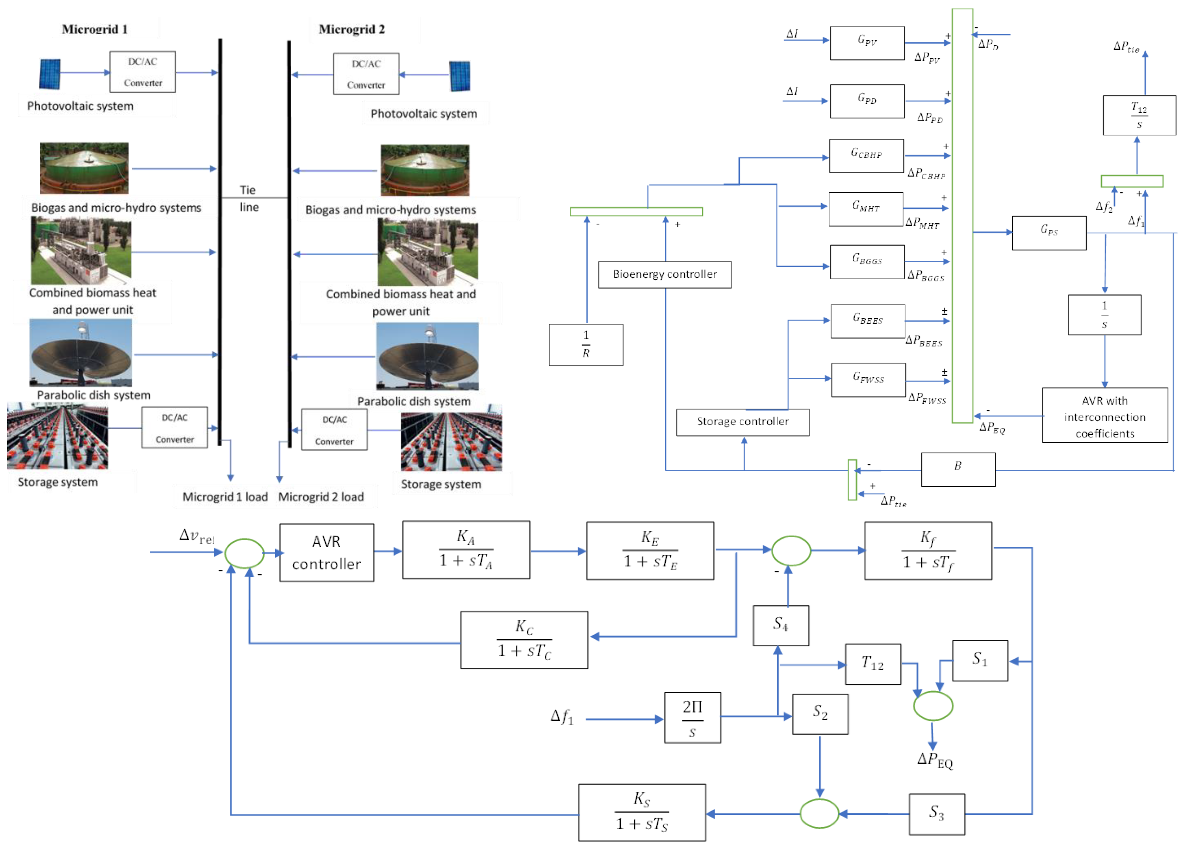
2. 100% Renewable Energy Interconnected Microgrids

Many locations in Africa have no electricity access, yet are rich with waste and sun as resources for energy transformation. Therefore, Africa is a cultivated land for demonstrating fully renewable energy microgrids in agriculture and industrial communities. Marine communities are also particularly good candidates to employ 100% renewable energy, since seas and oceans are rich with marine biomass, and the sun is also always present there. In this research, each microgrid is consisting of three bioenergy technologies and two solar energy facilities in addition to storage. The bioenergy technologies are a combined biomass heat and power unit, a biogas unit, and a micro-hydro turbine unit. The solar energy units are a photovoltaic unit and a parabolic dish unit. Battery energy storage technology is used to store and generate electricity. Figure 1 shows the two interconnected microgrids used in agriculture and marine communities, including the LFC–AVR combined model of the interconnected system. All the names of the parameters and variables that are written in Equations (1)–(21) are illustrated in Table 1.

2.1. Bioenergy Technologies

Bioenergy technologies are mainly focusing on converting different types of wastes to electrical energy.

2.1.1. Combined Biomass Heat and Power Unit (CBHP)

The unit converts solid waste into electricity through the following transfer function (1), which includes a steam turbine, reheater, and speed governor.
G CBHP = K B C 1 + s T B C 1 + s K R T R 1 + s T R   1 1 + s T B C T
where K B C is the participation factor of CBHP, T B C is time constant of the speed governor, K R is turbine gain, T R is time constant of the turbine, and T B C T is time constant of the reheater.

2.1.2. Micro-Hydro Turbine Unit (MHT)

The unit converts wastewater into electric energy, modeled through the transfer function in (2), which includes a penstock speed regulator and a micro-hydro turbine.
G MHT = K M G 1 + s T H G 1 + s T R S 1 + s T R H   1 s T H T 1 + 0.5 s T H T
where K M G is the participation factor of MHT, T H G is transient droop, T R S is governor delay, T R H is reset, and T H T is turbine delay.

2.1.3. Biogas Unit (BG)

The unit converts the animal wastes to electricity, modeled through the transfer function in (3), which includes an inlet valve, combustor, and turbine.
G B G G S = K B G G S 1 + s X c ( 1 + s Y c ) ( 1 + s b B )   .   1 + s T C R 1 + s T B G . 1 1 + s T B T
K B G G S is the participation factor of BG, T C R is combustion reaction delay, T B G is biogas delay, X c is lead time, Y c is lag time, b B is valve actuator, and T B T is discharge time constant.

2.2. Solar Energy Technologies

Solar energy technologies have a high growing rate among other renewable energy systems. The most two famous technologies are photovoltaics (PV) and concentrated solar power (CSP). A parabolic dish (PD) is one of the types of CSP.

2.2.1. PV Unit

A PV unit converts the solar radiation into electricity. The unit is modeled using the transfer function in (4), which includes radiation, temperature, area, and efficiency.
G PV = Δ P P V Δ I   = 1 1 + T P V s
where T P V is PV time constant.

2.2.2. PD Unit

A PD unit concentrates solar energy at a point with 40% to 60% efficiency. The unit is modeled using the transfer function in (5).
G PD = Δ P P D Δ I   = K P D 1 + T P D s
where K P D is PD gain, and T P D is PD time constant.

2.3. Energy Storage Systems

Each microgrid has two storage technologies, namely a battery storage system and a flywheel storage system. The transfer function of the battery energy and flywheel energy systems is shown in (6) and (7), respectively.
G B E S S = K B E S S 1 + T B E S S s
G F W S S = K F W S S 1 + T F W S S s
where  K B E S S and T B E S S are the battery system’s gain and time constant, respectively, while K F W S S and T F W S S are the flywheel system’s gain and time constant, respectively.

2.4. Microgrids Equations

The following equations illustrate the microgrids generation, demand and interconnection powers.
Δ P e =   P P V + P D G + P M H T + P B G + P C B H P ± P B E S S ± P F W S S P D ± Δ P t i e
Δ P t i e = T 12 s   ( Δ f 1 Δ f 2 )
G P S = Δ f Δ P e   = 1 D + M e q s
B = 1 R + D
where M e q is the microgrid inertia, D is the damping constant of the microgrid, B is the frequency bias factor, and T 12 is the synchronized power.

3. System Control

3.1. LFC and AVR Interconnection

In large power grids, it is very rare to find a considerable relation between the change of voltage and the change in frequency, so it is neglected. In microgrids, the volage and frequency changes are considered and modeled as shown in Equations (12)–(18)
Δ P E Q = T 12 Δ δ + S 1 Δ E f
Δ v = S 2 Δ δ + S 3 Δ E f
Δ E f = K f 1 + s T f ( S 4 Δ δ + Δ E e )
Δ E e = K A 1 + s T A K E 1 + s T E Δ O 1
Δ E u = Δ v r e f s K C 1 + s T C Δ E e K s 1 + s T s Δ v 1
Δ O 1 = ( K P 1 + K I 1 s + K D 1 s )   Δ E u
Δ O 2 = ( ( K P 2 + K I 2 s + K D 2 s ) 1 R )   Δ f
where S 1 , S 2 , are coupling coefficients of AVR, K A , T A , K E , T E , K f , T f , K C , T C ,   K s , and T s are amplifier, exciter, field, compensator, sensor gains, and time constants of the AVR, respectively. Δ P E Q ,   Δ E f , Δ E e , and Δ E u are deviation in equivalent power due to AVR, field response, exciter response, and error in voltage, respectively.

3.2. Control Schemes

Different control schemes are applied to the system to control frequency, voltage and tie-line power. PID is used in previous work such as [12]. In [13], the authors applied control using FOPID and NPID controllers. The FOPID and NPID controllers transfer functions shown in (19) and (20). This paper presents a novel control scheme which is accelerating PID (PIDA). The controller has a transfer function shown in (21). The PIDA controller has 7 parameters which increase the flexibility if the controller which may drive the system to better performance.
G F O P I D = K P + K I s λ + K D s µ
G N P I D = ( K P + K I s + K D s )   e ( G x E ) + e ( G x E ) 2
G P I D A = K C 1 s 3 + K C 2 s 2 + K C 3 s + K C 4 K C 5 s 2 + K C 6 s + K C 7
where K P , K I , and K D are PID controller gains, λ and µ are integral and derivative powers in the FOPID controller, respectively. G is nonlinear gain in NPID, while K C 1 , K C 2 , K C 3 , K C 4 ,   K C 5 ,     K C 6 , and K C 7 are PIDA controller gains.

4. Optimization Problem

4.1. Optimization Problem Definition

In this work, the objective is to reduce the frequencies, voltages, and tie-line power deviation. A new multi-objective function is developed to drive the system to better performance in terms of frequency and voltage. The function is the multiplication of time with the sum of derivatives of frequencies, voltages, and tie-line power.
F = min ( t ( Δ f 1 t + Δ f 2 t + Δ P t i e t + Δ v 1 t + Δ v 2 t ) )
The variables of the optimization problem are the controller’s parameters. The system includes six controllers, which are the AVR controller, bioenergy controller, and energy storage controller of each area. If a PIDA control scheme is going to be applied to the system, the number of variables is 42 compared to 30 in an FOPID control scheme and 24 in an NPID control scheme.
The constraints of the optimization process are the boundaries of each parameter of each controller. In an FOPID control scheme, the constraints are 0 ≤ λ ≤ 1 and 0 ≤ µ ≤ 1, while in an NPID controller, the constraint that must be considered is 0 ≤ G ≤ 1.

4.2. DPO Design

DPO is inspired from the treatment of patients at this time of uncertainty. The optimization method is a virtual representation of the stages of patients’ treatment. The three steps are vaccination, treatment, and surgery. The patients should be vaccinated to prevent infection in the first stage. The second step is that the patient takes medicine to deal with the virus or the infection. The third stage is surgery for patients in serious conditions.
The population of patients who need to be treated is represented in (23).
P = [ P 1 : P N | P 1 1 P 1 m : P i d : P N 1 P N m ]
where P is the patient population, P i is the i th patient, and P i d is the d th feature of the i th patient.   N is the number of patients, and m is the number of variables.
There are three stages to process and update. The updating takes place through (24)–(27).
d o s a g e i = 2 F i N F B e s t N
F i N = f i t i f w o r s t j = 1 N ( f i t j f w o r s t )
f w o r s t = max ( f i t ) & P w o r s t = P ( l o c a t i o n ( f w o r s t ) )
f b e s t = min ( f i t ) & P b e s t = P ( l o c a t i o n ( f b e s t ) )
where d o s a g e i is the vaccine dosage of patient i, F i N is the patient normalized fitness, F B e s t N is the best patient normalized fitness, and f w o r s t and f b e s t   are the worst and best patients’ objective function, respectively, while P w o r s t and P b e s t are the worst and the best patients’ positions, respectively.

4.2.1. Stage 1: Vaccination Stage

Community health protection is applied through vaccination, and the modeling of this stage is illustrated in (28).
v i d = r a n d × ( d o s a g e i × P i d P w o r s t d )  
where v i d is the ith patient, d is the dimension of vaccine, rand is a randomly selected number between 0 and 1, and P w o r s t d is the worst patient d dimension.

4.2.2. Stage 2: Drug Administration

In this stage, the doctor selects the suitable pharmaceuticals according to the patient state. The stage can be modeled as shown in (29) and (30).
d i d = r a n d × ( P b e s t d d o s a g e i × P i d )
P i = { P i + d i ,   f i t ( P i + d i ) f i t i P i ,   e l s e
where d i d is the dimension d of a drug nominated to patient number I, while P b e s t d is the best patient d dimension.

4.2.3. Stage 3: Surgery

For late conditions, vaccination and drugs are not enough, and the only way to let the patient improve is surgery. The stage is modeled in (31)
P i = { P i × 0.6 + P b e s t × 0.4 , F B e s t N F i N 0.9 F B e s t N P i ,   e l s e

4.3. Indicators

Integral absolute error for frequency and voltage (IAE), in addition to integral time absolute error for frequency and voltage (ITAE), are used as indicators to compare between controllers, tuning methods, and optimization techniques.
IAE = 0 T Δ f 1 + Δ f 2 + Δ P t i e + Δ v 1 + Δ v 2   dt  
ITAE = 0 T t     ( Δ f 1 + Δ f 2 + Δ P t i e + Δ v 1 + Δ v 2 )   dt

5. Simulation Results

5.1. Test 1: Comparison between Different Optimization Techniques

In this test, a comparison between different optimization techniques, namely DPO, PSO, GOZ, and SELO, is performed. A load increase by 1% is simulated 1 s after starting the simulation of the system. The parameters of all PID controllers in the combined LFC–AVR model are calculated using each optimization technique. Figure 2 shows the performance of the change in the frequencies, powers, and voltages of the system for each optimization technique. The results show that DPO drives the two interconnected microgrids to better performance. Figure 3 shows that novel DPO leads the system to a better objective function result, with less IAE and ITAE having a smaller number of iterations.

5.2. Test 2: Comparison between Different Control Schemes

In this test, a comparison between different controllers, namely PIDA, FOPID, and PID is performed by subjecting the two microgrids to a 10% increase in demand. The parameters of all controllers are calculated using the DPO optimization technique. Figure 4 shows the performance of the change in frequencies, powers, and voltages of the system at each optimization technique. The results show that DPO leads the two interconnected microgrids to better performance. Figure 5 shows that novel PIDA leads the system to a better objective function result, with better IAE and ITAE than the other state-of-the-art control schemes.

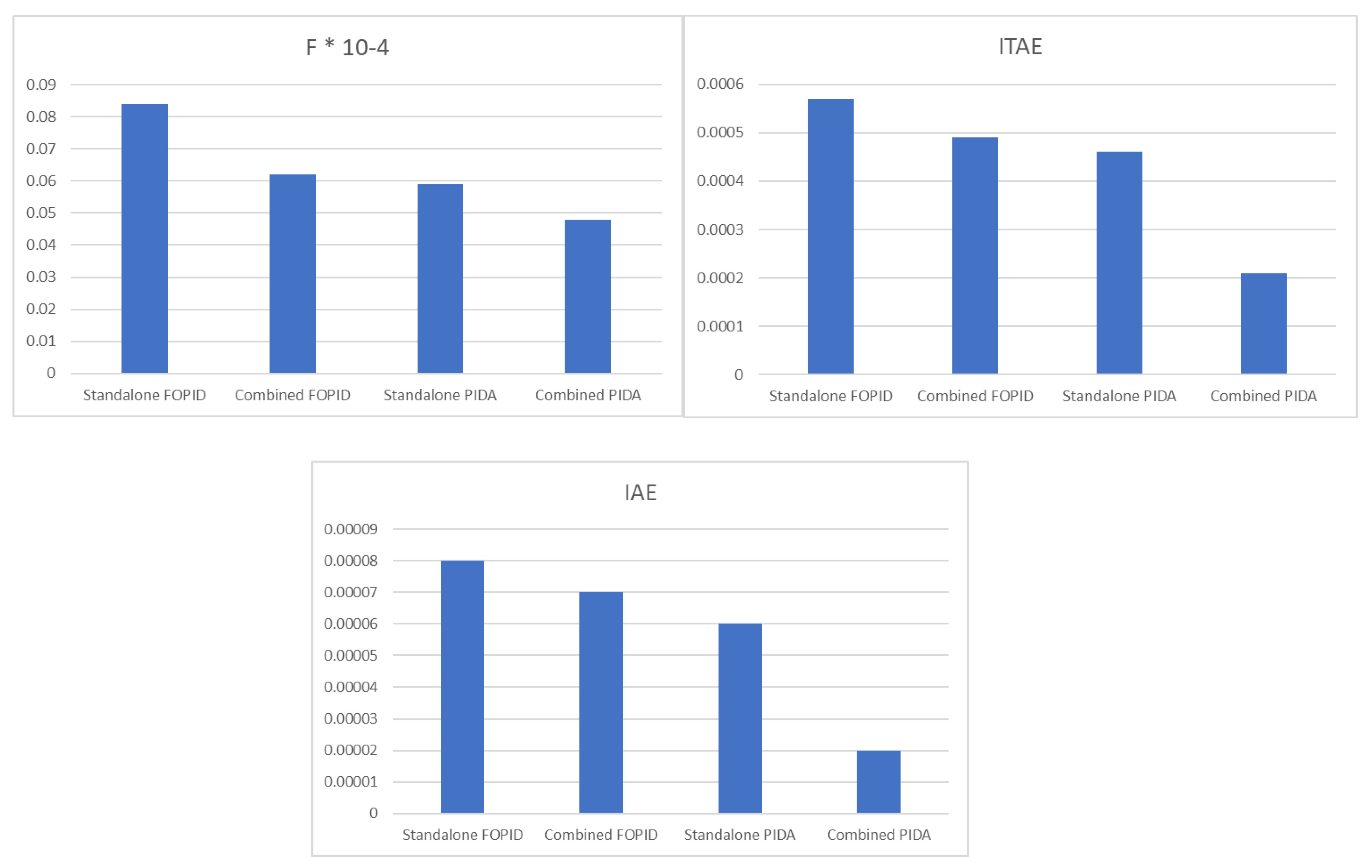
5.3. Test 3: Comparison between Combined Design of AVR-LFC Controllers and Standalone Design of AVR and LFC Controllers

In this test, a comparison between the design of AVR and LFC controllers at sthe ame time (combined) and a standalone design for AVR and LFC controllers (AVR controllers are designed, then LFC controllers are designed), when the two areas are subjected to the same real change in demand and solar power. The case study used in this test is SEKEM farm in ElWahat [26,27]. The parameters of all controllers are calculated using the DPO optimization technique. Figure 6 shows the performance of the change in frequencies, powers, and voltages of the system using combined PIDA, standalone PIDA, combined FOPID, and standalone FOPID controllers. The results show that combined PIDA controllers led the two interconnected microgrids to better performance than other alternatives. Figure 7 shows that using PIDA in a combined LFC–AVR model led the system to a better objective function result, with better IAE and ITAE than standalone models of AVR and LFC, plus the combined model is better than the standalone model in the case of using FOPID.
The results proved that applying a combined LFC–AVR design for PIDA using DPO will lead to better system performance in terms of frequency and voltage than the other alternatives and scenarios.

6. Discussions

The paper presented a combined model for LFC–AVR to improve the performance of two interconnected identical microgrids operated by 100% renewable energy technologies. The whole system is simulated according to Equations (1)–(21) in MATLAB SIMULINK version 2017A. The system is subjected to different case studies to compare between different control schemes and optimization techniques. The system is also examined in a real-case scenario.
The system is subjected to a 1% increase in demand in the two microgrids to compare between different optimization algorithms, namely DPO, which is a new algorithm, PSO, GOZ, and SELO. The results show that DPO is better than SELO, GOZ, and PSO in achieving the objective function, by 10%, 19%, and 37%, respectively. In terms of achieving less ITAE, DPO is better than SELO, GOZ, and PSO, by 11%, 18%, and 31%, respectively. The results also show that DPO is better than SELO, GOZ and PSO in achieving less ITAE, by 10%, 19%, and 37%, respectively. In terms of achieving less IAE, DPO is better than SELO, GOZ, and PSO, by 29%, 44%, and 62%, respectively.
The system is subjected to a 10% increase in the demand of each microgrid, to compare between different control schemes, namely PIDA, FOPID, NPID, and PID. The results show that PIDA drives the system to less objective function than FOPID, NPID, and PID, by 9%, 16%, and 29%, respectively. The results also show that PIDA drives the system to less IAE than FOPID, NPID and PID, by 13%, 17%, and 21%, respectively. The results show that PIDA drives the system to less ITAE than FOPID, NPID, and PID, by 34%, 39%, and 59%, respectively.
The system is subjected in test three to the real change in radiation and demand in SEKEM farm in ElWahat, which is located in western Egypt. The aim of this test is to compare the standalone design and the combined design of LFC–AVR. The results show that combined design led the system to better performance than the standalone design, by 18%, 58%, and 67%, in terms of objective function, ITAE, and IAE, respectively. The results also proved that the combined design of PIDA drives the system to better performance than the combined design of FOPID.
The simulated system is now turning to be implemented in the interconnected Egyptian farms in west Egypt, as a model for the whole of Africa to operate their farms using 100% sustainable energy technologies, employing sun and wastes as the main resources. The system is also valid for application in marine-isolated communities, since there is sun and marine wastes that can produce 100% green electricity, and by applying combined PIDA to LFC–AVR, the system reliability and performance will highly improve, to ensure a high quality of green electricity. The study will even help in achieving a 42% penetration level of renewable energies in Egypt by 2035, as planned by the government [28].

7. Conclusions

The paper studied the role of combined LFC–AVR on interconnected microgrids operated by fully sustainable energy solutions. The results proved that the design of combined AVR–LFC controllers drives the system to better performance than a standalone LFC and a standalone AVR, in terms of ITAE and IAE. The results also proved that a novel PIDA control scheme leads the system to better performance than FOPID, NPID, and PID control schemes, in terms of microgrids’ frequencies, powers, and voltages. The results also proved that the DPO optimization algorithm has better performance than other state-of-the-art algorithms, in terms of achieving better objective value, IAE, and ITAE, with a lower number of iterations during the control-scheme design process. The study also proved that biomass energy converters cover the changes in the demand and solar power more than energy storage systems.

Author Contributions

Conceptualization, H.H.F.; methodology H.H.F.; software, H.H.F.; validation, H.H.F.; formal analysis, H.H.F.; investigation, H.H.F.; resources, E.R.; data curation, H.H.F. and E.R.; writing—original draft preparation, H.H.F.; writing—review and editing, E.R.; visualization, E.R.; supervision, E.R.; project administration, H.H.F. and E.R.; funding acquisition, E.R. All authors have read and agreed to the published version of the manuscript.

Funding

This work was carried out in the framework of the research project DREAM (Dynamics of the REsources and technological Advance in harvesting Marine renewable energy), supported by the Romanian Executive Agency for Higher Education, Research, Development and Innovation Funding—UEFISCDI, grant number PN-III-P4-ID-PCE-2020-0008.

Institutional Review Board Statement

Not applicable.

Informed Consent Statement

Not applicable.

Data Availability Statement

No data except that in the paper.

Conflicts of Interest

The authors declare no conflict of interest.

References

  1. Barik, A.K.; Das, D.C. Expeditious frequency control of solar photovoltaic/biogas/biodiesel generator based isolated renewable microgrid using grasshopper optimisation algorithm. IET Renew. Power Gener. 2018, 12, 1659–1667. [Google Scholar] [CrossRef]
  2. Bai, C.; Sarkis, J. The Water, Energy, Food, and Sustainability Nexus Decision Environment: A Multistakeholder Transdisciplinary Approach. IEEE Trans. Eng. Manag. 2019, 3, 656–670. [Google Scholar] [CrossRef]
  3. Rasul, M.G.; Ault, C.; Sajjad, M. Bio-gas mixed fuel micro gas turbine cogeneration for meeting power demand in Australian remote areas. Energy Proc. 2015, 75, 1065–1071. [Google Scholar] [CrossRef]
  4. Renewable Energy Policy Network for the 21st CENTURY Annual Report 2017. Available online: https://www.ren21.net (accessed on 3 April 2022).
  5. Liguori, V. Numerical investigation: Performances of a standard biogas in a 100 kWe MGT. Energy Rep. 2016, 2, 99–106. [Google Scholar] [CrossRef] [Green Version]
  6. Abdalla, O.H.; Fayek, H.H.; Abdel Ghany, A.G.M. Secondary and Tertiary Voltage Control of a Multi-Region Power System. Electricity 2020, 1, 37–59. [Google Scholar] [CrossRef]
  7. Corsi, S. Voltage Control and Protection in Electrical Power Systems: From System Components to Wide-Area Control; Springer: New York, NY, USA, 2015. [Google Scholar]
  8. Fayek, H.H.; Kotsampopoulos, P. Central Tunicate Swarm NFOPID-Based Load Frequency Control of the Egyptian Power System Considering New Uncontrolled Wind and Photovoltaic Farms. Energies 2021, 14, 3604. [Google Scholar] [CrossRef]
  9. Abdalla, O.H.; Ghany, A.M.A.; Fayek, H.H. Coordinated PID secondary voltage control of a power system based on genetic algorithm. In Proceedings of the 2016 Eighteenth International Middle East Power Systems Conference (MEPCON), Cairo, Egypt, 27–29 December 2016; pp. 214–219. [Google Scholar] [CrossRef]
  10. Micev, M.; Ćalasan, M.; Oliva, D. Fractional Order PID Controller Design for an AVR System Using Chaotic Yellow Saddle Goatfish Algorithm. Mathematics 2020, 8, 1182. [Google Scholar] [CrossRef]
  11. Pahadasingh, S.; Jena, C.; Panigrahi, C.K. Load frequency control incorporating electric vehicles using FOPID controller with HVDC link. In Innovation in Electrical Power Engineering, Communication, and Computing Technology; Sharma, R., Mishra, M., Nayak, J., Naik, B., Pelusi, D., Eds.; Lecture Notes in Electrical Engineering; Springer: Singapore, 2020; Volume 630. [Google Scholar]
  12. Fayek, H.H. Load Frequency Control of a Power System with 100% Renewables. In Proceedings of the 2019 54th International Universities Power Engineering Conference (UPEC), Bucharest, Romania, 3–6 September 2019; pp. 1–6. [Google Scholar]
  13. Fayek, H.H. 5G Poor and Rich Novel Control Scheme Based Load Frequency Regulation of a Two-Area System with 100% Renewables in Africa. Fractal Fract. 2021, 5, 2. [Google Scholar] [CrossRef]
  14. Fayek, H.H.; Mohammadi-Ivatloo, B. Tidal Supplementary Control Schemes-Based Load Frequency Regulation of a Fully Sustainable Marine Microgrid. Inventions 2020, 5, 53. [Google Scholar] [CrossRef]
  15. Abdalla, O.H.; Fayek, H.H.; Abdel Ghany, A.M. Secondary Voltage Control Application in a Smart Grid with 100% Renewables. Inventions 2020, 5, 37. [Google Scholar] [CrossRef]
  16. Barik, A.K.; Das, D.C. Coordinated regulation of voltage and load frequency in demand response supported biorenewable cogeneration-based isolated hybrid microgrid with quasi-oppositional selfish herd optimisation. Int. Trans. Electr. Energ. Syst. 2020, 30, e12176. [Google Scholar] [CrossRef]
  17. Nahas, N.; Abouheaf, M.; Sharaf, A.; Gueaieb, W. A Self-Adjusting Adaptive AVR-LFC Scheme for Synchronous Generators. IEEE Trans. Power Syst. 2019, 34, 5073–5075. [Google Scholar] [CrossRef]
  18. Goswami Mishra Goswami, K.; Mishra, L. Load Frequency and Voltage Control of Two Area Interconnected Power System using PID Controller. IJERT 2017, 4, 301–315. [Google Scholar]
  19. Rajbongshi, R.; Saikia, L.C. Performance of coordinated FACTS and energy storage devices in combined multiarea ALFC and AVR system. J. Renew. Sustain. Energy 2017, 9, 064101. [Google Scholar] [CrossRef]
  20. Nabil, N.; Mohammed, A.; Mohamed, D.; Sharaf, A.M. A multi-objective AVR-LFC optimization scheme for multi-area power systems. Electr. Power Syst. Res. 2021, 200, 107467. [Google Scholar] [CrossRef]
  21. Kalyan, C.N.S.; Rao, G.S.; Rambabu, K.; Kumar, M.K.; Goud, B.S.; Reddy, C.R. Exhibiting the Effect of AVR Coupling on the Performance of LFC in Multi Area Hybrid Power System. In Proceedings of the 2022 3rd International Conference for Emerging Technology (INCET), Karnataka, India, 27–29 May 2022; pp. 1–6. [Google Scholar] [CrossRef]
  22. Dehghani, M.; Mardaneh, M.; Guerrero, J.M.; Malik, O.P.; Ramirez-Mendoza, R.A.; Matas, J.; Vasquez, J.C.; Parra-Arroyo, L. A New “Doctor and Patient” Optimization Algorithm: An Application to Energy Commitment Problem. Appl. Sci. 2020, 10, 5791. [Google Scholar] [CrossRef]
  23. Ghoshal, S.P. Optimizations of PID gains by particle swarm optimizations in fuzzy based automatic generation control. Electr. Power Syst. Res. 2004, 72, 203–212. [Google Scholar] [CrossRef]
  24. Saremi, S.; Mirjalili, S.A.; Lewis, A. Grasshopper Optimization Algorithm: Theory and application. Adv. Eng. Softw. 2017, 105, 30–47. [Google Scholar] [CrossRef] [Green Version]
  25. Kumar, M.; Kulkarni, A.J.; Satapathy, S.C. Socio evolution & learning optimization algorithm: A socio-inspired optimization methodology. Future Gener. Comput. Syst. 2018, 81, 252–272. [Google Scholar]
  26. SEKEM ElWahat Website. Available online: https://www.sekem.com/en/tag/wahat/ (accessed on 3 May 2022).
  27. Sekem Energy Website. Available online: https://www.sekemenergy.com/index.php/en/ (accessed on 3 May 2022).
  28. Fayek, H.H.; Abdalla, O.H. Operation of the Egyptian Power Grid with Maximum Penetration Level of Renewable Energies Using Corona Virus Optimization Algorithm. Smart Cities 2022, 5, 34–53. [Google Scholar] [CrossRef]
Figure 1. Combined LFC–AVR model for two identical interconnected microgrids with 100% renewables.
Sustainability 14 09428 g001
Figure 2. Change in frequencies, power, and voltages using different optimization techniques.
Sustainability 14 09428 g002
Figure 3. Comparison between different optimization techniques using objective function, ITAE, IAE, and number of iterations.
Sustainability 14 09428 g003
Figure 4. Change in frequencies, power, and voltages using different control schemes.
Sustainability 14 09428 g004
Figure 5. Comparison between different control schemes using objective function, ITAE, and IAE.
Sustainability 14 09428 g005
Figure 6. Change in frequencies, power, and voltages using standalone and combined designs of PIDA and FOPID controllers.
Sustainability 14 09428 g006
Figure 7. Comparison between standalone and combined designs of PIDA and FOPID control schemes using objective function, ITAE, and IAE.
Sustainability 14 09428 g007
Table 1. System parameters values [13,16,17].
ParameterNomenclatureValue
TPVPV time constant1.8 s
KPDParabolic dish gain1
TTParabolic dish time constant0.3 s
KBCParticipation factor of CBHP0.33
TBCTime constant of speed governor0.2 s
KRTurbine gain0.3
TRTime constant of turbine10 s
TBCTTime constant of reheat0.3 s
KMGParticipation factor of MHT0.33
THGTransient droop0.2 s
TRSGovernor delay5 s
TRHReset28.75 s
THTTurbine delay1 s
KBGGSParticipation factor of BG0.33
TCRCombustion reaction delay0.01 s
TBGBiogas delay0.23 s
XcLead time0.6 s
YcLag time1 s
bBValve actuator0.05
TBTDischarge time constant0.2 s
KBESSBattery gain0.0033
TBESSBattery time constant0.1 s
KFWSSFlywheel gain0.01
TFWSSFlywheel time constant0.1 s
MeqSystem inertia0.2 s
DDamping constant of the power system0.012
BFrequency bias factor18.4
T12Synchronized power1.9
Δf1, Δv1Change in microgrid 1 frequency and voltage
Δf2 and Δv2Change in microgrid 2 frequency and voltage
S1, S2, S3 and S4Coupling coefficients of AVR0.2, −0.1, 0.5, and 1.4
ΔPEQ, ΔEf, ΔEe and ΔEuDeviation in equivalent power due to AVR, field response, exciter response, error in voltage
ΔO1 and ΔO2Combined effect and controller action of AVR
KA, TA, KE, TE, Kf, Tf, KC, TC, Ks and TsAmplifier, exciter, field, compensator, sensor gains, and time constants of the AVR40, 0.05 s, 1.0, 0.55 s, 0.8,1.4 s, 0.5, 0.715 s, 1.0, and 0.05 s.
KP, KI and KDPID controller gains
λ and µ Integral and derivative powers in FOPID controller
GNonlinear gain in NPID
KC1, KC2, KC3, KC4, KC5, KC6 and KC7PIDA controller gains
Publisher’s Note: MDPI stays neutral with regard to jurisdictional claims in published maps and institutional affiliations.

