Article

Effect of Magnetic Baffles and Magnetic Nanofluid on Thermo-Hydraulic Characteristics of Dimple Mini Channel for Thermal Energy Applications

1
Department of Physics, College of Science, King Faisal University, P.O. Box 400, Al-Ahsa 31982, Saudi Arabia
2
Laboratory of Fluid Mechanics, Physics Department, Faculty of Science of Tunis, University of Tunis EI Manar, Tunis 2092, Tunisia
3
Department of Mechanical Engineering, Birla Institute of Technology and Science Pilani, Pilani Campus, Vidya Vihar 333 031, Rajasthan, India
4
Department of Mathematics, Statistics and Physics, College of Arts and Sciences, Qatar University, Doha 2713, Qatar
5
Department of Mathematics and Statistics, College of Science, King Faisal University, P.O. Box 400, Al-Ahsa 31982, Saudi Arabia
*
Author to whom correspondence should be addressed.
Sustainability 2022, 14(16), 10419; https://doi.org/10.3390/su141610419
Submission received: 29 June 2022 / Revised: 18 August 2022 / Accepted: 18 August 2022 / Published: 22 August 2022

Abstract

:
The combined effect of a magnetic baffle and a dimple turbulator on the heat transfer and pressure drop is investigated computationally in a mini channel. Fe3O4 magnetic nanofluid is used as a working fluid. The Reynolds number (Re) is varied from 150 to 210 and the magnetic field intensities range from 1200 G to 2000 G. Finite-volume based commercial computational fluid dynamics (CFD) solver ANSYS-Fluent 18.1 was used for the numerical simulations. A laminar viscous model is used with pressure-velocity coupling along with second-order upwind discretization and QUICK scheme for discretizing the momentum and energy equations. The results show that there is an increase of 3.53%, 10.77%, and 25.39% in the Nusselt numbers when the magnetic fields of 1200 G, 1500 G and 2000 G, respectively, are applied at x = 15 mm, as compared to the flow without a magnetic field when the pitch = 10 mm. These values change to 1.51%, 6.14% and 18.47% for a pitch = 5 mm and 0.85%, 4.33%, and 15.25% for a pitch = 2.5 mm, when compared to the flow without a magnetic field in the respective geometries. When the two sources are placed at x = 7.5 mm and 15 mm, there is an increase of 4.52%, 13.93%, and 33.08% in the Nusselt numbers when magnetic fields of 1200 G, 1500 G, and 2000 G are applied when the pitch = 10 mm. The increment changed to 1.82%, 8.16%, and 22.31% for a pitch = 5 mm and 1.01%, 5.96%, and 21.38% for a pitch = 2.5 mm. This clearly shows that the two sources at the front have a higher increment in the Nusselt numbers compared to one source, due to higher turbulence. In addition, there is a decrease in the pressure drop of 10.82%, 16.778%, and 26.75% when magnetic fields of 1200 G, 1500 G, and 2000 G, respectively, are applied at x = 15 mm, as compared to flow without magnetic field when the pitch = 10 mm. These values change to 2.46%, 4.98%, and 8.54% for a pitch = 5 mm and 1.62%, 3.52%, and 4.78% for a pitch = 2.5 mm, when compared to flow without magnetic field in the respective geometries. When two sources are placed at x = 7.5 mm and 15 mm, there is an decrease of 19.02%, 31.3%, and 50.34% in the pressure drop when the magnetic fields of 1200 G, 1500 G and 2000 G are applied when the pitch = 10 mm. These values change to 4.18%, 9.52%, and 16.52% for a pitch = 5 mm and 3.08%, 6.88%, and 14.88% for a pitch = 2.5 mm. Hence, with the increase in the magnetic field, there is a decrease in pressure drop for both the cases and the pitches. This trend is valid only at lower magnetic field strength, because the decrease in the pressure drop dominates over the increase in pressure drop due to turbulence.

1. Introduction

Compactness in equipment size is becoming a necessity as they require less space at the same time as being easy to carry. A steep decrease in the size of electronic equipment has been observed in the past two decades. However, this decrease in size has led to increase in the heating problems in such equipment. In conventional size devices, a heat transfer enhancement can be achieved by increasing the heat-transfer surface area, by using ribs, tapes, turbulators, and vortex generators, etc. [1,2,3,4,5,6,7,8]. In addition to extracting the heat from such compact devices, very high efficiency cooling systems are being developed throughout the world. Water, as a common working medium, can no longer satisfy the demands of high-efficiency heat exchange. Superior quality working fluids, such as mono nanofluids, hybrid nanofluids, magnetic nanofluids, ionic fluids, PCMs, etc., are required to meet the requirements of such devices without sacrificing the performance. Nanofluids have been extensively explored and used as a heat transfer working medium to date. Among the different nanofluids being currently explored, magnetic nanofluids developed a unique space in the research field, due to their high thermal and flow performance quality. Magnetic nanofluids are an advanced version of nanofluid, which contain nanoparticles with magnetic properties [9,10,11,12]. These magnetic nanoparticles, under the influence of an external magnetic field, cause turbulence in the flow field which increases the interaction between the channel wall and the fluid, as well as in the working fluid itself, which enhances the heat transfer rate. The magnetic forces were utilized to place colloids at a specific region of the devices, using magnetic nanofluids as an advanced functional material. The magnetic nanoparticles utilized in the magnetic nanofluids are typically constructed of metals (ferromagnetic materials) such as iron, cobalt, and nickel, as well as their oxides (ferrimagnetic materials) such as magnetite (Fe3O4), spinel-type ferrites, and so on [13,14,15,16,17].
Karimi et al. [18] reported on the thermal conductivity of the MFe2O4 (M = Fe and Co) nanofluid under the influence of a magnetic field and compared the results when no magnetic field was applied. It was found that the thermal conductivity increases with the increase in the magnetic field intensity as well as the nanoparticle concentration. Qi et al. [19] investigated the thermal and flow performance of the magnetic nanofluid under the influence of magnetic field for cooling application for different (i) mass concentrations of nanoparticles, (ii) magnetic field intensities, and (iii) angles of magnetic field. It was found that the increase in the magnetic field intensity and the angle of the surface temperature of the CPU decreased significantly. Mousavi et al. [20] carried out a numerical investigation for a sinusoidal tube in a circular tube heat exchanger under the influence of a magnetic field and validated their results with the experimental investigation. Zhang and Zhang [21] experimentally revealed the heat transfer and pressure drop in a heat exchanger tube under the influence of a magnetic nanofluid and a magnetic field. It was found that the said configuration was good for a low Re application, while at a higher Res, the system did not perform well. Sundar et al. [22] investigated the heat transmission properties of Fe3O4 magnetic nanofluids in a circular tube without the use of an external magnetic field and reported a 36% enhancement in the heat transfer coefficient. Yu et al. [23] studied the thermal conductivity of kerosene-based Fe3O4 nanofluids and Oleic acid and discovered a 34.0% increase for a 1% volume fraction nanofluid. Wen and Ding [24] conducted research with Al2O3 nanofluid and discovered that the convective heat transfer enhancement increases with Re and volume concentration in the laminar flow area. Using alternating magnetic fields, Goharkhan et al. [25] investigated the thermal hydraulic performance of magnetic nanofluids. The convective heat transfer coefficient is directly related to the Re and volume percentage of the magnetic nanofluids, according to the findings. The impact of a constant magnetic field on the laminar convective heat transfer and the pressure drop of magnetite nanofluid in a vertical tube was investigated by Azizian et al. [26], and found a significant increase in the local heat transfer coefficient, despite just a 7.5% pressure reduction. The heat transfer coefficient can be lowered when a uniform magnetic field perpendicular to the flow is supplied, according to Li and Xuan [27]. Other important investigations comprise the work of Safaei et al., Alrashed et al., Togun et al., and Safaei et al. [28,29,30,31].
Several studies have been published in the literature that use classic ribs, baffles, and vortex generators to generate the flow separation and turbulence [32,33]. The amount of turbulence can be changed by changing the height of the baffles or the configuration of the vortex generators [34,35]. This is a big disadvantage of these techniques, i.e., to change the amount of turbulence, we also need to change the dimensions or configurations, hence to re-fabricate them. So, with one set of baffle or vortex generators, we cannot create a different number of turbulence patterns. This paper is aimed at solving the problem of a different set of vortex generation using a single configuration. The optimization is also very important to optimize the geometry. Modern developments in optimization offer optimal answers, even in the presence of thermodynamic, environmental, and economic considerations, which should be used to solve these difficulties [36,37,38,39,40,41,42,43,44].
We aimed to solve this problem by using an external magnetic field. One of the biggest advantages of using magnetic nanofluids is that they respond to the external magnetic field. So, this magnetic field can be used to create turbulence in the fluid flow. If we apply the magnetic force perpendicular to the direction of the flow of the nanofluid, it will deviate the nanofluid transversely, hence creating a virtual baffle. The height of this baffle can be changed by simply changing the strength of the magnetic field. A higher strength of magnetic field creates a larger baffle and larger turbulence, and vice versa. In addition, different quantities of turbulence patterns can be created using different positions and angles of the external magnetic field. In addition, applying the force vertically decreases the amount of the pressure drop as compared to the baffles. The baffles apply a backwards horizontal force which increases the pressure loss. The current novel work shows a heat transfer enhancement, based on vortex generation and using the magnetic field and dimple turbulator at a low Re. As per the authors’ knowledge, no research has been reported to date in the combined techniques (magnetic baffle and dimple turbulator together) to enhance heat transfer. The heat removal in a thermal system at a low Re is still a problem in different industries; hence, this work can help to remove highly concentrated heat fluxes in various systems. A low to high strength magnetic field is used to decrease the pressure drop due to the decrease in the flow contact with the surface. The CFD simulations are carried out at different, low magnetic field intensities and a different dimple turbulators’ pitch in a mini channel. Overall, the heat transfer coefficient and the Nusselt number are calculated numerically to compare the heat transfer rate in all of the different cases.
A powerful electronics’ cooling mechanism is becoming a necessity due to a reduction in the size of the devices. The present investigation is carried out keeping in mind the present scenario. The present geometry is chosen to reduce the space needed for the cooling system, while maintaining the cooling efficiency. Several works were previously published, as discussed above, on an enhanced cooling mechanism. However, as per the authors’ best knowledge, no study was carried out with the current geometry along with the magnetic nanofluid influenced by an external magnetic field.

2. Computational Methodology

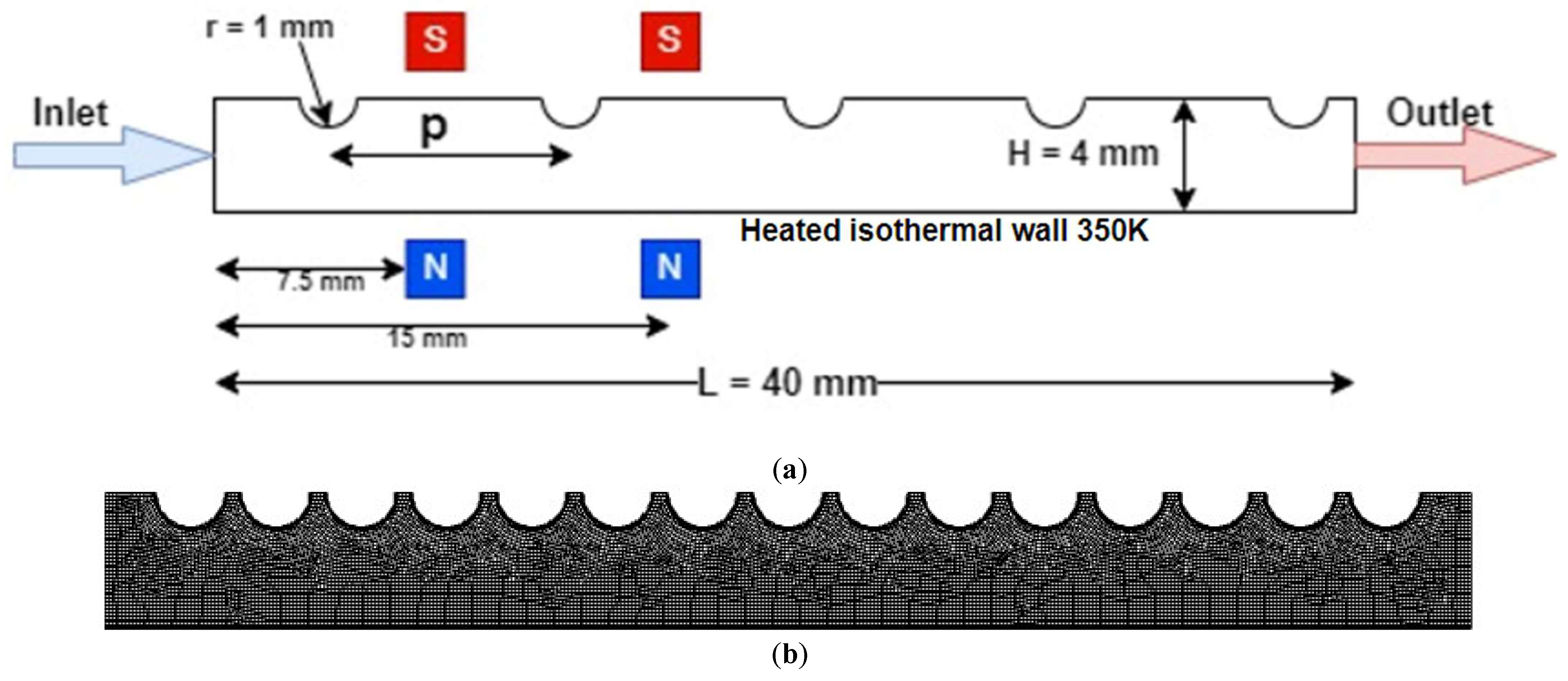
2.1. Geometry and Grid Generation

A two-dimensional mini channel, shown in Figure 1a, consisted of two parallel flat plates, each of 40 mm length with 4 mm spacing. The top surface of the channel was maintained adiabatic, while the bottom surface was kept in isothermal conditions. The 2 Vol% Fe3O4/water ferrofluid was considered as the coolant and fluid flown into the channel at a uniform inlet velocity and temperature. A rectangular grid, as shown in Figure 1b, was chosen for the flow domain, having 80 computational nodes in vertical direction and 320 nodes in the horizontal direction, with bias of factor 4 near the hot wall to effectively capture the velocity and thermal gradient. The magnets were placed at two different locations x = 7.5 mm and 15.0 mm, and the magnetic force acted in an upwards direction, as shown in Figure 1, and three different dimple pitches were also studied (2.5 mm, 5.0 mm, and 10.0 mm).

2.2. Governing Equations

Assuming a two-dimensional, steady state, homogenous and laminar flow, the continuity, momentum and energy equations are described below. The equations governing the flow are given by:
  • Continuity equation:
. ρ V = 0
  • Momentum equations:
. ρ V V = P + . τ i j + F k
where τ i j represents the shear stress vector and is given by:
τ i j = μ v i x j + v j x i 2 3 μ δ i j v i x i
  • Energy equation:
. ρ V C p T = . k T
The momentum equation includes the magnetic volume force, F k , to incorporate the effect of the magnetic field on the nanofluid, which is described below in detail.
The Maxwell equation was used to calculate the magnetic flux density ( B ), as follows:
B = μ 0   M + H
where M is the magnetization; H is the magnetic field intensity; and μ 0 is the permeability of the medium.
The magnetization vector M is assumed to be aligned with the magnetic field intensity as:
M = χ m   H
where χ m is the magnetic susceptibility and is dependent on temperature.
The magnetic volume force is obtained from:
F k = 1 2 μ 0   χ m 1 + χ m H . H + μ 0   χ m H H . χ m
Here, the first term in the right-hand side of the above equation (Equation (7)) is due to a non-uniform magnetic field. Meanwhile, the second term that becomes dominant is a spatial gradient that exists in the magnetic susceptibility. In the present study, the external magnetic force created by the four magnets is uniform, hence the first term is zero. As susceptibility varies with the temperature, the second term varies along the flow domain, and hence the magnetic volume force exhibits a normal, uniform value to the flow direction in the mini channel.
In the present study, the different configurations were tested to find the heat transfer from the bottom surface. These configurations are one source at the front (x = 7.5 mm) and the other source at x = 15 mm (as shown in Figure 1a). The configurations are tested with a different set of Re and magnetic field strengths. Each magnet behaves as a virtual baffle whose height depends on the strength of the magnetic field. By increasing the number of magnets, the turbulence increases, hence the heat transfer is also enhanced. However, due to the formation of vortices and eddies, the pressure drop also increases with it. So, we need to find the optimum case for it.

2.3. Boundary Conditions

The boundary condition of the computational domain is very important. The bottom wall of the two-dimensional mini channel was isothermally heated at 350 K, while the top surface of the channel was kept insulated. No-slip velocity and temperature jump condition were imposed at the channel walls. A uniform velocity and a temperature of 293 K were maintained at the channel inlet. The atmospheric pressure was maintained at the outlet of the channel. The physical and magnetic properties of the ferrofluid used as a working fluid for the current study are shown in Table 1.
It is important to take the properties of the nanofluid as a function of temperature and nanoparticle concentration. Assuming that the concentration of the nanoparticles is uniform throughout the domain, the effective physical properties of the nanofluid can be calculated as follows [16,45,46]:
ρ n f = 1 φ ρ f + φ ρ n p
ρ C p n f = 1 φ ρ C p f + φ ρ C p n p
μ n f = μ f 1 + 2.5 φ
k n f = k s t a t i c + k b r o w n i a n
where:
k s t a t i c = k f k n p + 2 k f 2 φ k f k n p k n p + 2 k f + φ k f k n p
k b r o w n i a n = 5 × 10 4 β φ ρ f C p , f k T ρ n f D n p g φ , T    
where k is the Boltzmann constant; φ is the nanopraticle concentration; β is the fraction of liquid volume; and g is the modelling function given by:
g φ , T = 6.04 φ + 0.4705 T + 1722.3 φ 134.63
In addition, the physical properties of the base fluid, water in the present study, are assumed to be a function of temperature for better accuracy. They are given by:
ρ f = 2446 20.674 T + 0.11576 T 2 3.12895 × 10 4 T 3 + 4.0505 × 10 7 T 4 2.0546 × 10 10 T 5
μ f = 2.414 × 10 5 × 10 247 T 140
k f = 1.13 + 9.71 × 10 3 T 1.31 × 10 5 T 2

2.4. Thermo-Hydraulic Parameters

The Nusselt Number (Nu) represents the ratio of convective to conductive heat transfer at a boundary in fluid [16]. It is given by:
N u = C o n v e c t i v e   h e a t   t r a n s f e r C o n d u c t i v e   h e a t   t r a n s f e r = h K D = h D K  
where k is the thermal conductivity of fluid; D is the hydraulic diameter of the channel; and h is the local convective heat transfer coefficient given by:
h = q T w T b

2.5. CFD Solver Settings

The finite volume-based commercial computational fluid dynamics (CFD) solver, ANSYS-Fluent, was used to numerically simulate the current problem. The present study investigated the flow at a very low Res, namely, Re = 150, 170, 190, and 210 calculated based on the channel width. Hence, the laminar viscous model is used with pressure-velocity coupling. A second-order upwind discretization scheme was used for discretizing the momentum equations and the QUICK scheme was used for the energy equation [47].

3. Grid Independence Test and Validation

To ensure that the results of the numerical analysis were independent of the density of the mesh, the non-dimensional velocity profile was obtained at the outlet of the channel at Re 170 and B = 0 G for the three different grids. The velocity profile obtained was almost the same for the three grids, as shown in Figure 2a. So as to maintain a balance between accuracy and the time required for computation, a mesh with 80 × 320 divisions was selected for study.
The present study is also validated with the numerical and experimental investigation completed by Bezaatpour et al. [16] and Ashjaee et al. [48] for the heating channel with two magnet sources at the front, i.e., 7.5 mm and 15 mm. The results obtained are within the error 5% limits as compared to the validated work. The validation is shown in Figure 2b.

4. Results and Discussion

The numerical investigations in ANSYS Fluent were carried out for all of the cases as mentioned above, and the Nusselt number and pressure drop were obtained and reported in this section.

4.1. Variation of Nusselt Number with Re

Figure 3a–c shows the variation of the heat transfer with the Re for the dimple turbulator pitches of 2.5 mm, 5 mm and 10 mm, respectively, with one source placed at x = 15 mm. For all three cases, the Nusselt number increases with the increase in Re and the strength of the magnetic field. A similar trend is observed when two sources are placed at x = 7.5 mm and 15 mm. Figure 3d–f shows the variation of heat transfer with Re for a dimple turbulator pitch of 2.5 mm, 5 mm, and 10 mm, respectively, with two sources placed at x = 7.5 mm and 15 mm. In this case, the highest Nusselt number is obtained for 2000 G, followed by 1500 G, 1200 G, and 0 G.
It is because the high magnetic field creates a higher turbulence vortex in the fluid domain. The magnetic field provides an upwards force and creates a flow separation, leading to the formation of a vortex. The higher the strength of the magnetic field, the higher will be the size of the vortex, and the higher will be the flow mixing, resulting in a higher heat transfer. For one source at x = 15 mm, Figure 4a,c,e shows the velocity contours for a dimple turbulator pitch of 2.5 mm, 5 mm, and 10 mm, respectively. For all the three cases, as the strength of the magnetic field increases, the vortex size increases, leading to a higher Nusselt number. Similarly, Figure 4b,d,f shows the velocity contours for a dimple turbulator pitch of 2.5 mm, 5 mm, and 10 mm, respectively, for two sources at x = 7.5 mm and 15 mm. In this case as well, the size of the vortex increases with the strength of the magnetic field. The increment in the Nusselt number is an average of 20% at 2000 G, 8% at 1500 G, while only 2–3% at 1200 G as compared to the flow without a magnetic field for all the three dimple turbulator pitch geometry. It should also be noted that the projections in the upper wall are preventing the merging of the two vortexes in Figure 4d,f. Usually at higher magnetic fields, the two vortexes merge to form a bigger vortex, increasing the heat transfer.

4.2. Variation of Nusselt Number along the Length of the Channel

Figure 5a–c shows the variation of Nusselt number along the length of the channel at different magnetic fields, for a dimple turbulator pitch of 2.5 mm, 5 mm, and 10 mm. It should be noted that the number of spikes in each line represents the vortex in formation in the domain. Hence, in each of the three figures (Figure 5a–c), no spike is there at 0 G, one spike is there when one source is placed at x = 15 mm, and two spikes are there when the two sources are placed at x = 7.5 mm and 15 mm. The formation of the spike can be explained by understanding the flow pattern. When the magnetic field is applied, the flow is directed upwards creating a flow separation and the first vortex at the bottom wall. Due to the formation of the vortex, the flow cross-sectional area decreases, hence increasing the flow velocity above the vortex, and the flow strikes the upper wall, due to which its direction is directed downwards just after the second half of the first vortex and this causes the flow to strike the bottom wall with a high velocity. Hence, the thermal boundary layer is very thin just after the vortex and the zone of very high temperature gradient at the heated wall, which causes the spike. This also explains that the number of spikes denote the number of vortexes in the flow domain.
Figure 5d,e shows the variation in the Nusselt number along the channel length at a constant magnetic field for all of the three dimple turbulator pitches (2.5, 5.0, 10.0 mm) when one source and two sources are used, respectively. For both of the figures, the height of the spike decreases with the decrease in the pitch of the projections. This is because, as the pitch of the projections decreases, the space between them decreases, which increases the average velocity of the flow in the domain, which decreases the effect of the magnetic field. In addition, the size of the vortex decreases due to less space being available in the upwards direction, see Figure 4a–f. With a large vortex, the flow strikes the bottom wall with a higher velocity, hence increasing the temperature gradient causing a higher spike. Hence, the height of the spike is greatest for a pitch of 10 mm, followed by 5 mm, and 2.5 mm.

4.3. Variation of the Pressure Drop across the Channel with Re

Figure 6a–c shows the variation in the pressure drop across the channel with the Re at different magnetic fields for a dimple turbulator pitch of 2.5 mm, 5 mm, and 10 mm, respectively. Interestingly, the pressure drop is decreasing with the increase in the magnetic field. It is opposite to the initial hypothesis, because the higher magnetic field creates a bigger vortex and higher turbulence, and the pressure drop must be higher.
However, due to the flow separation caused by the upward directed magnetic field, there is a decrease in the frictional pressure drop. At the lower magnetic fields, the decrease in the frictional pressure drop dominates over the increase in the pressure drop due to turbulence. This is observed in all of the three tested geometries with the different pitches. However, these results are not expected at very high magnetic fields because the very high turbulence will dominate over the decrease in the pressure drop. This similar trend is observed when two sources are placed at x = 7.5 mm and 15 mm, see Figure 6d–f. In Figure 6d–f as well, the pressure drop is least when the magnetic field of 2000 G is applied, followed by 1500 G, 1200 G, and the maximum for the flow without magnetic field.

4.4. Comparison

Figure 7a,b shows the comparison of the Nusselt number for all of the three dimple turbulator pitches of a one source front and a two source front, respectively, at G = 2000. For one source at x = 15 mm, see Figure 7a, the Nusselt number is maximum for a pitch of 5 mm, followed by 2.5 mm and 10 mm. It is because the average velocity in the domain is highest for the least pitch, however due to the increase in velocity, hence inertia, the effect of the magnetic field is decreased. Hence the geometry with highest effective velocity (inertia) will have least magnetic effect, and vice versa. At a dimple turbulator pitch of 5 mm, the effect of increase in the heat transfer due to higher velocity and magnetic field is added, hence the heat transfer is maximum in it. For a dimple turbulator pitch of 2.5 mm, commutative heat transfer due to higher velocity and lesser the magnetic field effect dominates the increase in the heat transfer due to lower velocity at 10 mm. For lower Re, Re 150, the heat transfer is almost same for both a 10 mm pitch and 2.5 mm pitch, because of equal effect of increase in the heat transfer due to magnetic field and higher velocity. A little different result is observed when two sources are applied at x = 7.5 mm and 15 mm at G = 2000, refer Figure 7b. Nusselt number is highest for 5 mm again across entire variable range, however for lower Re (at Re 150 and 170), the 10 mm pitch dominates over the 2.5 mm pitch due to higher magnetic effect and at higher Re (at Re 190 and 210), the 2.5 pitch dominates over the 10 mm pitch due to higher velocity effect. Hence, for cases of less turbulence, the 2.5 mm pitch dominates over the 10 mm and vice versa in the case of higher turbulence. A 5 mm pitch remains the highest performing in heat transfer across all of the cases.
In addition, Figure 7c,d shows the comparison of the pressure drop between the three dimple pitches for a one source front and a two source front, respectively, at G = 2000. For both of the cases, the pressure drop increases with the decreases in the pitch. It is because of the higher velocity in the less pitched geometry. In addition, Figure 7e shows the comparison of the heat transfer between a one source front and two sources at the front for all of the pitches at G = 2000. It is clear that the two sources at the front have a higher heat transfer rate as compared to one source at the front, due to higher turbulence caused by the two vortexes. In addition, Figure 7f shows at constant G = 2000 that the pressure drop is lesser for two sources at the front as compared to one source at the front, due to the dominance of the decrease in the frictional pressure drop as compared to the increase in the pressure drop due to turbulence.

5. Conclusions

The influence of the magnetic baffle and the dimple turbulator on the heat transfer and pressure drop is studied numerically. A magnetic field is used along with a dimple turbulator to create the swirl flow in the 2D domain. The cases were analyzed numerically and the heat transfer and pressure drop results were obtained for all of the Re (Re 150–201) at different magnetic field intensities (G = 0, 1200, 1500, 2000) and different dimple pitches (p = 2.5, 5.0, 10.0 mm). The following conclusions can be made from the observations obtained from the study:
  • The magnetic field is used to create a virtual baffle along with artificial roughness (dimple turbulator) which helps to create turbulence and flow mixing regions, hence increasing the heat transfer;
  • The height of the ‘baffle’ is to be varied by varying the magnetic field. Higher Nusselt numbers were obtained when the magnet was placed more downstream as compared to upstream;
  • The pressure drop due to the virtual baffle is less than the physical baffle, because of the absence of a horizontal backwards force in the case of the magnetic field;
  • There is an increase of 3.53%, 10.77%, and 25.39% in the Nusselt numbers when the magnetic fields of 1200 G, 1500 G, and 2000 G, respectively, are applied at x = 15 mm, as compared to the flow without a magnetic field when the pitch = 10 mm;
  • When two sources are placed at x = 7.5 mm and 15 mm, there is an increase of 4.52%, 13.93%, and 33.08% in the Nusselt numbers when the magnetic fields of 1200 G, 1500 G and 2000 G are applied and when the pitch = 10 mm.

Author Contributions

Conceptualization, B.S. and S.B.; methodology, B.S. and S.B.; software, S.B.; validation, B.S. and S.B.; formal analysis, N.H.; investigation, F.H.; resources, S.S.K.R.; data curation, S.B.; writing—original draft preparation, B.S.; writing—review and editing, M.W.A. and E.Y.; visualization, T.A.; supervision, M.A.N.; project administration, B.S.; funding acquisition, B.S. All authors have read and agreed to the published version of the manuscript.

Funding

This work was funded by the Deanship of Scientific Research, Vice Presidency for Graduate Studies and Scientific Research, King Faisal University, Saudi Arabia (Project No. GRANT331). The authors also acknowledge the financial support received for the research project entitled “Performance Improvement of Solar Thermal Systems using Magnetic Nanofluids” funded by the Department of Science and Technology (DST), Govt. of India under India-South Africa Joint Science and Technology Research Collaboration vide Sanction no.: DST/INT/South Africa/P-08/2021 dtd. 16 September 2021.

Institutional Review Board Statement

Not applicable.

Informed Consent Statement

Not applicable.

Data Availability Statement

Not applicable.

Acknowledgments

This work was supported by the Deanship of Scientific Research, Vice Presidency for Graduate Studies and Scientific Research, King Faisal University, Saudi Arabia (Project No. GRANT331). The authors also acknowledge the financial support received for the research project entitled “Performance Improvement of Solar Thermal Systems using Magnetic Nanofluids” funded by the Department of Science and Technology (DST), Govt. of India under India-South Africa Joint Science and Technology Research Collaboration vide Sanction no.: DST/INT/South Africa/P-08/2021 dtd. 16 September 2021.

Conflicts of Interest

The authors declare they have no conflict of interest for this submission.

Nomenclature

Symbols
BMagnetic field intensity (Gauss)
CpSpecific heat (J/kg/K)
DHydraulic diameter (m)
FkMagnetic body force (N)
HChannel height (m), magnetic field intensity
hHeat transfer coefficient (W/m2 K)
kBoltzmann constant
KThermal conductivity (W/m−1 K−1)
L2D channel length (m)
MMagnetization (A m−1)
NuNusselt number
PPressure drop (Pa)
qHeat flux (W/m2)
ReReynolds number
TTemperature (K)
uHorizontal velocity (m/s)
vVertical velocity (m/s)
VVelocity (m/s)
x, yDirections
Greek Symbols
ϕVolume fraction
χmMagnetic susceptibility
χoDifferential magnetic Susceptibility (0.06)
ρDensity (kg/m3)
μDynamic viscosity (N s/m2)
μ0Permeability of free space (4π × 10−7 N/A2)
βFraction of the liquid volume (k−1)
τWall shear stress (Pa)
δThickness (m)
Subscripts
bBulk
fFluid
nfNanofluid
npNanoparticle
inInlet
wWall

References

  1. Bhattacharyya, S.; Vishwakarma, D.K.; Srinivasan, A.; Soni, M.K.; Goel, V.; Sharifpur, M.; Ahmadi, M.H.; Issakhov, A.; Meyer, J. Thermal performance enhancement in heat exchangers using active and passive techniques: A detailed review. J. Therm. Anal. Calorim. 2022, 147, 9229–9281. [Google Scholar] [CrossRef]
  2. Bhattacharyya, S.; Vishwakarma, D.K.; Chakraborty, S.; Roy, R.; Issakhov, A.; Sharifpur, M. Turbulent flow heat transfer through a circular tube with novel hybrid grooved tape inserts: Thermohydraulic analysis and prediction by applying machine learning model. Sustainability 2021, 13, 3068. [Google Scholar] [CrossRef]
  3. Bhattacharyya, S.; Vishwakarma, D.K.; Goel, V.; Chamoli, S.; Issakhov, A.; Meyer, J.P. Thermodynamics and heat transfer study of a circular tube embedded with novel perforated angular-cut alternate segmental baffles. J. Therm. Anal. Calorim. 2021, 145, 1445–1465. [Google Scholar] [CrossRef]
  4. Bhattacharyya, S.; Vishwakarma, D.K.; Soni, M.K. Heat transfer and pressure drop in transitional flow: A short review. In Proceedings of the 3rd International Conference on Advances in Mechanical Engineering and its Interdisciplinary Areas (ICAMEI 2021), Kolaghat, India, 5–7 January 2021; Volume 1080, p. 012050. [Google Scholar] [CrossRef]
  5. Bhattacharyya, S.; Vishwakarma, D.K.; Roy, S.; Biswas, R.; Ardekani, M.M. Applications of heat transfer enhancement techniques: A state-of-the-art review. In Inverse Heat Conduction Heat Exchange; IntechOpen: London, UK, 2020. [Google Scholar] [CrossRef]
  6. Bhattacharyya, S.; Vishwakarma, D.K.; Roy, S.; Dey, K.; Benim, A.C.; Bennacer, R.; Paul, A.R.; Huan, Z. Computational investigation on heat transfer augmentation of a circular tube with novel hybrid ribs. E3S Web Conf. 2021, 321, 04012. [Google Scholar] [CrossRef]
  7. Kumar, A.; Dey, K.; Bhattacharyya, S.; Paul, A.R.; Benim, A.C.; Vishwakarma, D.K.; Huan, Z. Augmented thermal performance in a non-uniform heat flux circular tube with twisted tape insert using hybrid nanofluid. E3S Web Conf. 2021, 321, 04009. [Google Scholar] [CrossRef]
  8. Souayeh, B.; Bhattacharyya, S.; Hdhiri, N.; Alam, M.W. Heat and fluid flow analysis and ann-based prediction of a novel spring corrugated tape. Sustainability 2021, 13, 3023. [Google Scholar] [CrossRef]
  9. Ibrahim, M.; Saeed, T.; Bani, F.R.; Sedeh, S.N.; Chu, Y.M.; Toghraie, D. Two-phase analysis of heat transfer and entropy generation of water-based magnetite nanofluid flow in a circular microtube with twisted porous blocks under a uniform magnetic field. Powder Technol. 2021, 384, 522–541. [Google Scholar] [CrossRef]
  10. Lee, A.; Jeon, Y.; Chinnasamy, V.; Cho, H. Investigation of forced convective heat transfer with magnetic field effect on water/ethylene glycol-cobalt zinc ferrite nanofluid. Int. Commun. Heat Mass Transf. 2021, 128, 105647. [Google Scholar] [CrossRef]
  11. Mehryan, S.A.M.; Izadi, M.; Namazian, Z.; Chamkha, A.J. Natural convection of multi-walled carbon nanotube–Fe3O4/water magnetic hybrid nanofluid flowing in porous medium considering the impacts of magnetic field-dependent viscosity. J. Therm. Anal. Calorim. 2019, 138, 1541–1555. [Google Scholar] [CrossRef]
  12. Niknejadi, M.; Afrand, M.; Karimipour, A.; Shahsavar, A.; Isfahani, A.H.M. An experimental study on the cooling efficiency of magnetite–water nanofluid in a twisted tube exposed to a rotating magnetic field. J. Therm. Anal. Calorim. 2021, 146, 1893–1909. [Google Scholar] [CrossRef]
  13. Rawa, M.J.H.; Abu-Hamdeh, N.H.; Golmohammadzadeh, A.; Goldanlou, A.S. An investigation on effects of blade angle and magnetic field on flow and heat transfer of non-Newtonian nanofluids: A numerical simulation. Int. Commun. Heat Mass Transf. 2021, 120, 105074. [Google Scholar] [CrossRef]
  14. Alghamdi, M.; Wakif, A.; Thumma, T.; Khan, U.; Baleanu, D.; Rasool, G. Significance of variability in magnetic field strength and heat source on the radiative-convective motion of sodium alginate-based nanofluid within a Darcy-Brinkman porous structure bounded vertically by an irregular slender surface. Case Stud. Therm. Eng. 2021, 28, 101428. [Google Scholar] [CrossRef]
  15. Biswas, N.; Mondal, M.K.; Mandal, D.K.; Manna, N.K.; Subba, R.; Gorla, R.; Chamkha, A.J. A narrative loom of hybrid nanofluid-filled wavy walled tilted porous enclosure imposing a partially active magnetic field. Int. J. Mech. Sci. 2021, 271, 107028. [Google Scholar] [CrossRef]
  16. Bezaatpour, M.; Goharkhah, M. A magnetic vortex generator for simultaneous heat transfer enhancement and pressure drop reduction in a mini channel. Heat Transf. Asian Res. 2020, 49, 1192–1213. [Google Scholar] [CrossRef]
  17. Bezaatpour, M.; Goharkhah, M. Effect of magnetic field on the hydrodynamic and heat transfer of magnetite ferrofluid flow in a porous fin heat sink. J. Magn. Magn. Mater. 2019, 476, 506–515. [Google Scholar] [CrossRef]
  18. Karimi, A.; Afghahi, S.S.S.; Shariatmadar, H.; Ashjaee, M. Experimental investigation on thermal conductivity of MFe2O4 (M = Fe and Co) magnetic nanofluids under influence of magnetic field. Thermochim. Acta 2014, 598, 59–67. [Google Scholar] [CrossRef]
  19. Qi, C.; Tang, J.; Fan, F.; Yan, Y. Effects of magnetic field on thermo-hydraulic behaviors of magnetic nanofluids in CPU cooling system. Appl. Therm. Eng. 2020, 179, 115717. [Google Scholar] [CrossRef]
  20. Mousavi, S.V.; Sheikholeslami, M.; Goriji Bandpy, M.; Gerdroodbary, M.B. The Influence of magnetic field on heat transfer of magnetic nanofluid in a sinusoidal double pipe heat exchanger. Chem. Eng. Res. Des. 2016, 113, 112–124. [Google Scholar] [CrossRef]
  21. Zhang, X.; Zhang, Y. Experimental study on enhanced heat transfer and flow performance of magnetic nanofluids under alternating magnetic field. Int. J. Therm. Sci. 2021, 164, 106897. [Google Scholar] [CrossRef]
  22. Sundar, L.S.; Naik, M.T.; Sharma, K.V.; Singh, M.K.; Reddy, T.C.S. Experimental investigation of forced convection heat transfer and friction factor in a tube with Fe3O4 magnetic nanofluid. Exp. Therm. Fluid Sci. 2012, 37, 65–71. [Google Scholar] [CrossRef]
  23. Yu, W.; Xie, H.; Chen, L.; Li, Y. Enhancement of thermal conductivity of kerosene-based Fe3O4 nanofluids prepared via phase-transfer method. Colloids Surf. A Physicochem. Eng. Asp. 2010, 355, 109–113. [Google Scholar] [CrossRef]
  24. Wen, D.; Ding, Y. Experimental investigation into convective heat transfer of nanofluids at the entrance region under laminar flow conditions. Int. J. Heat Mass Transf. 2004, 47, 5181–5188. [Google Scholar] [CrossRef]
  25. Goharkhah, M.; Ashjaee, M.; Shahabadi, M. Experimental investigation on convective heat transfer and hydrodynamic characteristics of magnetite nanofluid under the influence of an alternating magnetic field. Int. J. Therm. Sci. 2016, 99, 113–124. [Google Scholar] [CrossRef]
  26. Azizian, R.; Doroodchi, E.; McKrell, T.; Buongiorno, J.; Hu, L.W.; Moghtaderi, B. Effect of magnetic field on laminar convective heat transfer of magnetite nanofluids. Int. J. Heat Mass Transf. 2014, 68, 94–109. [Google Scholar] [CrossRef]
  27. Li, Q.; Xuan, Y. Experimental investigation on heat transfer characteristics of magnetic fluid flow around a fine wire under the influence of an external magnetic field. Exp. Therm. Fluid Sci. 2009, 33, 591–596. [Google Scholar] [CrossRef]
  28. Safaei, M.R.; Abdelghany Elkotb, M.; Alsharif, A.M.; Mansir, I.B.; Alamri, S.; Tirth, V.; Goodarzi, M. An innovative design of a high strength and low weight sudden micro expansion by considering a nanofluid: Electronic cooling application. Case Stud. Therm. Eng. 2021, 28, 101637. [Google Scholar] [CrossRef]
  29. Alrashed, A.A.A.A.; Akbari, O.A.; Heydari, A.; Toghraie, D.; Zarringhalam, M.; Shabani, G.A.S.; Seifi, A.R.; Goodarzi, M. The numerical modeling of water/FMWCNT nanofluid flow and heat transfer in a backward-facing contracting channel. Phys. B Condens. Matter 2018, 537, 176–183. [Google Scholar] [CrossRef]
  30. Togun, H.; Safaei, M.R.; Sadri, R.; Kazi, S.N.; Badarudin, A.; Hooman, K.; Sadeghinezhad, E. Numerical simulation of laminar to turbulent nanofluid flow and heat transfer over a backward-facing step. Appl. Math. Comput. 2014, 239, 153–170. [Google Scholar] [CrossRef]
  31. Safaei, M.R.; Togun, H.; Vafai, K.; Kazi, S.N.; Badarudin, A. Investigation of heat transfer enhancement in a forward-facing contracting channel using FMWCNT nanofluids. Numer. Heat Transf. Part A Appl. 2014, 66, 1321–1340. [Google Scholar] [CrossRef]
  32. Bhattacharyya, S.; Chattopadhyay, H.; Haldar, A. Design of twisted tape turbulator at different entrance angle for heat transfer enhancement in a solar heater. Beni-Suef Univ. J. Basic Appl. Sci. 2018, 7, 118–126. [Google Scholar] [CrossRef]
  33. Bhattacharyya, S.; Chattopadhyay, H.; Biswas, R.; Ewim, D.R.E.; Huan, Z. Influence of inlet turbulence intensity on transport phenomenon of modified diamond cylinder: A numerical study. Arab. J. Sci. Eng. 2020, 45, 1051–1058. [Google Scholar] [CrossRef]
  34. Jin, D.; Quan, S.; Zuo, J.; Xu, S. Numerical investigation of heat transfer enhancement in a solar air heater roughened by multiple V-shaped ribs. Renew. Energy 2019, 134, 78–88. [Google Scholar] [CrossRef]
  35. Mohammed, H.A.; Abbas, A.K.; Sheriff, J.M. Influence of geometrical parameters and forced convective heat transfer in transversely corrugated circular tubes. Int. Commun. Heat Mass Transf. 2013, 44, 116–126. [Google Scholar] [CrossRef]
  36. Effatpanah, S.K.; Ahmadi, M.H.; Aungkulanon, P.; Maleki, A.; Sadeghzadeh, M.; Sharifpur, M.; Chen, L. Comparative analysis of five widely-used multi-criteria decision-making methods to evaluate clean energy technologies: A case study. Sustainability 2022, 14, 1403. [Google Scholar] [CrossRef]
  37. Ahmadi, M.H.; Kumar, R.; Assad, M.E.H.; Ngo, P.T.T. Applications of Machine Learning Methods in Modeling Various Types of Heat Pipes: A Review. J. Therm. Anal. Calorim. 2021, 146, 2333–2341. [Google Scholar] [CrossRef]
  38. Jagtap, H.P.; Bewoor, A.K.; Kumar, R.; Ahmadi, M.H.; El Haj Assad, M.; Sharifpur, M. RAM Analysis and availability optimization of thermal power plant water circulation system using PSO. Energy Rep. 2021, 7, 1133–1153. [Google Scholar] [CrossRef]
  39. Sabbagh, O.; Fanaei, M.A.; Arjomand, A.; Hossein Ahmadi, M. Multi-objective optimization assessment of a new integrated scheme for co-production of natural gas liquids and liquefied natural gas. Sustain. Energy Technol. Assess. 2021, 47, 101493. [Google Scholar] [CrossRef]
  40. Zolghadri, A.; Maddah, H.; Ahmadi, M.H.; Sharifpur, M. Predicting parameters of heat transfer in a shell and tube heat exchanger using aluminum oxide nanofluid with artificial neural network (Ann) and self-organizing map (Som). Sustainability 2021, 13, 8824. [Google Scholar] [CrossRef]
  41. Lohakare, P.; Bewoor, A.; Kumar, R.; Said, N.M.; Sharifpur, M. Benchmark using multi criteria decision making (MCDM) technique to optimally select piston material. Eng. Anal. Bound. Elem. 2022, 142, 52–60. [Google Scholar] [CrossRef]
  42. Kumar, R.; Nadda, R.; Kumar, S.; Razak, A.; Sharifpur, M.; Aybar, H.S.; Ahamed Saleel, C.; Afzal, A. Influence of artificial roughness parametric variation on thermal performance of solar thermal collector: An experimental study, response surface analysis and ANN modelling. Sustain. Energy Technol. Assess. 2022, 52, 102047. [Google Scholar] [CrossRef]
  43. Sharma, J.; Soni, S.; Paliwal, P.; Saboor, S.; Chaurasiya, P.K.; Sharifpur, M.; Khalilpoor, N.; Afzal, A. A novel long term solar photovoltaic power forecasting approach using LSTM with Nadam optimizer: A case study of India. Energy Sci. Eng. 2022, 10, 2909–2929. [Google Scholar] [CrossRef]
  44. Melaibari, A.A.; Khetib, Y.; Alanazi, A.K.; Sajadi, S.M.; Sharifpur, M.; Cheraghian, G. Applying artificial neural network and response surface method to forecast the rheological behavior of hybrid nano-antifreeze containing graphene oxide and copper oxide nanomaterials. Sustainability 2021, 13, 11505. [Google Scholar] [CrossRef]
  45. KAbu-Nab, A.; Selima, E.S.; Morad, A.M. Theoretical investigation of a single vapor bubble during Al2O3/H2O nanofluids in power-law fluid affected by a variable surface tension. Phys. Scr. 2021, 96, 035222. [Google Scholar] [CrossRef]
  46. Morad, A.M.; Selima, E.S.; Abu-Nab, A.K. Thermophysical bubble dynamics in N-dimensional Al2O3/H2O nanofluid between two-phase turbulent flow. Case Stud. Therm. Eng. 2021, 28, 101527. [Google Scholar] [CrossRef]
  47. Bhattacharyya, S.; Abraham, J.P.; Cheng, L.; Gorman, J. Introductory chapter: A brief history of and introduction to computational fluid dynamics. In Computational Fluid Dynamics; IntechOpen: London, UK, 2021. [Google Scholar] [CrossRef]
  48. Ashjaee, M.; Goharkhah, M.; Khadem, L.A.; Ahmadi, R. Effect of magnetic field on the forced convection heat transfer and pressure drop of a magnetic nanofluid in a miniature heat sink. Heat Mass Transf. 2015, 51, 953–964. [Google Scholar] [CrossRef]
Figure 1. (a) Computational domain; and (b) Meshing of the computational domain.
Sustainability 14 10419 g001
Figure 2. (a) Grid Independence test, and (b) Validation of numerical results at Re 170 with B = 0 G and 1200 G (Mojtaba et al., 2020 [16]); (c) Validation with experimental study at Re 170 with B = 0 G and 1200 G (Ashjee et al., 2015 [48]).
Sustainability 14 10419 g002aSustainability 14 10419 g002b
Figure 3. (a) Variation of Nusselt Number with Re for one source at x = 15 mm and pitch = 2.5 mm; (b) Variation of Nusselt Number with Re for one source at x = 15 mm and pitch = 5 mm; (c) Variation of Nusselt Number with Re for one source at x = 15 mm and pitch = 10 mm; (d) Variation of Nusselt Number with Re for two sources at x = 7.5 mm and 15 mm and pitch = 2.5 mm; (e) Variation of Nusselt Number with Re for two sources at x = 7.5 mm and 15 mm and pitch = 5 mm; and (f) Variation of Nusselt Number with Re for two sources at x = 7.5 mm and 15 mm and pitch = 10 mm.
Sustainability 14 10419 g003aSustainability 14 10419 g003bSustainability 14 10419 g003c
Figure 4. (a) Velocity contours at one source at x = 15 mm and pitch = 2.5 mm and Re 190; (b) Velocity contours at two sources at x = 7.5 mm and 15 mm and pitch = 2.5 mm and Re 190; (c) Velocity contours at one source at x = 15 mm and pitch = 5 mm and Re 190; (d) Velocity contours at one source at x = 7.5 mm and 15 mm and pitch = 5 mm and Re 190; (e) Velocity contours at one source at x = 15 mm and pitch = 10 mm and Re 190; and (f) Velocity contours at two sources at x = 15 mm and pitch = 10 mm and Re 190.
Sustainability 14 10419 g004aSustainability 14 10419 g004bSustainability 14 10419 g004cSustainability 14 10419 g004d
Figure 5. (a) Variation of Nusselt number along the length of the channel for pitch = 2.5 mm and B = 2000 G; (b) Variation of Nusselt number along the length of the channel for pitch = 5 mm and B = 2000 G; (c) Variation of Nusselt number along the length of the channel for pitch = 10 mm and B = 2000 G; (d) Variation of Nusselt number along the length of the channel for one source at x = 15 mm and B = 2000 G; and (e) Variation of Nusselt number along the length of the channel for two sources at x = 7.5 mm and 15 mm and B = 2000 G.
Sustainability 14 10419 g005aSustainability 14 10419 g005bSustainability 14 10419 g005c
Figure 6. (a) Variation of Pressure Drop for one source at x = 15 mm and pitch = 2.5 mm; (b) Variation of Pressure Drop for one source at x = 15 mm and pitch = 5 mm; (c) Variation of Pressure Drop for one source at x = 15 mm and pitch = 10 mm; (d) Variation of Pressure Drop for two sources at x = 7.5 mm and 15 mm and pitch = 2.5 mm; (e) Variation of Pressure Drop for two sources at x = 7.5 mm and 15 mm and pitch = 5 mm; and (f) Variation of Pressure Drop for two source at x = 7.5 mm and 15 mm and pitch = 10 mm.
Sustainability 14 10419 g006aSustainability 14 10419 g006bSustainability 14 10419 g006c
Figure 7. (a) Comparison of Nusselt number for different pitches at G = 2000 and one source at x = 15 mm; (b) Comparison of Nusselt number for different pitches at G = 2000 and two sources at x = 7.5 mm and 15 mm; (c) Comparison of Pressure Drop for different pitches at G = 2000 and one source at x = 15 mm; (d) Comparison of Nusselt number for different pitches at G = 2000 and two sources at x = 7.5 mm and 15 mm; (e) Comparison of Nusselt number between one source at x = 15 mm and two sources at x = 7.5 mm and 15 mm at G = 2000; and (f) Comparison of Pressure Drop for different pitches at G = 2000 and two sources at x = 7.5 mm and 15 mm.
Sustainability 14 10419 g007aSustainability 14 10419 g007bSustainability 14 10419 g007cSustainability 14 10419 g007d
Table 1. Physical properties of Fe3O4 nanoparticles.
PropertyValue
Diameter20 nm
Density 4950   kg / m 3
Thermal Conductivity7 W/m·K
Specific Heat640 J/Kg·K
Publisher’s Note: MDPI stays neutral with regard to jurisdictional claims in published maps and institutional affiliations.

