Article

Experimental Investigation on Bending Behavior of Innovative Poplar LVL Floor Diaphragms

College of Architectural Science and Engineering, Yangzhou University, Yangzhou 225127, China
*
Author to whom correspondence should be addressed.
Sustainability 2022, 14(17), 10481; https://doi.org/10.3390/su141710481
Submission received: 11 July 2022 / Revised: 11 August 2022 / Accepted: 20 August 2022 / Published: 23 August 2022
(This article belongs to the Special Issue Sustainable Development of Construction Engineering)

Abstract

:
Poplar laminated veneer lumber (poplar LVL) is made of fast-growing poplar veneer and structural adhesive, which owns the advantages of sustainability and stable quality. Here an innovative poplar LVL floor diaphragm is presented, mainly made up of orthogonal rib beams fitted together using L-shape steel connectors. The paper mainly deals with an experimental study on the bending behavior of the floor under transverse uniform load. Full-scale testing on eight 3.6 m × 4.8 m specimens shows that the damage phenomena of the floor mainly exhibited as the separation between the rib beams and pulling out from the rib beam for the tapping screw. Though some local damage phenomena appeared before the preset maximum loading level, the load-deflection curves basically kept linear for most of the specimens. Under the service load level of 2.5 kN/m2, the distribution of deflection and strain for the full-length rib beam substantially exhibited the characteristic of a two-way slab. In contrast, for the segmented rib beam, the situation was much more complex. Due to the parametric design of the specimens, testing results illustrated that the rib beam height played the most important role in floor stiffness. Next was the sheathing panel, while the role of segmented rib beam spacing was relatively unremarkable. At last, a revised pseudo-plate method was proposed to evaluate the maximum deflection of the novel floor, which considered the composite action by rigidity factors.

1. Introduction

In the mid-1970s, Siyang county in northern Jiangsu province of China successfully introduced the Italian poplar (the hybridization of populus deltoides and populus nigra) and planted it extensively. This tree grows very fast and is generally used as packing material. Its application in construction has just begun recently [1]. Nowadays, the modern industrial development pattern has been established from seed selection and cultivation to income expansion reproduction. As a sustainable modern engineering wood product, the poplar laminated veneer lumber (LVL) is made of Italian poplar log by rotary peeling, drying, gumming, veneer parallel lay-up, and hot pressing. Due to its sustainability and availability by mass industrial production, the application of poplar LVL in light wood frame construction will greatly promote the development of timber buildings in China.
As one of the main components for the light-frame wood buildings, the paper mainly focuses on applying poplar LVL in the floor diaphragm. The traditional floor diaphragm is generally composed of the beam, the joist, the blocking, and the panel, so it is basically a one-way load transferring system. For this type of diaphragm, most of the research was concerned with the in-plane performance. Early tests done by Countryman [2] used monotonic loading to study the in-plane stiffness of the plywood-sheathed diaphragm specimens. It was found that the stiffness of the specimens was mainly determined by the strength of the plywood-to-frame nail connections. Another monotonic loading research by Countryman and Colbenson [3] on 7.3 m × 7.3 m wood diaphragm specimens showed that the plywood thickness and the nailing schedule were also key factors in determining the strength and stiffness.
Tissell [4] tested nineteen 4.9 m × 14.6 m diaphragms with monotonic loading by hydraulic jacks spaced at 0.9 m to approximate uniform in-plane load. The sheathing of different wood species was found to have an accountable effect on shear strength and stiffness. Cyclic tests and theoretical research by Corda [5] and Zagajeski et al. [6] on 4.9 m × 7.3 m diaphragm specimens showed that nail yielding could greatly decrease the stiffness of the diaphragm while increasing the plywood thickness and corner openings could reduce the strength but had little effect on the stiffness. Filiatrault et al. [7] conducted in-situ quasi-static tests on a full-scale wood floor diaphragm in a two-story wood frame house, with variations including nail schedule, panel-edge blocking, sub-floor adhesive et al., it was found that the panel-edge blocking and the presence of perpendicular walls could significantly increase the shear and the flexural stiffness of the floor diaphragm respectively.
Many kinds of research have been done on the structural type of the floor diaphragm. To investigate the action of the wood panel during bending deformation, Xiong et al. [8] performed bending tests on 42 composite timber beams, including 12 rectangular beams, 24 T-shape beams, and 6 I-shape beams, it was shown that compared with the pure rectangular joist, I-beam and T-beam could greatly improve the bending stiffness and bearing capacity. The relative slip between the web and the flange was small enough to ensure the flexural composite action. Awaludin et al. [9] also tested and compared the bending performance of two types of built-up joists made of Paraserianthes falcataria LVL. It was found that the Box-shape joist had better flexural stiffness and resistance than the I-shape joist. Wan Abdul Rahman et al. [10] studied the bending strength behavior of the I-joist produced from three types of jointed technique (finger, L-butt, and nail plate) and found that the I-joist specimen with a finger-jointed web was the strongest compared with other joints. Wang [11] designed and tested a two-way wood truss floor system by replacing conventional joists with trusses in two perpendicular directions; the test and numerical simulation results showed that the main factor affecting the floor stiffness and bearing capacity was the degree to which the trusses in different directions could work together.
The composite timber structure can utilize the advantages of different materials, such as the timber-concrete composite (TCC) floors [12,13,14,15] and the steel-timber composite (STC) systems [16,17,18,19]. Recently, the push for reducing the carbon and energy footprint of the buildings has been generating renewed interest in hardwood-hardwood solutions, or timber-to-timber composite (TTC) floors [20,21,22,23,24,25]. For this type of floor beam, Giongo et al. [20] put forward an innovative cambering and pre-stressing technique (CP procedure) which exploited the compression force produced by screw fasteners and applied it to seventeen TTC floor specimens [21]. It was observed that the camber values could go from approximately 1/900 to 1/250 of the floor span, while the vertical force required to eliminate the camber ranged from 2.4 kN/m2 to 13.8 kN/m2. Shahnewaz [25] presented experimental research on composite CLT-glulam floors with three types of connectors, whose findings supported the construction of CLT-glulam composite floors for two new school buildings. Besides, the push for low environmental impact also accelerates the reutilization of recycling wood from construction and demolished structures [26].
Considering that the traditional light wood floor systems all belong to an out-of-plane one-way load transferring system, an innovative two-way poplar LVL floor diaphragm is presented in this research to improve the flexural stiffness and integration, which is made of orthogonal rib beams connected by L-shape steel plates, as shown in Figure 1. Different beam heights and spacing between the rib beams were considered in the test. Meanwhile, three types of specimens were constructed to analyze the action of the OSB sheathing: (1) diaphragm without panel; (2) diaphragm with only the top panel; (3) diaphragm with the top and the bottom panels. At the same time, a traditional one-way diaphragm specimen was also fabricated and tested for comparison with the two-way diaphragm.

2. Methods

2.1. Specimen Design
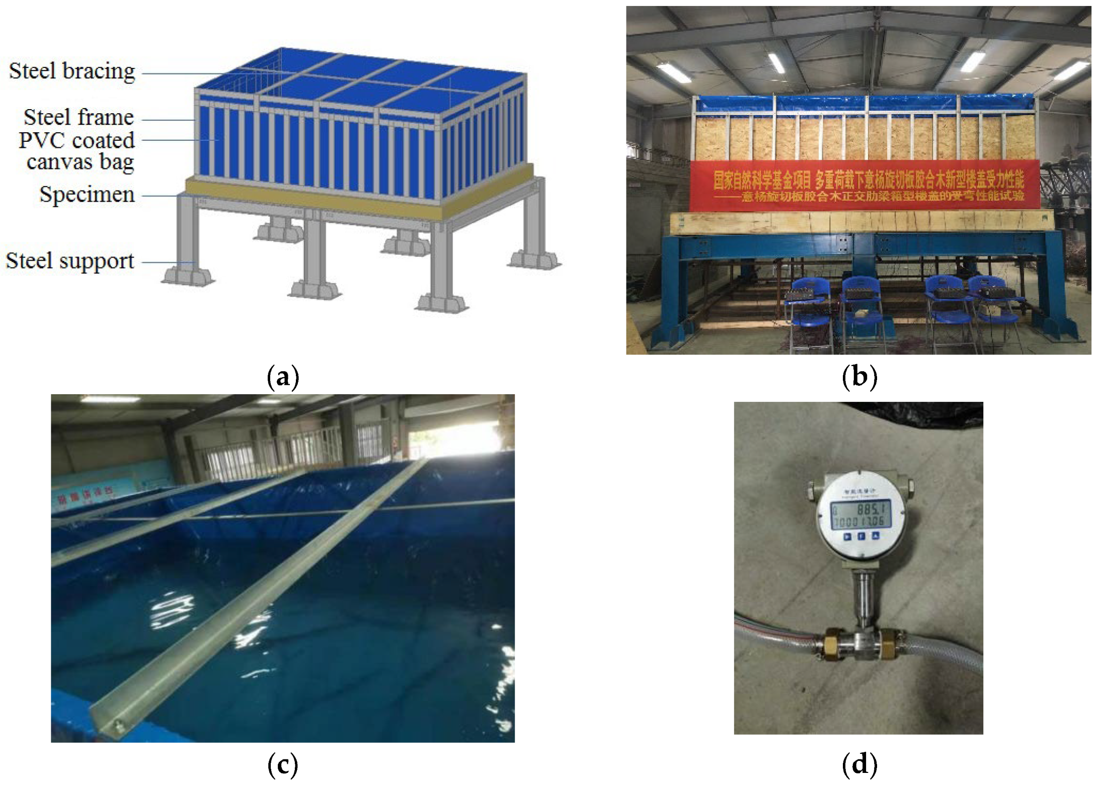
The design of the poplar LVL floor diaphragm specimen was in accordance with GB50005-2017 [27]. There were eight 3.6 m × 4.8 m specimens in total, and the spacing between the full-length rib beams (parallel to the short edge of 3.6 m) was 600 mm. The other details are shown in Figure 2 and Table 1. The sheathing panel for specimens L6 and L7 was a domestic OSB/2 grade (in accordance with LY/T1580-2010 [28]) plate with a thickness of 18.3 mm, which was connected to the rib beam by a nail of type P2.80 × 50LXL (in accordance with GB27704-2011 [29]), here the nail spacing for the inner beam and the edge beam were 300 mm and 150 mm respectively. For the traditional one-way floor specimen L8, the diagonal blocking was connected to the rib beam by 2 nails of type P2.80 × 60LXL (in accordance with GB27704-2011 [29]) at each end.
The L-shape connector and the corner connector were made of Q235 grade steel with a thickness of 3 mm, which were connected to the inner beam and edge beam by cross-recessed countersunk head tapping screws of type ST5.5 × 19 and ST5.5 × 38 (in accordance with GB/T846-2017 [30]) respectively, the details of the connectors are illustrated in Figure 3 and Figure 4 shows the photo of the finished specimens. The basic physical and mechanical properties of poplar LVL are shown in Table 2 [31].

2.2. Test Setup

The floor diaphragm specimen was loaded with a self-designed water tank device, composed of a steel frame and thick PVC-coated canvas bag, as shown in Figure 5. The height of the steel frame was 1.5 m, while the net height of the canvas bag was 1.6 m; the height difference of 100 mm was to ensure tight contact between the water bag and the specimen to transfer the load uniformly and deform with the specimen. To be more accurate, the water was metered by the flowmeter shown in Figure 5d.

2.3. Loading Scheme

The test loading was in accordance with GB/T503296-2012 [32] and ASTM E2322-03 [33], where step loading was adopted. A preloading at the level of 5% ultimate bearing capacity (which was evaluated by a numerical simulation) was first applied to the specimen, which would be sustained for 15 min. During the preloading stage, the loading device and the measuring instruments were checked to ensure proper working condition, and then the water tank would be evacuated. The formal loading stage began immediately after the preloading, in which the first loading level was set at 10% of the ultimate bearing capacity. The following loading steps were set at 5% of the ultimate bearing capacity; each loading step was sustained for 15 min, and the data was recorded after the reading of the measuring instrument became stable.

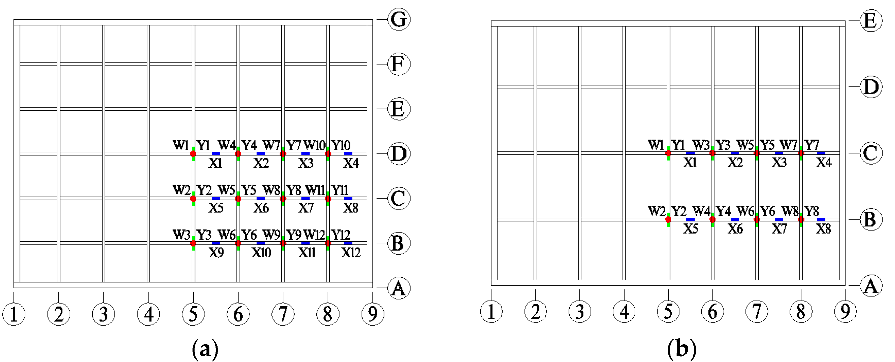
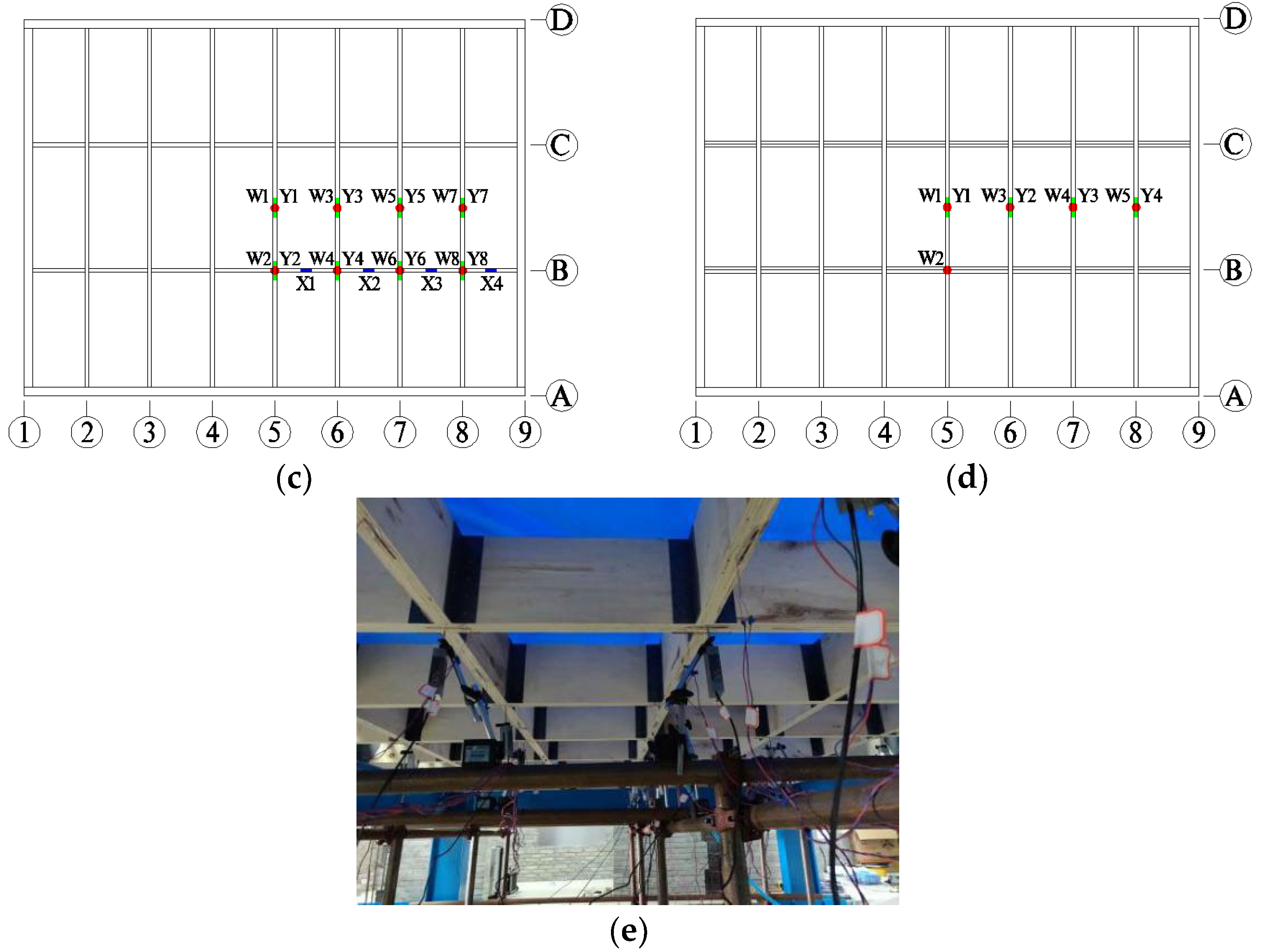
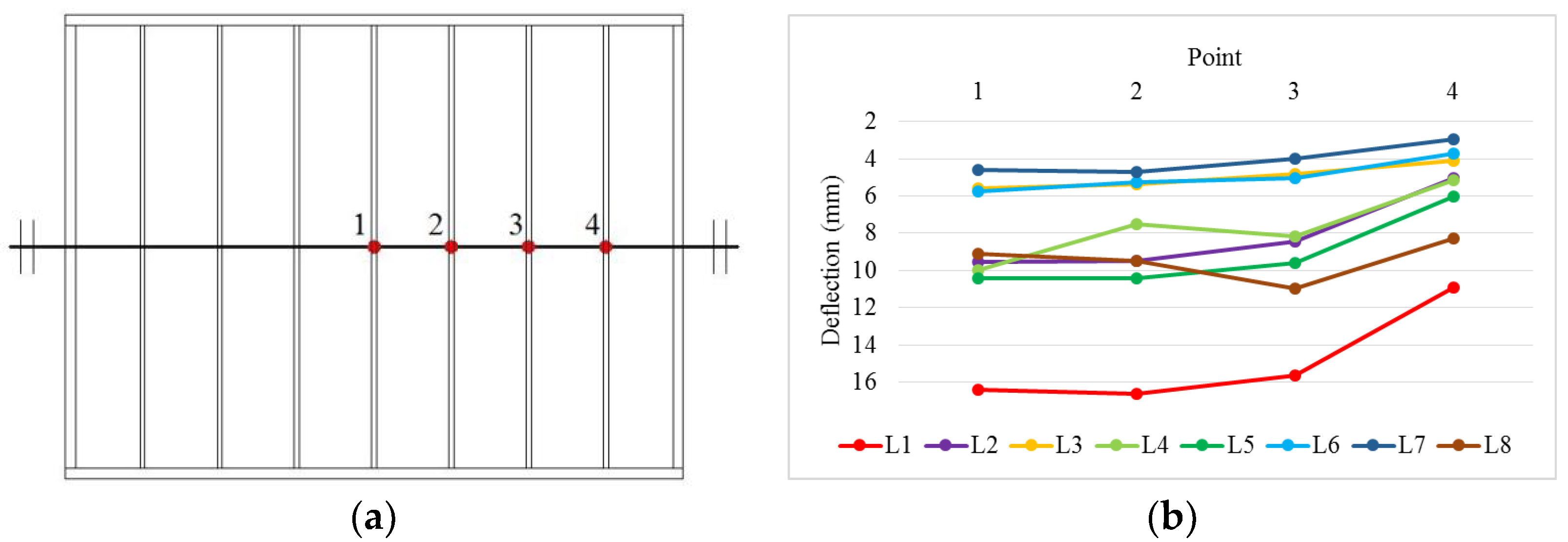
2.4. Measurement Points

To capture the global load-deformation behavior and the local stress and strain state, two kinds of measuring instruments were adopted: the displacement transducer and the strain gauge. Considering the symmetry characteristic for the load and structure, the layout of measurement points only covered 1/4 of the specimen, as shown in Figure 6.

3. Test Results

According to GB50009-2012 [34], the service loading level for the floor of the dwelling house is 2.5 kN/m2, and it could be observed that under the action of this loading level, there was no damage to any of the specimens. To investigate the possible failure pattern while ensuring the safety of personnel and instrument simultaneously, the maximum loading level was set at 7.5 kN/m2 for specimens L1~L5 & L8, set at 12 kN/m2 for specimen L6, and set at 13.5 kN/m2 for specimen L7, all much greater than the service loading level.

3.1. Testing Phenomena under the Maximum Loading Level

There was no overall failure for all the specimens till the maximum preset loading level, yet some local damage phenomena were observed as follows.
For specimens L1~L5 & L8, due to flexural deformation of the rib beam, the damage phenomena mainly exhibited as a separation between the rib beams (or between the diagonal blocking and the rib beam) and pulling out from the rib beam for the tapping screw, as shown by Figure 7a–c. It should be noted that for specimen L3 with the highest beam height of 285 mm, there wasn’t any damage till the maximum preset loading level of 7.5 kN/m2. For specimens L6 & L7, besides separation between the rib beams, slip also occurred between the beam and the panel (Figure 7d), which led to separations between the top panels and the bottom panels (Figure 7e,f).

3.2. Load-Deflection and Load-Strain Curves

Figure 8 shows the load-deflection and load-strain curves for the specimens. To illustrate the deformation of the floor (except for specimen L8), the deflection and strain distribution for 1/4 of the specimen under a service load of 2.5 kN/m2 is also presented in the figure.
Based on the variations between the curves of Figure 8, some loading characteristics of the specimens can be observed and inferred as follows:
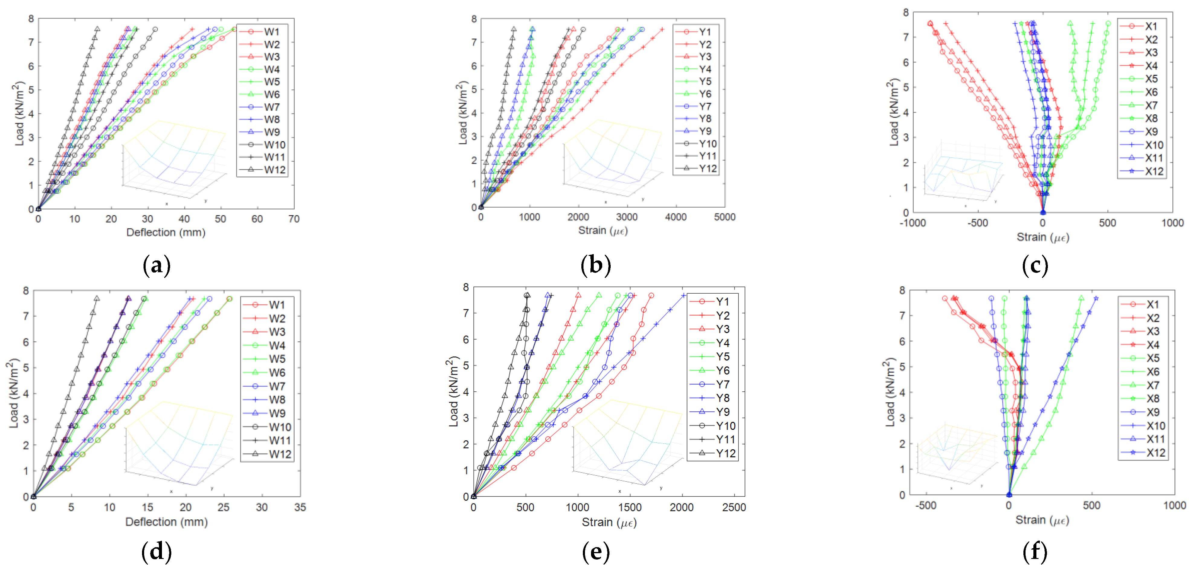
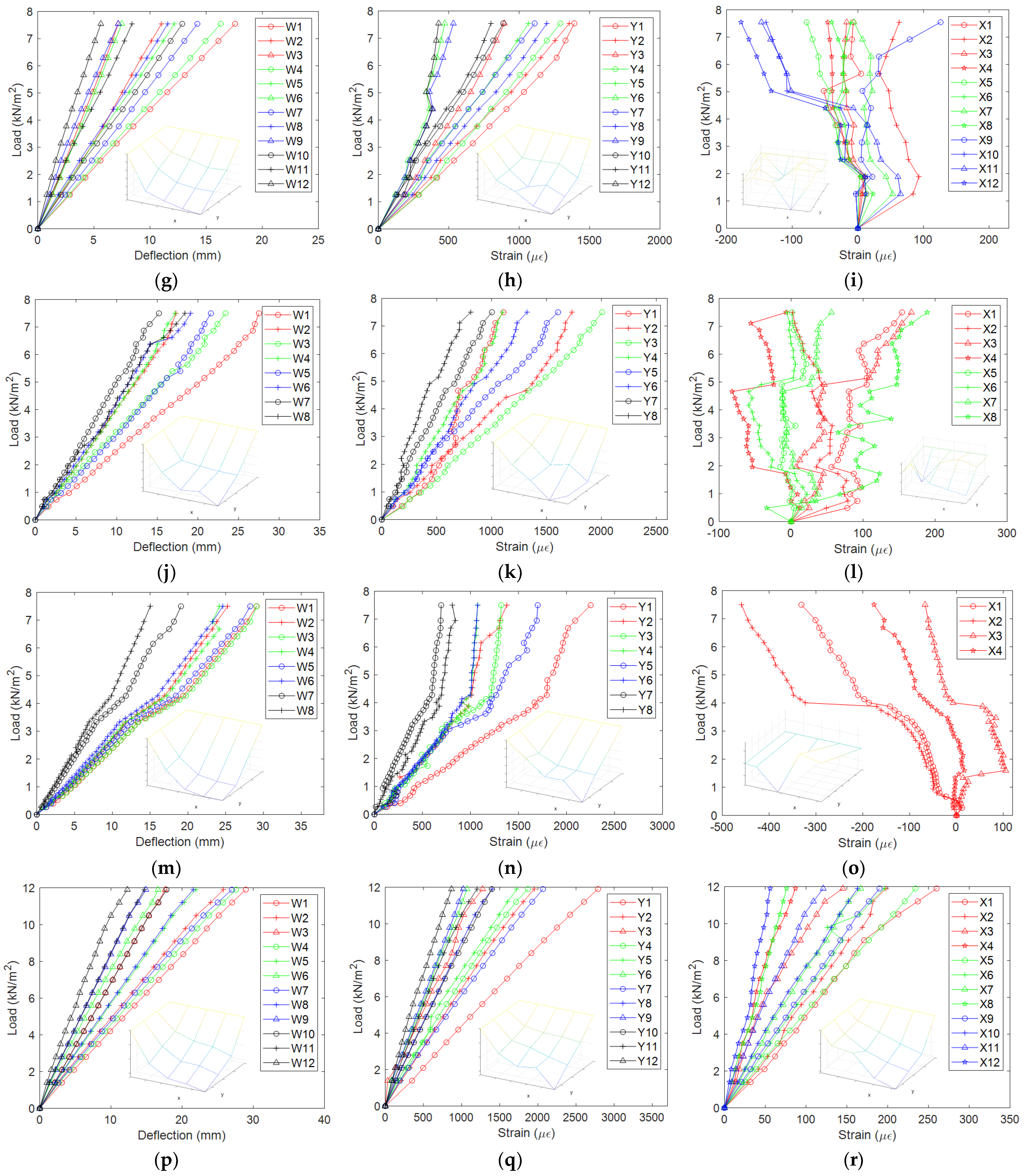
  • Under the service load of 2.5 kN/m2, the distribution of deflection and y-direction strain for the measuring points of 1/4 specimen is much more regular than that of x-direction strain (except for specimen L6), which generally demonstrates the typical shape of a “bowl” for the two-way slab under the action of transverse load. So for this type of floor diaphragm, the stress state of the segmented rib beam is much more complex than that of the full-length rib beam, which can also be reflected by the trend of the curves. Yet, for specimen L6 with only the top panel, due to a stronger integration for the top flange than for the bottom flange of the rib beam, the distribution of x-direction strain (Figure 8r) becomes much more regular.
  • Compared with the load-strain curves, the load-deflection curves are generally more “smooth”. This illustrates that for the wood floor, the load-strain curve can reflect some of the local damage phenomena, such as the separation between the beams and the panels, the pulling out of the tapping screw, etc., while some of the local damage doesn’t influence the global trend of the load-deflection curve.
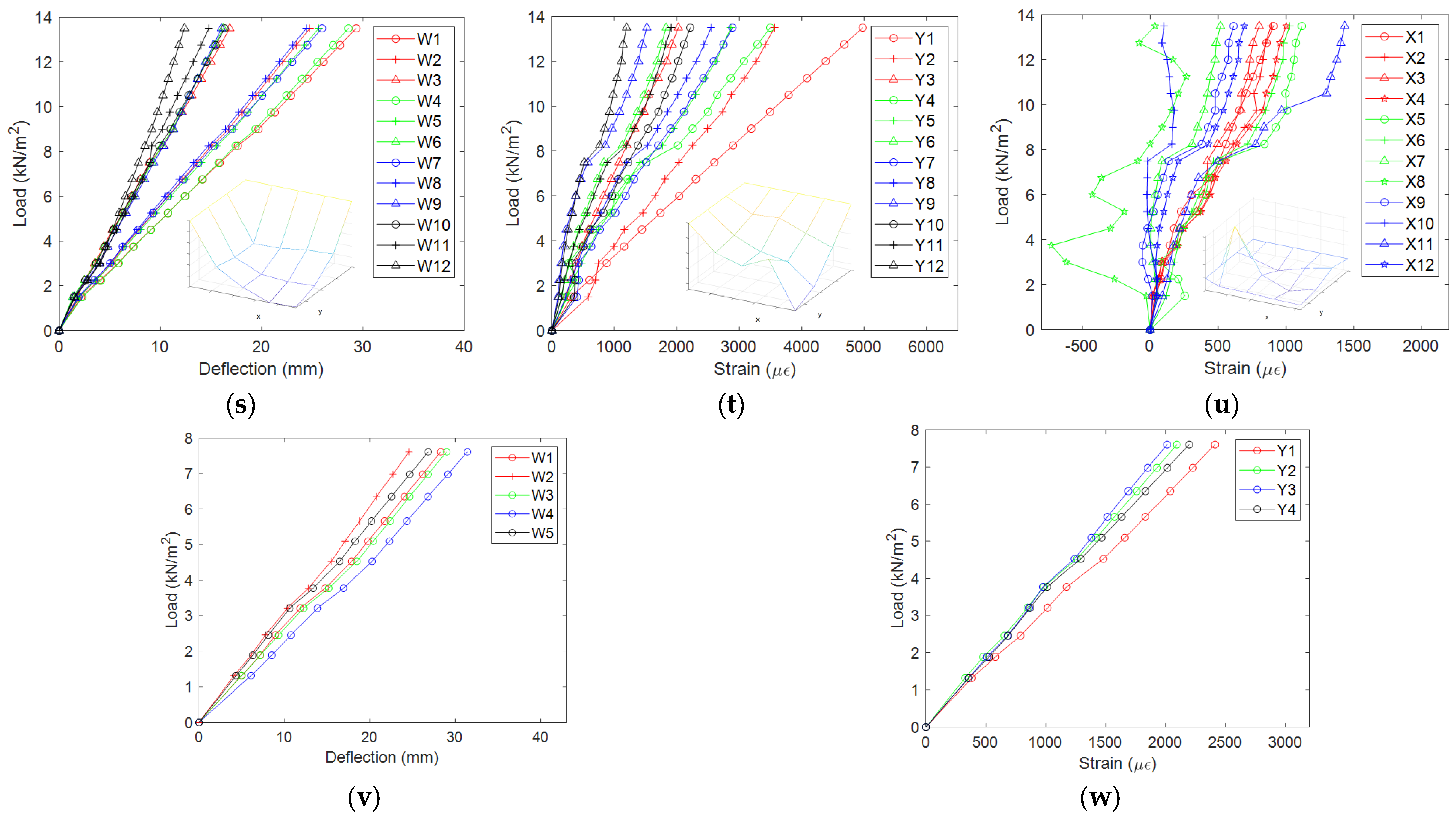
  • The load-deflection curves for specimens L1~L4 & L6~L8 are linear before the maximum preset loading level, except that the curves for specimens L1 & L6 emerge unremarkable inflection point at the loading level of 6.5 kN/m2 (Figure 8a) and 10.5 kN/m2 (Figure 8p) respectively, which reflects a slight decrease of the stiffness. The load-deflection curves for L5 show a remarkable decline stage between the loading levels of 3.3 kN/m2 and 4.3 kN/m2 (Figure 8m), then the slope recovers like before. Combined with the load-strain curve (Figure 8n,o), a credible explanation for this phenomenon is that the slope decline is due to the separation between the top edges of the full-length inner beam and the edge beam. In contrast, the slope recovery is due to the restraint for the beams’ lower edge by the segmented rib beam and the edge beam (the slope of the y-direction load-strain curve declines, and the x-direction strain becomes negative); therefore, something such as stiffness hardening happens.

4. General Discussion

Based on the parametric design of the specimens, the following discussion will be presented at the service loading level of 2.5 kN/m2.

4.1. Two-Way Slab Effect of the Floor Diaphragm

Four points of the specimen will be taken on the symmetry axis along the x-direction to illustrate the two-way slab effect (i.e., transmit transverse load along two orthogonal directions), as shown in Figure 9a. The deflection distribution for specimens L1~L8 is plotted in Figure 9b.
Due to the two-way slab effect, the deflections from point 1 to point 4 should decrease gradually, especially for points 3 and 4. So here we can find that the traditional type specimen L8 presents the weakest two-way effect, whose deflections for point 1~4 distribute nearly evenly (i.e., one-way slab effect), while specimens L1~L7 all exhibit typical two-way slab effect. Besides, the maximum deflection for specimen L8 is 10.96 mm, greater than specimen L5 with the same rib beam height and spacing.

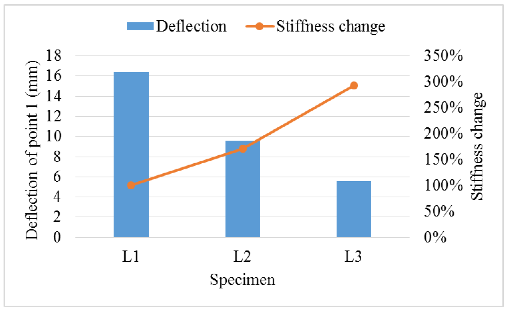
4.2. The Role of Beam Height in Floor Stiffness

The difference between specimens L1, L2 & L3 only lies in the rib beam height h, which is 185 mm, 235 mm & 285 mm, respectively. Here we will take the deflection of point 1 (Figure 9a) as the reference to compare the stiffness of the specimens, as shown in Figure 10. As it can be seen from Figure 10, when the rib beam height changes from 185 mm to 235 mm, and then to 285 mm, the transverse stiffness of the floor increases by 71.6% and 193.3%, accordingly.

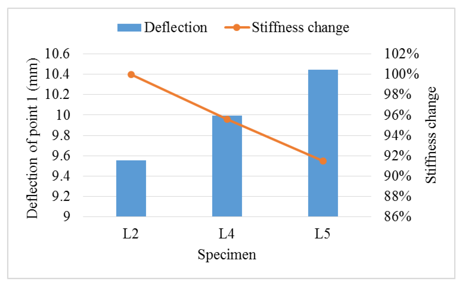
4.3. The Role of Segmented Rib Beam Spacing in Floor Stiffness

The distances between the segmented rib beams for specimens L2, L4 & L5 are 600 mm, 900 mm & 1200 mm, respectively. If we still take the deflection of point 1 (Figure 9a) as the reference to compare the stiffness of the floor, the result is shown in Figure 11. It can be found that the stiffness of the floor simply reduces by 8.5% when the rib beam spacing changes from 600 mm to 1200 mm.

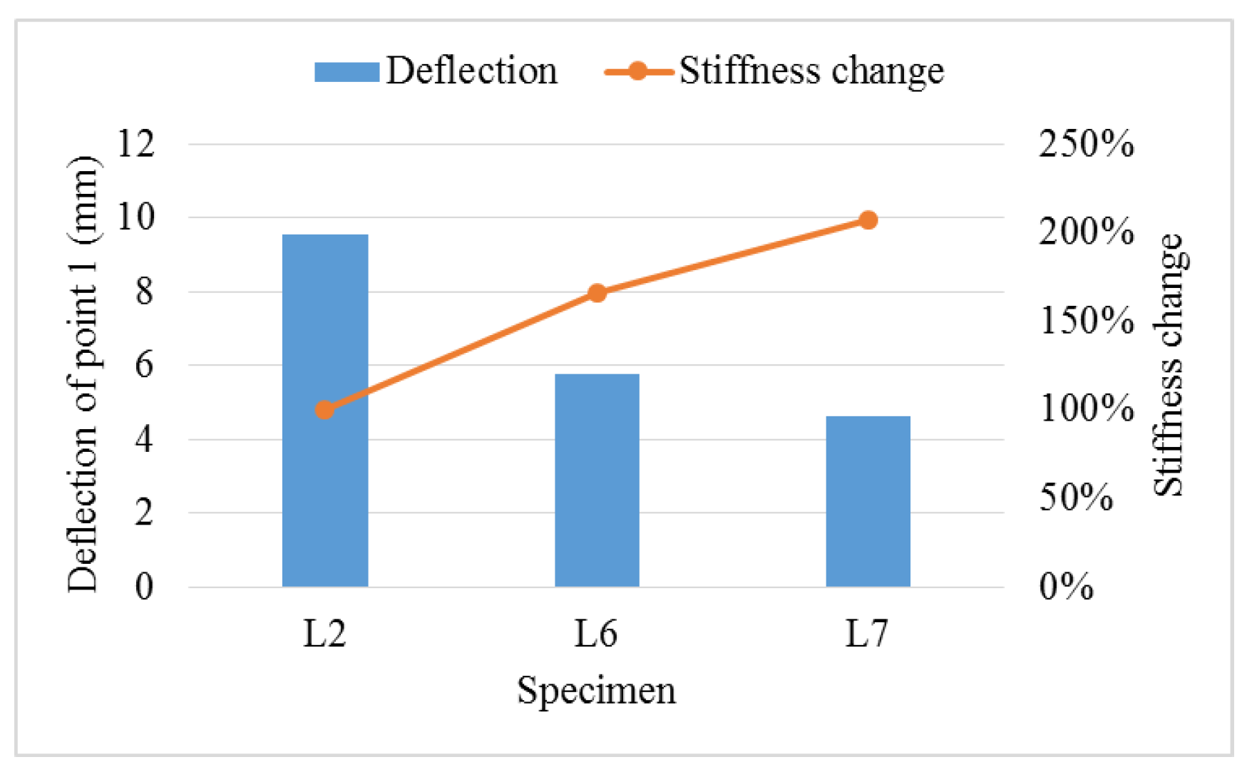
4.4. The Role of Top and Bottom Panels in Floor Stiffness

Specimens L2, L6 & L7 own the same rib beam height and spacing, while L6 is sheathed with top panel and L7 is sheathed with top and bottom panels. Referring to the deflection of point 1, Figure 12 illustrates the stiffness change for three specimens. What can be observed from the figure is that the top and bottom panels can significantly affect the stiffness of the floor, especially the top panel. Furthermore, Figure 8r shows that the distribution of x-direction strain is very regular for specimen L6 with only the top panel, which makes the floor more like a two-way slab. In other words, the segmented rib beams of specimen L6 demonstrate a more reasonable stress state.

5. Theoretical Evaluation and Analysis

Pseudo-plate method [35] will be adopted here to evaluate the maximum deflection (point 1, Figure 9a) of the innovative orthogonal rib beam floor analytically. According to this method, if the poplar LVL floor diaphragm is assumed to be an orthotropic plate, the flexural and torsional rigidity can be determined by
D 1 = E I x c 1 D 2 = E I y c 2 D 3 = 2 E h p 3 12 1 ν 2 + 0.5 G J tx c 1 + J ty c 2
where D 1   &   D 2 are the flexural rigidity along x and y directions, respectively, N·m; E is the elastic modulus, N/m2; I x   &   I y are the inertia moment of the rib beams along x and y directions, respectively, m4 (notice that for the sheathed floor, the OSB panel will be taken as the flange of the rib beam with a width of b b + 12 h f [36], where b b is the width of the rib beam, h f is the thickness of the flange); c 1   &   c 2 are the distance between the rib beams along x and y directions, respectively, m; D 3 is the torsional rigidity, N·m; h p is the thickness of the panel, m; ν is the Poisson’s ratio; G is the shear modulus, N/m2; J tx   &   J ty are the torsional rigidity of the rib beams along x and y directions, respectively, m4, which can be calculated by Equation (2):
J tx = b 1 h 1 3 + b 1 3 h 1 12 J ty = b 2 h 2 3 + b 2 3 h 2 12
in which b 1   &   b 2 are the rib beam width along x and y directions, respectively, m; h 1   &   h 2 are the rib beam height along x and y directions, respectively, m.
According to elastic orthotropic plate theory, the bending differential equation is
D 1 4 W x 4 + 2 D 3 4 W x 2 y 2 + D 2 4 W y 4 = q
The dual-trigonometric series solution for Equation (3) can be expressed as
W = 16 q π 6 m n sin m π x a sin n π y b m n D 1 m 4 a 4 + 2 D 3 m 2 n 2 a 2 b 2 + D 2 n 4 b 4 m , n = 1 , 3 , 5 ,
Here m   &   n will be taken as 1 under the action of uniformly distributed load, and the evaluated deflection results are shown in Figure 13a. It can be observed from Figure 13a that, due to the relatively poor integration of the wood structure, the evaluated deflections are all smaller than the experimental results, especially for the sheathed specimens L6 & L7. To consider the composite action due to connectors between the members of the floor, the rigidity factor can be introduced into Equation (1), which should be less than 1.0 (full composite action or full rigid connection), so we have
D 1 = k 1 E I x c 1 D 2 = k 2 E I y c 2 D 3 = k 3 2 E h p 3 12 1 ν 2 + 0.5 G k 1 J tx c 1 + k 2 J ty c 2
where k 1   and   k 2 are rigidity factors for x and y directions, respectively; k 3 is the rigidity factor for the sheathing panel. For convenient, I x   &   I y can be calculated by I = k 4 k 5 I b for the sheathed floor, in which I b is the inertia moment of the rib beam, k 4   &   k 5 are effective inertia moment factors for the top and bottom panels, respectively. Here the recommended values for the factors are k 1 = k 3 = 0.5 , k 2 = 0 .7, k 4 = 1 .7, k 5 = 1 .3, and the revised results are shown in Figure 13b, which are much more consistent with the experimental results.

6. Conclusions

This paper proposes an innovative poplar LVL orthogonal rib beam floor diaphragm. The main purpose of the paper was to draw attention to the bending behavior of the floor under a uniformly distributed load. The local strain of the rib beam and the floor deflection as a whole were studied via full-scale experimental tests, and some conclusions can be summarized as follows.
(1)
Under the service loading level of 2.5 kN/m2, there was no overall damage to any specimen. Under the preset maximum loading level, which is much greater than the service load, the local damage phenomena are mainly exhibited as a separation between the rib beams, pulling out from the rib beam for the tapping screw, and separation between the top panels and between the bottom panels. This means that for this kind of novel floor, evident phenomena before collapse can ensure the resident’s safety.
(2)
Despite some local damage, the global load-deflection curves for the specimens keep linear on the whole before the maximum preset loading level. Under a service load, the distribution of deflection and strain of the full-length rib beam substantially present the characteristic of a two-way slab, while the distribution of strain along the segmented rib beam is much more complex.
(3)
As to the transverse stiffness of the novel floor, taking specimen L2 as the reference shows that when the beam height changes from 235 mm to 285 mm, the bending stiffness increases by 71%; when the segmented rib beam spacing changes from 600 mm to 1200 mm, the bending stiffness decreases by 8.5%; and when the top panel is sheathed, the bending stiffness increases by 65.8%. So here, we can conclude that the rib beam height has the most important impact, followed by the top panel, while the role of spacing between the segmented rib beams is not particularly remarkable.
(4)
Considering the relatively poor integration of the wood construction, a revised pseudo-plate method based on the rigidity factor is proposed to evaluate the maximum deflection of the novel floor. Compared with the experimental values, the revised method reduces the mean error from 44% to 5%, which results meet well with the testing values.

Author Contributions

Conceptualization, Y.L.; methodology, Y.L. and X.S.; validation, C.W., H.M. and S.T.; formal analysis, X.S.; investigation, C.W. and S.T.; resources, Y.L.; data curation, X.S.; writing—original draft preparation, S.T.; writing—review and editing, X.S.; visualization, X.S.; supervision, H.M.; project administration, Y.L. and H.M.; funding acquisition, Y.L. All authors have read and agreed to the published version of the manuscript.

Funding

This research was funded by the National Natural Science Foundation of China (grant number: 51878590).

Institutional Review Board Statement

Not applicable.

Informed Consent Statement

Not applicable.

Conflicts of Interest

The authors declare no conflict of interest.

References

  1. Hematabadi, H.; Madhoushi, M.; Khazaeyan, A.; Ebrahimi, G.; Hindman, D.; Loferski, J. Bending and shear properties of cross-laminated timber panels made of poplar (Populus alba). Constr. Build. Mater. 2020, 265, 120326. [Google Scholar] [CrossRef]
  2. Countryman, D. Lateral Tests on Plywood Sheathed Diaphragms. In Laboratory Report, No. 55; Douglas-fir Plywood Association: Tacoma, WA, USA, 1952. [Google Scholar]
  3. Countryman, D.; Colbenson, P. Horizontal Plywood Diaphragm Tests; Laboratory Report, No. 63; Douglas-fir Plywood Association: Tacoma, WA, USA, 1954. [Google Scholar]
  4. Tissell, J.R. Horizontal Plywood Diaphragm Tests; Laboratory Report, No. 106; American Plywood Association: Tacoma, WA, USA, 1966. [Google Scholar]
  5. Corda, D.N. The In-Plane Shear Response of Timber Diaphragms. Master’s Thesis, West Virginia University, Morgantown, WV, USA, 1982. [Google Scholar]
  6. Zagajeski, S.W.; Halvorsen, G.T.; GangaRao, H.V.S.; Luttrell, L.D.; Jewell, R.B. Theoretical and Experimental Studies on Timber Diaphragms Subject to Earthquake Load; Laboratory Report NSF/CEE-84081; West Virginia University: Morgantown, WV, USA, 1984. [Google Scholar]
  7. Filiatrault, A.; Fischer, D.; Folz, B.; Uang, C.-M. Experimental parametric study on the in-plane stiffness of wood diaphragms. Can. J. Civ. Eng. 2002, 29, 554–566. [Google Scholar] [CrossRef]
  8. Xiong, H.B.; Kang, J.H.; Lv, X.L. Bending tests investigation on composite timber beam. J. Tongji Univ. Nat. Sci. 2012, 40, 522–528. [Google Scholar] [CrossRef]
  9. Awaludin, A.; Firmanti, A.; Muslikh; Theodarmo, H.; Astuti, D. Wood Frame Floor Model of LVL Paraserianthes falcataria. Procedia Eng. 2017, 171, 113–1200. [Google Scholar] [CrossRef]
  10. Rahman, W.M.N.W.A.; Yunus, N.Y.M.; Khaidzir, M.O.M.; Sani, M.S.H.M. Bending Behaviour of Different Types of Timber I-Joist. KSCE J. Civ. Eng. 2022, 26, 2202–2211. [Google Scholar] [CrossRef]
  11. Wang, B. Structural Behavior of Two-Way Wood Truss Floors. Master’s Thesis, Harbin Institute of Technology, Harbin, China, 2012. (In Chinese). [Google Scholar]
  12. Yeoh, D.; Fragiacomo, M.; Deam, B. Experimental behaviour of LVL–concrete composite floor beams at strength limit state. Eng. Struct. 2011, 33, 2697–2707. [Google Scholar] [CrossRef]
  13. Khorsandnia, N.; Valipour, H.R.; Crews, K. Experimental and analytical investigation of short-term behaviour of LVL–concrete composite connections and beams. Constr. Build. Mater. 2012, 37, 229–238. [Google Scholar] [CrossRef]
  14. Crocetti, R.; Sartori, T.; Tomasi, R. Innovative Timber-Concrete Composite Structures with Prefabricated FRC Slabs. J. Struct. Eng. 2015, 141, 04014224. [Google Scholar] [CrossRef]
  15. Shi, B.; Zhu, W.; Yang, H.; Liu, W.; Tao, H.; Ling, Z. Experimental and theoretical investigation of prefabricated timber-concrete composite beams with and without prestress. Eng. Struct. 2019, 204, 109901. [Google Scholar] [CrossRef]
  16. Loss, C.; Piazza, M.; Zandonini, R. Connections for steel–timber hybrid prefabricated buildings. Part I: Experimental tests. Constr. Build. Mater. 2016, 122, 781–795. [Google Scholar] [CrossRef]
  17. Loss, C.; Davison, B. Innovative composite steel-timber floors with prefabricated modular components. Eng. Struct. 2017, 132, 695–713. [Google Scholar] [CrossRef]
  18. Loss, C.; Frangi, A. Experimental investigation on in-plane stiffness and strength of innovative steel-timber hybrid floor diaphragms. Eng. Struct. 2017, 138, 229–244. [Google Scholar] [CrossRef]
  19. Hassanieh, A.; Valipour, H.; Bradford, M. Experimental and numerical investigation of short-term behaviour of CLT-steel composite beams. Eng. Struct. 2017, 144, 43–57. [Google Scholar] [CrossRef]
  20. Giongo, I.; Schiro, G.; Riccadonna, D. Innovative pre-stressing and cambering of timber-to-timber composite beams. Compos. Struct. 2019, 226, 111195. [Google Scholar] [CrossRef]
  21. Giongo, I.; Schiro, G.; Walsh, K.; Riccadonna, D. Experimental testing of pre-stressed timber-to-timber composite (TTC) floors. Eng. Struct. 2019, 201, 109808. [Google Scholar] [CrossRef]
  22. Ghanbari-Ghazijahani, T.; Russo, T.; Valipour, H.R. Lightweight timber I-beams reinforced by composite materials. Compos. Struct. 2019, 233, 111579. [Google Scholar] [CrossRef]
  23. Chiniforush, A.; Valipour, H.; Ataei, A. Timber-timber composite (TTC) connections and beams: An experimental and numerical study. Constr. Build. Mater. 2021, 303, 124493. [Google Scholar] [CrossRef]
  24. Hammad, M.; Valipour, H.; Ghanbari-Ghazijahani, T.; Bradford, M. Timber-timber composite (TTC) beams subjected to hogging moment. Constr. Build. Mater. 2022, 321, 126295. [Google Scholar] [CrossRef]
  25. Shahnewaz; Dickof, C.; Zhou, J.; Tannert, T. Vibration and flexural performance of cross-laminated timber—Glulam composite floors. Compos. Struct. 2022, 292, 115682. [Google Scholar] [CrossRef]
  26. Ramesh, M.; Rajeshkumar, L.; Sasikala, G.; Balaji, D.; Saravanakumar, A.; Bhuvaneswari, V.; Bhoopathi, R. A Critical Review on Wood-Based Polymer Composites: Processing, Properties, and Prospects. Polymers 2022, 14, 589. [Google Scholar] [CrossRef]
  27. GB 50005; Standard for Design of Timber Structures. Standardization Administration of China: Beijing, China, 2017. (In Chinese)
  28. LY/T 1580; Oriented Strand Board. Standardization Administration of China: Beijing, China, 2010. (In Chinese)
  29. GB 27704; Steel Nails. Standardization Administration of China: Beijing, China, 2011. (In Chinese)
  30. GB/T 846; Cross-Recessed Countersunk (Flat) Head Tapping Screws. Standardization Administration of China: Beijing, China, 2017. (In Chinese)
  31. Ding, P. Experimental Study on Flexural Performance of Poplar Laminated Veneer Lumber Box Beam. Master’s Thesis, Yangzhou University, Yangzhou, China, 2018. (In Chinese). [Google Scholar]
  32. GB/T 50329; Standard for Test Methods of Timber Structures. Standardization Administration of China: Beijing, China, 2012. (In Chinese)
  33. ASTM E2322-03; Standard Test Method for Conducting Transverse and Concentrated Load Tests on Panels Used in Floor and Roof Construction. ASTM International: West Conshohocken, PA, USA, 2015.
  34. GB 50009; Load Code for the Design of Building Structures. Standardization Administration of China: Beijing, China, 2012. (In Chinese)
  35. Liu, Q.; Yang, J.C. The pseudo-plate method for the design of large span rib floor. Build. Sci. 1997, 6, 30–34. (In Chinese) [Google Scholar] [CrossRef]
  36. GB 50010; Code for Design of Concrete Structures. Standardization Administration of China: Beijing, China, 2015. (In Chinese)
Figure 1. Poplar LVL orthogonal rib beam floor diaphragm.
Sustainability 14 10481 g001
Figure 2. Details of floor diaphragm specimens; (a) Novel orthogonal rib beam two-way diaphragm; (b) Traditional one-way diaphragm with blocking.
Sustainability 14 10481 g002
Figure 3. Details of steel connectors; (a) Inner connector; (b) Edge connector; (c) Corner connector.
Sustainability 14 10481 g003
Figure 4. The finished floor diaphragm specimens; (a) The floor specimen without top and bottom panels; (b) The floor specimen with top and bottom panels; (c) The traditional floor specimen with diagonal blocking.
Sustainability 14 10481 g004
Figure 5. Loading device; (a) Schematic diagram of the loading system; (b) Finished loading system (with funding information placed in front of the specimen); (c) Inner scene of the water tank; (d) Flowmeter.
Sustainability 14 10481 g005
Figure 6. Measurement points considered in the test; (a) Specimens L1, L2, L3, L6, L7; (b) Specimen L4; (c) Specimen L5; (d) Specimen L8; (e) Arrangement of measuring points. W-: inductive displacement transducer; Y-: strain gauge along the y-direction; X-: strain gauge along the x-direction.
Sustainability 14 10481 g006aSustainability 14 10481 g006b
Figure 7. Local damage phenomena for the specimens; (a) Separation between the rib beams; (b) Pulling out for the tapping screw; (c) Separation between the diagonal blocking and the rib beam; (d) Slip between the beam and the panel; (e) Separation between the top panels; (f) Separation between the bottom panels.
Sustainability 14 10481 g007
Figure 8. Load-deflection and Load-strain curves for the specimens; (a) Load-deflection curve for specimen L1; (b) Y-direction load-strain curve for specimen L1; (c) X-direction load-strain curve for specimen L1; (d) Load-deflection curve for specimen L2; (e) Y-direction load-strain curve for specimen L2; (f) X-direction load-strain curve for specimen L2; (g) Load-deflection curve for specimen L3; (h) Y-direction load-strain curve for specimen L3; (i) X-direction load-strain curve for specimen L3; (j) Load-deflection curve for specimen L4; (k) Y-direction load-strain curve for specimen L4; (l) X-direction load-strain curve for specimen L4; (m) Load-deflection curve for specimen L5; (n) Y-direction load-strain curve for specimen L5; (o) X-direction load-strain curve for specimen L5; (p) Load-deflection curve for specimen L6; (q) Y-direction load-strain curve for specimen L6; (r) X-direction load-strain curve for specimen L6; (s) Load-deflection curve for specimen L7; (t) Y-direction load-strain curve for specimen L7; (u) X-direction load-strain curve for specimen L7; (v) Load-deflection curve for specimen L8; (w) Y-direction load-strain curve for specimen L8.
Sustainability 14 10481 g008aSustainability 14 10481 g008bSustainability 14 10481 g008c
Figure 9. Deflection distribution for the points along the symmetry axis; (a) Points 1~4 along the x-direction symmetry axis; (b) Deflection distribution for points 1~4.
Sustainability 14 10481 g009
Figure 10. Influence of the beam height on floor stiffness.
Sustainability 14 10481 g010
Figure 11. Influence of the segmented rib beam spacing on floor stiffness.
Sustainability 14 10481 g011
Figure 12. Influence of the top and bottom panels on floor stiffness.
Sustainability 14 10481 g012
Figure 13. Theoretical evaluation for the maximum deflection of the floor; (a) Pseudo-plate method; (b) Revised pseudo-plate method.
Sustainability 14 10481 g013
Table 1. Parameters for floor diaphragm specimens.
SpecimenTypes (mm)h (mm)Top PanelBottom Panel
L1Two-way600185NoneNone
L2Two-way600235NoneNone
L3Two-way600285NoneNone
L4Two-way900235NoneNone
L5Two-way1200235NoneNone
L6Two-way600235YesNone
L7Two-way600235YesYes
L8One-way1200235NoneNone
Table 2. Physical and mechanical parameters of poplar LVL.
Moisture Content
(%)
Density
(g/cm3)
Tensile Strength Parallel to Grain
(MPa)
Compression Strength Parallel to Grain
(MPa)
Compression Strength Perpendicular to Grain
(MPa)
Bending Strength (MPa)Flexural Elastic Modulus (MPa)
Adhesive Layer HorizontalAdhesive Layer VerticalAdhesive Layer HorizontalAdhesive Layer Vertical
12.80.57639.437.036.361.5664.89877.310,135.4
Publisher’s Note: MDPI stays neutral with regard to jurisdictional claims in published maps and institutional affiliations.

