Article

Strategy Design and Performance Analysis of an Electromechanical Flywheel Hybrid Scheme for Electric Vehicles

School of Transportation and Vehicle Engineering, Shandong University of Technology, Zibo 255000, China
*
Author to whom correspondence should be addressed.
Sustainability 2022, 14(17), 11017; https://doi.org/10.3390/su141711017
Submission received: 27 July 2022 / Revised: 31 August 2022 / Accepted: 1 September 2022 / Published: 3 September 2022

Abstract

:
Energy management strategies are one of the key factors affecting the working efficiency of electric vehicle energy power systems. At present, electric vehicles will develop real-time and efficient energy management strategies according to the topology of on-board energy power system to improve the driving performance of vehicles. In this paper, a new electromechanical flywheel hybrid system is studied. Firstly, the characteristics of the topological scheme of the electromechanical flywheel hybrid system are analyzed, and the working modes are designed. Secondly, in order to improve the efficiency of vehicles’ energy utilization and ensure the real-time performance of the management strategy, an energy management strategy based on fuzzy rules is designed with the flywheel’s state of energy (SOE) as the key reference parameter. Then, considering the directional stability in the braking process, the braking force distribution strategy between the front axle and the rear axle is designed. In order to improve the braking energy recovery efficiency, the secondary distribution strategy consisting of a mechanical braking force and regenerative braking force on the front and rear axles is designed. Finally, the bench test of a electromechanical flywheel hybrid system is carried out. Experiments show that compared with the original dual-motor four-wheel drive scheme, the electromechanical flywheel hybrid four-wheel drive system scheme developed in this paper can reduce the current variation range of lithium batteries by 43.16%, increase the average efficiency by 1.04%, and increase the braking energy recovery rate by 40.61% under the Japan urban cycle conditions. In addition, taking advantage of the energy and power regulation advantages of the electromechanical flywheel device, the power consumption of the lithium battery is reduced by 1.82% under cycling conditions.

1. Introduction

The development of electric vehicles can reduce fuel consumption, carbon emissions, and pollutant emissions in the transportation field, and electric vehicles are considered to be an important direction for the future development of the automotive industry [1,2]. However, the promotion of electric vehicles is also associated with many inconveniences, the biggest of which are: high purchase expenses, poorly developed charging infrastructure, and long charging times [3]. In addition, due to the low energy density of lithium batteries, the driving range of electric vehicles has become a key issue in their promotion and application [4]. On the basis of limited on-board energy, improving the energy utilization efficiency of whole vehicles can improve the driving range of electric vehicles, and the research on related issues has been widely concerned [5,6].
As far as energy utilization is concerned, the common topology scheme of the energy power system of electric vehicles is a single energy centralized drive. The scheme has problems such as a low motor efficiency under low load conditions, high power and low efficiency charge and the discharge of batteries under sudden conditions, and limited energy feedback under high braking intensity conditions [7,8]. With the development of electro-electric compound energy sources and distributed configuration schemes, the range of operating conditions for the efficient operation of electric vehicles has been improved to a certain extent [9,10]. However, at present, the electro-electric composite energy scheme still cannot realize the efficient operation of the motor under urban low load conditions, and the distributed drive scheme has not yet solved the problem of low on-board energy efficiency under frequent acceleration and high braking intensity conditions in urban areas [11,12].
Nowadays, flywheel energy storage technology, which has the advantages of high energy conversion efficiency and high power density, has been applied in aerospace, emergency power, and other fields [13,14,15]. From the perspective of the energy input and output mode, the common flywheel energy storage system can be summarized as an electric energy storage system and a mechanical energy storage system [16]. Among them, high energy storage and low self-consumption are the key parameters to measure the performance of flywheel energy storage systems, which needs to be achieved through the design and control of ultra-high-speed and efficient flywheels. It involves technical problems and high costs, such as composite materials, magnetic bearings, and vacuum chambers, which limit the application of flywheel energy storage systems in automobiles [17,18]. The characteristics of vehicle driving conditions, especially the frequent intermittent braking conditions under urban conditions, determine the intermittent but continuous energy supplement of vehicle flywheel energy storage systems [19], which helps to reduce the design requirements of vehicles for tje flywheel energy storage and self-consumption rate to a certain extent.
Based on the above issues, an electromechanical flywheel device based on a planetary gear mechanism is developed, which achieves continuously variable electric transmission through a planetary gear mechanism and a speed-regulating motor to meet the needs of speed change. Depending on the instantaneous energy regulation of the flywheel rotor and the instantaneous power regulation of the device, the variation range of the charging and discharging power of the main energy source can be reduced, and its efficiency can be improved. Then, the miniaturization design of the main drive motor and the working efficiency optimization of the power system can be realized [20]. To use the unique energy and power regulation characteristics of the electromechanical flywheel device, it is necessary to formulate a matching energy management strategy according to the vehicle energy topology scheme.
At present, electric vehicle energy management strategies can be divided into rule-based algorithms and optimization-based algorithms according to the algorithm types [21,22]. Among them, the energy management strategy based on rule-based algorithms has clear energy interaction rules, a simple algorithm structure, and strong real-time performance, but it could not achieve the optimization of energy utilization efficiency [23,24]. Li Chen et al., from the University of Michigan, used a rule-based control strategy to select and control the working mode of the proposed dual planetary power split hybrid system [25]. Behrooz Mashadi et al. designed a controller based on fuzzy logic for the dual-mode power split hybrid system. The controller accepts the battery state of charge (SOC), vehicle speed, and required power signal of the wheel to coordinate the various components and optimize the efficiency of the system [26]. Anil K. Madhusudhanan proposed a modeling framework for the energy consumption of ICE and electric vehicles, with advantages of high computational efficiency and accuracy [27]. Energy management strategies based on the optimization algorithm can realize the efficient utilization of vehicle energy, although the real-time performance is poor [28,29]. The most representative is the dynamic programming (DP) control strategy, which needs to predict the entire driving conditions and requires a large amount of calculation, which cannot meet the real-time application requirements. However, the DP control strategy can be used as a standard to compare and evaluate other energy management optimization algorithms. Namwook Kim et al., from Seoul University, used a transient optimal control strategy to perform real-time optimal power distribution for hybrid vehicles with THS coupled power systems [30]. Therefore, in order to maximize the regulating effect of electromechanical flywheel devices on vehicles’ energy utilization efficiency and ensure the real-time performance of engineering applications, an energy management strategy based on fuzzy rules is proposed in this paper. In Section 1, the topological structure of the energy power system of the electromechanical flywheel hybrid electric vehicle is explained, and the working mode of the electromechanical flywheel hybrid electric vehicle is designed. In Section 2 and Section 3, the driving and braking energy management strategies based on fuzzy rules are designed, respectively. In Section 4, the energy management strategy is verified by experiments, and the economy performance of the vehicle is analyzed.

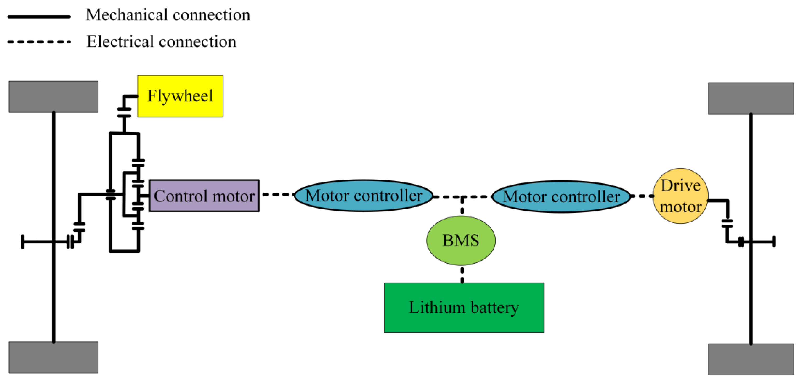
2. Topological Scheme and Working Principle of Electromechanical Flywheel Hybrid Systems

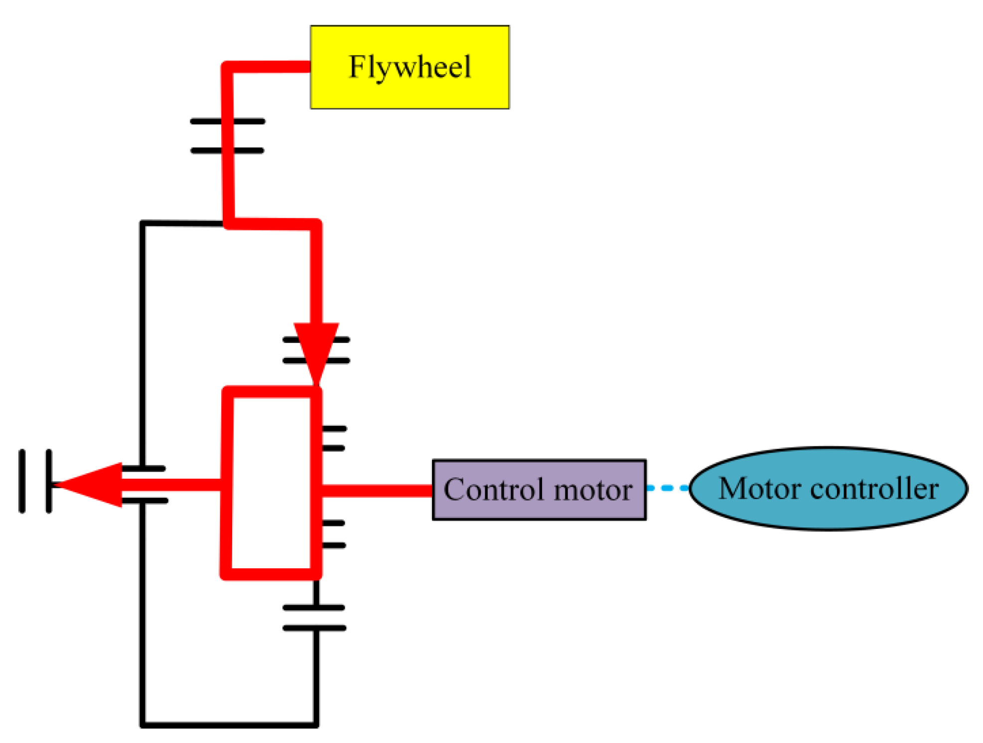
2.1. Topological Scheme of Electromechanical Flywheel Hybrid Systems

Based on the early research on the dual-motor four-wheel drive scheme [9,12], compared with the single-motor drive scheme, this scheme can improve the efficiency of a vehicle’s powertrain, but it cannot cope with the problem of efficiency reductions caused by high-current charging and discharging of lithium batteries. To this end, the research team designed a four-wheel-drive solution based on an electromechanical flywheel hybrid system. As shown in Figure 1, the electromechanical flywheel hybrid system consists of a rear axle main drive motor and a front axle electromechanical flywheel device. The front axle electromechanical flywheel hybrid device is composed of a planetary gear mechanism, speed-regulating motor, and flywheel. The sun gear of the planetary gear mechanism is connected with the speed-regulating motor, the ring gear is connected with the flywheel, and the planet carrier is connected with the main reducer at the front. The electromechanical flywheel device mainly plays a regulating role. First, with the advantage of flywheel energy storage, it can adjust the power of the lithium battery and improve the working efficiency of the battery. Second, flywheel energy storage is used to increase vehicles’ braking energy recovery.

2.2. Design of Working Mode of Electromechanical Flywheel Hybrid Systems

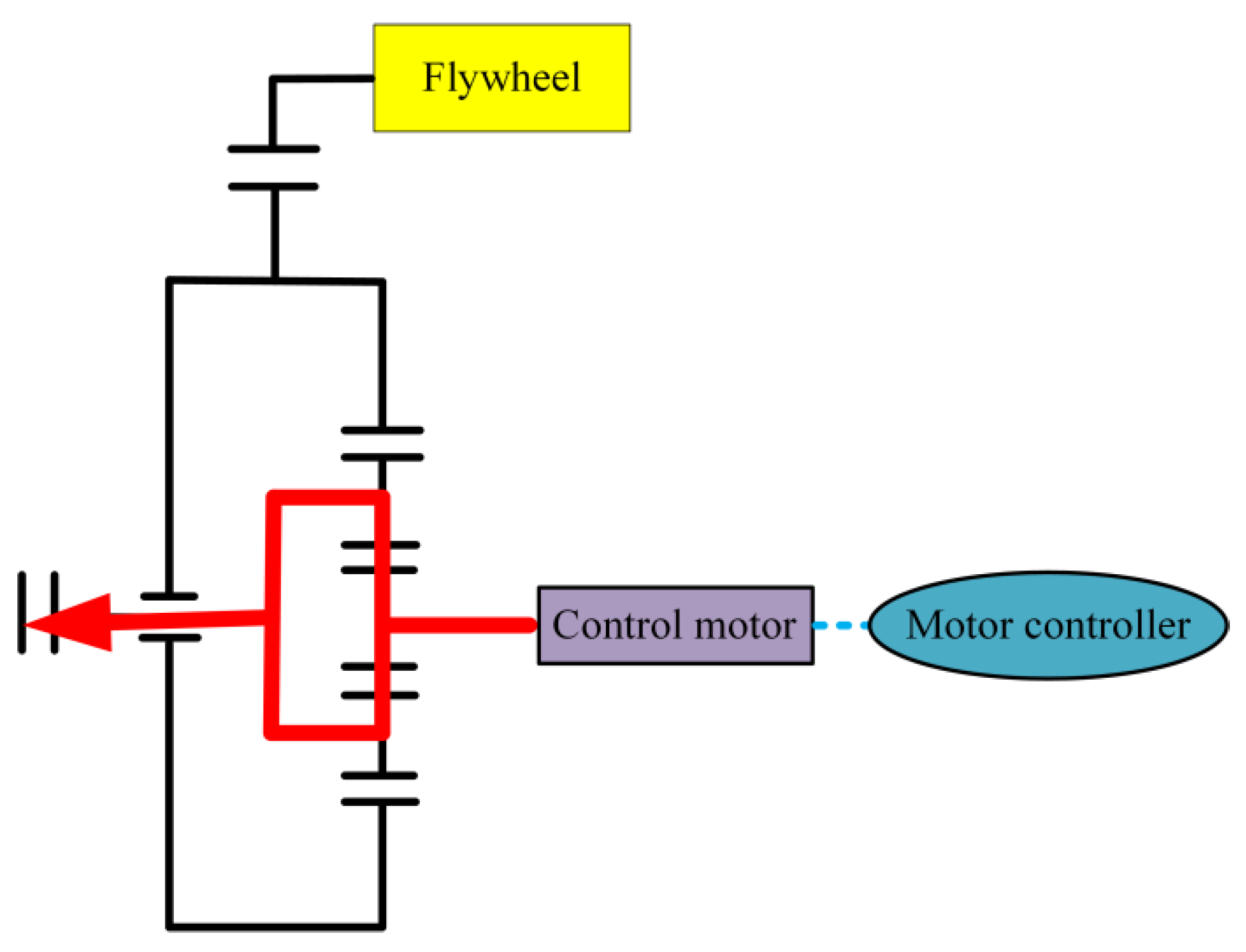
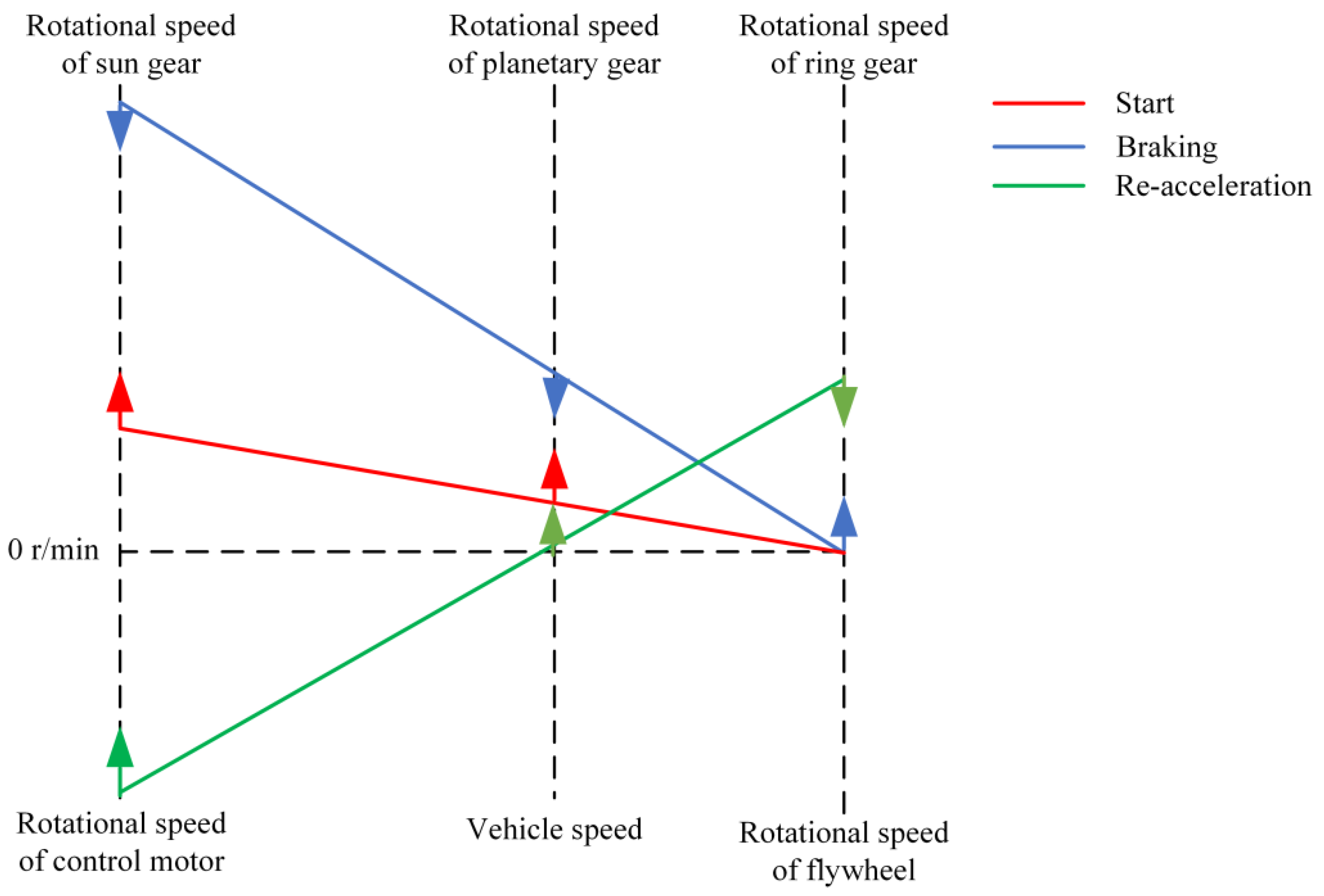
2.2.1. Initial Acceleration Stage

As shown in Figure 2, the vehicle starts to accelerate from a standstill, and the rear axle main drive motor provides positive torque. The speed-regulating motor in the electromechanical flywheel device of the front axle works in the motor state and provides positive torque. At this point, the flywheel speed is 0 rpm. Due to the restrictions of the one-way locking mechanism, the flywheel rotates reversely and locks, and the gear ring of the planetary gear mechanism locks. The torque of the speed-regulating motor is input through the sun gear, and the planetary gear is amplified by (1 + k) times and output by the planetary frame. At this stage, the lever relationship among the speed-regulating motor speed, speed of the flywheel, and speed in the electromechanical flywheel device is shown in Figure 3.

2.2.2. Constant Speed Driving Stage

The vehicle runs at a constant speed, and the main drive motor of the rear axle provides positive torque. The speed-regulating motor of the electromechanical flywheel device provides positive torque, and the flywheel is still locked in reverse. On the whole, the working principle of the electromechanical flywheel system is the same as that of the starting acceleration stage shown in Figure 2, during the constant speed driving stage.

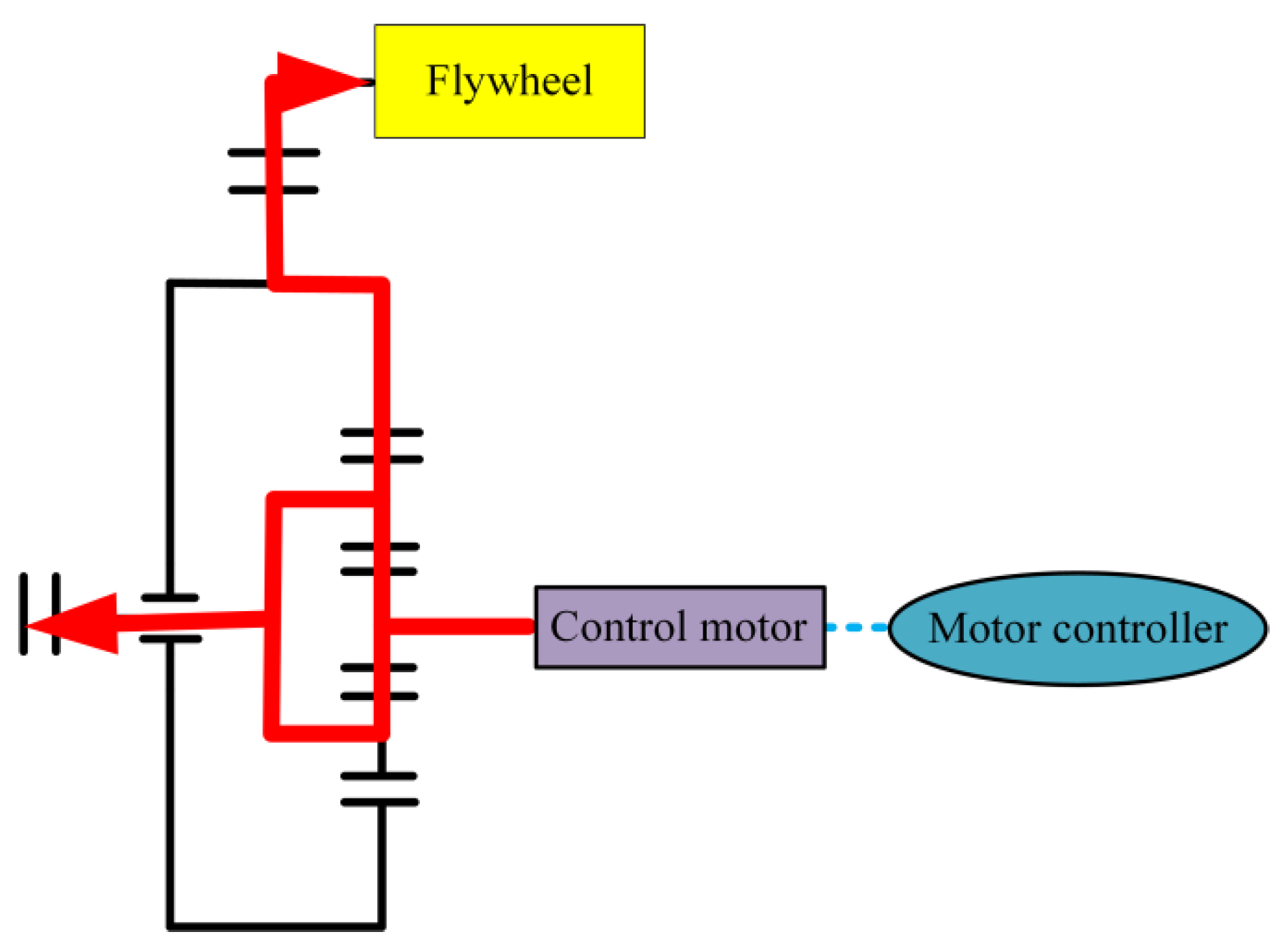
2.2.3. Braking Deceleration Stage

As shown in Figure 4, when the vehicle starts to decelerate, the rear axle main drive motor provides a regenerative braking force according to the allocated regenerative braking torque. The internal speed-regulating motor in the front axle flywheel hybrid works as a generator to recover braking energy and provide negative torque. The planetary gear mechanism will split the negative torque. Part of it is amplified by (1 + k) times and output through the planet carrier to provide braking torque for the vehicle, and part of it will be amplified by k times and output by the gear ring and acceleration gear, acting on the flywheel to accelerate the rotation of the flywheel.
Due to the speed relationship of the sun gear, the planet carrier, and the ring gear and the limitation of the moment of inertia, the speed of the speed-regulating motor is first reduced to 0 rpm before the vehicle slows down to a stop. At this time, the vehicle continues to decelerate, the speed-regulating motor still provides negative torque, enters the negative speed range, and works in the motor state, and the flywheel speed continues to increase. Part of the recovered braking energy is converted into electrical energy by the control motor and stored in the vehicle’s power battery, and the other part is stored as mechanical energy of the flywheel’s rotation. At this stage, the lever relationship among the speed-regulating motor speed, speed of the flywheel, and speed of the electromechanical flywheel device is shown in Figure 3.

2.2.4. Re-Acceleration Stage

As shown in Figure 5, the rear axle main drive motor provides driving force for the rear axle according to the torque allocated by the energy management strategy. The flywheel in the front axle’s electromechanical flywheel device runs at a certain speed. In this stage, the speed-regulating motor provides positive torque, and the flywheel speed decreases, which also provides positive torque. The positive torque provided by the flywheel is amplified by the reduction gear and then acts on the ring gear. The planetary gear mechanism couples the positive torque provided by the flywheel and the motor, amplifies it by (1 + k) times, and then outputs it by the planet carrier. The speed-regulating motor and the flywheel together provide the torque required for vehicle acceleration. At this stage, the lever relationship among the speed-regulating motor speed, speed of the flywheel, and speed of the electromechanical flywheel device is shown in Figure 3.

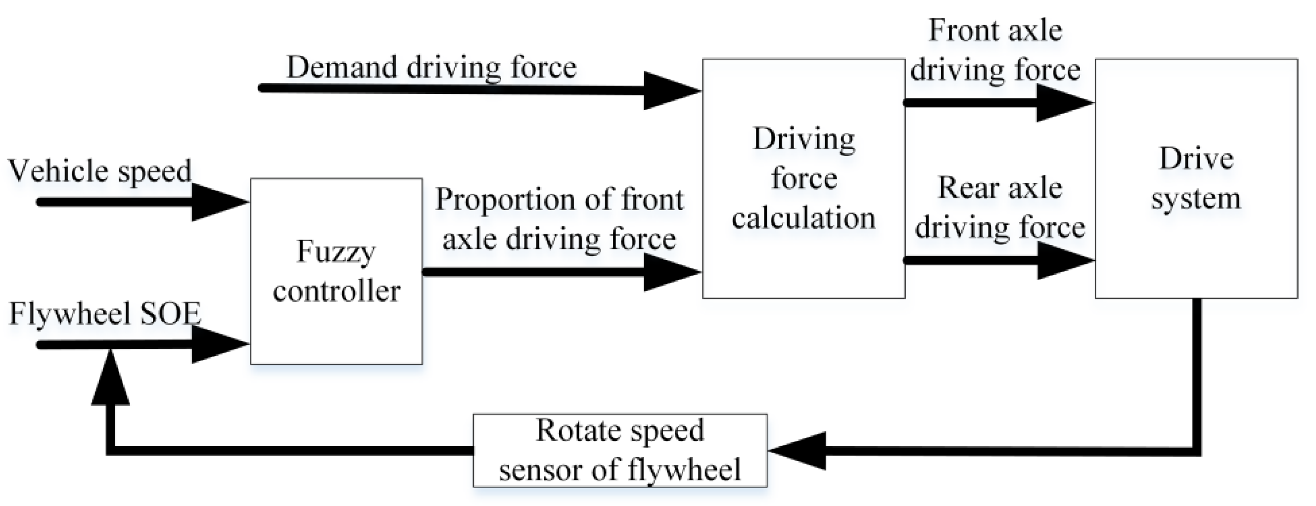
3. Design of Energy Management Strategies for Driving Mode

As shown in Figure 6, fuzzy control is mainly divided into two parts. The first part is the design of the fuzzy controller. The input of the fuzzy controller is two key parameters, flywheel SOE and vehicle speed, and the torque ratio parameter K of the front axle of the vehicle is output through the fuzzy controller. The flywheel speed in the electromechanical flywheel system is transmitted to the flywheel SOE calculator through the flywheel speed sensor, and the SOE of the flywheel is calculated, updated, and input to the fuzzy controller. The second part is the calculation and distribution of the vehicle driving force. Among them, the driving torque required for the entire vehicle is calculated according to the accelerator pedal stroke depressed by the driver. Then, according to the proportion of the torque demanded by the front axle of the vehicle, the respective driving torque of the flywheel control motor, flywheel, and the drive motor is calculated, and this signal is finally sent to the actuator.
The three membership functions of the drive fuzzy controller are flywheel SOE, vehicle speed V, and the speed-regulating motor torque distribution coefficient K. As shown in Table 1, the domain of the flywheel SOE is [0 1], and the fuzzy set of input quantities is SOE = {L M B}. The domain of vehicle speed V is [0 180], and the fuzzy set of input quantities is V = {L M B}. The domain of the controlling motor torque distribution coefficient K is [0 1], and the fuzzy set of output quantities is K = {L ML MB B}. In the Table 1, L, ML, M, MB, and B represent small, medium-small, medium, medium-large, and large fuzzy quantities, respectively. After selecting and setting the membership function, the fuzzy control rules are set.
The formulation principle of the fuzzy control rules as shown in Table 1 is: when the SOE of the flywheel is medium and high, the energy of the flywheel is given priority to release quickly. When the flywheel SOE is low, the speed at which the flywheel releases energy and the impact on the system when the flywheel speed drops to 0 rpm are reduced. As shown in Figure 7, if the flywheel SOE is higher than 0.75, the ratio of the front axle to the total torque can reach 0.8. At this time, the speed of the flywheel is high, and it is necessary to release energy quickly to reduce the speed. When the SOE of the flywheel is higher than 0.5, the flywheel still releases energy rapidly. However, when the SOE of the flywheel is lower than 0.15, the speed of the flywheel is less than 1500 rpm. If the energy is released by the high torque, the flywheel will be locked by the one-way locking mechanism when the speed drops to 0 rpm rapidly. If the speed is too fast, it will have an impact on the system, so after the flywheel SOE is lower than 0.15, the flywheel releases energy with a small torque, and its speed drops relatively slowly, reducing the impact on the system when the flywheel is locked.

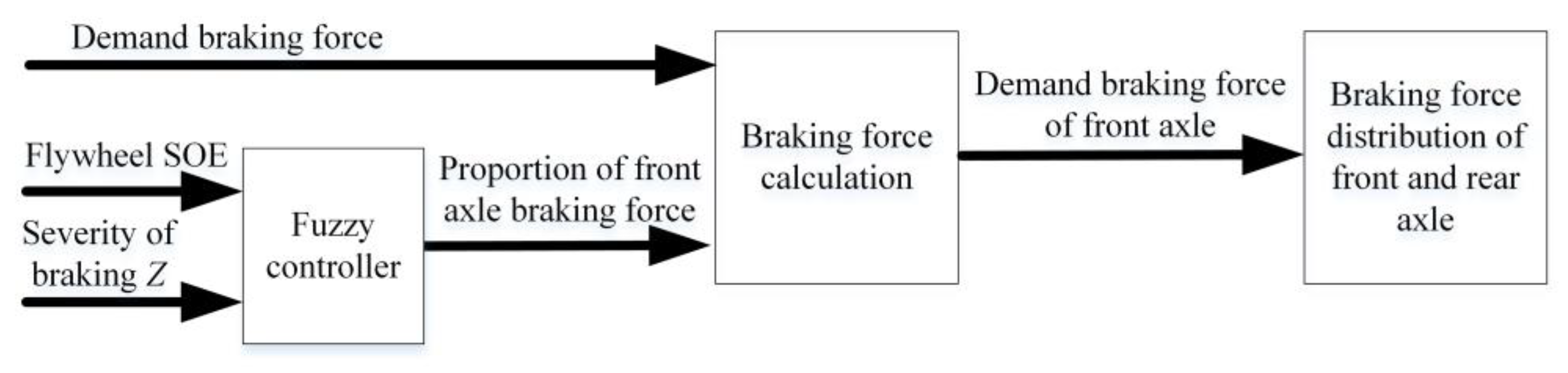
4. Design of Energy Management Strategies in Braking Mode

Since the electromechanical flywheel hybrid system can achieve four-wheel regenerative braking energy recovery, the design of the vehicle energy management strategy in braking mode involves two aspects. The first is the design of the braking force distribution between the front axle and the rear axle. The design principle is to give priority to ensuring the stability of the whole vehicle when braking. On this basis, the design of mechanical braking, flywheel braking, and the motor braking distribution in the front axle is further carried out, and the design of mechanical braking and the motor braking distribution in the rear axle is carried out. The design principle is to give priority to ensuring the braking energy’s recovery efficiency.

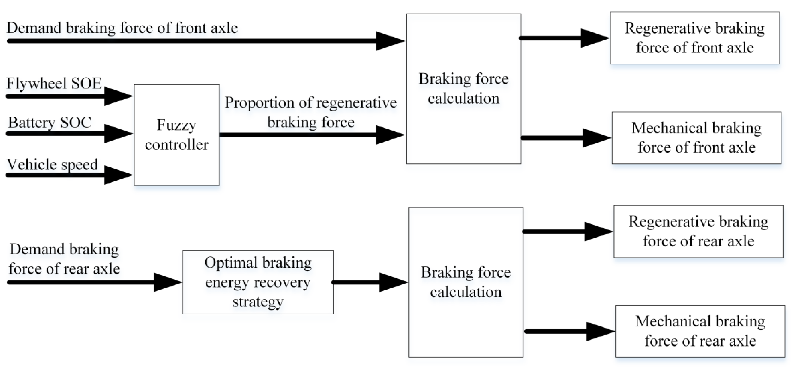
4.1. Design of a Braking Force Distribution Strategy for Front and Rear Axles

In order to ensure the braking stability of the whole vehicle, the ideal braking force distribution equation of the front and rear wheels locked at the same time can be deduced according to the principle of vehicle system dynamics during the design of the front and rear axle braking force distribution.
F x b 2 = 1 2 [ G h g b 2 + 4 h g L G F x b 1 ( G b h g + 2 F x b 1 ) ]
where F x b 1 is the ground braking force of the front wheels, F x b 2 is the ground braking force of the rear wheels, G is the vehicle gravity, L is the wheelbase, a is the distance from the center of mass to the front axle, b is the distance from the center of mass to the rear axle, and h g is the height of the centroid.
In accordance with the requirements of ECE (European Economical Committee, ECE) braking regulations, the front and rear wheel braking forces are further restricted. When braking on the road surface with an adhesion coefficient of 0.2~0.8, the braking severity should meet the requirements:
z 0.85 φ 0.07
where z is the severity of braking, and φ is road adhesion coefficient.
When the braking severity z is in the range of 0.3~0.5, and the utilization adhesion coefficient curve of the rear wheel does not exceed the straight line φ = z + 0.05, the utilization adhesion coefficient of the rear wheel is permitted to be above the utilization adhesion coefficient curve of the front wheel. The braking force distribution equation of the front wheel and rear wheel can be derived.
{ F x b 1 = G ( z + 0.07 ) ( b + z h g ) 0.85 L F x b 2 = z G F x b 1
where z is the severity of braking, and the meaning of other variables are the same as those in Equation (1).
Under the premise of satisfying the braking stability, the front axle and rear axle braking force distribution control strategy is designed as shown in Figure 8. Among them, the inputs of the fuzzy controller are flywheel SOE and braking severity z, respectively. Under the influence of both, the fuzzy controller outputs the ratio of the braking force occupied by the front axle, and finally obtains the braking force of the front and rear axles through calculations with the required braking force.
The fuzzy membership function of the front and rear axle braking force distribution is the flywheel SOE, braking severity z, and front axle braking force distribution coefficient Kf. Among them, the domain of flywheel SOE is [0 1], and the fuzzy set of input quantities is SOE = {L M B}. The domain of braking severity is [0 1], and the fuzzy set of input quantities is z = {L M B}. The domain of controlling the motor torque distribution coefficient Kf is [0 1], and the fuzzy set of output quantities is K = {L ML MB B}. As shown in Table 2, the braking force distribution coefficient Kf is controlled by the flywheel SOE and braking severity z. It can be clearly seen that in most cases, the braking force distribution coefficient Kf is MB and above, so when the vehicle brakes, more braking torque can be distributed to the front axle, so that the electromechanical flywheel can participate more in the recovery of braking energy. Only when the flywheel SOE is large and the severity of braking z is low, is the braking force distribution coefficient Kf set at ML and below. On the one hand, this is to allow the drive motor to recover more braking energy, and at the same time, to prevent the flywheel from reaching the maximum design speed; on the other hand, in the case of a high severity of braking, no matter what the flywheel SOE is, the braking safety of the vehicle should be considered as the first factor. The front axle of the vehicle needs to allocate more braking torque, so the braking force distribution coefficient Kf in this case is MB and above.

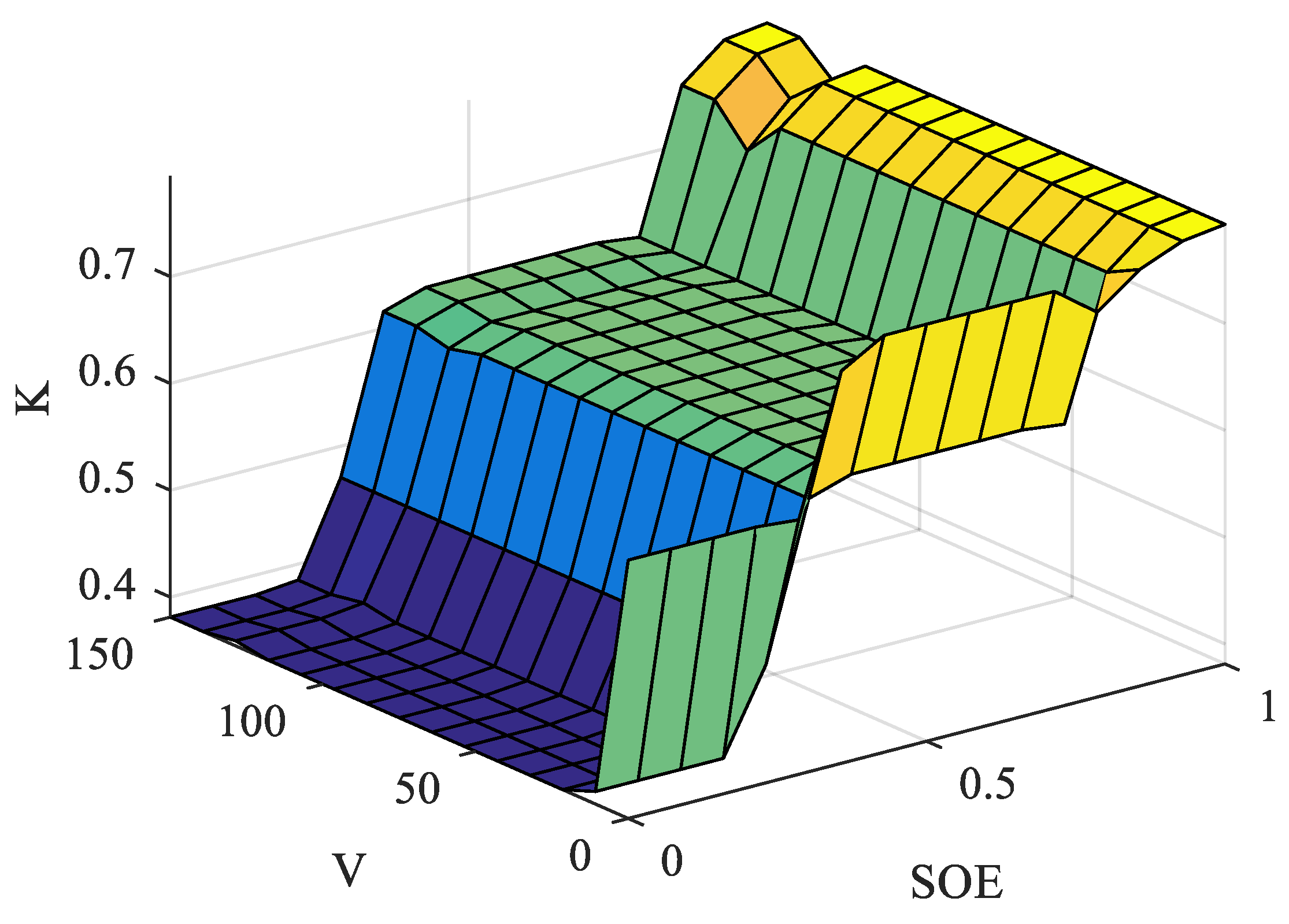
4.2. Design of Fuzzy Controller for Regenerative Braking Torque Distribution

As shown in Figure 9, the braking force allocated to the rear axle is determined by the priority recovery of braking energy, and the regenerative braking force of the motor is precisely regulated and controlled by the fuzzy controller for the electromechanical flywheel system of the front axle. For controlling the regenerative braking force of the motor, the SOE of the flywheel is a very critical factor, which not only affects the safety of the system, but also has a crucial impact on the braking energy recovery efficiency of the system. When the SOC of the battery is higher than 0.8, the high-power charging efficiency of the battery is low, and the damage is large. The pure electric vehicle usually does not recover the braking energy at this time, but the vehicle with the electromechanical flywheel system can make the electromechanical flywheel recover most of it. It not only recovers the braking energy and provides a regenerative braking force, but also protects the power battery. The vehicle speed is used as the input variable of the fuzzy control to control the speed of the flywheel, so as to prevent the flywheel speed from rising too fast under the condition of high vehicle speeds. The electromechanical flywheel system cannot participate in the braking in the second half, and the control motor cannot recover the braking energy. As a consequence, the braking energy recovery efficiency decreased.
The inputs of the fuzzy controller are flywheel SOE, battery SOC, and vehicle speed V, respectively, and the output is the ratio of the regenerative braking force to the total braking force of the front axle. The rear axle is a single drive motor. In order to obtain a higher braking energy recovery efficiency, the series braking energy recovery method is adopted. Finally, the regenerative braking force and mechanical braking force of the front and rear axles are obtained by calculation. The three inputs of the front axle regenerative braking force fuzzy controller are battery SOC, flywheel SOE, and vehicle speed V, and the single output is the regenerative braking force coefficient Kr. Among them, the domain of battery SOC is [0 1], and the fuzzy set of input quantities is SOC = {L M B}. The domain of flywheel SOE is [0 1], and the fuzzy set of input quantities is SOE = {L ML MB B}. The domain of vehicle speed V is [0 150], and the fuzzy set of input quantities is V = {L M B}. The domain of regenerative braking force distribution coefficient Kr is [0 1], and the fuzzy set of output quantities is K = {L ML M MB B}. Among them, L, ML, M, MB, and B represent small, medium-small, medium, medium-large, and large, respectively. In order to control the regenerative braking force more accurately, the fuzzy set of flywheel SOE and regenerative braking force output is divided in more detail, as shown in Table 3.

5. Hardware in the Loop Test and Performance Analysis

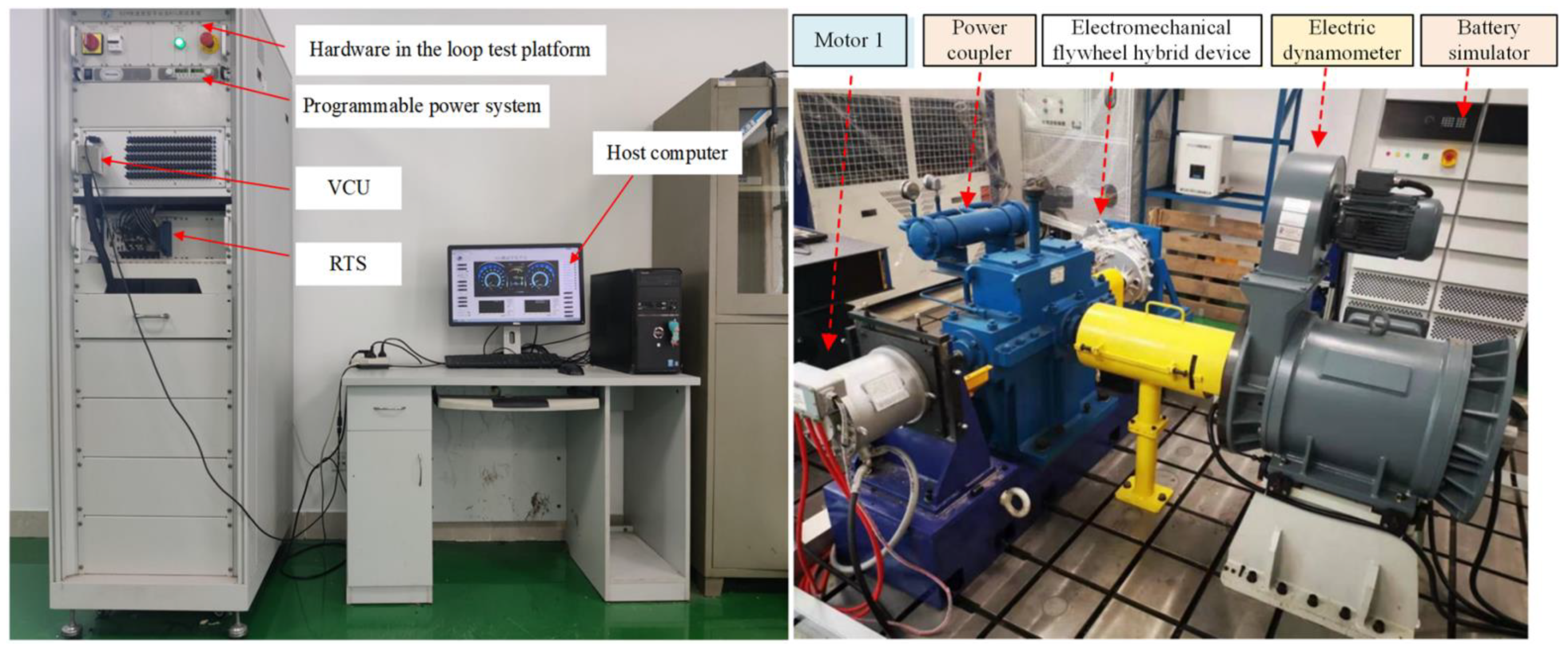
5.1. Test Platform Design

As shown in Figure 10, this is the electromechanical flywheel hybrid system test platform. The hardware in the loop test platform mainly uses the compilation and speed-regulation energy management strategy to generate the executable code of the controller for the electromechanical flywheel hybrid system test platform. The hardware in the loop test platform mainly consists of a host computer, real-time simulator, the vehicle controller, fault calibration board, and so on. Among them, the real-time simulator is designed to run the driver, motor, battery, and other models in real time, output the reference signal required by the control strategy to the vehicle VCU, and update the vehicle and component state parameters in real time according to the control strategy output signal fed back by VCU. The electromechanical flywheel hybrid system test platform consists of motor 1, electromechanical flywheel device, electric dynamometer, power coupler, and battery simulator. Among them, motor 1 is the main drive motor for the electromechanical flywheel hybrid vehicle. The electric dynamometer is controlled by the host computer and can calculate and apply the driving resistance of the whole vehicle in real time. The battery simulator can simulate the charging and discharging characteristics of the lithium-ion battery in the actual running process of the electromechanical flywheel hybrid vehicle through the control of the host computer, and the simulation accuracy is within 3%.

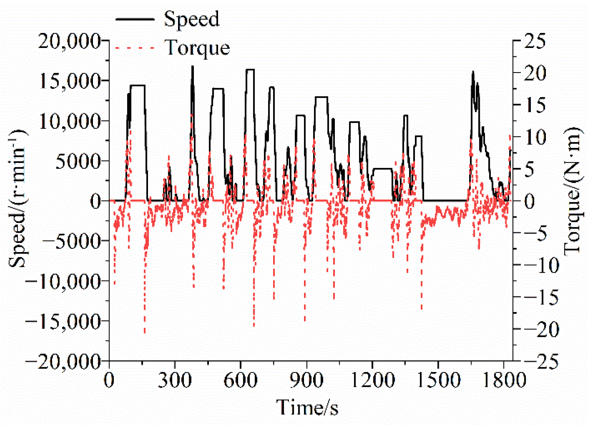
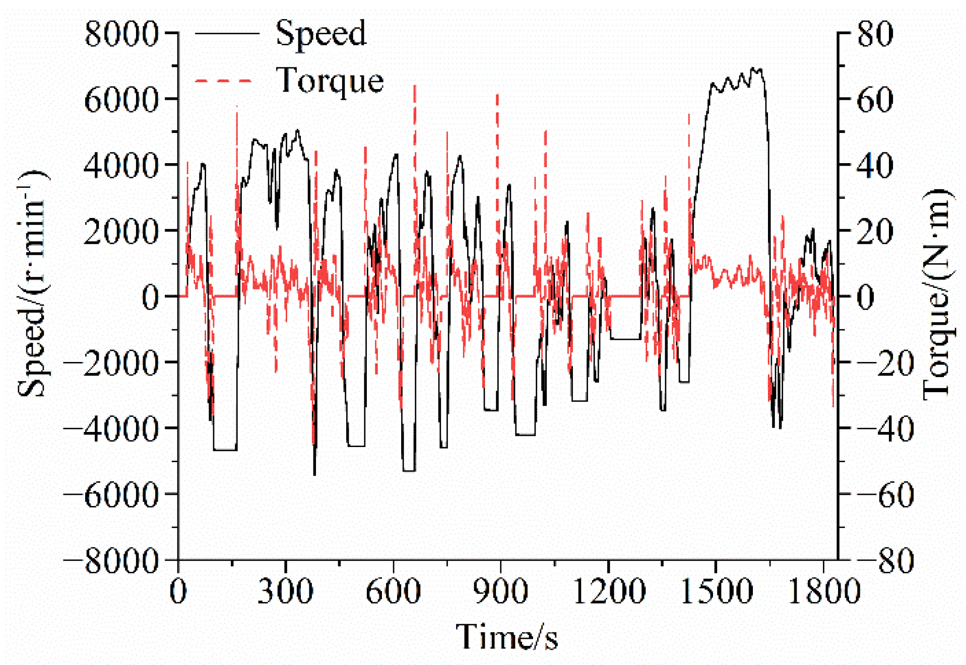
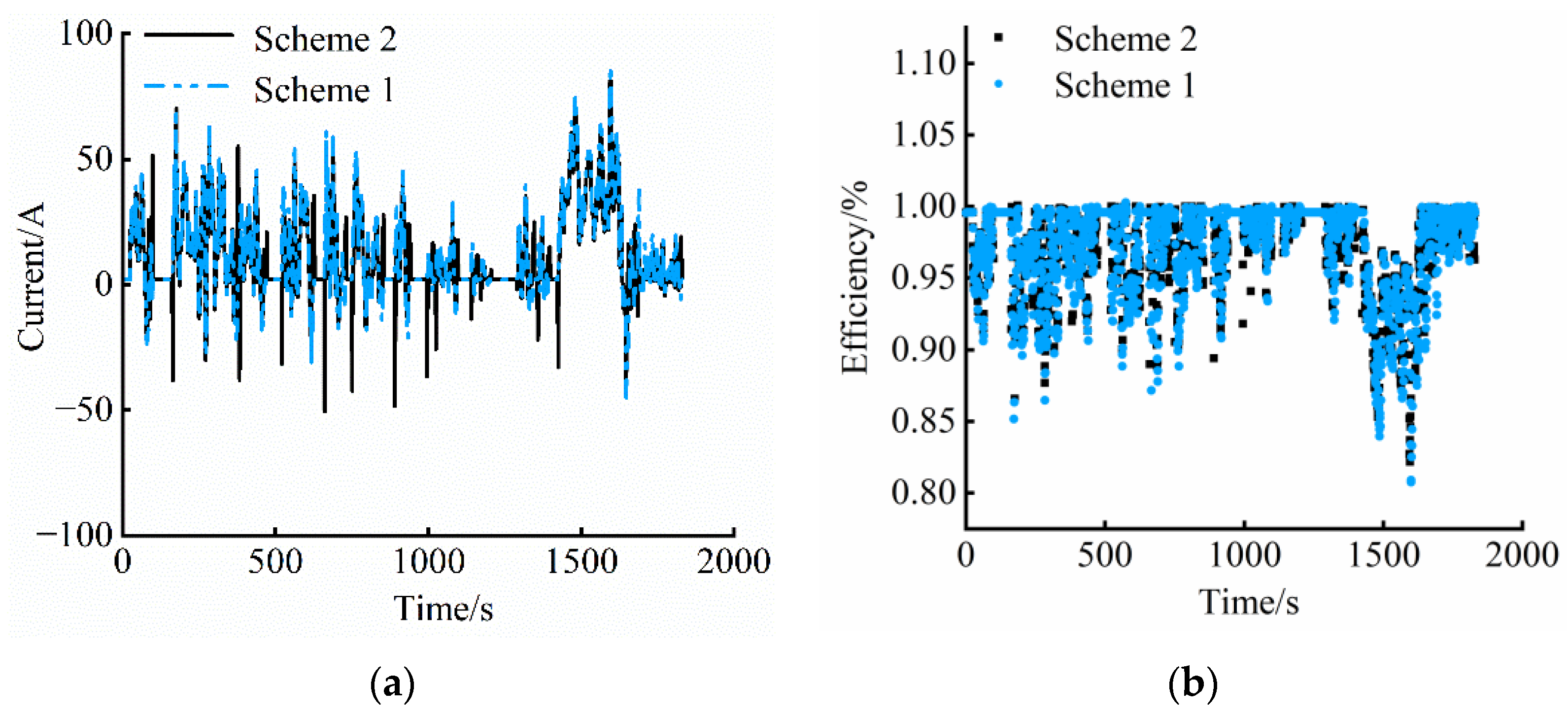
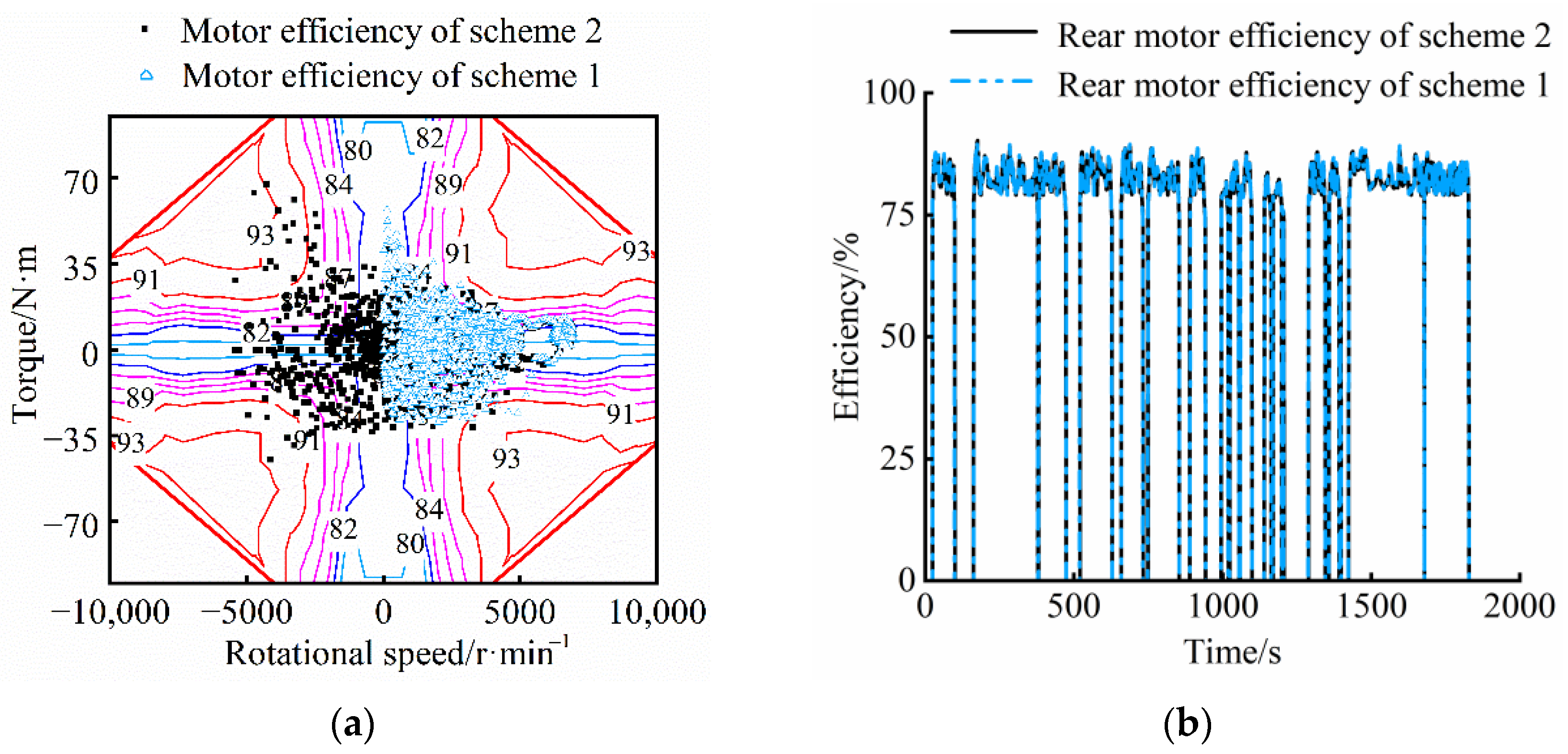
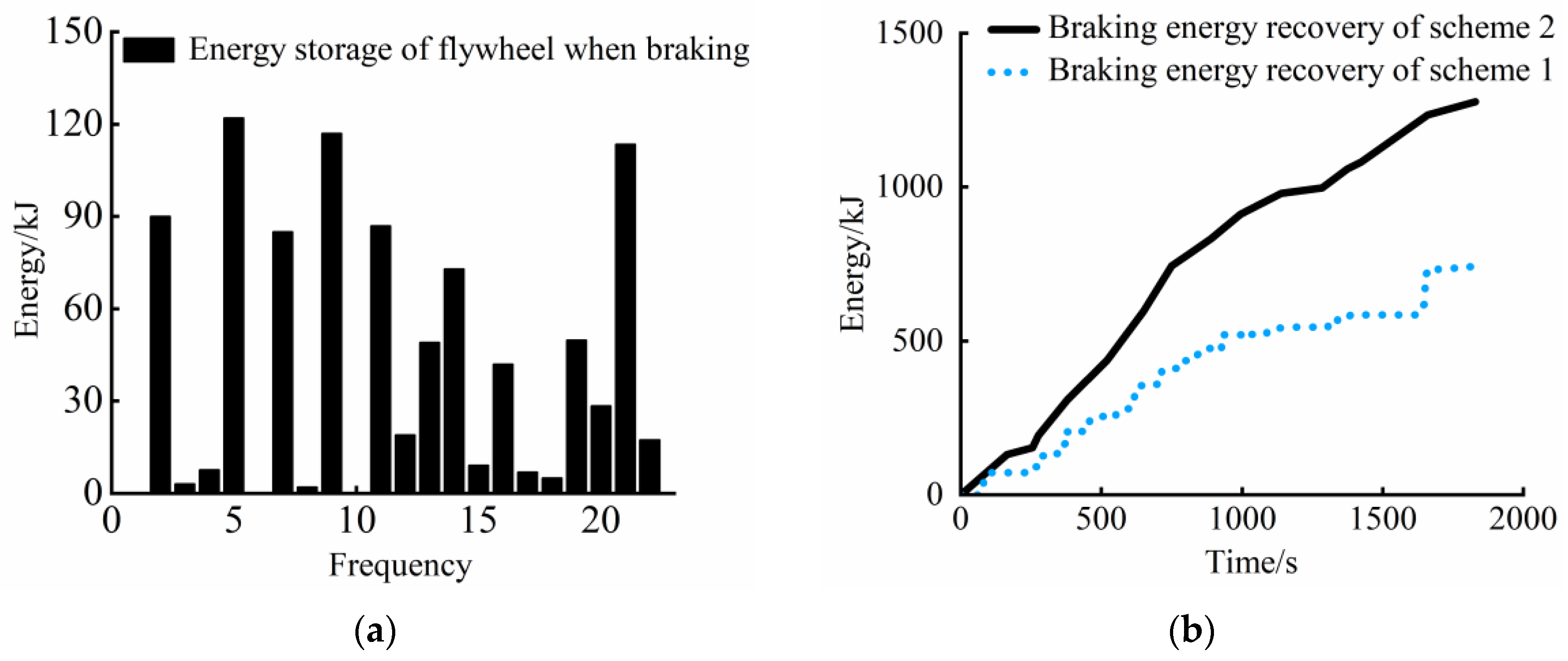
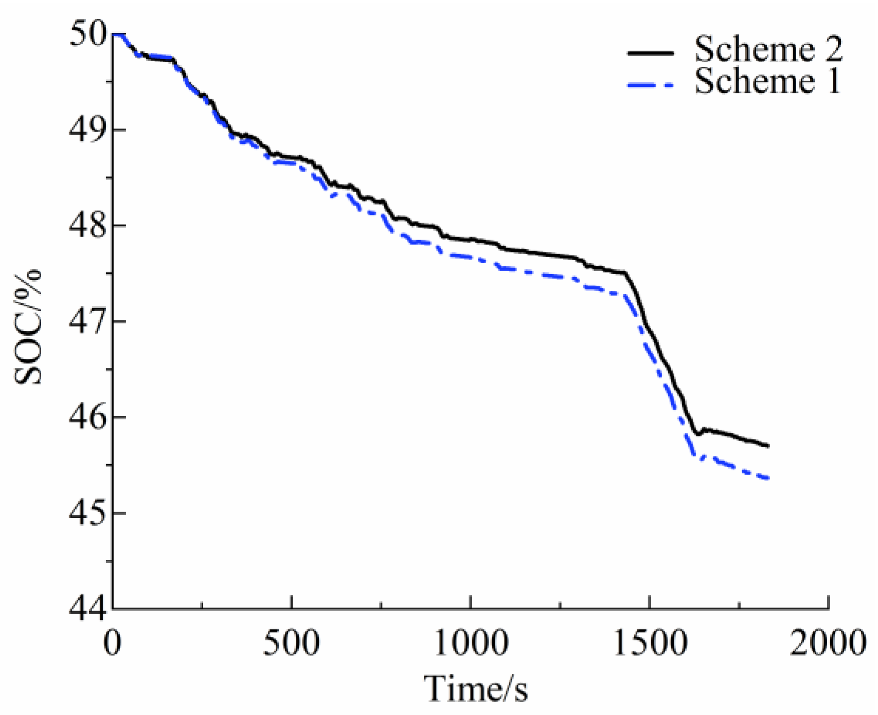
5.2. Analysis of Speed and Torque Laws in Electromechanical Flywheel Hybrid Systems

Taking Japan URBAN as an example, the electromechanical flywheel hybrid system is tested. Figure 11 shows the variation law of flywheel speed and torque under Japan URBAN conditions. Positive torque means that the flywheel participates in braking energy recovery, and the flywheel uses the braking energy to increase the speed. Negative torque means that the flywheel participates in the driving of the whole vehicle, the flywheel outputs kinetic energy to the outside, and the speed decreases. The results show that the proportion of working conditions in which the flywheel participates in the driving of the whole vehicle during the driving process is 9.31%. During the braking process, the proportion of working conditions in which the flywheel participates in the braking of the whole vehicle is 53.24%. After the flywheel participates in regenerative braking energy recovery, its rotational speed is mainly concentrated in the range of 13,000 rpm to 17,000 rpm. Within the above speed range, the braking energy stored by the flywheel can reach 65–85% of the maximum design energy storage.
Figure 12 shows the variation laws for the speed and torque of the speed-regulating motor under Japan URBAN conditions. When the vehicle accelerates, the speed-regulating motor outputs positive torque, which is coupled with the flywheel torque through the planetary gear mechanism to jointly drive the vehicle, and the motor speed increases. When the vehicle is braked, the speed-regulating motor outputs negative torque, and part of it is shunted to the flywheel through the planetary gear mechanism to increase the flywheel speed, and part of it is shunted to the output end to reduce the vehicle speed. In the working condition of the Japan URBAN cycle, there is no condition where the speed-regulating motor stops braking energy recovery due to the high flywheel speed, indicating that the designed energy management strategy is reasonable. During the braking process, the proportion of working conditions where the speed-regulating motor participates in the braking is 11.23%, which helps to improve the economy of the whole vehicle.

5.3. Economic Analysis of Electromechanical Flywheel Hybrid Electric Vehicles

We compared the original dual-motor four-wheel drive scheme with the newly proposed electromechanical flywheel scheme to analyze the impact of the electromechanical flywheel system on vehicle economy. Scheme 1 is a dual-motor four-wheel drive scheme, and scheme 2 is an electromechanical flywheel hybrid four-wheel drive scheme, which was obtained by adding a set of electromechanical flywheel systems on the basis of the original four-wheel drive electric vehicle. The specifications of the main components in the two drive schemes are shown in Table 4.
Figure 13 shows the current and efficiency variation characteristics of the on-board lithium battery under the two driving schemes. Scheme 1 is a dual-motor four-wheel drive scheme, and scheme 2 is an electromechanical flywheel hybrid four-wheel drive scheme. The results show that, compared with scheme 1, scheme 2 uses the flywheel to participate in vehicle driving and braking instantaneously; the peak current of the lithium battery dropped from 87.14 A in scheme 1 to 81.65 A in scheme 2, a reduction by 6.31%; and the average current is reduced by 32.23%, and moreover, the fluctuation range of the current under cycle conditions is reduced by 43.16%. When the car is driving normally or accelerating, if the flywheel has a speed to output work, the power output is the motor and flywheel coupling output. At this time, the drive motor only needs to provide the insufficient part of the total demand power, which will be less than that of the pure electric vehicle without the flywheel system. Therefore, under the same power demand, the output current of the battery in the electromechanical flywheel hybrid scheme is lower than that in the pure electric four-wheel drive scheme. Therefore, compared with scheme 1, scheme 2 can increase the peak efficiency of lithium batteries by 1.78% and the average efficiency by 1.04%, with the advantage of the flywheel participating in energy output and energy recovery. In addition, under the same test conditions, the energy output and recovery of the two schemes are not synchronized. As shown in Figure 13, at the test operating point of 550 s, the battery current of scheme 2 is negative, indicating that there is energy recovery at this time. Under the same operating conditions, the current of Scheme 1 is a positive number, indicating that the battery outputs energy to drive the vehicle at this time. The main reason for the above phenomenon is that under the influence of the flywheel speed, the speed-regulating motor operates in the second quadrant, outputs negative speed and positive torque, and drives the vehicle to accelerate.
Figure 14 shows the efficiency changes of the front drive and rear drive systems under the two schemes. The results show that, compared with scheme 1, scheme 2 uses an electromechanical flywheel as the front drive system, and the average efficiency of the device is increased by 2.41%. The main reason is that the four-quadrant operation of the speed-regulating motor can be realized by using the advantages of the speed-regulating control and power diversion of the planetary gear mechanism. Especially in the second and third quadrants, the average speed motor efficiency compared to the first and fourth quadrants improved by 3.76%. The front drive motor of scheme 1 can only operate in the first and fourth quadrants. By comparing the rear-drive system efficiency distribution under the two schemes, it can be found that the efficiency difference between the two schemes is very small. This is mainly because the motors designed for the rear drive systems of scheme 1 and scheme 2 are of the same type and the same power class.
Figure 15 shows the changes in vehicles’ braking energy recovery under the two schemes. In general, compared with scheme 1, scheme 2 can increase the braking energy recovery of the vehicle by 40.61%. The main reasons are as follows: as shown in Figure 15a, under the Japan URBAN working conditions, the variation in energy storage when the flywheel participates in the braking of the whole vehicle each time. With the advantage that flywheels can recover the braking energy of the vehicle, the maximum cumulative energy storage of flywheels in a single time increases to 117.04 kJ, and the total energy storage of flywheels in the cycling condition increases to 887.4 kJ. However, there is a problem that needs to be noted, that being that the improvement in the total energy storage in the flywheel cycling condition is actually composed of two parts: one is the braking energy recovery from the vehicle, accounting for 82.65%; the other is that when the vehicle braked, the speed-regulating motor works in the motor state after reaching a negative speed through the null point. Due to the dynamic constraints of the planetary gear mechanism, the flywheel still works in the acceleration mode. At this time, part of the energy stored by the flywheel comes from lithium battery energy, accounting for 17.35%.
As shown in Figure 16, the state of charge (SOC) changes of the lithium battery under the two schemes are given under the Japan URBAN condition. The initial SOC setting for the test is 50%. Under scheme 1, SOC decreased from 50% to 45.70%, under Scheme 2, it decreased from 50% to 45.37%, and the total power consumption of the lithium battery decreased by 1.82 %. On the one hand, the flywheel braking recovery energy and output energy are transmitted through mechanical energy, unlike the four-wheel drive electric vehicle recovery and output, which also need to go through the mechanical energy-electric energy conversion, so the efficiency is higher. On the other hand, the flywheel rotates at a certain speed after recovering energy. Due to the speed regulation of the planetary gear mechanism, the motor can be ensured to work as much as possible in the high-efficiency range of medium speed. These factors will help reduce battery energy consumption.

6. Conclusions

In this paper, an electromechanical flywheel hybrid four-wheel drive scheme is proposed to solve the problems of difficult decoupling between vehicle battery efficiency and vehicle working conditions and the low recovery rate of braking energy of dual-motor four-wheel drive electric vehicles. Based on the dynamic characteristics of the planetary gear mechanism, the working mode of the electromechanical flywheel hybrid system is analyzed and designed. On this basis, a driving and braking energy management strategy based on fuzzy rules is formulated. Finally, the loop and system bench tests with the hardware are carried out. The experimental results show that the proportion of flywheel in the driving and braking process is 9.31% and 53.24%, respectively, under the Japan urban conditions. The braking energy stored by the flywheel can reach 65–85% of the maximum design energy storage value. Compared with the dual-motor four-wheel drive scheme, the electromechanical flywheel hybrid four-wheel drive scheme has advantages in terms of flywheel energy output and input adjustment. Therefore, compared with the original dual-motor four-wheel drive scheme, the electromechanical flywheel hybrid four-wheel drive system scheme developed in this paper can reduce the current variation range of lithium batteries by 43.16%, increase the average efficiency by 1.04%, and increase the braking energy recovery rate by 40.61% under the Japan urban cycle conditions. In addition, taking advantage of the energy and power regulation advantages of the electromechanical flywheel device, the power consumption of the lithium battery is reduced by 1.82% under the above cycle conditions. Based on the technical scheme in this paper, the economy of electric vehicles is effectively improved.

Author Contributions

Conceptualization, P.W. and B.S.; data curation, T.G.; formal analysis, P.W.; funding acquisition, S.G.; investigation, P.W., T.G., M.X. and X.Z.; methodology, P.W.; project administration, B.S. and S.G.; resources, B.S. and S.G.; software, T.G.; supervision, S.G.; validation, X.Z.; visualization, M.X. and X.Z.; writing—original draft, P.W.; writing—review and editing, T.G. All authors have read and agreed to the published version of the manuscript.

Funding

This work was supported in part by the Innovation team project for the “Qing-Chuang science and technology plan” involving colleges and universities in Shandong Province 2021KJ083, the National Natural Science Foundation Project of China under Grant 52102465, the key R&D projects in Shandong under Grant 2019GHZ016, the Major Innovation Projects in Shandong under Grant 2020CXGC010405 and 2020CXGC010406, the Postdoctoral Science Foundation of China and Shandong under Grant 2020M680091 and 202003042.

Institutional Review Board Statement

Not applicable.

Informed Consent Statement

Not applicable.

Data Availability Statement

Not applicable.

Conflicts of Interest

The authors declare no conflict of interest.

References

  1. Cao, J.; Chen, X.; Qiu, R.; Hou, S. Electric vehicle industry sustainable development with a stakeholder engagement system. Technol. Soc. 2021, 67, 101771. [Google Scholar] [CrossRef]
  2. Xia, X.N.; Li, P.W. A review of the life cycle assessment of electric vehicles: Considering the influence of batteries. Sci. Total Environ. 2022, 814, 152870. [Google Scholar] [CrossRef] [PubMed]
  3. Sendek-Matysiak, E. Assessment of BEVs Use in Urban Environment. Adv. Intell. Syst. Comput. 2020, 1091, 52–63. [Google Scholar]
  4. Lebrouhi, B.; Khattari, Y.; Lamrani, B.; Maaroufi, M.; Zeraouli, Y.; Kousksou, T. Key challenges for a large-scale development of battery electric vehicles: A comprehensive review. J. Energy Storage 2021, 44, 103273. [Google Scholar] [CrossRef]
  5. Ziegler, D.; Abdelkafi, N. Business models for electric vehicles: Literature review and key insights. J. Clean. Prod. 2022, 330, 129803. [Google Scholar] [CrossRef]
  6. Yadlapalli, R.T.; Kotapati, A.; Kandipati, R.; Koritala, C.S. A review on energy efficient technologies for electric vehicle applications. J. Energy Storage 2022, 50, 104212. [Google Scholar] [CrossRef]
  7. Ehsani, M.; Gao, Y.; Emadi, A. Modern Electric, Hybrid Electric, and Fuel Cell Vehicles: Fundamentals, Theory, and Design; CRC Press: Boca Raton, FL, USA, 2017. [Google Scholar]
  8. Ma, S.C.; Xu, J.H.; Fan, Y. Characteristics and key trends of global electric vehicle technology development: A multi-method patent analysis. J. Clean. Prod. 2022, 338, 130502. [Google Scholar] [CrossRef]
  9. Sun, B.B.; Gao, S.; Ma, C. System Power Loss Optimization of Electric Vehicle Driven by Front and Rear Induction Motors. Int. J. Automot. Technol. 2018, 19, 121–134. [Google Scholar] [CrossRef]
  10. Li, Z.; Khajepour, A.; Song, J. A comprehensive review of the key technologies for pure electric vehicles. Energy 2019, 182, 824–839. [Google Scholar] [CrossRef]
  11. Itani, K.; De Bernardinis, A.; Khatir, Z.; Jammal, A. Comparative analysis of two hybrid energy storage systems used in a two front wheel driven electric vehicle during extreme start-up and regenerative braking operations. Energy Convers. Manag. 2017, 144, 69–87. [Google Scholar] [CrossRef]
  12. Gao, S.; Wu, Z.; Sun, B. Parameters design and economy study of an electric vehicle with powertrain systems in front and rear axle. Int. J. Eng. Trans. A Basics 2016, 29, 454–463. [Google Scholar]
  13. Arani, A.K.; Karami, H.; Gharehpetian, G.; Hejazi, M. Review of flywheel energy storage systems structures and applications in power systems and microgrids. Renew. Sustain. Energy Rev. 2017, 69, 9–18. [Google Scholar] [CrossRef]
  14. Choudhury, S. Flywheel energy storage systems: A critical review on technologies, applications, and future prospects. Int. Trans. Electr. Energy Syst. 2021, 31, e13024. [Google Scholar] [CrossRef]
  15. Dhand, A.; Pullen, K. Review of Battery Electric Vehicle Propulsion Systems Incorporating Flywheel Energy Storge. Int. J. Automot. Technol. 2015, 16, 487–500. [Google Scholar] [CrossRef]
  16. Hansen, J.G.R.; O’Kain, D.U. An Assessment of Flywheel High Power Energy Storage Technology for Hybrid Vehicles; Oak Ridge National Laboratory: Oak Ridge, TN, USA, 2012. [Google Scholar]
  17. Huang, C.N.; Chen, Y.S. Design of magnetic flywheel control for performance improvement of fuel cells used in vehicles. Energy 2017, 118, 840–852. [Google Scholar] [CrossRef]
  18. Qiu, Y.; Jiang, S. Suppression of low-frequency vibration for rotor-bearing system of flywheel energy storage system. Mech. Syst. Signal Process. 2019, 121, 496–508. [Google Scholar] [CrossRef]
  19. Yuan, X.; Zhang, C.; Hong, G.; Huang, X.; Li, L. Method for evaluating the real-world driving energy consumptions of electric vehicles. Energy 2017, 141, 1955–1968. [Google Scholar] [CrossRef]
  20. Sun, B.; Wang, Y.; Li, W.; Zhang, T.; Li, B.; Ge, W. Driving Control Strategy For Hybrid Energy System Based On Fuel Cell, Lithium Battery and Electric Flywheel Battery. Chinese GWP202112496, 14 September 2021. [Google Scholar]
  21. Wang, Y.; Sun, Z.; Chen, Z. Rule-based energy management strategy of a lithium-ion battery, supercapacitor and PEM fuel cell system. Energy Procedia 2019, 158, 2555–2560. [Google Scholar] [CrossRef]
  22. Rimpas, D.; Kaminaris, S.D.; Aldarraji, I.; Piromalis, D.; Vokas, G.; Papageorgas, P.G.; Tsaramirsis, G. Energy management and storage systems on electric vehicles: A comprehensive review. Mater. Today Proc. 2022, 61, 813–819. [Google Scholar] [CrossRef]
  23. Ganesh, A.H.; Xu, B. A review of reinforcement learning based energy management systems for electrified powertrains: Progress, challenge, and potential solution. Renew. Sustain. Energy Rev. 2022, 154, 111833. [Google Scholar] [CrossRef]
  24. Liu, Y.; Liu, J.; Zhang, Y.; Wu, Y.; Chen, Z.; Ye, M. Rule learning based energy management strategy of fuel cell hybrid vehicles considering multi-objective optimization. Energy 2020, 207, 118212. [Google Scholar] [CrossRef]
  25. Chen, L.; Zhu, F.; Zhang, M.; Huo, Y.; Yin, C.; Peng, H. Design and analysis of an electrical variable transmission for a series-parallel hybrid electric vehicle. IEEE Trans. Veh. Technol. 2011, 60, 2354–2363. [Google Scholar] [CrossRef]
  26. Mashadi, B.; Emadi, S.A.M. Dual-mode power-split transmission for hybrid electric vehicles. IEEE Trans. Veh. Technol. 2010, 59, 3223–3232. [Google Scholar] [CrossRef]
  27. Madhusudhanan, A.K.; Na, X.; Cebon, D. A Computationally Efficient Framework for Modelling Energy Consumption of ICE and Electric Vehicles. Energies 2021, 14, 2031. [Google Scholar] [CrossRef]
  28. Wang, T.; Li, Q.; Wang, X.; Qiu, Y.; Liu, M.; Meng, X.; Li, J.; Chen, W. An optimized energy management strategy for fuel cell hybrid power system based on maximum efficiency range identification. J. Power Sources 2020, 445, 227333. [Google Scholar] [CrossRef]
  29. Wang, C.; Liu, R.; Tang, A. Energy management strategy of hybrid energy storage system for electric vehicles based on genetic algorithm optimization and temperature effect. J. Energy Storage 2022, 51, 104314. [Google Scholar] [CrossRef]
  30. Kim, N.; Cha, S.W.; Peng, H. Optimal equivalent fuel consumption for hybrid electric vehicles. IEEE Trans. Control Syst. Technol. 2012, 20, 817–825. [Google Scholar]
Figure 1. Electromechanical flywheel system vehicle structure.
Sustainability 14 11017 g001
Figure 2. Electromechanical flywheel system at the starting and constant speed stage.
Sustainability 14 11017 g002
Figure 3. Rotational speed of electromechanical flywheel system in the working stage.
Sustainability 14 11017 g003
Figure 4. Electromechanical flywheel system in braking stage.
Sustainability 14 11017 g004
Figure 5. Re-acceleration phase of electromechanical flywheel system.
Sustainability 14 11017 g005
Figure 6. Drive mode fuzzy control structure.
Sustainability 14 11017 g006
Figure 7. Drive fuzzy control surface.
Sustainability 14 11017 g007
Figure 8. Fuzzy control structure for the braking force distribution of front and rear axles.
Sustainability 14 11017 g008
Figure 9. Regenerative braking force control model.
Sustainability 14 11017 g009
Figure 10. Electromechanical flywheel hybrid system test platform.
Sustainability 14 11017 g010
Figure 11. Flywheel speed and torque for Japan URBAN cycle operation.
Sustainability 14 11017 g011
Figure 12. Japan URBAN cycle conditions control motor speed and torque.
Sustainability 14 11017 g012
Figure 13. Battery current and efficiency for two schemes: (a) battery current change and (b) battery efficiency.
Sustainability 14 11017 g013
Figure 14. Comparison of front and rear motor efficiency of two schemes: (a) efficiency of control motor and front motor and (b) efficiency of drive motor.
Sustainability 14 11017 g014
Figure 15. Electromechanical flywheel with total brake recovery energy: (a) energy storage of the flywheel in each brake and (b) the total brake energy recovered by the two schemes.
Sustainability 14 11017 g015
Figure 16. Comparison of battery SOC under Japan URBAN cycle conditions.
Sustainability 14 11017 g016
Table 1. Fuzzy rule of driving torque distribution.
Serial NumberFuzzy Control Rules
1If (SOE is L) and (V is L) then (K is MB)
2If (SOE is L) and (V is M) then (K is ML)
3If (SOE is L) and (V is B) then (K is ML)
4If (SOE is M) and (V is L) then (K is B)
5If (SOE is M) and (V is M) then (K is MB)
6If (SOE is M) and (V is B) then (K is MB)
7If (SOE is B) and (V is L) then (K is B)
8If (SOE is B) and (V is M) then (K is B)
9If (SOE is B) and (V is B) then (K is B)
Table 2. Fuzzy rules for the torque distribution of the front and rear axles.
Serial NumberFuzzy Control Rules
1If (FWSOE is L) and (Z is L) then (Kf is B)
2If (FWSOE is L) and (Z is M) then (Kf is MB)
3If (FWSOE is L) and (Z is B) then (Kf is MB)
4If (FWSOE is M) and (Z is L) then (Kf is MB)
5If (FWSOE is M) and (Z is M) then (Kf is MB)
6If (FWSOE is M) and (Z is B) then (Kf is MB)
7If (FWSOE is B) and (Z is L) then (Kf is L)
8If (FWSOE is B) and (Z is M) then (Kf is ML)
9If (FWSOE is B) and (Z is B) then (Kf is B)
Table 3. Regenerative braking force fuzzy control rules.
Serial NumberFuzzy Control Rules
1If (SOC is L) and (SOE is L) and (V is L) then (Kr is B)
2If (SOC is L) and (SOE is L) and (V is M) then (Kr is B)
3If (SOC is L) and (SOE is L) and (V is B) then (Kr is B)
4If (SOC is L) and (SOE is ML) and (V is L) then (Kr is B)
5If (SOC is L) and (SOE is ML) and (V is M) then (Kr is B)
6If (SOC is L) and (SOE is ML) and (V is B) then (Kr is MB)
7If (SOC is L) and (SOE is MB) and (V is L) then (Kr is B)
8If (SOC is L) and (SOE is MB) and (V is M) then (Kr is MB)
9If (SOC is L) and (SOE is MB) and (V is B) then (Kr is M)
10If (SOC is L) and (SOE is B) and (V is L) then (Kr is M)
11If (SOC is L) and (SOE is B) and (V is M) then (Kr is ML)
12If (SOC is L) and (SOE is B) and (V is M) then (Kr is ML)
13If (SOC is M) and (SOE is L) and (V is L) then (Kr is B)
14If (SOC is M) and (SOE is L) and (V is M) then (Kr is B)
15If (SOC is M) and (SOE is L) and (V is B) then (Kr is B)
16If (SOC is M) and (SOE is ML) and (V is L) then (Kr is B)
17If (SOC is M) and (SOE is ML) and (V is M) then (Kr is MB)
18If (SOC is M) and (SOE is ML) and (V is B) then (Kr is MB)
19If (SOC is M) and (SOE is MB) and (V is L) then (Kr is MB)
20If (SOC is M) and (SOE is MB) and (V is M) then (Kr is M)
21If (SOC is M) and (SOE is MB) and (V is B) then (Kr is ML)
22If (SOC is M) and (SOE is B) and (V is L) then (Kr is ML)
23If (SOC is M) and (SOE is B) and (V is M) then (Kr is ML)
24If (SOC is M) and (SOE is B) and (V is B) then (Kr is L)
25If (SOC is B) and (SOE is L) and (V is L) then (Kr is B)
26If (SOC is B) and (SOE is L) and (V is M) then (Kr is B)
27If (SOC is B) and (SOE is L) and (V is B) then (Kr is MB)
28If (SOC is B) and (SOE is ML) and (V is L) then (Kr is MB)
29If (SOC is B) and (SOE is ML) and (V is M) then (Kr is MB)
30If (SOC is B) and (SOE is ML) and (V is B) then (Kr is M)
31If (SOC is B) and (SOE is MB) and (V is L) then (Kr is M)
32If (SOC is B) and (SOE is MB) and (V is M) then (Kr is M)
33If (SOC is B) and (SOE is MB) and (V is B) then (Kr is ML)
34If (SOC is B) and (SOE is B) and (V is L) then (Kr is ML)
35If (SOC is B) and (SOE is B) and (V is M) then (Kr is L)
36If (SOC is B) and (SOE is B) and (V is B) then (Kr is L)
Table 4. The specifications of the main components in the two drive schemes.
ParameterValue
Complete vehicle kerb mass (Scheme 1)1580 kg
Radius of tire (both)300 mm
Rolling resistance coefficient (both)0.015
Air resistance coefficient (both)0.3
Windward area (both)2 m2
Type of drive motorPermanent magnet motor
Rated speed of drive motor (both)3000 rpm
Rated torque of drive motor (both)64 N·m
Rated power of drive motor (both)20 kW
Peak speed of drive motor (both)8000 rpm
Peak torque of drive motor (both)130 N·m
Peak power of drive motor (both)40 kW
Mass of flywheel (Scheme 2)8.8 kg
Height of flywheel (Scheme 2)100 mm
Inner radius of flywheel (Scheme 2)100 mm
Outer radius of flywheel (Scheme 2)150 mm
Speed range of flywheel (Scheme 2)0~20,000 rpm
Rotational inertia of flywheel (Scheme 2)0.08 kg·m2
Type of control motor of flywheelAC induction motor
Rated speed of control motor (Scheme 2)4000 rpm
Rated torque of control motor (Scheme 2)35 N·m
Rated power of control motor (Scheme 2)15 kW
Peak speed of control motor (Scheme 2)10,000 rpm
Peak torque of control motor (Scheme 2)95 N·m
Peak power of control motor (Scheme 2)40 kW
Type of battery packTernary lithium battery
Rated voltage (both)320 V
Rated capacity (both)130 Ah
Rated power (both)100 kW
Publisher’s Note: MDPI stays neutral with regard to jurisdictional claims in published maps and institutional affiliations.

