
Sustainable Development Solutions for the Medical Waste Problem Using Thermal Plasmas
1
Department of Engineering Science, Applied College, Umm Al-Qura University, Makkah 24382, Saudi Arabia
2
Department of Physics, Faculty of Science, Beni-Suef University, Beni Suef 62521, Egypt
Sustainability 2022, 14(17), 11045; https://doi.org/10.3390/su141711045
Submission received: 13 July 2022
/
Revised: 10 August 2022
/
Accepted: 12 August 2022
/
Published: 5 September 2022
(This article belongs to the Special Issue Degradation of Plastics in the Environment)
Abstract
:Waste-to-energy (WTE) conversion is a vital process in the Middle East, especially in the Kingdom of Saudi Arabia (KSA), which is considered sustainable development for the environmental strategic project. Previous publications dealt with the environmentally friendly plasma treatment of wastes such as municipal waste, scrap tire waste, plastic waste, and grey water, using thermal plasmas produced by the cornerstone part of plasma reactors, namely the air plasma torch. In the present paper, with a view to energy recovery from medical waste, the thermodynamic properties of air plasma torches with a flow rate of air ranging from 10 mg/s to 30 mg/s and plasma jet temperatures ranging from 1500 °C to 5000 °C were investigated; these include power loss, enthalpy, plasma flux, and torch efficiency variation with plasma input power and air flow rate. The measured electrothermal efficiency of the plasma torch is in the range of 42% to 80% and increases with the increasing input power and gas flow rate. In Makkah, the number of beds in the hospitals is 10,500; the average annual weight of the medical waste in the hospitals is 2835 × 103 t, with an extracted amount of pyrolysis oil equivalent to 2268 × 103 t and an equivalent energy of 90 × 109 M J. In the proposed plasma treatment project, the amount of diesel oil after the distillation process will reach up to 1928 × 103 t, with an estimated sale profit of the electricity reaching up to 21 × 106 MW·h. The sale profit of pyrolysis oil in 2022 reaches up to USD 34.44 million, and the sale profit of electricity extracted by using the diesel oil in 2022 reaches up to USD 1020 million for households and USD 1445 million for factories.
1. Introduction
Until 1879, people thought that there were only three states of matter (the solid, liquid, and gaseous states) in the universe, but then, William Crookes, Joseph Thompson, and Irving Langmuir discovered the properties and the nature of the fourth state of matter, which they called plasma. Plasma is a quasi-neutral ensemble of positively and negatively charged particles and neutral particles, featuring a collective behavior. Plasma can be formed in different ways, but the most common way is electric discharge. Applying an electrical voltage leads to the breakdown of the gas and its ionization. Plasmas are generally divided into two large groups. The first is the cold, non-thermal or non-equilibrium plasma, which was studied in our previous articles for applications such as etching for industrial applications [1,2], disinfection applications [3,4], environmental process, textile treatment [5,6], and nano-technology applications [7]. The second group is the hot, thermal or equilibrium plasma used in many applications which were studied and outlined in our previous articles on using the plasma treatment system (PST) to convert waste to energy (WTE) using, e.g., municipal solid waste (MSW) and scrap tires [8,9].
Thermal plasma produced in a plasma torch has helped the development of industrial applications at very high temperatures and degrees of conversion due to its high energy density and fast processes and low emissions in comparison with the conventional methods. In these plasma reactors, organic compounds are decomposed at very high and fast degrees of conversion, whereby the waste is converted into different energy products, such as syngas, synthetic fuels, hydrocarbons, biofuel, carbon black, and electricity [10,11].
The plasma gasification reactor to obtain energy recovery from different types of medical waste is based on our previous stages of the plasma treatment projects (PTP) in Makkah in the seasons of the pilgrims: (i) the plasma treatment project for municipal solid waste to energy (PTPMSW) [12], from waste sources or from landfill with a view to their sustainable energetic or chemical valorization and the product gas efficiency of waste to gas. The electrical power generation system for the plasma treatment process required was estimated at 5000 kW: 2000 kW for the operation of the system and 3000 kW sold. The second was the (ii) plasma treatment project for scrap tires (PTPST) [13] to produce synthetic fuels and syngas, hydrocarbons, biofuels, and carbon black. The main products are 40% slag, 8% synthetic syngas, and 52% pyrolysis oil. Annually in Makkah, after treatment by plasma, the heat energy extracted from scrap tires is 15.5 TJ per ton.
Huge quantities of medical waste are collected every day from the hospitals, health-care units, and maternity and nursing homes in Makkah. Medical waste is considered to be environmentally hazardous, dangerous, and highly infectious because of possible contamination with pathogenic micro-organisms. According to official KSA reports, hospitals in Makkah contain 10,500 beds, and each bed generates 750 g/day of medical waste [14,15,16,17].
There are many categories of medical waste in these hospitals, such as chemical waste, infectious waste, and radioactive waste, and the majority contain different types of plastics, such as plastic pallets, plastic drums, plastic buckets, plastic film, waste appliances shell, plastic garbage drums, IBC drums, IBC barrels, garbage bags, rubbish bags, and plastic pipes. The plastics are classified as follows: HDPE (high-density polyethylene), PVC (polyvinyl chloride), PET (polyethylene terephthalate), LDPE (low-density polyethylene), (PS) polystyrene, and miscellaneous plastics [18,19].
The proposed plasma gasification process for Makkah will be considered as an energy recovery transition process for medical waste and an environmentally friendly technology because in comparison to conventional technologies it converts organic waste pollutants into commercially useful products. Thermal plasma treatment provides a faster destruction process of the plasma jet emerging from the plasma torch, high-value energy products (syngas, pyrolysis oil, and slag), high profit, and a low production of pollutants. In the present article, another target is to study the characteristics of the emerging plasma jet required for the plasma gasification of medical waste. Moreover, it is to study the conversion process of medical waste into fuel oil as well as the environmental and economic aspects. Furthermore, energy recovery and the profit from the sale of the produced electricity are analyzed.
The experimental set-up to test and validate the plasma treatment of the medical waste is described in Section 2. Section 3 presents the characteristics of the plasma jet exciting the plasma torch and the production of pyrolysis oil, diesel, and electricity. Finally, the conclusions and outlook are given in Section 4.
2. Experimental Set-Up and Procedures
2.1. Plasma Torch
The air torch is shown in Figure 1. It is powered by direct current, and it is considered as the main component of the plasma furnace. In our previous article [20], a brief discussion of the air torch’s schematic diagram (non-transferred arc) is provided. The plasma torch’s characteristics, which are listed in Table 1, make it possible to create a plasma jet that is both compatible with waste-to-energy operations and easily adjustable for the conversion of electrical energy into the thermal energy needed for various environmentally friendly processes.
An electrical discharge is generated between the electrodes; the cathode and the anode are large enough to resist gradual erosion, considering the water cooling to handle the high temperatures. In the plasma torch, electrical energy is converted into heat, and a thermal plasma jet is ejected from the torch due to the pressure of the compressed air flow when it passes between the gas column and the surface of the inner anode [21,22].
The flow rate of the reaction gas is detected using a Pitot tube flow meter, while the temperature at the reactor’s inner wall and the temperature of the gas are measured using thermocouples. The air flow rate varies between 10 mg/s and 30 mg/s, and the high-temperature plasma of the jet at the nozzle of the torch significantly impacts the oxidation in the plasma treatment reactor for the current investigation (present study) [23]. The operating characteristics of the air torches are presented. In Section 3, the operating characteristics of the air plasma torch are presented, such as the applied power, the applied flow rate, the torch efficiency variation, and the characteristics of the emerging jet (mean temperatures, velocity, radiation wavelength, power loss, enthalpy, and plasma flux).
The enthalpy probe is a device commonly used in experiments [12,13,24]. The advantages are that it is a low-cost appliance, and the velocity and enthalpy of the plasma can be measured directly. The disadvantage is that it may perturb the plasma. Experiments have shown that the plasma is only cooled down about 3% in the centerline by inserting the enthalpy probe. This error is comparable with that found in other techniques, such as emission spectroscopy. It was found that the enthalpy probe is accurate for temperatures up to 10,000 K and even more accurate than emission spectroscopy.
The enthalpy probe consists of three concentric tubes and is water-cooled. The probe measures the stagnation pressure and takes gas samples. There are three thermocouples present. One measures the temperature of the gas at the probe end, and the two others measure the temperature rise in the cooling water The local specific enthalpy of the plasma htip can be derived from the combined energy balance of the cooling-water flow and the gas sample. The plasma enthalpy can be given by the following Equation (1) [25]:
htip is the enthalpy at the tip of the probe, and hexit is the enthalpy at the exit of the probe. ∆TGF is the temperature rise of the cooling water if there is a gas flow, and ∆TNGF is the temperature when there is no gas flow (tare measurement). mwater is the mass flow of the cooling water, mgas is the mass flow of the gas, Cp is the specific heat of the water and is assumed to be constant. The flow of the gas must be in accordance with the isokinetic sampling law. This law states that the velocity in the measuring tube must be as close as possible to the free stream velocity. In this equation, mwater must be altered to make sure the temperature difference (∆TGF − ∆TNGF) is large enough to measure, but it is constant during the measuring cycle [26]. If the mass flow of the gas is increased, the ratio of the mass flows decreases, but the heat flux to the cooling water increases. These two effects cancel each other out; so, the plasma enthalpy is independent of the mass flow of the gas within a certain range. hexit is calculated from the temperature at the exit of the probe and it does not vary significantly with the mass flow. If the gas composition is known at the probe exit, the mass of the gas can be calculated through the mass flow rate. The plasma temperature T can be calculated from the dependency of htip on the temperature [27].
htip = mwater mgas Cp (∆TGF − ∆TNGF) + hexit
2.2. Plasma Gasification Reactor
The plasma treatment project in the present case study stands for: (i) the pre-treatment of medical waste for rapid processing using chopping and grinding processes before feeding it to the plasma treatment reactor. (ii) The conversion process of medical waste into the three products of syngas, pyrolysis oil, and slag occurs in a combustion-like chamber at temperatures as high as 1500 °C and in the presence of the working active gas air, which has a significant impact on oxidation in the plasma treatment reactor without producing environmental contaminants from the produced gases. (iii) The synthesis gas (syngas) is cleaned, the industrial fuel (pyrolysis oil) is gathered, distillated, and purified, and the slag is occasionally or continuously tapped out at the reactor’s bottom [28].
The experimental reactor for the treatment of medical waste is shown in Figure 2. The inner surface of the reactor is covered with a layer of thermal ceramics and acts as an insulating layer with a thickness of 400 mm to reduce energy loss to the outer walls. To prevent the destruction of the ceramic insulation, before carrying out the experiments, the reactor is pre-heated for 24 h to about 1500 °C and, in addition, by a plasma torch at a power level of 125 kW. All parts of the reactor chamber are cooled with water, and calorimetry measurements are made on the cooling circuits. The medical plastic waste to be treated is continuously supplied, and the feeding rate is controlled.
3. Results and Discussion
3.1. Plasma Jet Characteristics
Plasma is usually generated in an electric arc by running a current through a gas or a vacuum, whereby a conducting path is formed between the electrodes; this process is called breakdown.
The mean temperature of the jet is (500–1500) °C at the torch nozzle with an applied power of (25–125) kW. The analysis of the obtained results shows that this plasma technology could be easily employed for environmentally friendly applications, such as the decomposition of scrap tires into their products: carbon, syngas, pyrolysis oil, and slag.
The corresponding jet Length images, with a gas flow rate of G = 10 L/min and 20 L/min and an arc current of I = 100 A, as in Figure 3a,b, show that as the energy supplies increases, the plasma jet length increases. The jet temperature increases and the heat exchange between the plasma jet and the atmosphere also increases. This may be because the plasma jet is in a laminar flow state at a slower gas flow rate. At this state, the jet length increases when the energy supplied to the plasma jet is increased by adjusting the arc length.
When increasing the gas flow rate to Ggas = 30 L/min and 40 L/min and an arc current of I = 100 A, as in Figure 3c,d, the plasma jet entrains more air, which leads to a larger heat loss, and the plasma jet gradually changes from a laminar flow state to a turbulent flow state [29].
The relation between the applied power and the electrothermal efficiency ratio of the plasma torch was investigated as follows [30,31]: is the ability of the plasma torch to convert electric energy into thermal energy. The efficiency depends on several parameters, such as torch design, plasma gas flow rate, the nature of the plasma gas, torch input power, etc. The of the plasma torch can be calculated as in (2)
where Pin and Ploss are the input electrical power flow into the jet (Iampere × Vvolt) and the power loss by the cooling system, respectively. The power loss represented by the dissipated power (heat transfer to electrodes and walls and waste material) due to conduction, convection, and radiation can be calculated according to the following Equation (3)
Neglecting the power loss due to convection and radiation for the plasma torch, Equation (3) can be written as in (4):
Substituting (4) in (2), we obtain (5):
where Cp represents the specific heat of water (kJ/kg K), represents the mass flow rate of the cooling water (kg/s) to prevent the torch from overheating too rapidly, and are the inlet and outlet water temperatures (K), and ΔT = represents the heat losses to the walls and electrodes which are taken away by the cooling water. By using Equation (3), the electrothermal efficiency of the plasma jet (%) as a function of the measured input power (kW), and for the different values of the air flow rate (10–20–30) mg/s, can be plotted as shown in Figure 4, where increases with the increasing input power and is found to be in the range from 80% to 42%, which always increases with the gas flow rate increases because of the high gas flow, which carries more heat out of the torch channel [26,27,28,29].
The different effective parameters of will be measured at the low air flow rate of 10 mg/s.
Equation (2) can be written as follows:
Then, Equation (6) can be written as follows:
By using Equation (6), Figure 5 shows the electrothermal efficiency of the plasma torch for the low air flow rate of 10 mg/s as a function of to give a straight line with negative slope , represented by , where, as increases, the efficiency of the torch will be reduced because of the losses due to the heat transfer to the electrodes and walls (conduction and convection). From Equations (3)–(5), (ΔT) is directly proportional to Pin and Ploss. Figure 6 shows Pin and Ploss for the air flow rate of 10 mg/s as a function of (ΔT). Furthermore, the plasma flux of the jet as a difference between can be calculated as follows:
Figure 7 shows that the plasma flux for the low air flow rate of 10 mg/s is directly proportional to input power with the linearity relation.
As thermal plasma is in local thermodynamic equilibrium (LTE), it may be described as a fluid with specific thermodynamic and transport properties [32,33]. Therefore, heat transfer in thermal plasmas can be described in terms of heat convection, conduction, and radiation [30]; compared with other fluids, thermal plasma is characterized by very high enthalpy (MJ/kg), thermal conductivity, and radiation intensity, and thus, the heat transfer in thermal plasma is extremely high.
At high temperatures, the power losses due to different processes (discussed briefly in Appendix A) increase the heat transfer from the plasma jet [34,35,36].
3.2. Conversion Process and Fuel Type from Medical Waste Treatment
Plasma gasification is considered as an environmentally friendly process to convert medical waste into fuel oil [37,38,39,40]. The proposed plasma treatment system is based on the above-presented characteristics of the plasma torch mounted on a plasma furnace with a capacity of 200 t per day, as schematically shown in Figure 2.
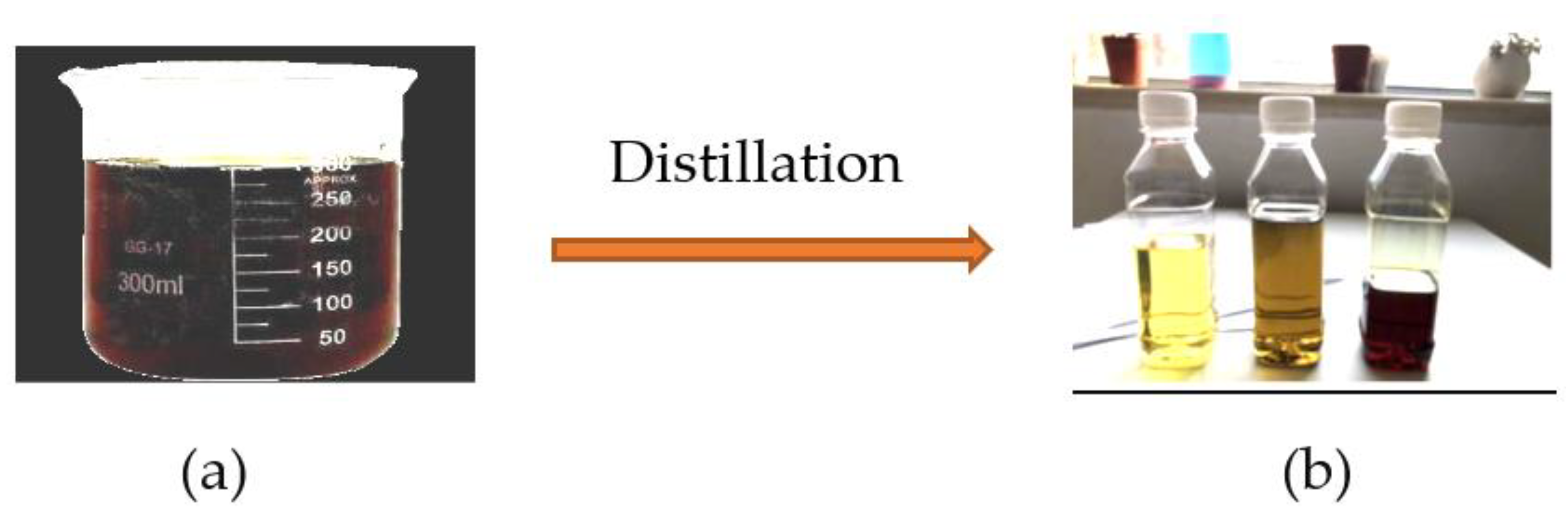
After the quenching process of the hot emerging gas, pyrolysis oil condensates as a fuel oil, but it cannot be used directly as source of energy due to its high ash and wax content, as shown in Figure 8. The collected pyrolysis oil product is very similar to crude oil and is brownish-black and viscous [41,42,43,44], which is an indication that it needs many distillation steps to be a source of hydrocarbons in the form of naphtha products, with characteristics modified with the standard fuel products expected to be used in an engine. The condensation process for the pyrolysis oil at different temperatures gives different types of fuel: (i) gasoline fuel at 500–560 °C; (ii) kerosene fuel at 580 °C and 600 °C; and (iii) diesel oil at 620 °C and 650 °C.
3.2.1. Energy from Pyrolysis Oil
We use the following data from the official KSA reports. Table 2 shows the following annual data for Makkah: (i) the number of beds in the hospitals is 10,500, with an average weight of medical waste per bed of 270 t, and the average weight of medical waste in the hospitals is 2835 × 103 t; and (ii) the amount of pyrolysis oil extracted is 2268 × 103 t with the equivalent energy of 90 × 109 M J of plastic waste [45] using the plasma proposed above; the analysis of the medical plastic waste using the plasma gasification system proposed above [45] shows that fuel oil from the pyrolysis of medical waste plastics is an important source of energy. In this pyrolysis process, the medical plastic waste is decomposed thermochemically using the plasma gasification furnace system at temperatures of up to 1500 °C and converted into fuel oil, slag, and syngas (oil, solid, and gaseous) fractions.
3.2.2. Electricity from Diesel Oil
Table 3 shows the output electricity produced from diesel oil annually, with a lower sulphur and higher cetane value in comparison with traditional diesel, after the distillation process for the pyrolysis oil (where the diesel oil amount reaches to 85% of the pyrolysis oil, as shown in Table 2, as follows: (i) the equivalent diesel oil after the distillation process reaches to 1928 × 103 t, with an extracted sale amount of electricity reaching to 21 × 106 MW·h.
3.3. Economical Vision
The sale profit of pyrolysis oil liters in 2022 reaches to USD 8.61 million, and the sale profit of electricity extracted by using the diesel oil in year 2022 reaches to USD 255 million for households and USD 361 million for factories, as shown in Table 3.
Petroleum [49,50,51,52] is a crucial resource for commercial and large-scale infrastructure and is used in many facets of daily life. When synthetic fuel is made from medical plastic waste that has been processed in a plasma reactor, it gives the equivalent energy and costs less than that taken from petroleum and produces a gross profit, as shown in Table 3.
4. Conclusions and Outlook
The plasma reactor of the thermal plasma treatment system with a flow rate of air ranging from 10 to 30 mg/s into the plasma torch and an electrothermal efficiency in the range from 42% to 80% was analyzed. When the plasma torches operate at low power levels, the temperature increases, and there are losses of power due to the conduction and convection processes. This in turn leads to a faster destruction process and increases the heat transfer to the thermal-treated products, such as grey water, municipal solid waste, and scrap tires.
In Makkah, the average weight of medical waste in hospitals annually is 2835 × 103 t; the extracted amount of pyrolysis oil reaches up to 2268 × 103 t with an equivalent energy 90 × 109 M J; the amount of diesel oil reaches up to 1928 × 103 t.
The estimated sale profit of electricity from the medical waste treatment project reaches up to 21 × 106 MW·h. The sale profit of pyrolysis oil in 2022 reaches up to USD 8.61 million, and the sale profit of electricity extracted by using the diesel oil in 2022 reaches up to USD 255 million for households and USD 361 million for factories.
The perspective is to use the investigated plasma torch in an experimental set-up to test and validate the conversion of slaughterhouse waste in Makkah into useful products.
Funding
The Deanship of Scientific Research at Umm Al-Qura University supported this work by grant (grant code: 22UQU4250206DSR02).
Institutional Review Board Statement
Not applicable.
Informed Consent Statement
Not applicable.
Data Availability Statement
Data are contained within the article.
Acknowledgments
The authors would like to thank the Deanship of Scientific Research at Umm Al-Qura University for supporting this work by grant code: (22UQU4250206DSR02).
Conflicts of Interest
The authors declare no conflict of interest.
Appendix A
The dissipated power (heat transfer to electrodes and walls and waste material) due to) conduction, convection, and radiation can be calculated according to Equation (A1)
Then
where Cp represents the specific heat of water (kJ/kg K), represents the mass flow rate of the cooling water (kg/s) to prevent the torch from overheating too rapidly, and are the inlet and outlet water temperature (K). A is the surface area of the anode (m2), h is the anode–environment convective heat transfer coefficient, Ts is the temperature of the anode surface, Tsur = T∞ = 300 K is the ambient temperature, ε is the emissivity of the anode surface, and σ is the Stefan–Boltzmann constant (5.67 × 10⁻⁸ W/m2⋅K4).
References
- Nasser, E. Fundamentals of Gaseous Ionization and Plasma Electronics; Wiley-Interscience: New York, NY, USA, 1971. [Google Scholar]
- Raizer, Y.P. Gas Discharge Physics, 1st ed.; Allen, J.E., Ed.; Springer: Berlin/Heidelberg, Germany, 1991. [Google Scholar]
- Asghar, A.H.; Ahmed, O.B.; Galaly, A.R. Inactivation of E. coli using atmospheric pressure plasma jet with dry and wet argon discharges. Membranes 2021, 11, 46. [Google Scholar] [CrossRef]
- Asghar, A.; Galaly, A.R. The Effect of oxygen admixture with argon discharges on the impact parameters of atmospheric pressure plasma jet characteristics. Appl. Sci. 2021, 11, 6870. [Google Scholar] [CrossRef]
- Galaly, A.R.; Ahmed, O.B.; Asghar, H.A. Antibacterial effects of combined non-thermal plasma and photocatalytic treatment of culture media in the laminar flow mode. Phys. Fluids 2021, 33, 043604. [Google Scholar] [CrossRef]
- Asghar, A.H.; Galaly, A.R. The Influence of Different Plasma Cell Discharges on the Performance Quality of Surgical Gown Samples. Materials 2021, 14, 4329. [Google Scholar] [CrossRef]
- Galaly, A.R.; Dawood, N. Non-Thermal Plasma Treatment Coupled with a Photocatalyst for Antimicrobial Performance of Ihram Cotton Fabric. Nanomaterials 2022, 12, 1004. [Google Scholar] [CrossRef]
- Galaly, A.R. 16th Treatment of Wastes by Plasma Gasification in Makkah. 2016, pp. 293–319. Available online: https://drive.uqu.edu.sa/_/hajj/files/multaqa/143716.pdf (accessed on 25 May 2016).
- Galaly, A.R. 19th Treatment of Scrap Tires by Plasma Gasification in Makkah. 2019, Volume 19, pp. 294–315. Available online: https://drive.uqu.edu.sa/_/hajj/files/multaqa/143716.pdf (accessed on 12 July 2022).
- Ojha, A.; Reuben, A.C.; Sharma, D. Solid waste management in developing countries through plasma arc gasification. APCBEE Procedia 2012, 1, 193–198. [Google Scholar] [CrossRef]
- Sikhawar, V.; Hrabovsky, M.; Van Oost, G.; Pohořelý, M.; Jeremiáš, M. Progress in waste utilization via thermal plasma. Prog. Energy Combust. Sci. 2020, 81, 100873. [Google Scholar] [CrossRef]
- Galaly, A.R.; van Oost, G. Environmental and economic vision of plasma treatment of waste in Makkah. Plasma Sci. Technol. 2017, 19, 105503. [Google Scholar] [CrossRef]
- Galaly, A.R.; van Oost, G. Environmental and economic aspects of the plasma treatment of scrap tires to produce syngas and synthetic fuels in Saudi Arabia. IEEE Trans. Plasma Sci. 2021, 49, 522–534. [Google Scholar] [CrossRef]
- General Authority for Statistics, Kingdom of Saudi Arabia. 2019. Available online: www.stats.gov.sa/en (accessed on 12 July 2022).
- Ministry of Finance, Kingdom of Saudi Arabia. Report Performance Budget (1985 and 2018). Available online: https://www.mof.gov.sa/en/generalservcies/open-data/Pages/Home.aspx (accessed on 12 July 2022).
- Ministry of Environmental and Water Agriculture, Kingdom of Saudi Arabia. Available online: https://www.scribd.com/document/449567732/6-BAH-MEWA-KSA-NES-CEDA-Executive-Summary-v3-20180221-ENG (accessed on 12 July 2022).
- Department of Statistics. The Statistical Yearbook, No. 50; The Ministry of Economy and Planning: Jeddah, Saudi Arabia, 2018.
- U.S. Environmental Protection Agency. Wastes–Resource Conservation-Common Wastes and Materials–Scrap Tires and Plastic: Basic Introduction. 2014. Available online: https://www.epa.gov/wastes/conserve/materials/tires/basic.htm (accessed on 12 July 2022).
- U.S. Environmental Protection Agency. Advancing Sustainable Materials Management; U.S. Environmental Protection Agency: Washington, DC, USA, 2015.
- Galaly, A.R.; van Oost, G. Fast inactivation of microbes and degradation of organic compounds dissolved in water by thermal plasma. Plasma Sci. Technol. 2018, 20, 085504. [Google Scholar] [CrossRef] [Green Version]
- Tendler, M.; Rutberg, P.P.; Van Oost, G. Plasma based waste treatment and energy production. Plasma Phys. Control. Fusion 2005, 47, A219. [Google Scholar] [CrossRef]
- Boulos, M.I.; Fauchais, P.; Pfender, E. Thermal Plasmas: Fundamentals and Application; Plenum: New York, NY, USA, 1994. [Google Scholar]
- Hrabovsky, M.; Hlina, M.; Konrad, M.; Kopecky, V.; Kavka, T.; Chumak, O.; Maslani, A. Thermal Plasma Gasification of Biomass For Fuel Gas Production. High Temp. Mater. Processes 2009, 13, 299–313. [Google Scholar] [CrossRef]
- Vilotijevic, M.; Dacic, B.; Bozic, D. Velocity and texture of a plasma jet created in a plasma torch with fixed minimal arc length. Plasma Sources Sci. Technol. 2009, 18, 015016. [Google Scholar] [CrossRef]
- Rahmane, M.; Soucy, G.; Boulos, M.I. Analysis of the enthalpy probe technique for thermal plasma diagnostics. Rev. Sci. Instrum. 1995, 66, 3424. [Google Scholar] [CrossRef]
- Shanmugavelayutham, G.; Selvarajan, V. Electrothermal efficiency, temperature and thermal conductivity of plasma jet in a DC plasma spray torch. Pramana J. Phys. 2003, 61, 1109–1119. [Google Scholar] [CrossRef]
- Brossa, M.; Pfender, E. Probe measurements in thermal plasma jets. Plasma Chem. Plasma Process. 1988, 8, 75. [Google Scholar] [CrossRef]
- Mountouris, A.; Voutsas, E.; Tassios, D. Solid Waste Plasma Gasification: Equilibrium Model Development and Exergy Analysis. Energy Convers. Manag. 2006, 47, 1723. [Google Scholar] [CrossRef]
- Brilhac, J.F.; Pateyron, B.; Coudert, J.F.; Fauchais, P.; Bouvier, A. Study of the dynamic and static behavior of de vortex plasma torches: Part II: Well-tye cathode. Plasma Chem. Plasma Process. 1995, 15, 257–277. [Google Scholar] [CrossRef]
- Bin, W. Proceedings of 14th International Symposium on Plasma Chemistry; Institute of Physics, ASCR: Prague, Czechia, 1999; Volume 1, p. 461. [Google Scholar]
- Meraz, L.; Dominguez, A.; Kornhauser, I.; Rojas, F. A Thermochemical Concept-Based Equation to Estimate Waste Combustion Enthalpy from Elemental Composition. Fuel 2003, 82, 1499–1507. [Google Scholar] [CrossRef]
- Kotas, T. The Exergy Method of Thermal Plant Analysis; Krieger Publishing Company: Los Angeles, USA, 1985. [Google Scholar]
- Kim, H.H.; Teramoto, Y.; Ogata, A.; Takagi, H.; Nanba, T. Plasma Catalysis for Environmental Treatment and Energy Applications. Plasma Chem. Plasma Process. 2016, 36, 45–72. [Google Scholar] [CrossRef]
- Hlina, M.; Domlatil, J.; Brozek, V.; Hrabovsky, M. Azo-dye Orange II degradation in plasma torch with Gerdien Arc. High Temp. Mater. Processes 2020, 14, 89–94. [Google Scholar] [CrossRef]
- Reece Roth, J. Industrial Plasma Engineering (Application to Nonthermal Plasma); CRC Press: London, UK, 2001; Volume 2. [Google Scholar]
- Li, H.-P.; Chen, X.J. Three-dimensional modelling of a dc non-transferred arc plasma torch. J. Phys. D Appl. Phys. 2001, 34, L99–L102. [Google Scholar] [CrossRef]
- Koç, A. Studying the utilization of plastic waste by chemical recycling method. Sci. Res. 2013, 3, 413–420. [Google Scholar] [CrossRef]
- Lopez, G.; Artetxe, M.; Amutio, M.; Bilbao, J.; Olazar, M. Thermochemical routes for the valorization of waste polyolefinic plastics to produce fuels and chemicals. A review. Renew. Sustain. Energy Rev. 2017, 73, 346–368. [Google Scholar] [CrossRef]
- Mburu, J.N.; Mwangi, P.N.; Muthengia, J.W. Pyrolysis process studies for post consumer polyethene waste conversion and upgrading of the pyrolysis oil. Sci. Conf. Proc. 2016, 5, 101–105. [Google Scholar]
- Miskolczi, N.; Ateş, F. Thermo-catalytic co-pyrolysis of recovered heavy oil and municipal plastic wastes. J. Anal. Appl. Pyrolysis 2015, 117, 273–281. [Google Scholar] [CrossRef]
- Sarker, M.; Rashid, M.M.; Molla, M.; Rahman, M.S. A new technology proposed to recycle waste plastics into hydrocarbon fuel in USA. Int. J. Energy Environ. 2012, 3, 749–760. [Google Scholar]
- Naima, K.; Liazid, A. Waste oils as alternative fuel for diesel engine: A review. J. Pet. Technol. Altern. Fuels 2013, 4, 30–43. [Google Scholar] [CrossRef]
- Yuliansyah, A.T.; Prasetya, A.; Ramadhan, M.A.; Laksono, R. Pyrolisis of Plastic Waste to Produce Pyrolytic Oil as an Alternative Fuel. Int. J. Technol. 2015, 6, 1076–1083. [Google Scholar] [CrossRef]
- Scheirs, J. Overview of commercial pyrolysis processes for waste plastics. In Feedstock Recycling and Pyrolysis of Waste Plastics: Converting Waste Plastics into Diesel and Other Fuels; Scheirs, J., Ed.; John Wiley & Sons: Toronto, ON, Canada, 2006. [Google Scholar] [CrossRef]
- Sharma, B.K.; Moser, B.R.; Vermillion, K.E.; Doll, K.M.; Rajagopalan, N. Production, characterization and fuel properties of alternative diesel fuel from. Fuel Process. Technol. 2014, 122, 79–90. [Google Scholar] [CrossRef]
- Minutillo, M.; Perna, A.; Di Bona, D. Modelling and performance analysis of an integrated plasma gasification combined cycle (IPGCC) power plant. Energy Convers. Manag. 2019, 50, 2837–2842. [Google Scholar] [CrossRef]
- Galeno, G.; Minutillo, M.; Perna, A. From waste to electricity through integrated plasma gasification/fuel cell (IPGFC) system. Int. J. Hydrogen Energy 2011, 36, 1692–1701. [Google Scholar] [CrossRef]
- van den Berg, A. Measurement and Calculation of Thermodynamic Properties of Plasma in the Waste Pyrolysis Reactor. Master’s Thesis, Gent University, Ghent, Belgium, 2007; pp. 14–16. [Google Scholar]
- Miandad, R.; Waqas, M.; Ahmad, I.; Alafif, Z.; Aburiazaiza, A.; Barakat, M.; Anjum, M.; Akhtar, T. Solid waste management in Saudi Arabia. A Rev. J. Appl. Agric. Biotechnol. 2016, 1, 13–26. [Google Scholar]
- Alkhatib, R. Development of An Alternative Fuel from the Waste of Used Tires by Pyrolysis. Environ. Eng. 2014. Available online: https://tel.archives-ouvertes.fr/tel-01186556/document (accessed on 12 July 2022).
- Hossain, S.; Mizanur Rahman, A.N.M. Production of liquid fuel from pyrolysis of waste tires. Int. J. Sci. Eng. Res. 2015, 6, 1224–1229. [Google Scholar]
- Binhazzaa, M.; Almubaddel, F. Used tires recycling and utilization in Saudi Arabia. Chapter VIII. 2014. Available online: http://fac.ksu.edu.sa/sites/default/files/final_report_.pdf (accessed on 12 July 2022).
Figure 1.
The schematic diagram of plasma furnace, the air torch (non-transferred arc).
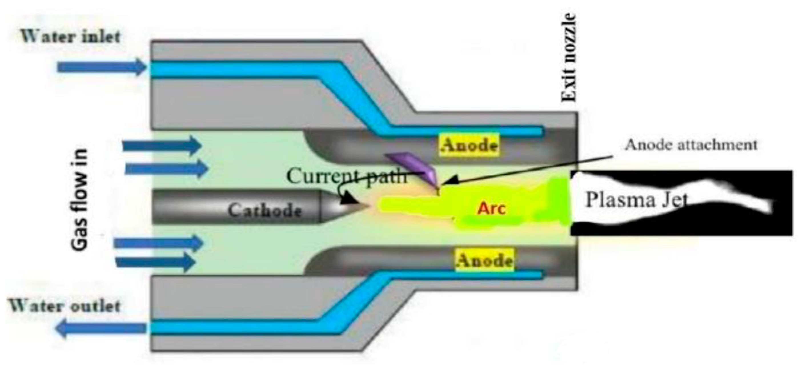
Figure 2.
Schematic diagram of the experimental reactor for plasma gasification treatment of medical plastic waste: 1-waste chopping; 2-waste grinding; 3-windows; 4-plasma torch; 5-water inlet; 6-water outlet; 7-slag; 8-syngas; 9-air and water in; 10-quenching process; 11,12-pyrolosis oil; 13-distillation process; 14-diesel oil.
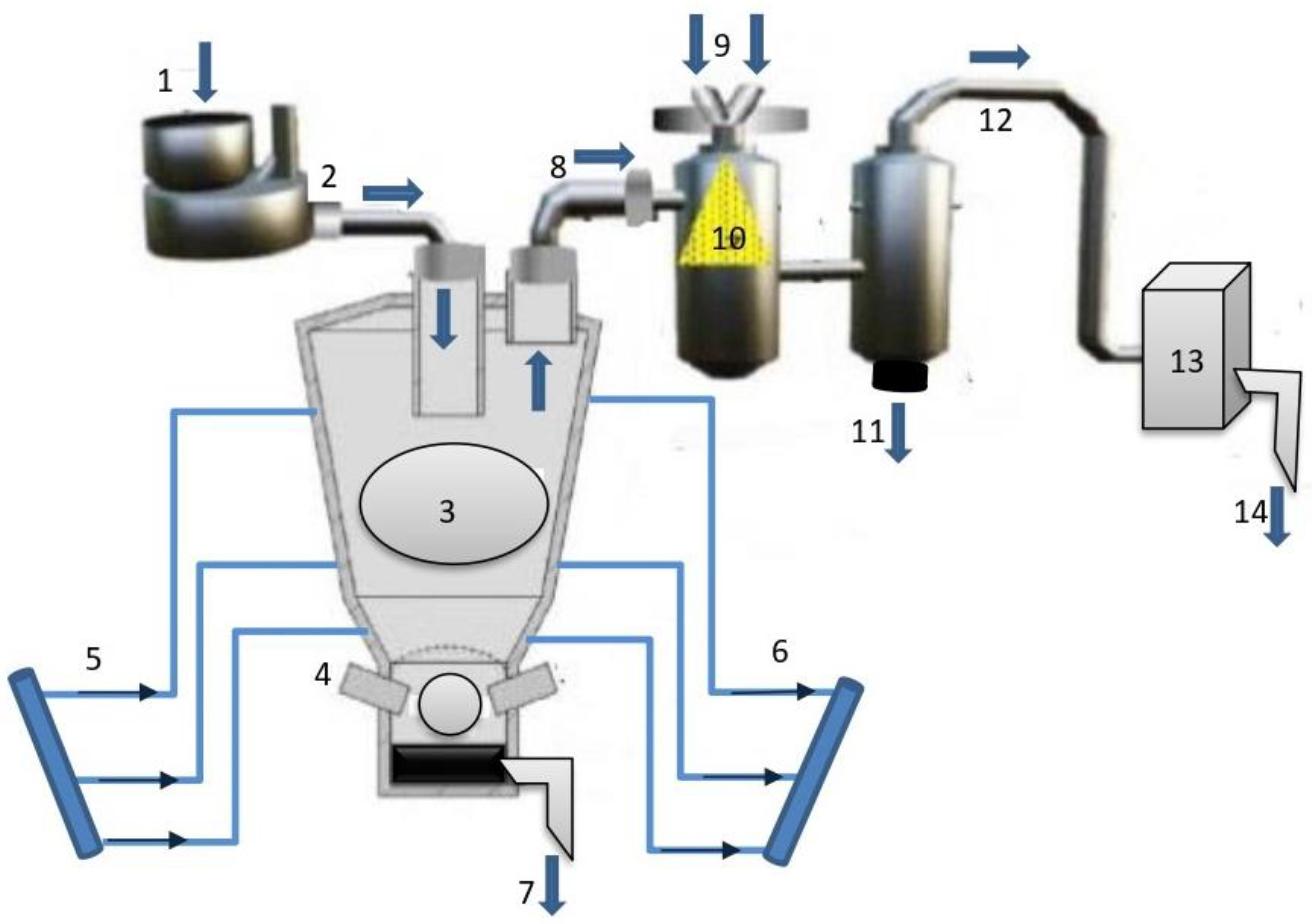
Figure 3.
(a–d) The jet Lengths images with a gas flow rate Ggas from 10 to 40 L/min and with an arc current I = 100 A.
Figure 3.
(a–d) The jet Lengths images with a gas flow rate Ggas from 10 to 40 L/min and with an arc current I = 100 A.

Figure 4.
The electrothermal efficiency of the plasma torch (%) as a function of input power (kW) at different flow rates of air.
Figure 4.
The electrothermal efficiency of the plasma torch (%) as a function of input power (kW) at different flow rates of air.
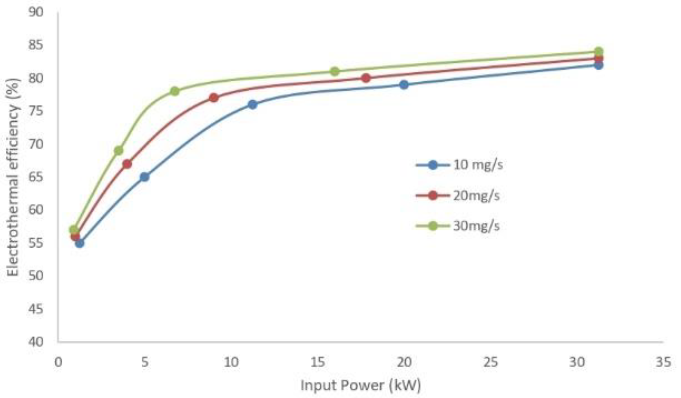
Figure 5.
The electrothermal efficiency of the plasma torch for air flow rate 10 mg/s as a function of .
Figure 5.
The electrothermal efficiency of the plasma torch for air flow rate 10 mg/s as a function of .
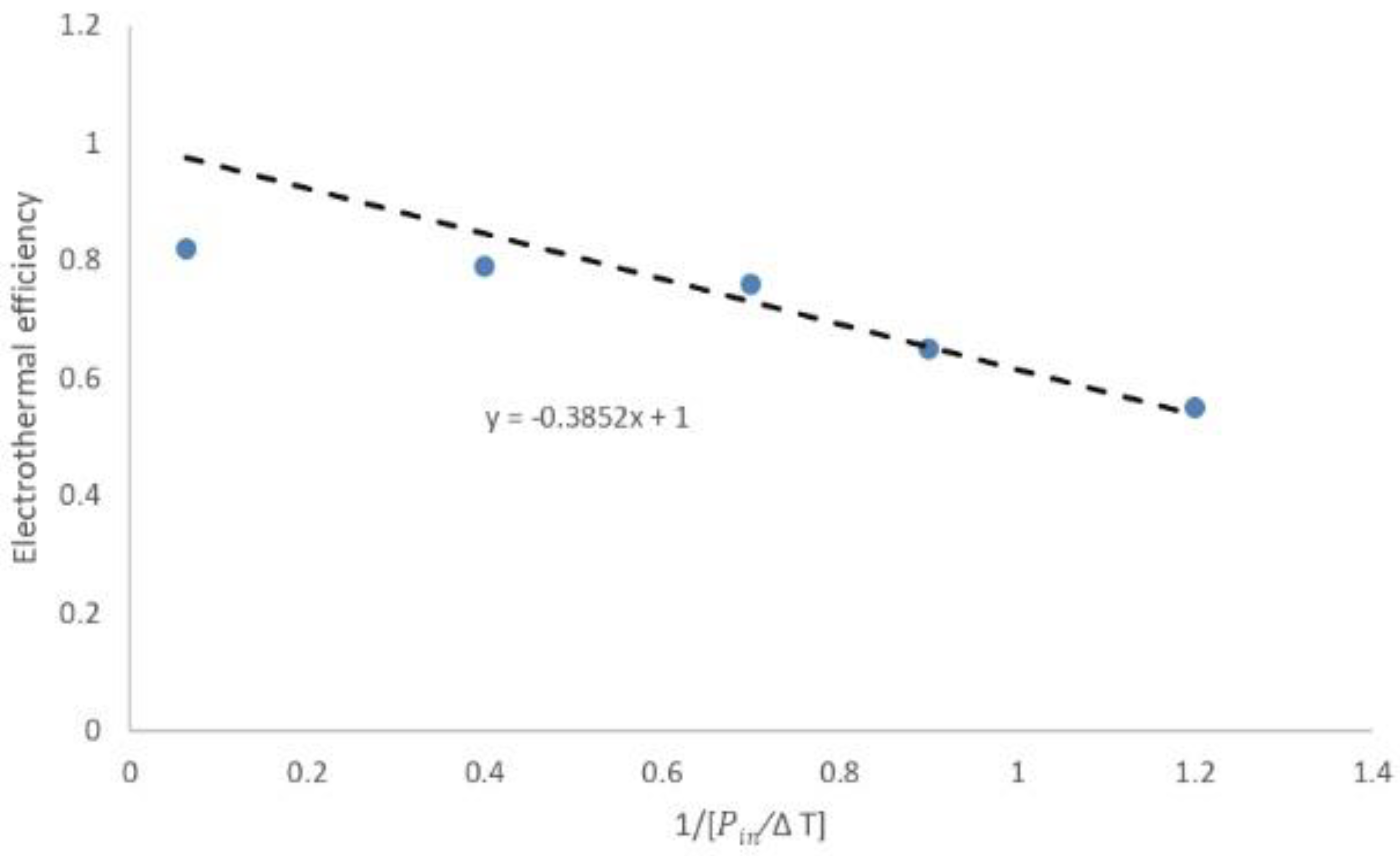
Figure 6.
Pin and Ploss for air flow rate 10 mg/s as a function of (ΔT).
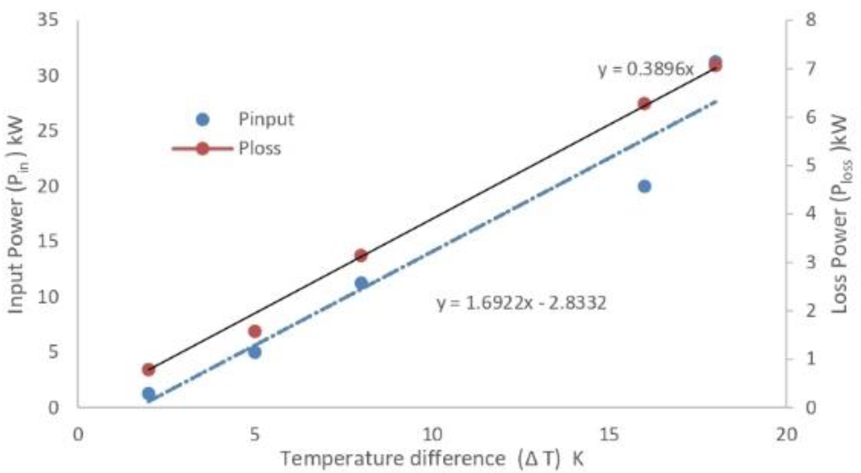
Figure 7.
Plasma flux for air flow rate 10 mg/s as a function of input power.

Figure 8.
Conversion distillation process from pyrolysis oil product to (a) crude oil, brownish-black and viscous, to (b) different types of fuel: (i) gasoline fuel, (ii) kerosene fuel, and (iii) diesel oil.
Figure 8.
Conversion distillation process from pyrolysis oil product to (a) crude oil, brownish-black and viscous, to (b) different types of fuel: (i) gasoline fuel, (ii) kerosene fuel, and (iii) diesel oil.

Table 1.
Air plasma torch parameters.
| Parameter | Amount |
|---|---|
| Power | Direct Current |
| The working active gas | Air |
| Vmax | 500 V |
| Imax | 250 A |
| Pmax. out | 125 kW |
| Tplasma jet | 500–1000 °C |
| Air flow rate | 30 mg/s |
| Cooling system | Inlet and outlet water |
Table 2.
The amount and profits of pyrolysis oil in MAKKAH annually within 1440.
| Parameter | Amount |
|---|---|
| Capacity of plasma reactor | 72 × 103 t |
| No. of beds in hospitals | 10,500 |
| The average weight of Md.W. per bed | 270 t |
| The average weight of Md.W in hospitals | 2835 × 103 t |
| Amount of pyrolysis oil extracted | 2268 × 103 t |
| Amount of diesel oil extracted | 1928 × 103 t |
| Number of gallons of pyrolysis oil | 54,500 × 103 gallon |
| Number of liters of pyrolysis oil | 205 million liters |
| Energy produced from pyrolysis oil | 90 × 109 M J |
| Energy produced from diesel oil | 76 × 109 M J |
| The amount of sale of electricity | 21 × 106 MW·h |
Table 3.
The amount and profits of diesel oil extracted from pyrolysis oil in MAKKAH annually within 1440.
Table 3.
The amount and profits of diesel oil extracted from pyrolysis oil in MAKKAH annually within 1440.
| Parameter | Amount |
|---|---|
| The unit cost of electricity sale | 12 USD/MW·h for home (2022) 17 USD/MW·h for factories (2022) |
| Sale profit of electricity | USD 255 million for home (2022) USD 361 million for factories (2022) |
| Price of each liter of pyrolysis oil | USD 0.042 |
| Sale profit of pyrolysis oil liters | USD 8.61 million (2022) |
Publisher’s Note: MDPI stays neutral with regard to jurisdictional claims in published maps and institutional affiliations. |
© 2022 by the author. Licensee MDPI, Basel, Switzerland. This article is an open access article distributed under the terms and conditions of the Creative Commons Attribution (CC BY) license (https://creativecommons.org/licenses/by/4.0/).
Share and Cite
MDPI and ACS Style
Galaly, A.R. Sustainable Development Solutions for the Medical Waste Problem Using Thermal Plasmas. Sustainability 2022, 14, 11045. https://doi.org/10.3390/su141711045
AMA Style
Galaly AR. Sustainable Development Solutions for the Medical Waste Problem Using Thermal Plasmas. Sustainability. 2022; 14(17):11045. https://doi.org/10.3390/su141711045
Chicago/Turabian StyleGalaly, Ahmed Rida. 2022. "Sustainable Development Solutions for the Medical Waste Problem Using Thermal Plasmas" Sustainability 14, no. 17: 11045. https://doi.org/10.3390/su141711045
Note that from the first issue of 2016, this journal uses article numbers instead of page numbers. See further details here.