Abstract
The stress of rock strata changes under mining action, and the arch structure will be formed around the mining area. The stability study of the arch structure has crucial scientific value for solving the problems of stope pressure and surface subsidence. In this paper, the development process of rock strata arch structure is studied by theoretical analysis and particle flow numerical simulation, and the stability of the arch structure is analyzed. At the same time, based on the rock strata breaking theory, the calculation formulas of the development height and the critical width of the instability of the arch structure are obtained, and the correctness of the formula is verified by numerical simulation. The results show that during the mining stage of the working face, the rock strata arch structure has experienced the process of arching-arch breaking, and the instability of the arch structure is the root cause of increasing surface subsidence damage. The arch structure development height h is the sum of rock strata breaking height Hi and unbroken rock strata arch development height Hig. The theoretical calculation shows that when the width:depth ratio of the working face is 1.60, the height of the arch structure exceeds the bedrock top, which is consistent with the numerical simulation results and verifies the correctness of the formula. By defining the instability coefficient C of rock strata arch structure, a method to judge the stability of the arch structure is provided. The theoretical calculation shows that the critical width L0 of the arch structure instability is 134 m, which is not much different from the numerical simulation results of 136 m, and the correctness of the formula is proved. The research results have particular reference value for preventing ground disasters caused by underground coal mining and controlling ground subsidence and provide a reference for the application of the particle flow method in studying rock strata movement.
1. Introduction
In underground coal seam mining, the stress state of rock strata around the mining area changes, and the overlying strata show bending subsidence, breaking and other phenomena, which are transmitted to the surface and cause subsidence damage [1]. This stage involves the laws of rock strata movement and its control. Many scholars have conducted much research from the perspectives of mining pressure behavior laws, rock strata control [2,3,4,5] and surface subsidence [6,7,8,9]. For example, Bodrac [2] and Holla [3] studied the stope pressure characteristics of the shallow coal seam. It is considered that shallow coal seam mining usually has intense roof activity and rapid pressure, the roof caving height is larger than that of conventional coal seam mining, and the surface subsidence speed is faster. Xu et al. [4] studied the structure form and movement law of the overlaying strata under the condition of large mining height and the influence law of the overlaying strata pressure behavior in the working face. They obtained the difference of mining pressure behavior law in working faces under different rock strata structure forms. Xu et al. [6] took the coal mine of Bulianta Coal Mine as an example, studied the movement law of rock strata and the development characteristics of surface cracks by using the methods of field observation and laboratory test, and believed that the formation cracks were caused by the formation deformation, and the formation cracks, in turn, promoted the formation deformation. In particular, based on existing theories and based on a large number of measured results, many scholars put forward the theory of “pressure arch”, “pre-fracture”, “cantilever beam”, “masonry beam”, “transfer rock beam” and “key layer” [10]. These results fill the gap in movement characteristics of rock strata structure and reasonably explain the stope pressure phenomenon under different geological and mining conditions.
Many studies have shown that the destruction range of rock strata after coal mining is arched, and the arched structure formed by the combination of rock strata blocks in goaf is called arch structure [1,11,12,13,14]. For example, based on the mechanical effect of coal seam excavation and the law of overlying strata movement, Feng et al. [11]. revealed the phenomenon of pressure arch and structural arch in the process of coal mining. Based on the elastic plate theory, Huo et al. [12] established an “arch shell” balanced large structure mechanical model and the mathematical model in large space stope. Through physical simulation model tests, Huang et al. [13] revealed the formation and development of fractures in the sandy soil layer and on the ground surface and found the temporary structure of “arch beam” and the periodic “arch rock” pillar structure. By analyzing the characteristics of overlying strata structure and failure in shallow and flat seams mining, Yang et al. [14] established the structural model of overlying strata pressure arch based on the theory of pressure arch and key stratum. Relevant studies have defined corresponding arch structure models based on different theories. The arch structure is an external form of pressure arch, which can be directly observed under certain conditions, and is the main structure that bears the upper coating load. Its stability determines the composite rock pressure phenomena such as periodic weighting and strata behavior of the working face. In recent years, many scholars have studied the characteristics of stress arching [15,16,17,18], the evolution law of stress arch [19,20,21,22] and the influencing factors of stress arch morphology [23,24,25,26], and have achieved rich results. For example, Angus et al. [15] studied the stress arch effect by coupling simulation. The stress arch effect and the ability to bear overload on both sides of the surrounding rock limit the overall change of effective stress. Dancygier et al. [19] considered the characteristics of arched roof structure and lateral pressure coefficient, established the response analysis model of the dynamic arched structure above the coal seam during excavation under surface static load and verified the model by case analysis. Kong et al. [23] studied the formation characteristics of stress arch in surrounding rock of underground excavation by FEM numerical simulation method, defined the internal and external boundary lines and centroid lines of stress arch, and studied the influence of different factors on the shape of stress arch. The results show that the buried depth and stress state have a greater influence on the stability of the stress arch than the geological strength index and the geometric characteristics of the chamber. The above research results combined with field practice, using different means to study the shape and characteristics of the rock strata arch structure and made some progress. However, the relevant literature is still insufficient to define the stability of the arch structure and the mining conditions of critical instability of the arch structure.
In summary, this paper takes the 22,021 working face in a mining area as the background condition and uses the method of combining theoretical analysis and particle flow numerical simulation to describe the development process of arch structure in the advancing stage of working face, establish the theoretical formula of geological mining conditions and the development height of the arch structure, and explore how to effectively control the mining-induced surface movement and deformation.
2. Method
Coal mining will inevitably form an arch structure inside the rock strata, and its shape and characteristics are closely related to surface subsidence. In this section, the evolution process of the arch structure is studied by theoretical analysis and numerical simulation.
2.1. Overview of Study Area
The study area is located in northern Yulin City, Shaanxi Province, China. The terrain is generally high in the west and low in the east. The highest altitude is 1198.90 m, the lowest altitude is 1151.2 m, and the general altitude is 1152–1198 m. The mining area is located at the edge of the desert, with scarce vegetation and relatively flat terrain, which is a typical plain landform.
The climate in this area is a temperate continental monsoon with clear four seasons and less precipitation. The main coal seam in the mine field is a 2 # coal seam, generally thick 8–10 m. The bedrock is mainly siltstone and mudstone, and the bedrock covers quaternary loess with a thickness of 0–20 m, and the rock strata structure is simple. Figure 1 shows the geographical location of the mining area.

Figure 1.
Geographical location of mine field [27].
The coal seam of the 22,021 working face in the mining area is a #2 coal seam, which is a near horizontal shallow seam. The mining size of the working face is 272 m × 120 m, the maximum mining depth is 90 m, and the average coal thickness is 8 m. The working face adopts fully mechanized top coal caving, longwall backward mining method, and all caving methods to manage the roof; the mining progress is about 2 m/d. Figure 2 is a simplified distribution map of rock strata on the working surface.
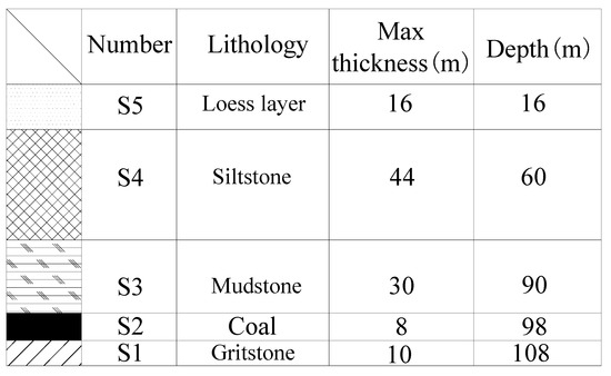
Figure 2.
Simplified distribution of rock strata.
2.2. Rock Strata Breaking Theory and Arch Structure Height Calculation Method
In order to qualitatively analyze the development process of the arch structure, based on the rock strata breaking theory, the height of the arch structure is calculated theoretically from the perspective of a two-dimensional plane.
2.2.1. Rock Strata Breaking Theory
In the process of coal seam mining, the rock strata span will continue to increase. When it reaches the limit, the bedrock will be damaged by tensile shear and broken. When the mined-out area is small, the rock strata show strong motion characteristics of the cantilever beam structure supported at both ends, and the middle part of the rock strata is subjected to elastic bending and subsidence under the upper coating load, as shown in Figure 3a.
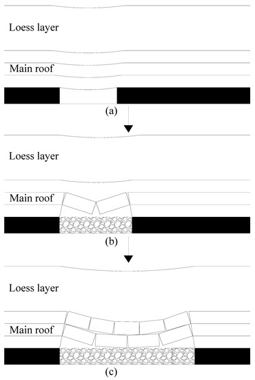
Figure 3.
Rock strata movement process. (a) The cantilever beam structure, (b) The masonry beam structure, (c) The transfer rock beam structure.
With the further expansion of the mining scope, when the span of the basic roof is greater than its limit span, the basic roof will be broken for the first time, and the cantilever beam formed before will become the hinged rock mass at both ends. When the rock mass rotation deformation reaches a certain degree, the hinged force cannot balance the weight of the rock block itself, and the rock block will fall, forming a masonry beam structure with certain support, as shown in Figure 3b.
As the working face continues to advance, under the action of masonry beam structure, the hinged rock block in the advancing direction of the working face continues to transfer the load of the rock strata, and the periodic fracture occurs, forming a certain periodic transfer rock beam structure, as shown in Figure 3c. In the bottom-up caving of the basic roof, the rock strata above the roof will also break due to their limited span and finally reach a balance at a certain position of the rock strata, forming an arch failure area. The area will gradually increase with the advance of the working face, and the surface will bend and sink.
2.2.2. Calculation Method of Arch Structure Height
After the underground coal seam mining, the arch structure will be formed inside the rock strata, which plays a macro supporting role in the whole rock strata, so as to control the surface subsidence and reduce the surface damage. However, for specific geological and mining conditions, with the increase in the working face size, the fracture area and arch development height of rock strata are also increasing, and the roof strata repeat the change process of “arching-arch breaking”, as shown in Figure 4. When the size of the working face reaches a certain critical value, the height of the bedrock will be less than the critical arch height. The macroscopic bearing arch structure in rock strata disappears, and the surface movement, deformation and destruction increase rapidly, which is not conducive to protecting the surface human settlement environment and ecological environment. Therefore, by constructing the theoretical calculation formula of geological mining conditions and arch height, this paper studies the relationship between rock strata height and arch height, defines the instability coefficient of mining-induced rock strata arch structure and realizes the identification of arch structure stability.
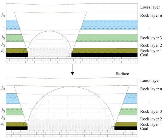
Figure 4.
Development process of arch structure.
The failure height of rock strata is closely related to lithology R, mining height M and working face size L, and arch height h = F (L, M, R). In general, the development of working face advancing and arch structure is a three-dimensional failure process. The working face strike is taken as the control edge of the rock fracture height and simplified to a two-dimensional plane. The calculation height of the arch is the final development height after the mining of the working face, as shown in Figure 5.

Figure 5.
Calculation schematic diagram of overlaying rock arch height.
On the strike section, assuming the mining width of the working face is L, after the mining of the working face is completed, the fracture height develops to the rock layer i, and the fracture height of the rock strata is denoted as Hi.
- (1)
- According to the fracture space form of the positive trapezoidal mining rock strata, the hanging length of the rock layer i is calculated:where ψ is the breaking angle of the rock strata.li = L − 2Hicotψ
Based on the theory of fixed support beam, the fracture distance of rock layer i is calculated:
where RiT is the ultimate tensile strength of the rock layer i; hi is the thickness of rock layer i; qi is the uniformly distributed load on the rock layer i. (This can also be replaced by the criterion of rock strata shear strength, but generally, the ultimate span formed by bending is smaller than that formed by shear stress, so the tensile strength criterion is selected here as the criterion [10]).
The fracture of the rock layer i means that the hanging length of the rock layer has reached its limit fracture distance lik. If li = lik, then the fracture height of the rock strata:
By combining Formula (3) with Hi = Σhj (j = 1, …, i), Hi and i can be solved.
- (2)
- Calculation of development height of unbroken rock strata arch.
Upper arch height Hig of broken rock layer i:
where f is Pu’s coefficient reflecting the lithology of rock strata. When the rock strata are hard, f > 8, when the rock strata are hard, 3 ≤ f < 8, and when the rock strata are weak, f < 3; a′ is the offset of the arch foot, a′ = 0.05 M (H0 − Hi).
- (3)
- Calculation of rock strata arch development height.
The development height of rock strata arch h is the sum of the breaking height of rock strata and the development height of the unbroken rock strata arch.
2.3. Numerical Simulation of Particle Flow Code
According to the above analysis of the rock strata breaking theory, the calculation formula of the arch structure height is obtained. However, because of its many parameters, it is necessary to verify it by numerical simulation.
2.3.1. Principle of Particle Flow Code
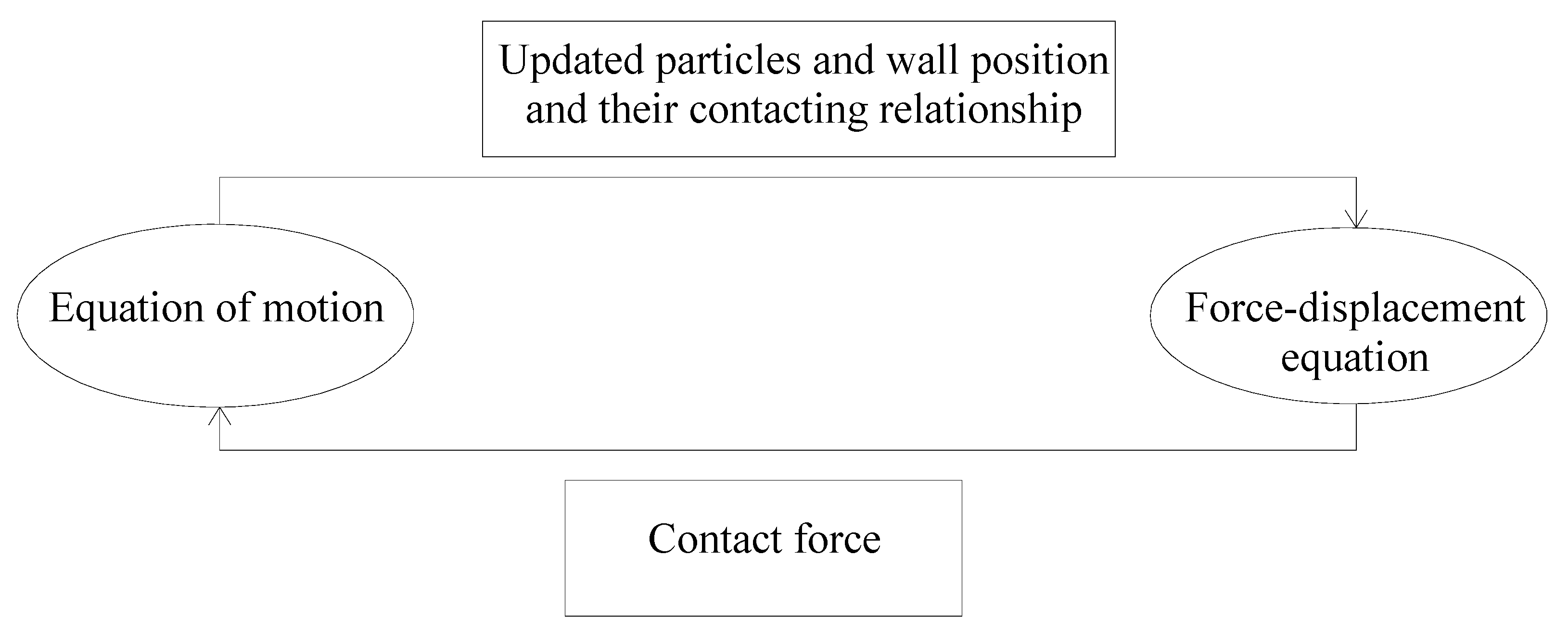
Particle flow code (PFC) is a discrete element program. At first, this method was used to study the characteristics of granular media. With the continuous development of computer technology, the particle flow method has become an effective means to solve geotechnical engineering problems [28]. The numerical model established by PFC is composed of multiple particles. Under stress, the relative position between particles changes, so this method can simulate and solve the large deformation problem. Figure 6 shows the calculation cycle process. This paper uses PFC2D5.0 software developed by the Itasca company [28].
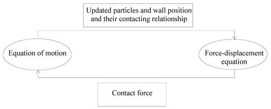
Figure 6.
Calculation cycle process of particle flow code (PFC).
2.3.2. Model Establishment and Parameter Calibration
- (1)
- Model establishment
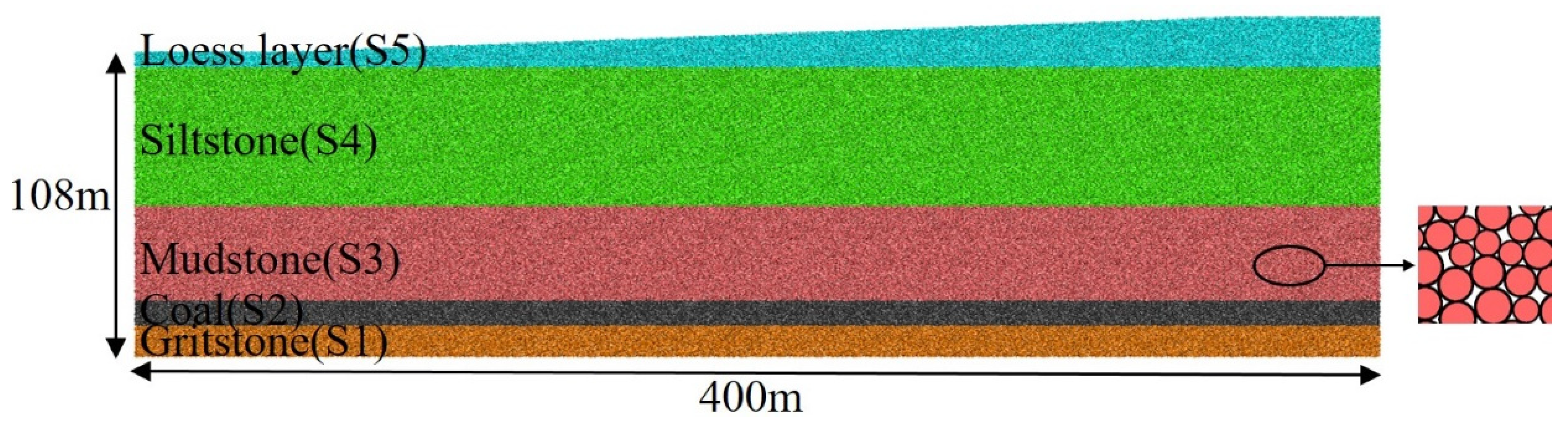
In order to speed up the calculation process, the surface morphology is simplified according to the actual situation, and the two-dimensional particle flow model is established. The maximum size of the model is 400 × 108 m2, as shown in Figure 7. According to the drilling data, the model sets five representative rock strata, generating 174,366 particles, and simulates mining by deleting the particles corresponding to the coal seam.
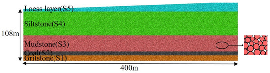
Figure 7.
Particle flow field model.
In the calculation process of the model, the horizontal lateral displacement of the left and right boundaries of the model is constrained, and the fixed support condition is applied at the bottom. The upper boundary is free, and the gravity is loaded on the model (the gravity acceleration is 9.81 m/s2) to simulate the natural accumulation of strata. The open-off cut is 50 m from the left boundary of the model, and 8 m is used to simulate the mining along the strike of the coal seam. After the coal seam is excavated, the force is balanced until the average ratio of the unbalanced force is less than or equal to 1 × 10⁻⁵.
- (2)
- Parameter calibration
Some scholars [29,30] used the parallel bond model to define the particle contact constitutive model to study the rock fracture problem. However, it is found that the parallel bond model has the defect of a small compressive-tensile strength ratio, which is inconsistent with rock materials and cannot simulate the mechanical properties of rock well. The flat joint model overcomes this defect [31,32]. Therefore, the numerical calculation model in this paper is defined by the flat joint model. The calibration process of microscopic parameters of the model is as follows: (1) the uniaxial compression experiment of numerical simulation is carried out by using fish language programming, and the stress–strain curve is obtained, which is compared with the measured stress–strain curve in the laboratory; (2) continuously adjusting the microscopic parameters of the model and repeating the experimental process; (3) when the shapes of the two curves are similar, the effective modulus of flat joints and the stiffness ratio of flat joints at this time are taken as the microscopic mechanical parameters corresponding to different strata. Table 1 shows the microscopic parameters of rock mass calibration in different strata. In the process of numerical simulation, this paper considers the influence of the interface between rock strata on the results. The interface between rock strata is treated as the contact surface, and the thickness is the minimum radius of particles. The mechanical parameters are selected by reference [33,34], which is roughly 1/10 of the mechanical parameters of the surrounding rock strata.

Table 1.
Microscopic mechanical parameters of rock formation.
3. Results
In this section, according to the numerical simulation results, the dynamic evolution process of the arch structure is obtained, and the theoretical calculation formula of the arch structure height is verified. The critical mining width of the arch structure instability is obtained by defining the instability coefficient.
3.1. Analysis of Evolution Law of Rock Arch Structure
After coal seam mining, a relatively stable arch structure will be formed in the rock strata, and it will continue to expand outward with the increase of working face advancing distance, reflecting the movement state of the rock strata, as shown in Figure 8.
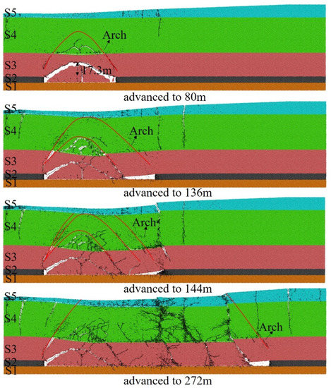
Figure 8.
Evolution of the “arch structure” of overlying strata.
In the early stage of working face mining (80 m), the first collapse of the direct roof occurs, and the height of the collapse is 17.3 m. The development ends in the rock layer S4, with a slight separation phenomenon. At this time, an arch structure with a parabolic shape is formed above the goaf. The front and rear arch feet of the arch are located at the rear of the open-cut and the outer boundary of the coal pillar in front of the working face. The structure bears the weight of the overlying strata in the goaf and makes the surrounding of the goaf re-balance, and there are obvious tension cracks on the surface.
With the continuous expansion of the mined-out area, the span and height of the arch structure further increase. When the working face advances to 136 m, the arch top develops to the interface between the bedrock and loose layer. At this time, the surface appears obvious bending subsidence, and the cracks formed before the surface are further developed, and new cracks are formed in front of the working face.
When the working face advances to 144 m, the arch top exceeds the bedrock surface, and the arch structure stops developing because it exceeds its development limit. At this time, the arch structure cannot bear the load of the overlying strata, resulting in instability. The rock strata above the goaf have collapsed in a large area, and the collapsed rock block continues to fill the goaf. Many cracks appear in the overlying strata and connect with the surface loess to form a penetrating crack. The surface has step subsidence and severe damage.
As the working face continues to advance, the arch height is no longer increased, the span continues to increase, and the degree of surface subsidence damage gradually increases. According to the above analysis, the arch structure has experienced the process of arching-arch breaking. When the arch top development exceeds the bedrock surface, the arch will be unstable, and the surface begins to appear with large subsidence damage. Therefore, determining the critical mining size of the working face can effectively control the influence of coal mining on the surface.
3.2. Analysis of Arch Structure Height Variation
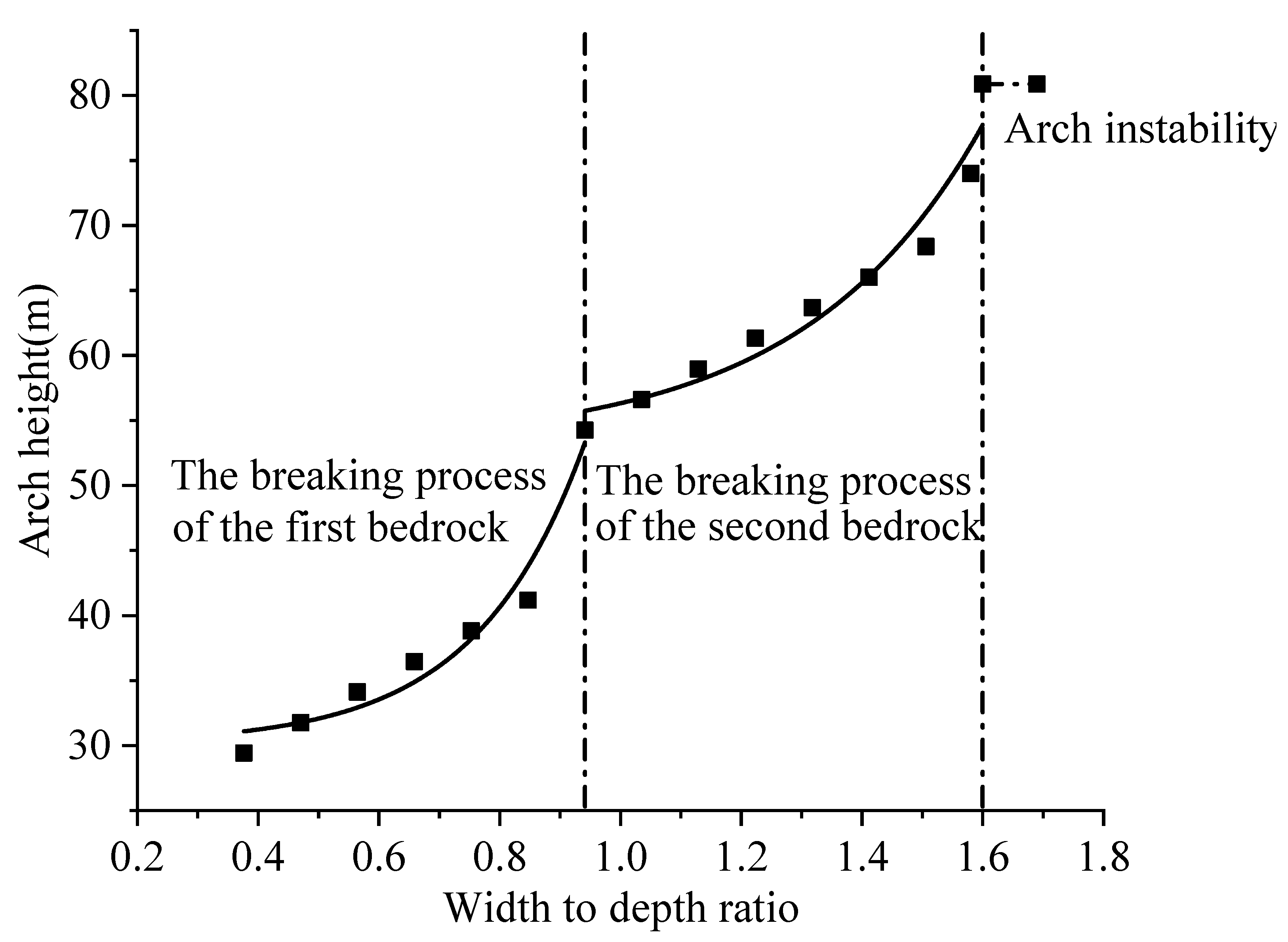
According to the results of numerical simulation, the breaking angle of rock strata is determined to be 55.3°, which is substituted into Formulas (1)–(7) in Section 2.2.2 to calculate the arch height variation curve under different width:depth ratios (the ratio of working face advancing length to mining depth), as shown in Figure 9.
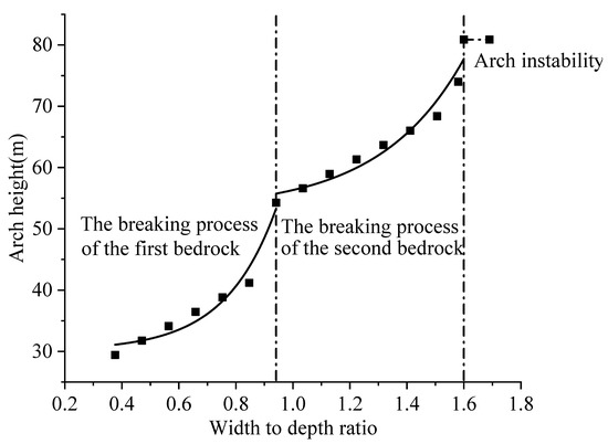
Figure 9.
Relationship between arch height and working face advancing distance.
It can be seen from Figure 9 that in the early stage of working face mining, with the continuous advancement of the working face, the height of the arch structure gradually increases, and the first mutation point appears when the width:depth ratio is 0.85. The arch height is 41.2 m at this time. Then, the arch structure continued to develop, and the second mutation point appeared when the width:depth ratio is 1.51 and the arch height is 68.4 m. When the width:depth ratio is 1.60, the arch height develops to 80.9 m. Since the arch height exceeds the bedrock roof, the arch structure stops developing and becomes unstable. At this time, a large area of ground subsidence begins to occur. As the working face continues to advance, the height of the arch structure is no longer changed, the span continues to increase, and the degree of surface damage gradually increases. The two abrupt change points in the arch height variation curve represent the fracture process of the first rock layer and the second rock layer, respectively.
According to the curve of arch height, the relationship between arch height (h) and width:depth ratio (w) can be divided into three stages, namely, the development stage of arch height in the first rock layer breaking process, the development stage of arch height in the second rock layer breaking process and the development stage of arch height when the arch structure is unstable. The relationship change curve before arch structure instability approximately satisfies the exponential distribution: (A, B and C are undetermined coefficients, which are related to the mechanical properties of each rock layer).
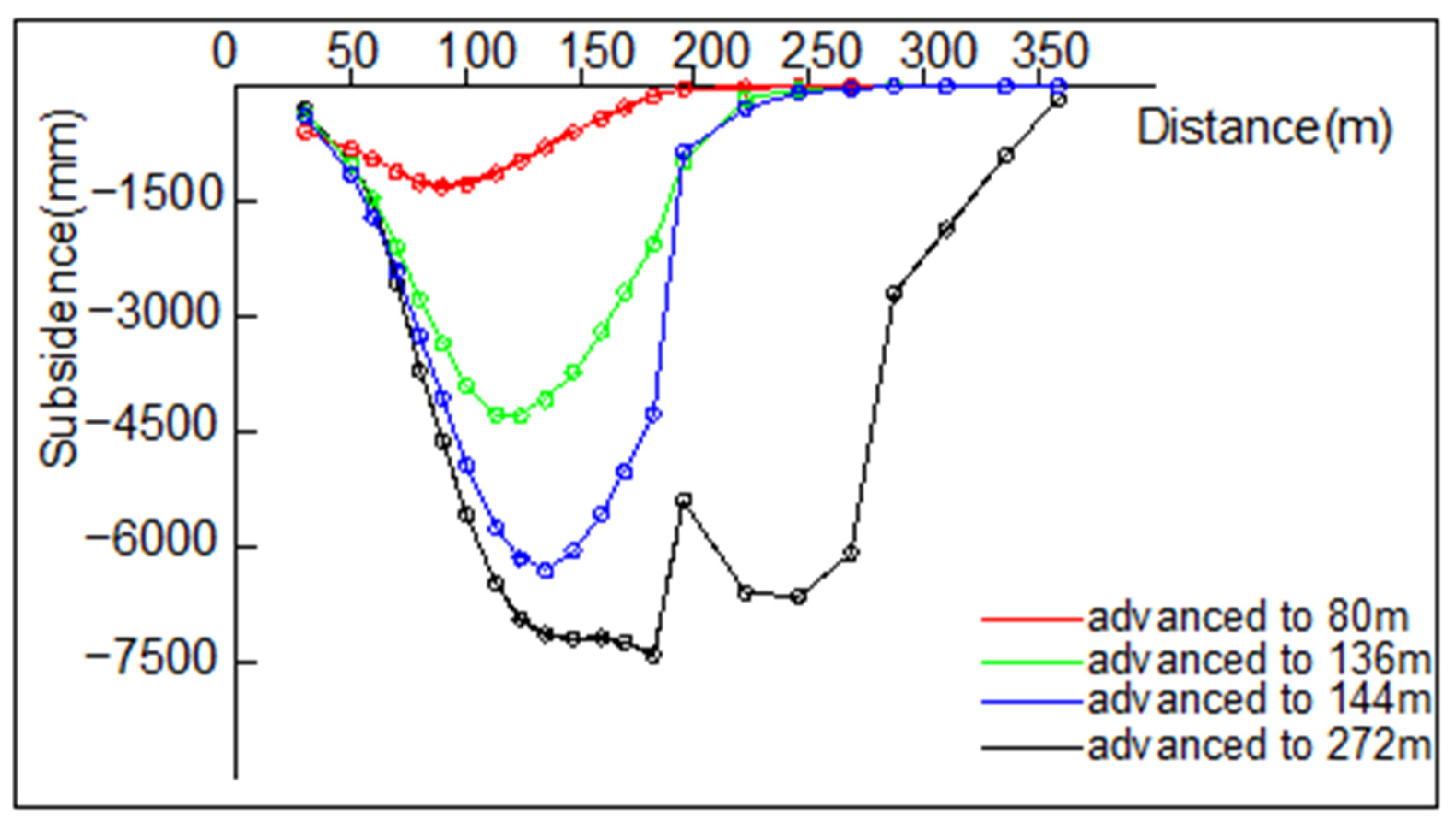
During PFC numerical simulation, the surface subsidence is monitored in real-time and plotted as a curve, as shown in Figure 10. With the expansion of the mined-out area, the surface subsidence and influence range are gradually increasing, and the surface subsidence curve shows a “U” shape. When the working face advances to 80 m, the direct roof breaks first; when the working face advances to 136 m, the arch structure develops to the top of the bedrock, and the second rock layer is completely broken. When the working face advances to 144 m, the arch structure develops more than the top of the bedrock and appears instability. The surface subsidence increased sharply, and the maximum subsidence reached 6325 mm. After the end of the mining face, due to the failure of the surface step, the subsidence value of the corresponding monitoring points above the step rock mass increased sharply, resulting in a mutation in the subsidence curve and the maximum subsidence reached 7250 mm. According to the surface rock movement data, the measured maximum subsidence value is 7000 mm. It can be seen that the numerical simulation results are not much different from the actual results, and the arch height development process obtained by numerical simulation is consistent with the results calculated by the theoretical formula, which demonstrates the correctness of the arch height calculation formula.
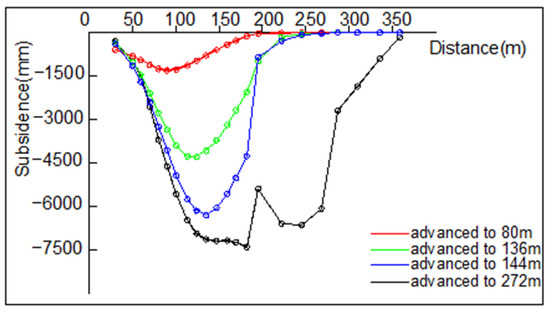
Figure 10.
Numerical simulation of subsidence curve.
3.3. Critical Width Analysis of Arch Structure Instability
Under specific geological and mining conditions, the occurrence conditions of coal seam are determined, and the design mining size of the working face will determine the development height of the arch. When the size of the designed mining face reaches a critical value, the critical arch height will exceed the top of the bedrock. The macro arch bearing structure in the rock strata disappears, and the surface movement and deformation are difficult to be effectively controlled.
Therefore, the ratio of arch height to bedrock thickness is used to define the instability coefficient C of the arch structure. Namely:
where H0 is average mining depth, h is arch height, Hs is loose layer thickness. The instability coefficient is related to the stability of the rock strata arch structure, and the stability of the arch is divided into four categories according to the value range, as shown in the following Table 2.
Table 2.
Discrimination of arch structure stability.
According to the height of the arch structure calculated in Section 3.2, it is substituted into Formula (8) to calculate the instability coefficient under different width:depth ratios, as shown in Table 3. The table shows that when the width:depth ratio is 0.38–1.60, the instability coefficient increases gradually, and the arch structure is stable. When the aspect ratio is 1.58, the arch structure is in a critical instability state. When the width:depth ratio is greater than 1.60, the instability coefficient remains unchanged, the arch structure is unstable, and the surface will appear large subsidence damage. According to the analysis, the instability coefficient can be used to judge the stability of the arch structure and the degree of surface movement and deformation.
Table 3.
Variation of instability coefficient.
For a specific mining area, the geological mining conditions are determined, and the critical mining width of the instability of the arch structure is inversed, which can provide a useful reference for the control of coal mining subsidence.
- (1)
- Discriminant formula for breaking position of rock strata
Based on the rock strata position information of field drilling and indoor mechanical experiment data, combined with Formulas (1) and (2), the relationship between the hanging length of each rock layer and its limit breaking distance is judged layer by layer. When l(i+1)k > li ≥ lik, it is known that the trapezoidal breaking area of the rock strata has reached the rock layer i. Namely:
- (2)
- Calculation equation of critical width
Bring the former Formulas (3), (4) and (7) into Formula (8) to obtain the critical width:
- (3)
- Simultaneous Formulas (9) and (10) are used to inverse the critical width L0 and breaking position i of the instability of the unknown rock strata arch structure.
According to the parameters obtained in the numerical simulation process, Formula (10) is substituted. The critical width L0 of arch structure instability is 134 m, which is not much different from the numerical simulation results of 136 m, which proves the correctness of the formula.
4. Discussion
The development height and the development state of the rock strata arch structure are related to many geological and mining factors. Therefore, based on the rock strata breaking theory, the calculation formula of the rock strata arch structure height is given by theoretical analysis, as shown in Formulas (1)–(7). The results show that the arch height h is determined by factors such as the lithology R, mining height M and working face size L, and the relationship formula is h = F (L, M, R). Huang et al. [13], Yang et al. [14] established the mathematical model of the arch structure from the perspective of structural mechanics, and it is difficult to solve the complex parameters. Compared with their research results, we link the geological mining conditions with the development state of the arch structure, which provides a new idea for solving the dynamic development height of the arch structure.
Angus et al. [15], Dancygier et al. [19], and Kong et al. [23] have carried out much work around the characteristics of stress arching, the evolution law of stress arch and the influencing factors of stress arch morphology and have made great progress. However, the existing results are mostly limited to the study of the development process of the arch structure, and there are few studies on the stability discrimination of the arch structure. Therefore, based on the numerical simulation results, we provide a method to judge the stability of the arch structure by defining the instability coefficient C, and give the calculation formula of the critical mining width of the arch structure instability, as shown in Formula (10), which provides a basis for controlling surface movement and deformation.
Unfortunately, in the research process, the rock strata are regarded as homogeneous, and the development state of the arch structure under special geological structure conditions is not considered. When there are natural cracks or cavities in the rock strata, it will directly affect the stability of the arch structure and easily cause instability and failure. In the next step, the arch structure of the mining area under special geological structure conditions will be studied.
5. Conclusions
- (1)
- The arch structure will be formed in the rock strata after underground coal seam mining, and the calculation formula of arch structure development height h is obtained by theoretical analysis, which is the sum of rock strata breaking height Hi and unbroken rock strata arch development height Hig. According to the numerical simulation parameters, the curve of arch height changing with a width:depth ratio of the working face is obtained. The theoretical calculation shows that when the width:depth ratio of the working face is 1.60, the height of the arch structure exceeds the top of the bedrock, and the surface begins to appear large subsidence damage, which is consistent with the numerical simulation results and verifies the correctness of the formula. The research results are more suitable for mining under a thin loose layer, that is, the ratio of loose layer thickness to mining depth is less than 20%.
- (2)
- In this paper, the ratio of arch height to bedrock thickness is used to define the instability coefficient C of rock strata arch structure, which provides a method to judge the stability of the arch structure. The formula for calculating the critical width of arch structure instability is obtained by theoretical analysis. It is shown that the critical width L0 of the arch structure instability is 134 m, which is not much different from the 136 m obtained by numerical simulation. The correctness of the formula is demonstrated. The results show that the instability of the arch structure is the fundamental reason for increasing the damage degree of surface subsidence.
- (3)
- The biggest advantage of the particle flow method is that it can intuitively see the dynamic evolution process of rock strata movement. The results show that the particle flow method is more suitable for studying the movement and deformation of rock strata, which provides a new idea for related research.
Author Contributions
Conceptualization, Q.L.; methodology, Q.L., Y.Z. (Yanjun Zhang) and Y.Y.; software, Y.Z. (Yanjun Zhang) and Y.Z. (Yongqiang Zhao); validation, Y.Z. (Yuanhao Zhu); formal analysis, Y.Z. (Yanjun Zhang) and Y.Z. (Yongqiang Zhao); investigation, Y.Z. (Yuanhao Zhu) and Y.Y.; resources, Y.Y.; data curation, Y.Z. (Yanjun Zhang); writing—original draft preparation, Q.L. and Y.Z. (Yanjun Zhang); Writing—review & editing, Q.L. and Y.Z. (Yanjun Zhang); visualization, Y.Z. (Yongqiang Zhao); supervision, Y.Y.; project administration, Q.L. and Y.Y.; funding acquisition, Q.L. and Y.Y.; All authors have read and agreed to the published version of the manuscript.
Funding
This research was funded by the State Key Laboratory of Water Resource Protection and Utilization in Coal Mining, grant number (SHGF-16-25, Q.L.), the National Natural Science Foundation of China grant number (51574242, Y.Y.), the Fundamental Research Funds for the Central Universities grant number (2022YJSDC20, 2022YJSDC19, Y.Y.).
Conflicts of Interest
The authors declare that they have no competing interest.
References
- Lou, J.F. Influence mechanism of beam-arch binary structure and strata characteristics on fracture and stress evolution of overlying strata in stope. J. Min. Saf. Eng. 2021, 38, 678–686. [Google Scholar]
- Yan, Y.; Zhang, Y.; Zhu, Y.; Cai, J.; Wang, J. Quantitative Study on the Law of Surface Subsidence Zoning in Steeply Inclined Extra-Thick Coal Seam Mining. Sustainability 2022, 14, 6758. [Google Scholar] [CrossRef]
- Holla, L.; Thompson, K.T. A study of ground movement in three orthogonal directions due to shallow multi-seam longwall mining. Coal J. 1992, 38, 3–13. [Google Scholar]
- Xu, J.L.; Zhu, W.B.; Ju, J.F. Supports crushing types in the longwall mining of shallows seams. J. China Coal Soc. 2014, 39, 1625–1634. [Google Scholar]
- Huang, Q.X.; He, Y.P.; Zhou, H.F. Roof pressure of multiple coal seams mining in Yujialiang mine. J. Xian Univ. Sci. Technol. 2017, 37, 21–25. [Google Scholar]
- Xu, Y.K.; Wu, K.; Li, L.; Zhou, D.W.; Hu, Z.Q. Ground cracks development and characteristics of strata movement under fast excavation: A case study at Bulianta coal mine, China. Bull. Eng. Geol. Environ. 2019, 78, 325–340. [Google Scholar] [CrossRef]
- Guo, W.J.; Sun, X.Z.; Mu, Y.E.; Chen, S.J. Study on Discontinuous Deformation Law and Mechanism of Repeated Mining Surface Ground. Coal Sci. Technol. 2013, 41, 1–4. [Google Scholar]
- Hu, Q.F.; Liu, W.K.; Cui, X.M.; Li, C.Y.; Wang, X.J. Numerical Simulation Experiment of Repeated Mining Overburden and Surface Subsidence Under Coal Pillar Group. Saf. Coal Mines 2019, 50, 43–47. [Google Scholar]
- Wang, J.A.; Shang, X.C.; Liu, H.; Hou, Z.Y. Study on fracture mechanism and catastrophic collapse of strong roof strata above the mined Area. J. China Coal Soc. 2008, 33, 850–855. [Google Scholar]
- Qian, M.G.; Shi, P.W.; Xu, J.L. Mining Pressure and Strata Control; China University of Mining and Technology Press: Xuzhou, China, 2010. [Google Scholar]
- Feng, J.F.; Zhou, Y.; Li, H.G.; Liu, C. Three kinds of basic structures of working face in near horizontal coal seam. J. China Coal Soc. 2016, 41, 2576–2587. [Google Scholar]
- Huo, B.J.; Yu, B.; Zhang, H.W.; Lu, Y.B. Study on formation mechanism of arch shell large structure of overburden in coal mining face with multi layer hard roof. Coal Sci. Technol. 2016, 44, 18–23. [Google Scholar]
- Huang, Q.X.; Zhang, P.; Dong, A.J. Mathematical model of “arch beam” of thick sandy soil layer movement in shallow seam. Rock Soil Mech. 2009, 30, 2722–2726. [Google Scholar]
- Yang, D.M.; Guo, W.B.; Yu, Q.G.; Tan, Y.; Deng, W.N. Structural characteristics and evolution mechanism of overlying strata pressure arch in shallow and flat seams. J. Min. Saf. Eng. 2019, 36, 323–330. [Google Scholar]
- Angus, D.A.; Fisher, Q.J.; Segura, J.M.; Verdon, J.P.; Kendall, J.M.; Dutko, M.; Crook, A.J.L. Reservoir stress path and induced seismic anisotropy: Results from linking coupled fluid-flow/geomechanical simulation with seismic modelling. Pet. Sci. 2016, 13, 669–684. [Google Scholar] [CrossRef]
- Vaziri, H.H.; Jalali, J.S.; Islam, R. An analytical model for stability analysis of rock layers over a circular opening. Int. J. Solids Struct. 2001, 38, 3735–3757. [Google Scholar] [CrossRef]
- Song, H.W.; Du, X.L. Pressure Arch around Rock Cavity and Its Characteristics; China Coal Industry Publishing House: Xuzhou, China, 2012. [Google Scholar]
- Shabanimashcool, M.; Li, C.C. Analytical approaches for studying the stability of laminated roof strata. Int. J. Rock Mech. Min. Sci. 2015, 79, 99–108. [Google Scholar] [CrossRef]
- Dancygier, A.N.; Karinski, Y.S.; Chacha, A. A model to assess the response of an arched roof of a lined tunnel. Tunn. Undergr. Space Technol. 2016, 56, 211–225. [Google Scholar] [CrossRef]
- Yang, K.; Xie, G.X. Modeling and analyzing on the development of mining induced stress shell in deep longwall mining. J. China Coal Soc. 2010, 35, 1066–1071. [Google Scholar]
- Luo, S.H.; Wu, Y.P.; Liu, K.Z.; Xie, P.S.; Lang, D. Study on the shape of the space stress arch shell in steeply dipping coal seam mining. J. China Coal Soc. 2016, 41, 2993–2998. [Google Scholar]
- Xia, B.W.; Zhang, X.; Yu, B.; Jia, J.L. Weakening effects of hydraulic fracture in hard roof under the influence of stress arch. Int. J. Min. Sci. Technol. 2018, 28, 951–958. [Google Scholar] [CrossRef]
- Kong, X.X.; Liu, Q.S.; Zhang, Q.B.; Wu, Y.X.; Zhao, J. A method to estimate the pressure arch formation above underground excavation in rock mass. Tunn. Undergr. Space Technol. 2018, 71, 382–390. [Google Scholar] [CrossRef]
- Xie, G.X.; Wang, L. Lithologic effect on the mechanical characteristics of mining-induced stress shell. J. China Coal Soc. 2013, 38, 44–49. [Google Scholar]
- Xie, G.X.; Wang, L. Effect of longwall length on mechanical characteristics of surrounding rock stress shell in mining face. J. China Coal Soc. 2008, 33, 1336–1340. [Google Scholar]
- Wang, S.R.; Li, N.; Li, C.L.; Chen, C. Distribution characteristics analysis of pressure-arch in horizontal stratified rocks under coal mining conditions. Teh. Vjesn. 2015, 22, 997–1004. [Google Scholar] [CrossRef]
- Zhang, Y.; Yan, Y.; Dai, H.; Zhu, Y.; Wu, T. Stability and force chain characteristics of “inclined step cutting body” in stope. Appl. Sci. 2021, 11, 10276. [Google Scholar] [CrossRef]
- Itasca Consulting Group Incorporated. PFC (Particle Flow Code in 2 and 3 Dimensions); Version 5.0 [User’s Manual]; Itasca Consulting Group Incorporated: Minneapolis, MN, USA, 2016. [Google Scholar]
- Ghazvinian, A.; Azizian, F.; Nejati, H. Failure analysis of transversely isotropic rocks-A numerical study. J. Mines Met. Fuels 2013, 61, 43–53. [Google Scholar]
- Amin, M.; Mohammad, F.M. Numerical analysis of confinement effect on crack. propagation mechanism from a flaw in a pre-cracked rock under compression. J. Mech. 2012, 28, 1389–1397. [Google Scholar]
- Lian, X.; Zhang, Y.; Yuan, H.; Wang, C.; Guo, J.; Liu, J. Law of Movement of Discontinuous Deformation of Strata and Ground with a Thick Loess Layer and Thin Bedrock in Long Wall Mining. Appl. Sci. 2020, 10, 2874. [Google Scholar] [CrossRef]
- Chen, P.Y. Research progress on PFC2D simulation of crack propagation characteristics of cracked rock. J. Eng. Geol. 2018, 124, 253–264. [Google Scholar]
- Xia, L.; Zeng, Y.W.; Zhang, S. Influence of Meso-Mechanical Parameters of Bedding Plane on Strength Characteristics of Layered Rock Mass. J. Yangtze River Sci. Res. Inst. 2016, 33, 68–75. [Google Scholar]
- Chen, J.H.; Liu, P.; Liu, L.; Zeng, B.Q.; Zhao, H.B.; Zhang, C.; Zhang, J.W.; Li, D.Q. Anchorage performance of a modified cable anchor subjected to different joint opening conditions. Constr. Build. Mater. 2022, 336, 1–12. [Google Scholar] [CrossRef]


Publisher’s Note: MDPI stays neutral with regard to jurisdictional claims in published maps and institutional affiliations. |
© 2022 by the authors. Licensee MDPI, Basel, Switzerland. This article is an open access article distributed under the terms and conditions of the Creative Commons Attribution (CC BY) license (https://creativecommons.org/licenses/by/4.0/).