Article

Improving Thermoacoustic Low-Temperature Heat Recovery Systems †

1
School of Energy and Power, Jiangsu University of Science and Technology, No. 2 Mengxi Road, Zhenjiang 212000, China
2
Mechanical Engineering Educational and Scientific Institute, Admiral Makarov National University of Shipbuilding, Heroes of Ukraine Avenue 9, 54025 Mykolayiv, Ukraine
*
Author to whom correspondence should be addressed.
This paper is an extended version of our paper published in 2022 ECRES 2022, Proceedings, 778-784.
Sustainability 2022, 14(19), 12306; https://doi.org/10.3390/su141912306
Submission received: 26 August 2022 / Revised: 20 September 2022 / Accepted: 24 September 2022 / Published: 27 September 2022
(This article belongs to the Special Issue Energy Recovery, Sustainability and Waste Management)

Abstract

:
The existence and development of modern society require significant amounts of available energy. Combustion engines are the main sources of heat. Their operation is accompanied by the formation of large volumes of emissions, which have different temperatures and contain harmful substances ejected into the environment. Therefore, the urgent problem today is the reduction in heat emissions. This might be achieved through a reduction in the amount of these pollutants by improving primary heat engines, converting to new, alternative types of fuel, and at the same time, to carbon-free fuel. However, such measures only reduce the temperature level of waste heat but not its volume. Conventional technologies for the utilization of heat emissions are ineffective for using heat with temperatures below 500 K. Thermoacoustic technologies can be used to convert such low-temperature heat emissions into mechanical work or electricity. This article is focused on analyzing the possibilities of improving the thermoacoustic engines of energy-saving systems through the rational organization of thermoacoustic energy conversion processes. An original mathematical model of energy exchange between the internal elements of thermoacoustic engines is developed. It is shown that the use of recuperative heat exchangers in thermoacoustic engines leads to a decrease in their efficiency by 10–30%. From the research results, new methods of increasing the efficiency of low-temperature engines of energy-saving systems are proposed.

1. Introduction

A characteristic feature of current times is a steady trend toward reducing the emission of so-called green gases. Currently, the greatest attention is paid to the reduction in the emissions of carbon greenhouse gases—CO2, CO, NOx, VOL—which requires the solution of complex technical and technological problems by the manufacturers of heat engines [1,2,3].
For industry, transport, and energetics, this means the need to implement more efficient production technologies and primary heat engines, the transition to new, more ecological types of fuel, including water fuel emulsions [4,5], and low-carbon and carbon-free fuels [6,7]. The practice has shown that such changes, as a rule, lead to a change in the structure of thermal emissions due to an increased share of low-temperature components [8,9].
The operation of any type of heat engine is accompanied by the emission of pollutants of various natures, which are a collection of material flows of different chemical compositions and with different temperatures. The utilization of thermal emissions is possible by the application of low-temperature economizer surfaces and well-known energy-saving systems of heating [10,11,12], cooling [13], cogeneration, and trigeneration. Further improvement in the efficiency of heat engines leads to a decrease in the temperature of heat emissions, particularly the exhaust gases of internal combustion engines (ICEs) (Table 1).
Environmentally safe and economically reasonable energy production is becoming the main paradigm for the existence and development of modern energetics [14]. This approach is typical for industrial and food-treating energetics [15], the transport industry, and maritime shipping [16].
The total volume of the thermal emissions of ship power plants (SPPs) with a temperature potential in the range of 480–530 K reaches (4.3–4.9) × 1015 kJ, 2.5–8.5% of which is disposed of, and therefore, reducing this volume is a significant measure to improve the technical, economic, and environmental characteristics of ship power plants [17].
The problem of the utilization of heat with temperatures below 500 K is acute, which is impossible with the help of traditional energy-saving technologies. In particular, such tasks are relevant for ship power engineering and maritime activities (Table 2).
Such heat recovery systems can be implemented on the basis of various thermodynamic cycles, for example, the Rankine cycle (on water or organic heat carriers) [18,19], the A. Kalina cycle [20], the trilateral cycle (TC), and using turboexpander, ejector, and thermopressor [21,22] technologies to convert high-pressure and exhaust heat potential into mechanical work and refrigeration. The latter can be used for cooling combustion engine cyclic air [23,24] leading to a reduction in fuel consumption and thermal and other harmful emissions as a result. The issue of the utilization of thermal emissions with temperatures below 573 K is a difficult task and requires appropriate technologies.
One of the methods of low-potential heat usage is the application of thermoacoustic technologies. Thermoacoustic heat machines (TAHMs) differ from mechanical structures in the simplicity of their construction, as well as the absence of moving fragments and environmentally destructive working materials [25,26]. The main advantages of thermoacoustic systems are reliability, low cost, and the ability to operate using any type of heat source, including cryogenic ones [27].
The operational principle of thermoacoustic systems is grounded on the thermoacoustic effects resulting from the alternate transformation of heat and acoustic energy. TAHMs can be divided into direct-action heat machines, such as thermoacoustic engines (TAEs), or reverse-action engines and machines, such as thermoacoustic refrigerators (TARs). The first group, TAEs, convert heat into acoustic energy, while the second group of these systems, such as thermoacoustic refrigerators or heat pumps, implement the reverse conversion of acoustic energy into heat with different temperatures [28,29].
There are thermoacoustic engines and refrigerators that implement the Brayton thermodynamic cycle. These TAEs have a simple design but low thermodynamic efficiency [30]. TAHMs operating on the Stirling cycle [30] have greater efficiency, more than twice the efficiency of thermoacoustic engines using the Brayton cycle. The first thermoacoustic Stirling engine provided a power of more than 1 kW [31,32].
Thermoacoustic heat recovery systems were investigated as complex systems of interlinked elements [33]. A general diagram of power plants with thermoacoustic heat recovery systems is shown in Figure 1. This is a universal scheme, which holds true for any TAE for the utilization of low-temperature heat with different temperature levels. Thermoacoustic systems can use any type of external low-temperature thermal resource, including a cryogenic source.
Thermoacoustic refrigerators or special acoustic–electric converters may be used similarly to loaded thermoacoustic engines. The most versatile result is the creation of thermoacoustic cogeneration systems based on TAEs, such as prime heat transformers, acoustic–mechanical converters, and turbogenerators with bidirectional turbines [34,35]. Such generators allow for the efficient conversion of acoustic energy into mechanical work and electric current. Some types facilitate the creation of effective thermoacoustic devices with an aggregate power in the range of 10–1000 kW; this contributes to the widespread implementation of thermoacoustic energy-saving technologies [36].
The creation of low-temperature TAEs for using heat sources with temperatures of 373–473 K is gaining considerable practical interest. The utilization of such heat sources is a significant scientific and technical problem and requires special studies of the peculiarities of thermophysical processes affecting the efficiency of thermoacoustic transformations.
The widespread usage of TAHMs is challenged by their small power density, difficulty in the direct production of mechanical work or electricity, and the lack of practical experience in using them.
Unfortunately, experimental investigations of thermoacoustic low-temperature heat plants have shown a number of problems that reduce their efficiency. An analysis of the results of the existing research allows one to assume that internal recuperative heat exchangers will significantly affect the efficiency of low-temperature thermoacoustic devices. Therefore, the purpose of this work is to study the possible impact of recuperative heat exchangers on the processes of thermoacoustic transformations and the characteristics of low-temperature thermoacoustic devices.

2. Materials and Methods

2.1. General Assumptions and Hypothesis

This investigation was based on the hypothesis that the rational organization of energy exchange processes in the thermoacoustic core (TAC) has a decisive influence on the efficiency and characteristics of thermoacoustic heat engines in general.
The main element of thermoacoustic transformation in thermoacoustic heat machines is the TAC, which consists of recuperative heat exchangers, namely a heater, a cooler, and a porous matrix located between them.
Thermoacoustic devices use recuperative liquid–gas heat exchangers made of finned tubes. Intermediate fluid coolants move inside the pipes. From the outside of the heat exchangers, in the transverse direction, the gaseous working body of the TAE carries out harmonic oscillations. Thus, in TAC heat exchangers, we have a strictly transverse movement of coolants, while the gaseous coolant carries out the oscillating motion (Figure 2).
A multilevel mathematical model of the installation shown in Figure 1 was designed. This model allowed for an investigation of the impact of different factors on the efficiency of a power plant with a thermoacoustic heat recovery circuit. The power plant was formalized by a system of balance equations of the energy and material flows of existing heat emissions [32]. A mathematical model that was built from discrete modules was created with the following assumptions:
  • The TAE works due to the difference in temperature between high- and low-potential energy sources;
  • Low-potential sources may have an ambient temperature or lower temperature (cryogenic);
  • The energy sources are not connected to the TAE through thermodynamic cycles;
  • The energy exchange between the thermoacoustic engine and the energy sources is carried out by means of external systems with intermediate heat carriers;
  • The load of the TAE can be electric generators or thermoacoustic machines of reverse action, namely refrigerators.
The proposed model considered the load regimes of power plant engines, some environmental parameters, the thermophysical qualities of working substances, and external heat carriers. TATGs should ensure the conversion of heat emission energy into electrical energy by carrying out successive energy transformation processes.
A thermoacoustic turbogenerator consists of a bidirectional turbine with a joined electric generator.
The overall power of (Figure 1) may be defined as a sum
N e Σ P P = Ne e n g + Ne T A T G ,
where
N e T A T G = Q i n T A E η C a r n o t η T A E η t u r b η g e n , N e T A T G = Q i n T A E η C k H E X η T A E η t u r b η g e n = ( Q i n T A E Q o u t T A E ) × ( 1 T C T H ) k H E X η T A E η t u r b η g e n
The waste heat module “Source” is considered to be a set of thermophysical parameters of high-potential coolants. These parameters are determined by the type and structure of the primary power plant, its load modes, and other factors. The module called “Sink” characterizes the current parameters of low-potential coolants, and heat runoff can be the environment, or other low-potential heat carriers such as LNG, LNH3, etc.

2.2. Investigation of Energy Exchange Processes in Low-Temperature TAE

The TAE of WHRS is connected to outlying energy sources via intermediate systems through which liquid heat carriers are circulated. According to [26,27], thermoacoustic conversions occur in the TAC, where part of the full of energy flow H ˙ 2 , here heat, Q i n T A E is converted to acoustic energy E ˙ 2 .
The formalization of the TAE is based on the linear theory of thermoacoustic processes [27] in the form of a system expressed in Equation (3).
d p 1 = i ω ρ m d x A 1 f ν U 1 d U 1 = i ω A d x γ p m 1 + γ 1 f k p 1 + f k f ν 1 σ 1 f ν d T m T m d x U 1 ,
Equation (3) produces a linear, one-dimensional mathematical model of thermoacoustic transformations for the matrix element dx. In this case, i.e., for calculating the characteristics of a real thermoacoustic machine, integral relations are considered.
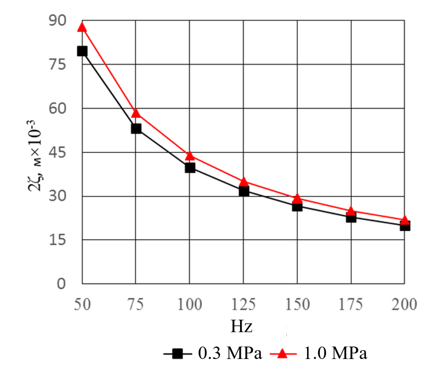
Recuperative heat exchangers (HEXs), one of the important features of low-temperature TAEs, must have a large frontal surface and a small longitudinal size 2 ζ .
ζ 0.05 0.1 P m ω ρ C = 0.05 0.1 P m 2 π f ρ χ R T ,
This parameter, according to the recommendations [37,38], should not exceed the double amplitude of the oscillating motion of the working environment and depends on the frequency and physical properties of the working media (Figure 3).
In this case, this parameter is of crucial importance, as it completely determines the frontal dimensions of the TAC and, accordingly, the overall dimensions of the TAE as a whole.
Grounded on the linear model of thermoacoustic processes, it can be assumed that H ˙ 2 = Q ˙ H . By taking into account the basic principles of finite-time thermodynamics [39,40], E T A D F T T = E T A D M R S , as well as the accepted assumptions, it is possible to establish a direct relationship between the intensity and efficiency of the processes of heat and energy exchange in the TAC and their effects on the performance of the TAE and thermoacoustic system.
TAE recuperative heat exchangers deserve special attention, as they are an essential part of the heat engine—the primary mover. Thermoacoustic core heat exchangers perform the following two functions:
  • They organize the heat flow between external energy sources with different temperature potentials;
  • However, at the same time, these are vital elements of the heat engine, which form a longitudinal temperature gradient in the matrix.
H ˙ 2 E ˙ 2 = 1 2 ρ m T m Re [ s 1 u ˜ 1 ] d A ( A k + A s o l i d k s o l i d ) d T m d x ; Δ E ˙ 2 = Q ˙ H Q ˙ C = k 1 F H E X f 1 ϕ χ T H n ( T C / χ ) n ( 1 + f ) ( 1 + ϕ f χ 1 n ) Q ˙ H = 1 α H + δ W λ W + 1 α g a s H F F + ξ F H E X H 1 F H E X H T H T g Q ˙ L = 1 α C + δ W λ W + 1 α g a s C F F + ξ F L H E X C 1 F H E X C T C T g H ˙ 2 = Q ˙ H
These circumstances indicate the expediency of considering special requirements for heat exchangers with a thermoacoustic core, namely, the supply of the required amount of heat under such conditions with minimal thermodynamic irreversibility.

2.3. Analysis of the Influence of Heat Exchanger Surface Temperature Inhomogeneity on Transformation Processes in TAE

According to the linear model of thermoacoustic processes, the power of a TAE depends on the amount of heat that the heater is able to carry to the working body and the matrix, and the intensity of the processes of thermoacoustic transformations. In TAEs, it is most appropriate to use heat exchangers with flat finned tubes.
The actual issue of the influence of irreversibility in heat exchangers on the efficiency of thermoacoustic devices was fruitfully investigated in [39,40].
Numerous works [41,42,43] are devoted to the study of the heat exchange processes between the surfaces of heat exchangers and the pulsating medium. In these works, it is shown that, in a pulsating gas flow, under TAE conditions, the heat exchange coefficients can reach 500–1500 W/(m2/K), which is significantly higher than the heat exchange coefficients between the tubes and the liquid coolant, i.e., the thermal fluid. On the basis of these studies, it can be asserted that the thermal resistance of TAE heat exchangers depends on the heat exchange inside the recuperator tubes [44,45,46].
However, there are several remarks that can be made by analyzing the system in (5):
  • Firstly, the existing linear theory of thermoacoustic processes is built on the basis of the one-dimensional Rott–Swift model [26,27], so it does not take into account the inhomogeneity of the temperature distribution on the surface of recuperative heat exchangers;
  • Secondly, the model uses the integral values of heat exchange coefficients, which is quite acceptable for ordinary recuperators, but in TAE heat exchangers, heat exchange is carried out under the conditions of the initial sections, namely hydrodynamic and thermal conditions, which must be taken into account.
As shown in [27], in the element of the matrix TAE with length dx, in the presence of a longitudinal temperature gradient d T m / d x , and working body oscillations, additional acoustic energy is produced, which is denoted as follows:
d E ˙ r e g d x = r ν 2 U 1 2 1 2 r k p 1 2 + 1 2 Re g p ˜ 1 U 1 ,
where the viscous component of the acoustic resistance is:
r v = ω ρ m Im [ f v ] A 1 f v 2 ,
and the thermorelaxation component of the acoustic resistance is:
1 r k = γ 1 γ ω A Im [ f k ] p m ,
The first two components in Equation (6) are dissipative and are associated with viscosity and thermorelaxation processes. They do not depend on the longitudinal gradient of temperatures dt/dx.
The third component, 1 2 Re g p ˜ 1 U 1 , characterizes the increase in acoustic energy, while the coefficient of the “amplification” of acoustic energy in the matrix is defined as follows:
g ( x ) = f k f ν 1 σ 1 f ν 1 T m d T m d x ,
It is assumed that the complex system of thermophysical and geometrical parameters in (9) depends only on the type of the matrix and the thermophysical parameters of the working body and does not depend on the longitudinal coordinate.
In this circumstance, the following equation can be expressed:
Φ f k , f ν , σ = f k f ν 1 σ 1 f ν ,
Then, the expression in (12), taking into account (13), can be written as
g ( x ) = Φ f k , f ν , σ × 1 T m ( x ) d T m ( x ) d x = Φ f k , f ν , σ × Θ T m ( x ) ,
The key point of the linear theory of thermoacoustic processes is the assumption that the volumetric velocity, the temperature of the working environment, and the temperature of the matrix are functions of only the longitudinal coordinate x.
In the conditions of using recuperative heat exchangers, statement (6) is incorrect, so expression (9) needs clarification, which will lead to the modification of the existing one-dimensional model of the thermoacoustic system.
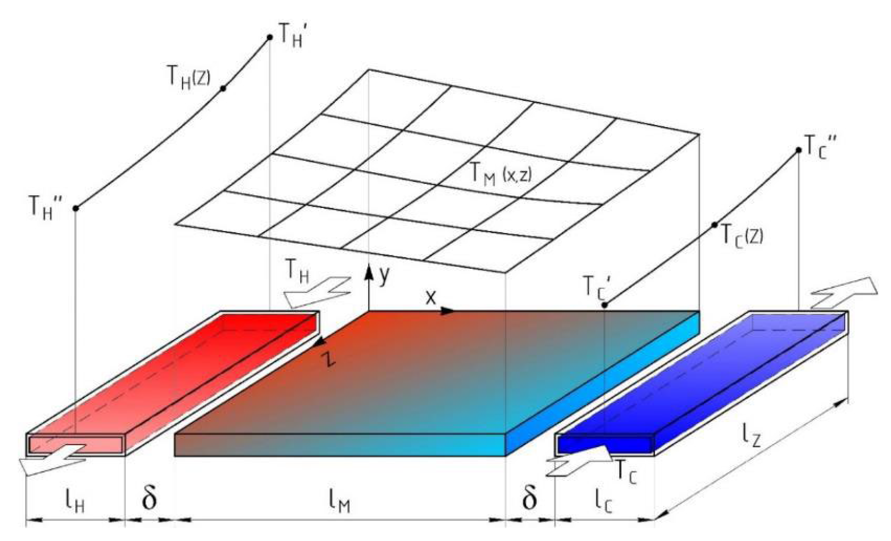
For the investigation of this phenomenon, a mathematical model of processes in the matrix of the TAE was developed. The scheme of this model is shown in Figure 4.
Suppose that the design of the pipe collectors of heat exchangers ensures a uniform distribution of transporting the coolants through the tubes of the heat exchangers. In heat exchangers, the tubular-rib surface of heat exchange is used.
Let us assume that part of the thermal energy supplied by the heater is converted into mechanical energy in the form of acoustic oscillations, and the rest of the heat is released into the environment with the help of a cooler. Within the heat exchange unit TAE, there are no losses of thermal energy outside.
One considers the element of the TAC to consist of two separate tubes—a heater and a cooler—each with the length of lZ and a matrix, the longitudinal size of which is lM.
Given the complexity of the processes at the TAC, certain assumptions were made:
  • Provided that the TAE operates in the steady state, the distribution of the temperatures in the elements of the heat exchange unit is stabilized and unchanged;
  • Regenerative heat exchangers have a tubular-rib structure, and the liquid in the tubes passes through once;
  • The intermediate transport coolants, namely thermal oils and water, move in the tubes of the recuperative heat exchangers;
  • The distribution of the temperature field in the TAE matrix is determined by the distribution of temperatures over the outer surfaces of the recuperative heat exchangers;
  • Taking into account the high thermal conductivity of the material of the heat exchanger tubes, we believe that the surface temperatures of the tubes in each lumbar section are the same and change only along the length of the tube and are equal to the temperatures of the transport coolers;
  • Working fluid—gas that makes oscillation movement across the liquid coolant flow;
  • The thermal resistance of each of the heat exchangers, heaters, and coolers determines the heat transfer coefficient on the inner surface of the tubes as a value much lower than the heat exchange coefficient from the outside.
Equations (6) and (9) were modified into 2D equations:
d E ˙ 2 d x = r ν 2 U 1 2 1 2 r k p 1 2 + 1 2 Re p ˜ 1 U 1 g ( x , z ) ,
g ( x , z ) = f k f ν 1 σ 1 f ν 1 T ¯ m ( x , z ) d T m ( x , z ) d x = f k f ν 1 σ 1 f ν Θ T m ( x , z ) ,
to consider the peculiarities of the energy exchange between the internal recuperative heat exchangers of a thermoacoustic machine with a matrix of a TAE and a working fluid.
Under these assumptions, the complex in Equation (12) also becomes a function of two coordinates x and z, namely,
Θ T m ( x , z ) = 1 T M ( x , z ) d T m ( x , z ) d x
The temperature in the volume of the matrix is determined in the form of a function,
T m ( x , z ) = Ψ ( z ) × ϒ ( x ) ,
at the same time,
μ 1 = α 1 ( z ) × Π 1 G 1 c p 1 , μ 2 = α 2 ( z ) × Π 2 G 2 c p 2
where α 1 ( z ) and α 2 ( z ) are the local heat transfer coefficients on the inner surface of the heater or cooler tubes, Π 1 and Π 2 are the inner perimeter of the heater and cooler tubes, and G 1 c p 1 and G 2 c p 2 are the water equivalents of the transport coolants in the heater and cooler.
The accepted distribution of the cooling carrier temperature in the heat exchangers is determined as shown in [47,48].
T 1 ( x , z ) = T 10 e α 1 Π 1 G 1 c p 1 z ,
T 2 ( x , z ) = T 20 e α 2 Π 2 ( l z z ) G 2 c p 2 z ,
Then, the temperature in the matrix, depending on the surface temperatures of the heat exchangers, is taken in the following form:
T 1 m ( x , z ) = ( T 10 Δ 1 m ) e α 1 Π 1 G 1 c p 1 z = ( T 10 Δ 1 m ) e μ 1 z ,
T 2 m ( x , z ) = ( T 20 + Δ 2 m ) e α 2 Π 2 G 2 c p 2 z = ( T 20 + Δ 2 m ) e μ 2 z ,
The values and the set are based on the recommendations in [47,48]. Under these conditions, the functions following functions hold:
Ψ ( z ) = C 1 e α 1 Π 1 G 1 c p 1 z = C 1 e μ 1 z ,
and
ϒ ( x ) = C 2 x l x ( C 2 C 3 ) ,
The boundary conditions are set in the form of
δ < < L x , _ δ < < L Z ,
T 1 x = T m x = T 2 x ,
C 1 C 2 = T 10 Δ 1 m = T 10 ,
C 1 C 3 = T 20 + Δ 2 m = T 20 m ,
The conditions for selecting the water equivalents of cool carriers and temperatures are:
T 10 m T 20 e α 2 Π 2 G 2 c p 2 L z > 0 ,
z = 0 , x = 0 , x = X l ,
T 10 m e α 1 Π 1 G 1 c p 1 L z T 20 > 0 ,
Now, taking into account the abovementioned expressions, after substituting (21) and (22) into (15), we obtain the function of the temperature distribution in the volume of the matrix in the form of
T m ( x , z ) = T 10 e α 1 Π 1 G 1 c p 1 Z x l x T 10 m e α 1 Π 1 G 1 c p 1 Z T 20 e α 2 Π 2 G 2 c p 2 ( Z - l Z ) ,
Therefore, the temperature gradient in the matrix will be:
g r a d T m ( x , z ) = T 10 e α 1 Π 1 G 1 c p 1 Z T 20 e α 2 Π 2 G 2 c p 2 ( Z - l Z ) l x ,
The average temperature in the volume of the matrix can be determined by integration as follows:
T ¯ m ( x , z ) = 1 l x l z 0 l x 0 l z T 10 e α 1 Π 1 G 1 c p 1 Z x l x T 10 m e α 1 Π 1 G 1 c p 1 Z T 20 m e α 2 Π 2 G 2 c p 2 ( Z - lz ) d x d z ,
After the substitution of (16) and the integration of (33), we obtain
T ¯ m = 1 l Z T 10 m 1 e μ 1 l Z μ 1 1 2 T 10 m 1 e μ 1 l Z μ 1 T 20 m e μ 2 l Z 1 μ 2
Therefore, let us write that
g r a d T m ( x , z ) T ¯ m = 2 l Z T 10 m e μ 1 z T 20 m e μ 2 ( Z - l Z ) l x T 10 m 1 e μ 1 z μ 1 + T 20 m e μ 2 l Z 1 μ 2
The expression in (31) formalizes the distribution of the temperature in the TAE matrix depending on the distribution of the temperatures on the surface of the heat exchangers. Using it, together with expressions (34) and (35), one may investigate the effect of the heterogeneity of the coolant temperatures on the temperature distribution in the volume of the matrix and the coefficient of the reinforcement of the matrix.

3. Results

The research results showed that an unbalanced temperature field distribution on the surface of the recuperative internal HEX and in the volume of the matrix of thermoacoustic engines reduces their efficiency.
To verify the mathematical model, two cases were considered that differed in the type of heat exchangers used in the TAE. The temperature drop between the heat exchanger′s surface and the matrix was set to 20 K, according to the recommendations in [47,48].
Assume that the TAE uses “ideal” or “real” heat exchangers. Under “ideal” conditions, we adopted heat exchangers that are able to provide homogeneous temperature fields on their surface, and, accordingly, in the working body and on the front of the matrix. These may be heat exchangers with internal energy sources, such as electric heaters, radioisotope heaters, thermoelectric coolers, heat exchangers with phase transitions, heat pipes or thermosiphons, etc.
Under “real” conditions, we considered the recuperative tubular-rib cross-flow heat exchangers [49] with flat-wool tubes, such as those used in the works of [50,51,52], finned elliptical tubes [53], and compact and hybrid with different working fluids heat exchangers [54,55,56].
The heat carrier in the cooler was water (inlet temperature 293 K), and in the heater was Shell Thermal Oil (temperature 473 K).
The flow of the transport liquids in the channels of the heat exchangers was laminar, and the speed of the movement of heat carriers in the pipes of the heat exchangers was 0.6–1.0 m/s.
Under the conditions of this research, the heat exchange processes in the tubes of the recuperative heat exchangers in the TAE occurred within the initial sections, both hydrodynamic and thermal processes. In the calculations, for transporting the heat carriers, the local heat transfer coefficient was used, which was determined according to the recommendations in [57]:
N u ( z ) = 7.55 + 0.024 ( Pr Re d e q z ) 1.14 1 + 0.0358 Pr ( Re d e q z ) 0.64 ,
N u ( z ) = 1 / 31 ε 1 Re Pr x d e q 1 / 4 + 1 + 2 1 Re Pr x d e q μ ω μ f 1 / 4 ,
ε = N u x N u cm = 0 , 35 1 Re x d e q 1 / 4 1 + 2.85 1 Re x d e q 0.42 ,
This approach allowed us to take into account the dependence of the physical parameters of the working substances on the temperature and the effects of the initial sections of the channels on the hydrodynamic flow and heat exchange processes in a flat pipe.
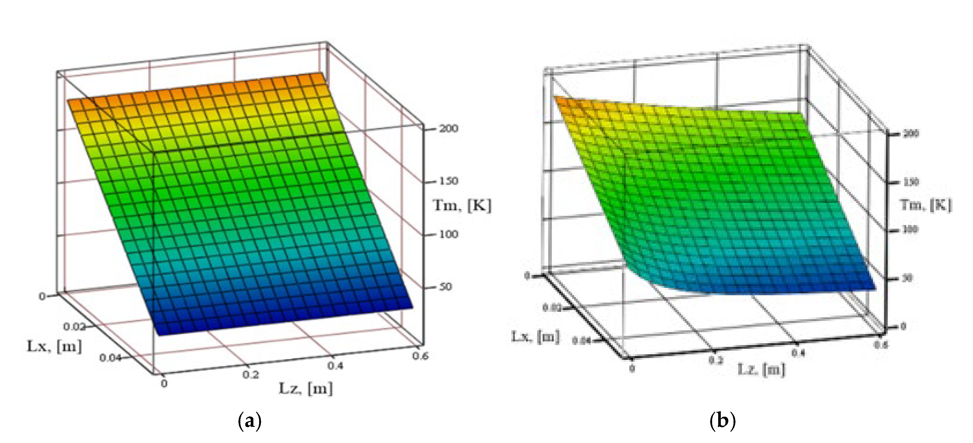
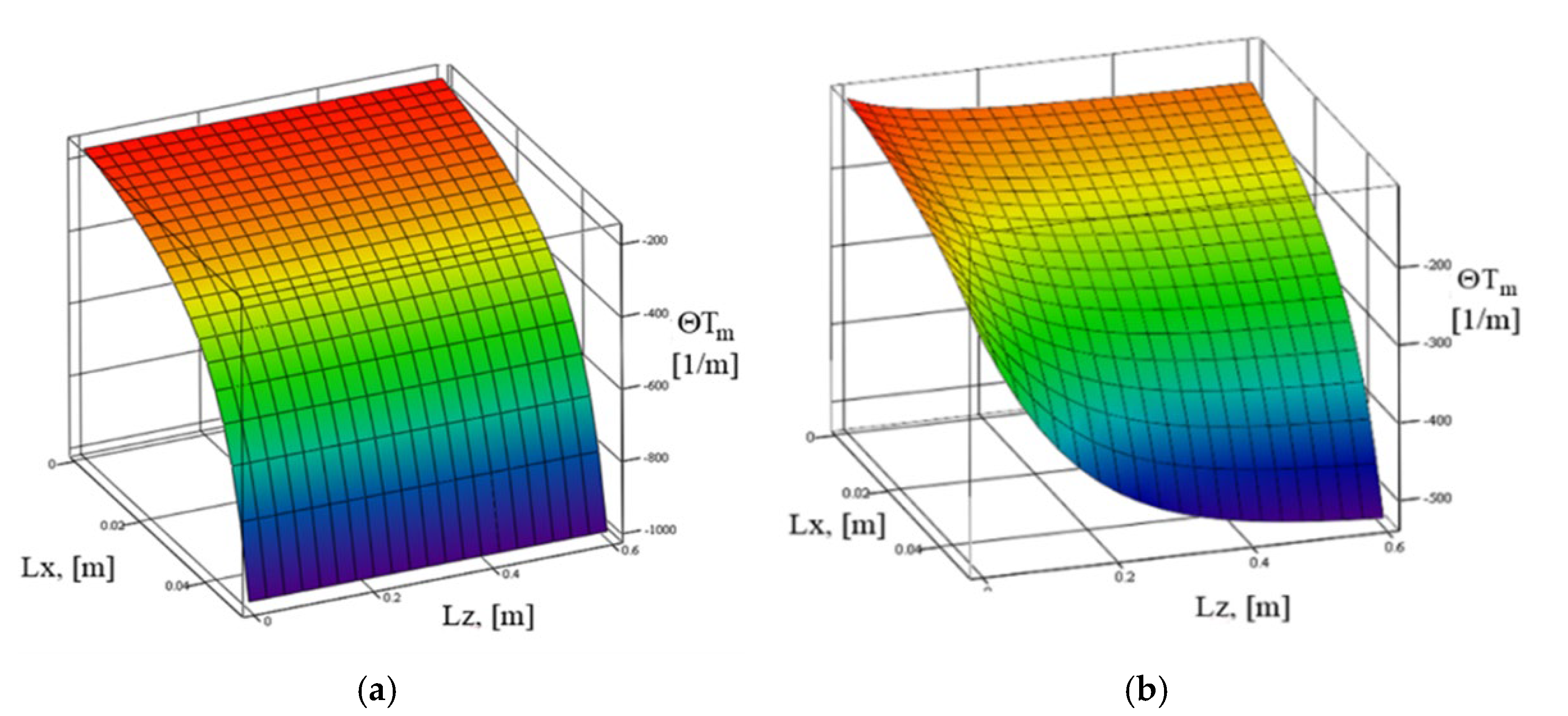
The results of the calculations of the distributions and complexes in the matrix of thermoacoustic devices with different types of heat exchangers, both ideal and real, are shown in Figure 5 and Figure 6.

4. Discussion

To consider the impact of the heterogeneity of heat exchangers’ surface temperature distribution in the matrix on the characteristics of the TAE, when calculating expressions (6) and (9), modified temperature gradient values should be used.
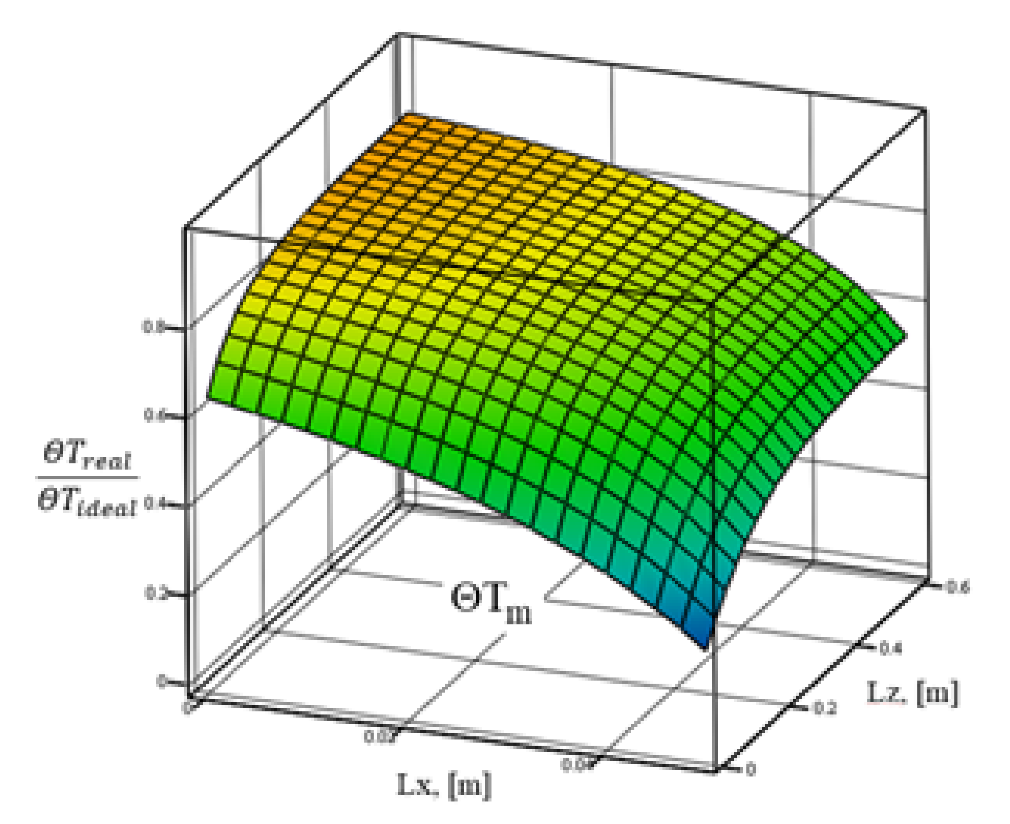
Quantitatively, the influence of the heterogeneity of the temperature distribution inside the matrix of the TAC on the power of the TAE can be estimated using a normalized integral complex, which was obtained by integrating Equation (13) with the volume of the matrix:
Θ T M = 0 l M 0 l Z 1 T m ( x , z ) d T m ( x , z ) d x r e a l d x d z 0 l M 0 l Z 1 T m ( x , z ) d T m ( x , z ) d x i d e a l d x d z ,
The results of the calculation of the ratio in (39) are given in Figure 7. The calculations revealed that in the matrix of a “real” TAE, the distribution of the average integrated matrix gain significantly differed from the distribution in the ideal case.
To verify the obtained results, calculations were made to provide the initial information, and the design and testing data of the thermoacoustic heat-insulating installations of the FP7 project were used [50,51,52]. The results of the calculations showed a good similarity with these experiments and numerical modeling, which allows for the use of the developed technique to take into account the effect of heat exchangers on the characteristics of thermoacoustic engines in the modeling of TAE systems for the use of thermal emissions.
The conducted theoretical research made it possible to provide a scientific justification for the rational principles of creating low-temperature thermoacoustic energy-saving systems. The results of this work allow for the formalization of recommendations for the design and use of low-temperature thermoacoustic energy-saving systems in practice.
Additionally, the implementation of TAHM technologies within energy complexes for waste heat utilization leads to the support of environmental sustainability by lowering the overall heat emissions. The introduction of thermoacoustic technologies in energy-saving systems makes it possible to expand their resource base by including low-temperature and cryogenic heat sources. Expanding the capabilities of energy-saving systems reduces the consumption of extracted carbon fuels, which contributes to the decarbonization of processes related to social production and reduces the emissions of environmentally harmful substances.

5. Conclusions

  • A principal scheme of a power plant with a thermoacoustic energy saving system, desired for the utilization of low-temperature thermal emissions was proposed, the peculiarity of which consisted of the possibility of converting the waste heat of different potentials in the case of using cryogenic fuels;
  • A mathematical model of a power plant with a thermoacoustic energy saving system, which allows for the determination of the effectiveness of the use of a thermoacoustic system for different types of power plants, was synthesized;
  • The original mathematical model of the energy exchange processes between the elements of the thermoacoustic core, namely the heat exchangers, the matrix, and the working body, was created. The model makes it possible to determine the influence of the inhomogeneity of the temperature field on the surface of heat exchangers and the characteristics of thermoacoustic engines;
  • The application of recuperative heat exchangers with "liquid–gas" types of mechanisms in thermoacoustic systems leads to efficiency losses, associated with both the irreversibility of the heat exchange processes and the formation of temperature heterogeneity in the elements of the thermoacoustic core. It was proved that these losses reduce the potential power of the thermoacoustic installations by 1.1-1.3 times;
  • For low-temperature TAEs, it is advisable to apply heat exchangers with high thermal power and even temperatures along the front as evaporators or condensers. It was proved that the recuperative liquid–gas HEX reduces the efficiency of TAEs and their total capacity by 10-35%.
Further research in the field of thermoacoustic energy-saving technologies should be focused on the development of the optimal organization of energy exchange processes between the external heat energy sources and the heat exchange core of thermoacoustic engines.

Author Contributions

Conceptualization, Z.Y., V.K. and M.R.; methodology, V.K., M.R. and R.R.; software, V.K. and R.R.; validation, V.K., M.R. and R.R.; formal analysis, V.K., M.R. and Z.Y.; investigation, V.K., M.R. and R.R.; resources, Z.Y. and R.R.; data curation, V.K., M.R. and R.R.; writing—original draft preparation, V.K, M.R. and R.R.; writing—review and editing, V.K., M.R. and Z.Y.; visualization, V.K. and R.R.; supervision, V.K. and M.R.; project administration, V.K. and M.R.; funding acquisition, Z.Y. All authors have read and agreed to the published version of the manuscript.

Funding

This research received no external funding.

Institutional Review Board Statement

Not applicable.

Informed Consent Statement

Informed consent was obtained from all subjects involved in the study.

Data Availability Statement

Not applicable.

Conflicts of Interest

The authors declare no conflict of interest.

References

  1. Benveniste, H.; Oppenheimer, M.; Fleurbaey, M. Climate change increases resource-constrained international immobility. Nat. Clim. Chang. 2022, 12, 634–641. [Google Scholar] [CrossRef]
  2. Gambhir, A.; George, M.; McJeon, H.; Arnell, N.W.; Bernie, D.; Mittal, S.; Köberle, A.C.; Lowe, J.; Rogelj, J.; Monteith, S. Near-term transition and longer-term physical climate risks of greenhouse gas emissions pathways. Nat. Clim. Chang. 2022, 12, 88–96. [Google Scholar] [CrossRef]
  3. Olmer, N.; Comer, B.; Roy, B.; Mao, X.; Rutherford, D. Greenhouse Gas Emissions from Global Shipping, 2013–2015/N; ICCT: Washington, DC, USA, 2017; 38p. [Google Scholar]
  4. Kornienko, V.; Radchenko, R.; Bohdal, Ł.; Kukiełka, L.; Legutko, S. Investigation of condensing heating surfaces with reduced corrosion of boilers with water-fuel emulsion combustion. In Proceedings of the Integrated Computer Technologies in Mechanical Engineering—2020. ICTM 2020, Kharkov, Ukraine, 29–30 October 2020; Lecture Notes in Networks and, Systems. Nechyporuk, M., Pavlikov, V., Kritskiy, D., Eds.; Springer: Cham, Switzerland, 2021; Volume 188, pp. 300–309. [Google Scholar]
  5. Kornienko, V.; Radchenko, R.; Radchenko, M.; Radchenko, A.; Pavlenko, A.; Konovalov, D. Cooling cyclic air of marine engine with water-fuel emulsion combustion by exhaust heat recovery chiller. Energies 2022, 15, 248. [Google Scholar] [CrossRef]
  6. Yang, Z.; Kornienko, V.; Radchenko, M.; Radchenko, A.; Radchenko, R.; Pavlenko, A. Capture of pollutants from exhaust gases by low-temperature heating surfaces. Energies 2022, 15, 120. [Google Scholar] [CrossRef]
  7. Balcombe, P.; Brierley, J.; Lewis, C.; Skatvedt, L.; Speirs, J.; Hawkes, A.; Staffell, I. How to decarbonize international shipping: Options for fuels, technologies and policies. Energy Convers. Manag. 2019, 182, 72–88. [Google Scholar] [CrossRef]
  8. Global Marine Technology Trends 2030. Available online: https:eprints.soton.ac.uk/388628/1/GMTT2030.pdf (accessed on 1 June 2019).
  9. World Energy Balances 2020 (IEA, 2020). Available online: https://www.iea.org/data-and-statistics/data-product/world-energy-balances (accessed on 12 January 2021).
  10. Thekdi, A.; Nimbalkar, S.; Sundaramoorthy, S.; Armstrong, K.O.; Taylor, A.; Gritton, J.E.; Wenning, T.; Cresko, J. Technology Assessment on Low-Temperature Waste Heat Recovery in Industry; Oak Ridge National Lab.: Oak Ridge, TN, USA, 2021. [Google Scholar] [CrossRef]
  11. Johnson, I.; Choate, W.T.; Davidson, A. Waste Heat Recovery. Technology and Opportunities in U.S. Industry; CS, Inc.: Laurel, MD, USA, 2008. [Google Scholar] [CrossRef]
  12. Thekdi, A.; Nimbalkar, S.U. Industrial Waste Heat Recovery—Potential Applications, Available Technologies and Crosscutting R&D Opportunities; Department of Energy′s (DOE): Washington, DC, USA, 2015. [Google Scholar] [CrossRef]
  13. Radchenko, A.; Scurtu, I.-C.; Radchenko, M.; Forduy, S.; Zubarev, A. Monitoring the efficiency of cooling air at the inlet of gas engine in integrated energy system. Therm. Sci. 2022, 26, 185–194. [Google Scholar] [CrossRef]
  14. Yari, M.; Mehr, A.; Zare, V.; Mahmoudi, S.; Rosen, M. Exergoeconomic comparison of TC (trilateral Rankine cycle), ORC (organic Rankine cycle) and Kalina cycle using a low grade heat source. Energy 2015, 83, 712–722. [Google Scholar] [CrossRef]
  15. Radchenko, A.; Radchenko, M.; Mikielewicz, D.; Pavlenko, A.; Radchenko, R.; Forduy, S. Energy saving in trigeneration plant for food industries. Energies 2022, 15, 1163. [Google Scholar] [CrossRef]
  16. Radchenko, M.; Mikielewicz, D.; Andreev, A.; Vanyeyev, S.; Savenkov, O. Efficient ship engine cyclic air cooling by turboexpander chiller for tropical climatic conditions. In Proceedings of the Integrated Computer Technologies in Mechanical Engineering—2020. ICTM 2020, Kharkov, Ukraine, 29–30 October 2020; Lecture Notes in Networks and, Systems. Nechyporuk, M., Pavlikov, V., Kritskiy, D., Eds.; Springer: Cham, Switzerland, 2021; Volume 188, pp. 498–507. [Google Scholar]
  17. Singh, D.; Pedersen, E. A review of waste heat recovery technologies for maritime applications. Energy Convers. Manag. 2016, 111, 315–328. [Google Scholar] [CrossRef]
  18. Yun, E.; Park, H.; Yoon, S.Y.; Kim, K.C. Dual parallel organic Rankine cycle (ORC) system for high efficiency waste heat recovery in marine application. J. Mech. Sci. Technol. 2015, 29, 2509–2515. [Google Scholar] [CrossRef]
  19. Hoang, A.T. Waste heat recovery from diesel engines based on Organic Rankine Cycle. Appl. Energy 2018, 231, 138–166. [Google Scholar] [CrossRef]
  20. Kalina, A.I. Combined cycle and waste heat-recovery power-systems based on a novel thermodynamic energy cycle utilizing low-temperature heat for power-generation. Mech. Eng. 1983, 105, 104. [Google Scholar]
  21. Yang, Z.; Konovalov, D.; Radchenko, M.; Radchenko, R.; Kobalava, H.; Radchenko, A.; Kornienko, V. Analyzing the efficiency of thermopressor application for combustion engine cyclic air cooling. Energies 2022, 15, 2250. [Google Scholar] [CrossRef]
  22. Radchenko, M.; Radchenko, R.; Kornienko, V.; Pyrysunko, M. Semi-empirical correlations of pollution processes on the condensation surfaces of exhaust gas boilers with water-fuel emulsion Combustion. In Lecture Notes in Mechanical Engineering; Ivanov, V., et al., Eds.; Springer: Cham, Switzerland, 2020; pp. 853–862. [Google Scholar]
  23. Konovalov, D.; Radchenko, M.; Kobalava, H.; Kornienko, V.; Maksymov, V.; Radchenko, A.; Radchenko, R. Research of characteristics of the flow part of an aerothermopressor for gas turbine intercooling air. Proc. Inst. Mech. Eng. Part A J. Power Energy 2021, 236, 634–646. [Google Scholar] [CrossRef]
  24. Yang, Z.; Radchenko, M.; Radchenko, A.; Mikielewicz, D.; Radchenko, R. Gas turbine intake air hybrid cooling systems and a new approach to their rational designing. Energies 2022, 15, 1474. [Google Scholar] [CrossRef]
  25. Rott, N. Thermoacoustics. Adv. Appl. Mech. 1980, 20, 135–175. [Google Scholar]
  26. Wheatley, J.; Hofler, T.; Swift, G.W.; Migliori, A. Understanding some simple phenomena in thermoacoustics with application to acoustical heat engines. Am. J. Phys. 1985, 2, 147–162. [Google Scholar] [CrossRef]
  27. Swift, G.W. Thermoacoustics—A Unifying Perspective for Some Engines and Refrigerators; Acoustical Society of America: Melville, NY, USA, 2002. [Google Scholar]
  28. Tijani, M.E.H.; Spoestra, S. A high performance thermoacoustic engine. J. Appl. Phys. 2011, 110, 093519. [Google Scholar] [CrossRef]
  29. De Blok, K. Low operating temperature integral thermoacoustic devices for solar cooling and waste heat recovery. In Proceedings of the Acoustic-2008 International Conference, Paris, France, June 30–4 July 2008; pp. 18–24. [Google Scholar]
  30. Ward, B.; Clark, J.; Swift, G. Design Environment for Low-Amplitude Thermoacoustic Energy Conversion: Users Guide; Los Alamos National Laboratory: Los Alamos, NM, USA, 2012. [Google Scholar]
  31. Ceperly, P.H. A pistonless Stirling engine—The traveling wave heat engine. J. Acoust. Soc. Am. 1979, 66, 1508–1513. [Google Scholar]
  32. Backhaus, S.; Swift, G.W. A thermoacoustic-Stirling heat engine: Detailed study. J. Acoust. Soc. Am. 2000, 107, 3148–3166. [Google Scholar] [CrossRef] [Green Version]
  33. Kondratenko, Y.; Korobko, V.; Korobko, O.; Kondratenko, G.; Kozlov, O. Green-IT Approach to Design and Optimization of Thermoacoustic Waste Heat Utilization Plant Based on Soft Computing. In Green IT Engineering: Components, Networks and Systems Implementation. Studies in Systems, Decision and Control; Kharchenko, V., Kondratenko, Y., Kacprzyk, J., Eds.; Springer: Cham, Switzerland, 2017; Volume 105, pp. 287–311. [Google Scholar] [CrossRef]
  34. Timmer MA, G.; de Blok, K.; van der Meer, T.H. Review on the conversion of thermoacoustic power into electricity. J. Acoust. Soc. Am. 2018, 143, 841–857. [Google Scholar] [CrossRef] [PubMed]
  35. De Blok, K. Bi-Directional Turbines for Converting Acoustic Wave Power into Electricity. 2017. Available online: http://www.aster-thermoacoustics.com/wp-content/uploads/2015/01/Bi-directional-turbines-Riga.pdf (accessed on 15 April 2021).
  36. Kondratenko, Y.; Serbin, S.; Korobko, V.; Korobko, O. Optimisation of Bi-derectional puls turbine for waste heat utilization plant based on green IT paradigm. In Green IT Engineering: Components, Networks and Systems Implementation. Studies in Systems, Decision and Control; Springer: Cham, Switzerland, 2018; Volume 106. [Google Scholar]
  37. Wakeland, R.S. Heat Exchangers in Oscillating Flow, with Application to Thermoacoustic Devices That Have Neither Stack nor Regenerator. Ph.D. Thesis, The Pennsylvania State University, State College, PA, USA, 2003. [Google Scholar]
  38. Liu, J.; Garrett, S.L. Relationship between Nusselt number and the thermoviscous (Rott) functions. J. Acoust. Soc. Am. 2009, 119, 1457–1461. [Google Scholar] [CrossRef]
  39. Wu, F.; Wu, C.; Guo, F.; Li, Q.; Chen, L. Optimization of a thermoacoustic engine with a complex heat transfer exponent. Entropy 2003, 5, 444–451. [Google Scholar] [CrossRef]
  40. Jin Kan, X.; Wu, F.; Chen, L.; Sun, F.; Guo, F. Exergy efficiency optimization of a thermoacoustic engine with a complex heat transfer exponent. Int. J. Sustain. Energy 2010, 29, 220–232. [Google Scholar] [CrossRef]
  41. Mozurkewich, G. Heat transfer from transverse tubes adjacent to a thermoacoustic stack. J. Acoust. Soc. Am. 1998, 110, 841–847. [Google Scholar] [CrossRef]
  42. Mozurkewich, G. Time-average temperature distribution in a thermoacoustic stack. J. Acoust. Soc. Am. 1998, 103, 380–388. [Google Scholar]
  43. Piccolo, A.; Pistone, G. Estimation of heat transfer coefficients in oscillating flows: The thermoacoustic case. Int. J. Heat Mass Transfer. 2006, 49, 1631–1642. [Google Scholar]
  44. Nsofor, E.C.; Celik, S.; Wang, X. Experimental study on the heat transfer at the heat exchanger of the thermoacoustic refrigerating system. Appl. Therm. Eng. 2007, 27, 2435–2442. [Google Scholar]
  45. Jaworski, A.J.; Piccolo, A. Heat transfer processes in parallel-plate heat exchangers of thermoacoustic devices—Numerical and experimental approaches. Appl. Therm. Eng. 2012, 42, 145–153. [Google Scholar]
  46. Jaworski, A. Editorial for Special Issue: “Heat Transfer Processes in Oscillatory Flow Conditions”. Appl. Sci. 2017, 7, 994. [Google Scholar] [CrossRef]
  47. Herman, C.; Chen, Y. A simplified model of heat transfer in heat exchangers and stack plates of thermoacoustic refrigerators. Heat Mass Transf. 2006, 42, 901–917. [Google Scholar] [CrossRef]
  48. Paek, I.; Braun, J.E.; Mongeau, L. Heat transfer coefficients of heat exchangers in the thermoacoustic coolers. In Proceedings of the International Congress of Refrigeration, Washington, DC, USA, 17–22 August 2003; pp. 1–8. [Google Scholar]
  49. Hausen, H. Heat Transfer in Counterflow, Parallel-Flow, and Cross-Flow; McGraw-Hill: New York, NY, USA, 1983; 515p. [Google Scholar]
  50. Thermo Acoustic Power (TAP) an Industriële Restwarmte naar Elektriciteit SBIR Fase 1 Haalbaarheidsstudie. Available online: https://docplayer.nl/2251837-Thermo-acoustic-power-tap-van-industriele-restwarmte-naar-elektriciteit-sbir-fase-1-haalbaarheidsstudie.html (accessed on 15 April 2021).
  51. Eindrapportage Fase II Thermo Acoustic Power (TAP) Conversie Industriële Restwarmte naar Elektriciteit. Available online: http://www.aster-thermoacoustics.com/wp-content/uploads/2012/04/Eindrapportage-TAP-SBIR09313.pdf (accessed on 15 April 2021).
  52. Final Report Summary—THATEA (Thermo Acoustic Technology for Energy Applications). Available online: https://cordis.europa.eu/docs/results/226/226415/final1-final-report.pdf (accessed on 15 April 2021).
  53. Kuznetsov, V. Justification of efficiency of plain shaped heat exchange surfaces to increase the compactness of power plants. East. -Eur. J. Enterp. Technol. 2020, 6, 17–24. [Google Scholar] [CrossRef]
  54. Chen, W.H.; Wang, C.M.; Huat Saw, L.; Hoang, A.T.; Bandala, A.A. Performance evaluation and improvement of thermoelectric generators (TEG): Fin installation and compromise optimization. Energy Convers. Manag. 2021, 250, 114858. [Google Scholar] [CrossRef]
  55. Kruzel, M.; Bohdal, T.; Dutkowski, K.; Radchenko, M. The Effect of Microencapsulated PCM Slurry Coolant on the Efficiency of a Shell and Tube Heat Exchanger. Energies 2022, 15, 5142. [Google Scholar] [CrossRef]
  56. Radchenko, M.; Radchenko, A.; Radchenko, R.; Kantor, S.; Konovalov, D.; Kornienko, V. Rational loads of turbine inlet air absorption-ejector cooling systems. Proc. Inst. Mech. Eng. Part A J. Power Energy 2022, 236, 450–462. [Google Scholar] [CrossRef]
  57. Cebeci, T.; Bradshaw, P. Physical and Computational Aspects of Convective Heat Transfer; Springer: Berlin/Heidelberg, Germnay, 1984. [Google Scholar]
Figure 1. Principal scheme of low-temperature thermoacoustic heat recovery system.
Sustainability 14 12306 g001
Figure 2. Heat exchange unit of the thermoacoustic apparatus, showing its core and design components: (a) thermoacoustic core; (b) scheme energy flows in the heat exchange unit.
Sustainability 14 12306 g002
Figure 3. Double amplitude of oscillating motion depending on the operating frequency at different pressures, with temperature 298 K and helium.
Sustainability 14 12306 g003
Figure 4. Diagram of the mathematical model.
Sustainability 14 12306 g004
Figure 5. Temperature distribution in the TAE matrix: (a) homogeneous distribution of temperatures on the surface of heat exchangers; (b) TAE with real recuperative heat exchangers.
Sustainability 14 12306 g005
Figure 6. Distribution of specific temperature gradient in the TAE matrix: (a) with a homogeneous distribution of temperatures in heat exchangers; (b) real regenerative heat exchangers.
Sustainability 14 12306 g006
Figure 7. Ratio in the TAE matrix with recuperative heat exchangers.
Sustainability 14 12306 g007
Table 1. Abbreviations.
AbbreviatureElement
GHGGreenhouse gas
ICEInternal combustion engine
HEXHeat exchanger
SPPShip power plants
TAThermoacoustic
TAEThermoacoustic engine
TARThermoacoustic refrigerator
TAHMThermoacoustic heat machine
TACThermoacoustic core
TATGThermoacoustic turbo generator
LNGLiquid nutrition gas
LNH3Liquid ammonium
WHRSWaste heat recovery system
Table 2. Temperature of waste heat coolants of ship ICEs.
Coolant, KLow-Speed EngineMedium-Speed EngineCharacteristics
Exhaust gas481–530 K500–690Low
temperature
Charge air400–490380–470
Jacket cooling 355–360360–370
LNG fuel111Cryogenic
LNH3 fuel250
Publisher’s Note: MDPI stays neutral with regard to jurisdictional claims in published maps and institutional affiliations.