Article

Sustainability of Water Resources in Karst Undermined by Tunneling: A Case Example

1
2TDK, Ltd., 1000 Ljubljana, Slovenia
2
IRGO, Institute for Mining, Geotechnology and Environment, 1000 Ljubljana, Slovenia
*
Author to whom correspondence should be addressed.
Sustainability 2022, 14(2), 732; https://doi.org/10.3390/su14020732
Submission received: 14 September 2021 / Revised: 31 December 2021 / Accepted: 6 January 2022 / Published: 10 January 2022

Abstract

:
Water resources in karsts are scarce due to the high cavernosity in the otherwise low-permeability limestone rock mass. The highly variable porosity and transmissivity of karst aquifers are caused by a network of channels, caverns, and caves that typically act as water-bearing, connected vessels. Tunneling in a karst environment can severely deplete an aquifer and undermine the sustainability of water resources over the long term. A research study was carried out to elaborate and develop measures for the sustainable preservation of the water resources in a Slovenian karst, in which two approximately 7 km-long tunnels will be driven as part of the construction of the new Divača–Koper railway line. Hydrogeological site investigations were carried out with an aim to evaluate the transmissivity and spatial spreading of the karst aquifer along the route of the tunnels, including the observation of the long-term variation of the groundwater levels and trace experiments. The main findings, which are presented in this paper, were used to develop a methodology for the selection of adequate measures for tunnel construction with an aim of ensuring the sustainability of water resources in karst aquifers. The construction measures comprise limiting the inflows using injection grouting, obscuring the groundwater intake by undrained sections of the tunnel, and constructing bypasses around the tunnel to preserve the current groundwater flow regime. The presented methodology of dynamically accommodating the preventive measures to the actual hydrogeological conditions onsite is generally applicable for common cases in which the state of the karst aquifer could not be pre-determined with a sufficient accuracy of tens of meters to a meter. The spatially and temporally continuous hydrogeological investigations and decision-making charts to reduce the tunnelling’s impact on the karst aquifer are explained in detail in this paper.

1. Introduction

According to some estimations, karst regions cover 7–12% of the Earth’s continental area, and their aquifers are at least a partial source of drinking water supply to almost one quarter of the world’s population [1]. In Slovenia, this percentage is even higher as almost 50% of the surface area is karstified and more than 50% of the drinking water comes from groundwater from karstic aquifers. Globally, stress on groundwater resources has increased dramatically in recent decades in terms of water quantity due to the fact of excessive irrigated agriculture, infrastructure development, and different forms of pollution [2]. Planning and extensive research may only lessen the risk of the impact but can never totally ensure a positive final result whatever the work we undertake in karsts [3]. Therefore, a methodology integrating structural, geological, hydrogeological, and karstological data as well as groundwater protection demands was developed to obtain the sustainability of the water resources undermined by the new Divača–Koper railway line. The development of the methodology started in 2007 following the early stages of the planning procedure and continued throughout additional field investigation over the following decade; the need for this was identified by the described method and is extending into and beyond the end of the construction phase, which is currently ongoing. As the method is aimed at finding solutions to sustain human and ecological needs (i.e., drinking water protection) it can be implemented on any given tunnel construction within groundwater protection areas.
It is widely acknowledged that disturbance of the karst aquifer caused by excavation of the tunnel is to a certain degree inevitable. Tunneling in interaction with the aquifer is based on the principle of “the combination of drainage and interception”, which means that tunnel drainage can effectively reduce water pressure on the structure; thus, destruction of the groundwater environment and the loss of groundwater resources cannot be ignored [4] and must be prevented up to the required level.
Apart from the classical works of Milanović [5] and Bonacci [6] on the topic of tunnel construction in karstic conditions and the impact it has on karst hydrology, there have been a significant number of contributions to this topic over the last two decades, adding up to a relevant source of tested knowledge. They can be divided into several categories: (a) the descriptive, (b) those that deal with water inrush and the prevention of ground collapse accidents during tunneling, and (c) those that deal with the environmental impact. In the first category, relevant to this work are the contributions of Knez and Slabe [7], who provided a description of the types and frequency of occurrence of karstic phenomena found in Slovenian karst, and Garašić [8], who gave a comprehensive description of the construction problems with caves during tunneling in Dinaric Karst in Croatia. In the second category, dealing with the hazards of water inrush and ground collapse, which pose serious threats to the safety of the tunnel, are the works of Kang et al. [9], among others, on the karst cave treatment and waterproofing strategy for the TBM tunneling in the urban metro tunnel in Jinan City in China, and Zhang et al. [10] on the risk assessment of water inrush in tunnels in carbonate karst terrain. In the same category are the works of Day [11], on the karstic problems in the construction of Milwaukee’s deep tunnels, and Alija et al. [12] on the systematization of the problems and design solutions associated with tunnel construction in karst rock masses in the case of the Gavarres tunnel in Spain. As the solution methods found in the literature are often only locally applicable or are too general, the issue of karst hydraulic hazards needs to be controlled by carrying out an investigation during tunnel construction, comprising predrilling along the whole karst route and extensive use of borehole geo-radar for early detection of water-bearing karst features. In the category of the environmental impact of tunnels constructed in karsts affecting the saturated zone and the conduit system are the contributions of Gisbert et al. [13] and Shen et al. [14], on different case examples dealing with the environmental and hydrogeological impact, and Neukomm et al. [15] on the adaptation of the tunnel construction to hydrogeological conditions in a karst region. Jeannin et al. [16] and Malard et al. [17] used the case example of the karstic Brunnmühle spring system in Bernese Jura, Switzerland, to develop a methodology to assess the karst hydraulic hazards in tunneling and to determine the impact of a tunnel on a karst aquifer. The majority of this research was presented through case studies as the tremendous heterogeneity of karst systems does not provide much room for generalization. In spite of this, Jeannin at al. [18] gave a valid contribution for the conceptualization of karst hydrogeological systems, and Filipponi et al. [19] provided comprehensive recommendations, known as the KarstALEA approach, for the prediction of karst-related hazards in underground work. It can be observed that the vulnerability of a karst aquifer, which stems from its hydrogeological complexity and the fact that it can be significantly undermined by tunneling, is a well-studied topic. However, there is a lack of scientific and technical literature that addresses the impact of tunneling on potential long-term groundwater losses in terms of the sustainability of water resources, which is the topic of this paper.
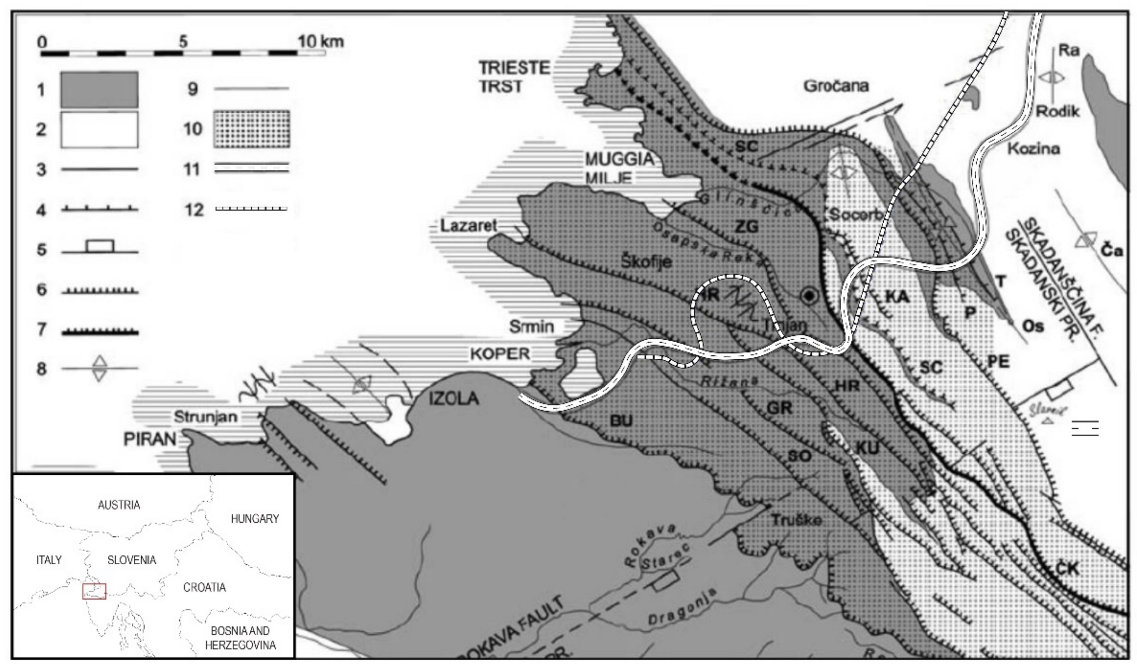
The research presented here is intended to address this deficiency by presenting a method developed for the presented case example, which was studied for the protection of a classic karst aquifer, Rižana, intersected by the tunnels of the new Divača–Koper railway line. An overwhelming majority of the water supply for the 44 km-long Slovenian Adriatic Sea shore, narrowly constricted between Croatia in the south and Italy in the north, comes from a karstic aquifer located in the mainland. The city of Koper, home of the only Slovenian seaport and an important industrial, cultural, and tourist center, is supplied by the Rižana water supply network. The number of water consumers in the network is approximately 85,000 people, but it is highly dependent on the tourist season, when it increases up to 120,000. The Rižana water supply system mainly faces supply problems in the summer months when water consumption is at its highest while the abundance of the Rižana water source is at its lowest. As a result, there is a negative water balance, leading to emptying of the water reservoirs, which is reflected in low water quality and interruptions in water supply to consumers. For the given situation, sustainability of the water resources in the Slovenian karsts is the key issue for the coastal region, bearing a major societal impact. The construction of the new railway line Divača–Koper was therefore carefully assessed in terms of the interaction between the tunnel construction and the karst water resources.
The new railway route overcomes a 400 m height difference between the karst plateau and sea level along the 27.1 km-long route. The required maximum inclination of the railway track of 1.7% dictates that almost 75% of the railway line runs underground. The main challenge presents the construction of the two twin tunnels, T1 (6.7 km) and T2 (6.0 km). The total length of the main and service tubes for both tunnels is some 25.4 km, while some 21 km runs through the karstic aquifer. The size of the excavation profile for both the main and the service tubes is approximately 75 m2. There are also 13 cross-passages along tunnel T1 and 12 along tunnel T2, which are distributed at approximate distances of 500 m. The passages are necessary to allow access to rescue vehicles and to host power supply stations. It was recognized that a substantial network of new channels introduced by tunnels T1 and T2 to the karstic aquifer poses a considerable threat to the existing groundwater flow regime, with potential detrimental effects on the water supply of the coastal region in the long term.
The Rižana catchment was protected by Slovenian legislation in 2005 by a separate Decree [20], which initially did not allow the drainage of water from the karst aquifer by construction of transport infrastructure. This effectively meant that fully watertight tunnels had to be built along their entire lengths. However, this was regarded as unfeasible as watertight tunnel lining must withstand the full hydrostatic groundwater pressures, which can compromise buildability. In that sense, the junctions between the cross-passages and main tunnel tubes are particularly vulnerable. It was recognized that for expected water pressures in excess of 15 bars, it was practically impossible to achieve reasonable construction costs and technical feasibility at the critically affected parts of tunnels T1 and T2.
In order to meet the groundwater protection needs and at the same time be able to construct a tunnel, further technical solutions were sought to limit the outflow of groundwater with sufficient water pressure reduction to assure tunnel safety. A hydrogeological risk analysis was carried out to assess the degree of impact of the tunnels on groundwater balance and quality. The basis for the adjustment of the legislative amendments from 2014 and 2015 was the determination of the level of groundwater protection, which was proven to be sufficient by the risk assessment. This resulted in the formulation of a new decree which allowed groundwater drainage in areas of low aquifer transmissivity. Thus, a compromise was achieved for tunnels to be constructed in watertight forms only in areas in which the outsourcing of the karstic aquifer would otherwise be unacceptably high. There are examples of watertight tunnels, such as the Hallandsas in Sweden [21], which were built at significant costs and at prolonged construction times. In the case of the Hallandsas tunnels, a balance of the feasibility of the tunnel construction and the sustainability of the water resources was not achieved, resulting in profound financial and societal impact [22].
For tunneling in the Slovenian karst aquifer, apart from overcoming the integrated risks and hazards in the short term, the real challenge was to find solutions to simultaneously protect the tunnel from high groundwater pressures and to achieve sustainability by draining the aquifer up to the allowable level in the long term. The methodology to determine the appropriate construction measures presented in the continuation was based on extensive works that incorporated input from geological, hydrogeological, and speleological site investigations, which were acquired as part of the project study [23]. The presented methodology is based on the recognition that the nature of the hydrogeological data and of new karstic information evolves continuously as real facts are revealed by the tunnel construction in progress. As will be explained later, the purpose of this concept is to aid the process of decision making so that previously defined tunnel-construction measures are subjected to change in order to solve newly recognized problems. In that sense, the methodology presented here follows the philosophy of the third stage of the KarstALEA approach [19], with a distinction that is not only used to reduce hazard but primarily to obtain the sustainability of water resources in the long term, while assuring tunnel safety.

2. Geological and Hydrogeological Conditions along the Tunnel Routes

The determination of the hydrogeological conditions of the aquifer in which the tunnels are to be constructed was based on large-scale geological structural modeling and extensive geological and hydrogeological investigations, including 3D structural geological mapping. The latter proved to be a valuable support in the spatial extrapolation of the possible high permeability and the highly karstified zones in the rock mass. It was acknowledged that karstification occurs predominantly in areas with a predisposition towards groundwater flow, such as tectonic discontinuities or contacts of limestone with strata of low permeability. The need for additional field investigation was identified based on this supposition and oriented towards the areas for which the lateral or vertical extent of a possible karstified zone (thrusts, faults, stratigrafical contacts, etc.) was not known to the required precision.

2.1. General Tectonic and Stratigraphic Layout

The new Divača–Koper railway line crosses the border area between the Istria peninsula, belonging to the Dinaric foreland, and the Kras (Slovene word for Karst) that belong to the External Dinarides. This imbricated geological structure, formed between the Eocene and Oligocene, is known as Karst Edge or Karst Rim. The main feature of the Karst Rim is the sequence of thrust and sub-thrust faults overlapping the Cretaceous, Paleocene, and Lower and Middle Eocene carbonate beds, with a transition to the marl and flysch rocks of the Eocene age. The faults were active in post-Miocene times due to the under-thrusting of the Istrian peninsula under the mainland External Dinarides [24].
This geomorphologic belt is intermittently exposed from the Gulf of Kvarner in Croatia to the Gulf of Trieste in Slovenia and Italy (see Figure 1). The tectonic and stratigraphic evolution of this area is the result of the carbonate sedimentation on the Adriatic–Dinaric carbonate platform from the Late Triassic onwards. With the degradation of the carbonate platform and the deposition of the clastic flysch in front of the advancing Dinaric collision, the thrusting and sub-thrusting system was formed in the foreland basin.
The overlap of thrust faults formed ideal conditions for the formation of the karst features in the Slovenian karst plateau, which extends east of the Karst Rim. In the typical sequence, the underlying flysch acts as an aquitard, holding the significant water retention to the water-bearing limestone above. As a result, a substantial karstification of the limestone is present at the carbonate platform, as seen in the well-known Postojna and Škocjan caves, which are among the biggest cave systems in Europe. Additional karstification occurs along sub-vertical faults and fractures, giving way to the vertical runoff of almost the entire net rainfall [20].

2.2. Karstification

As shown in Figure 1, the new railway line crosses the Karst Rim in proximity to the existing motorway. The construction of the motorway was instrumental in obtaining the geological and hydrogeological information relevant to the new construction [7]. However, the motorway layout is spatially placed much higher than that of the railway. Additional site investigations of the karst features revealed zones of different levels of karstification along the railway route. This is schematically shown in Figure 2 for tunnel T1. It can be seen that most of the tunnel runs through the carbonate beds of different geological ages associated with different levels of karstification. Passing through nine different sections (A–I), tunnel T1 features two karstification levels in terms of the expected cavity diameter (up to 5 m and up to 10 m), as indicated in the figure. Tunnel T1 has transition fault zones and sections in the flysch geological sequence (J), which is some 0.7 km long.

2.3. Geological and Hydrogeological Profile

Extensive areal karstological and hydrogeological studies of the Slovenian karst were carried out on different occasions for the water supply needs of the coastal region and most recently during the investigations for the construction of the motorway [25], which follows approximately the same route as the new railway line. The overall understanding of the hydrological conditions was already known; so, the extended and detailed site investigation works were focused on the area along the routes of tunnels T1 and T2. These were carried out on two occasions. The initial site investigation, which was carried out in 2007, comprised 11 boreholes and was used to initially determine the geological structure and material parameters of the rock mass. Some of the boreholes were instrumented with piezometers for long-term observation of the variation of the groundwater table. Once the complexity of the hydrogeological conditions was apprehended, the initial site investigation was complemented with additional field investigations, which were carried out in 2018. These included the drilling of ten structural boreholes with depths of 150–350 m, four of which were intended for supplementary investigations for the T1 tunnel, and five were boreholes for tunnel T2. With five boreholes from stage one of the investigation, the total number of investigation boreholes for tunnel T1 was nine, approximately one per 0.75 km of tunnel run. Most of these boreholes were supplied with equipment for the monitoring of the hydrogeological and hydrological characteristics of the aquifer so that valuable data were provided for the assessment of some 14 years of groundwater regime along the route of the tunnel.
Due to the abundance of data, the results of the measurements presented here will be solely focused on tunnel T1 for clarity. The results for tunnel T2 are to a certain degree different, but the addressed hydrogeological issues are treated with the same methodology; so, the conclusions are the same. The distribution of investigation boreholes for tunnel T1 along the longitudinal geological profile and the groundwater level along the route of tunnel T1 are given in Figure 3.
The interpretation of the structural geology along the tunnel route, shown in Figure 3, shows that most of the T1 tunnel will be excavated within limestone strata of the Cretaceous, Paleocene, and Eocene ages. There were no physical discontinuities in the form of apertures within the strata; so, sub-vertical cracks were the most important element for the formation of the initial horizons and the karst channels. Cretaceous and Paleocene limestone includes a significant proportion of organic matter, which means that the process of dissolution in these layers is more extensive and even more bound to fissure zones or cracks. The findings so far show that more developed karst channel networks are expected at this location, mainly in the Eocene and Cretaceous limestone strata. In the Paleocene strata, the limestone karst channels appeared more locally limited, but this is less so near the sinkholes or drainage zones [23].

3. Measurements and Interpretation of Results

3.1. Tracer Tests

The most reliable information on the directions and characteristics of the underground flow of karst water was obtained through the tracer tests. Given the performed tracer tests and the shares of runoff to individual springs, it was concluded that there would be no significant trans-boundary hydrogeological impacts on Italy or Croatia. Based on the results of the tracking of the underground flow of the river Reka, it was concluded that in the northern part of the tunnel T1, groundwater flows towards the springs of the river Timava, which does not belong to the Rižana confluence. Tracing in the southern part of the tunnel T1 by injection in borehole T1-8 confirmed the lateral flow towards the Boljunec spring of the Timava basin. Opposite to tunnel T1, the majority of the water flow in the area of tunnel T2 is directed towards Rižana and only a small fraction to the Timava basin. Significantly, some 0.9 km of T2 is located directly within the Rižana springs protection zone.
The results of the tracer tests indicated that there could be significant effects on the quantitative status of the springs, especially Rižana, which was of the most interest. Due to the large length of the tunnels within the aquifer and their course below the groundwater level or in the zone of groundwater fluctuations, the drainage caused by the tunnels could lead to a partial redistribution of the karst groundwater flows. It was estimated that in the most critical part of the year (i.e., during the summer drought), the impact of the tunnel drainage would be approximately 2.5% of consumption. Despite this seemingly small percentage, given an average consumption of 200 L per person per day, this figure represents a water supply for about 3200 people, which is a significant part of the population of the Slovenian coastal region.
In a wider sense, it is considered a high possibility that significant and rapid drops in pressure and the draining of individual caverns caused by tunneling are likely to lead to a rearrangement of the water flow patterns in the aquifer. In turn, the abundance of the present karst springs would be impoverished and faster, larger, and muddier outflows from the springs during high rains could be expected. The flow from the area to some contributing karst springs, which can possibly be undermined by tunnel construction, occurs mainly by overflows during high water levels. These overflow mechanisms must be preserved, otherwise the unsustainable depletion of the karst springs in the long term might occur.

3.2. Long-Term Monitoring of Groundwater Levels

The results of the monitoring of the groundwater levels along the route of tunnel T1 for the period of August 2010 to August 2021 are shown in Figure 4. Observing the groundwater level from left (east) to right (west), in the direction of the rising chainage (from chainage km 0 + 000 to km 1 + 750; see Figure 3 for better orientation), the water table is below the level of the tunnel. The observed water level in piezometer T1-12/17 was stable some 20 m below the tunnel level, but during the slug test, the presence of a cavern at a depth of approximately 40 m below the ground level (551.34 m ASL) was positively identified. The next borehole, T1-7, also indicates that the base level of the karst groundwater is below the level of the tunnel by some 40 m at this location, but during downpours, the groundwater in the piezometer dramatically rose at a rate of 68.80 m per hour some 100 m above the tunnel level, so that the total range of level rise was 140 m. It can be concluded that at this section (from chainage km 1 + 750 to km 2 + 500), the tunnel runs through a cave system acting as connected vessels. This cave system belongs to an epiphreatic zone or floodwater zone, which is the intermediate zone between the vadose above and phreatic zone below. It can be seen in Figure 4 that this zone is regularly flooded (15 times between 2011 and 2012), while in the last several years the water never dropped below the tunnel level. Obviously, the construction of tunnel T1 along this section will be a significant challenge, especially as the water pressures and inflows are expected to be relatively high.
In the central part of the syncline, at the section between chainages km 2 + 500 and km 3 + 750 (Eocene layers, see Figure 3), the groundwater level measured in borehole T1-13/17 was slightly variable but not exceeding some 40 m below the level of tunnel. This looks significantly more favorable for tunnel construction, but this is also the area of the highest probability of the occurrence of karst zones, in which the overflow of high karst waters cannot be excluded.
Further on, in the piezometers T1-8 and T1-14/17 (section from chainage km 3 + 750 to km 6 + 000), the groundwater level prevails between 25 and 15 m above the tunnel level but never exceeds 40 m and 30 m, respectively. This strongly indicates some karst overflow features at these locations (bottlenecks) but also means that large amounts of karst groundwater are stored or flow in this pressure range above the tunnel elevation. At this section, the level in borehole T1-14/17 was stable at some 35 m below the tunnel level.
During slug tests on borehole T1-13/17, the cavern was confirmed at the tunnel level, some 133 m below the ground (392.68 m ASL), on two separate occasions. Rapid pressure increases were also recorded at boreholes T1-14/17, T1-10/17, and T1-15/17 but to a much lesser extent than in T1-7/10, namely between 5–7 m/h. In the area of the flysch rocks (section from chainage km 6 + 000 to km 6 + 700), both the highest and the predominant level was some 60 m above the tunnel level, at borehole T1-15/17. Due to the low permeability of the flysch rocks, this will have no significant impact on the tunnel water intake during construction.

4. Characteristics of Karstic Aquifer and Solutions to Preserve Water Resources Undermined by Tunneling

Technical solutions to preserving water resources in karst aquifers must consider the strong subsurface hydraulic heterogeneity of the karstified rocks [26]. The characteristics of karst aquifers are briefly summarized in this section to illustrate the type of technical measures which were governed by them to prevent the long-term outflow of groundwater caused by tunneling.

4.1. Characteristics of Karstic Aquifer

The issue of permanent water intake is determined by the amount of rock mass transmissivity along the certain section of the tunnel. The transmissivity is dependent on the thickness of the aquifer and on the type and magnitude of the conductivity of the rock mass. In a karstic aquifer, there is an interplay of matrix, fracture, and conduit (e.g., the flow through the karstic cavities) porosity [2]. This is schematically shown in Figure 5, which presents an outline of karstified rock mass conductivity [27]. As seen in the figure, the porosity of the karstic aquifer can be matrix (with low fracturing and an absence of karst formations), fracture (predominant in relation to the matrix in the absence of karst formations), and conduit (through karst formations where the predominant water flow is).
The conductivity of a karst aquifer is governed by a markedly localized increase in the porosity of the tectonically affected and/or karstic zones. The pressure wave propagates at a rate that depends on the resistance (inverted permeability) of the porous medium during the infiltration of precipitation. As a result, at relatively short distances along the tunnel route, rapid jumps in groundwater pressures can be expected. This process is present along the fault zones and preferential outflow paths through cavities, which occur predominantly in the vertical direction. It is evident that such a localized system of pressures would act along the tunnel route at certain sections. For example, as seen in Figure 4, as a result of a dominance of conduit and/or fracture porosity, groundwater levels (e.g., piezometer in T1-7/10) oscillate up to 140 m after several hours of precipitation. On the other hand, other piezometers showed medium or low sensitivity to precipitation, indicating dominance of matrix or matrix-to-fracture porosity, respectively.
The sustainability of the water resources of the aquifer is governed by the adequate technical measures developed in response to the different types of rock–mass porosity which may occur along the tunnel route. The aim of the study was to develop a methodology for the application of technical measures to minimize, or at best significantly reduce, the impact of tunnel construction on the aquifer. The following design solutions for tunnel variants and associated technical measures were anticipated:
(a)
Construction of watertight (i.e., undrained) tunnel sections to counteract impact on high fracture and matrix porosity and consequent water bearing (porosity type 1, high transmissivity, high flow, and low water pressures);
(b)
Construction of drained tunnel sections in which matrix porosity is low and outsourcing of groundwater will be low (porosity type 1, low transmissivity, low flow, and high water pressures);
(c)
Construction of bypass channels to neutralize the impact on conduit porosity and prevent redistribution of conduit flow (porosity types 2 and 4, high transmissivity, high flow, and high water pressures);
(d)
Use of injection grouting to reduce the fracture and matrix porosity and permeability at the sections in which the construction of a watertight tunnel is not possible or feasible (porosity type 3, high transmissivity, high flow, and high water pressures);
(e)
Establishment of transition zones for drained/undrained variants to conform to frequent interplay of different porosity types 1 to 4 and high water pressures.
The distribution of the different design solutions along the tunnel route that lead to the development of different tunnel variants is also given in Figure 3. The tunnel variants and different measures are described in more detail below.

4.2. Drained Tunnel Sections

Construction of drained tunnel sections is anticipated in low permeability zones in which the impact of tunnel construction on the aquifer is low and within the acceptable limits. The drainage of the tunnel is obtained by a central 500 mm drainage pipe that is fed by two side drainage pipes 250 mm in diameter.

4.3. Undrained Tunnel Sections

˝Undrained˝ or watertight sections are anticipated at locations in which the complete prevention of water intake from the aquifer is necessary, and the maximum hydrostatic pressures are below 10 bars. For the “undrained” sections, the tunnel secondary lining must retain the full hydrostatic groundwater pressures. For this reason, the tunnel was shaped to be almost circular, and the lining was dimensioned to take 100 m (i.e., 10 bars) of the water column pressures, determined as the upper mark for tunnel buildability. Apart from the aim of preventing depletion of the groundwater resources in the long term, the undrained sections are needed to counteract the rapid oscillations in the water table that can cause the temporary inadequacy of the tunnel drainage capacity.

4.4. Use of Injection Grouting

Rock grouting is regarded as the key technological method for successful tunnel construction within water-bearing rock [28]. It is particularly important as a tool to control water inrushes during tunnel construction within the karstic environment [4] but also to preserve water resources by reducing inflow [29]. Rock grouting should be carried out to reduce the permeability of the rock in the immediate vicinity of the tunnel (i.e., some 4 m) [30] to the extent that: (a) it allows the reception of groundwater for the drained tunnel up to the allowable limits and/or (b) it allows the uptake of the hydrostatic pressures of groundwater for the undrained tunnel. Relative to the schedule of the tunnel excavation, two types of grouting are anticipated [31]: (a) pre-grouting, which aims to limit water inflows into the tunnel during excavation and enables the construction of a drained variant in the area with water pressures higher than 10 bars, and (b) post-grouting, which aims to reduce the permeability of the rock mass well after the excavation of the tunnel. At any rate, grouting is seen as the only way to enable a reduced intake of water from the aquifer at locations in which the groundwater pressures are greater than 10 bars. Additionally, grouting will be used for other purposes, such as to consolidate strongly fractured rocks and karst formations filled with sediments, as an aid to constructing bypass channels, and to improve the rock mass at the transition zones between the drained and undrained sections [32]. The grouting of the rock will be carried out with an injection mass of different compositions (cement mortar, microcement cement mortar, polymer injection mass, etc.) under a suitable pressure in a predetermined zone as appropriate [33].
The pre-grouting will be carried out from fan-shaped boreholes in the area in front of the top heading, as schematically shown in Figure 6. The grouting of the entire tunnel ring is to be performed at the front of the top heading with a fan-shaped arrangement of boreholes with a diameter of 51 mm, a length of 21–22 m, and a gradient of 13° from the horizontal at the top of the tunnel to a slope of 22° from the horizontal at the bottom of the tunnel. The pre-grouting progression step, needed to ensure adequate rock thickness with reduced permeability, would be carried out every 4 m.
The post-grouting will be carried out from the already excavated tunnel, well behind the top heading. It is performed as a corrective measure to further reduce the permeability of the rock mass if the pre-grouting was not fully successful. Moreover, post grouting will be used predominantly in the epiphreatic zones in which water was not detected during the excavation, if there was no need for pre-grouting. In each phase of post-grouting, 23 boreholes, 4 m long and with a diameter of 51 mm, are to be drilled by means of impact rotary drilling every 1.5 m at a particular section. The described layout and the length of the boreholes, schematically shown in Figure 6, ensure a 4 m thick ring of rock with reduced permeability around the entire cross-section.

4.5. Construction of Bypass Channels

The systems of cracks and karst caverns are expected to occur mainly at the fault zones, which are predominantly sub-vertical, but also at the thrust zones, which are predominantly sub-horizontal. The likely intrusions of karst groundwater from the karst conduits are anticipated between geological units and between the transition layers. The appearance of karst cracks and caverns, especially along the lithological boundaries, is expected at the sizes and frequencies shown in Figure 2. If the tunnel route clashes with these water conduits, the groundwater bypasses will be excavated, so that the network of cave spaces and channels remains uninterrupted. The bypass should be constructed in such a way as to enable the flow of groundwater with a maximum 10% reduction in transmissivity. The groundwater bypasses should be also excavated within the epiphreatic zone with a constant or occasional flow of groundwater. Only karstic phenomena filled in by sediments, which are obviously not groundwater conduits, will not be bypassed. There is no general solution for the construction of the bypass channels, as each of them has to be tailor-made for the boundary conditions formed by the clashed karst phenomena and the tunnel layout at a given location.

4.6. An Interplay of Undrained, Drained, and Grouted Tunnel Sections

The drained sections of the tunnel must be constructed in the areas of the cross-passages between the tubes, as the junctions between them and the main tubes cannot efficiently take on elevated groundwater pressures. In order to reduce the water intake, the drained cross-passages will be pre- or post-grouted, or both, as appropriate, in the zones of high transmissivity.
Given that the undrained tunnel variant must take pressures of up to 10 bars, the necessary amount of reinforcement of the inner lining is significant. Consequently, the expense of the construction of the undrained variant of the tunnel is much higher (up to 30%) than for the drained variant. In addition, in terms of durability, the drained variant has several advantages. These are related to the details of the execution of the watertight membrane and the long-term leakage issues, which are associated with the undrained tunnel variant. Although being more suitable for providing sustainable protection of the water resources, the undrained variant is less suitable in terms of buildability, durability, and, consequently, the feasibility of the tunnel construction. The anticipated distribution of (a) undrained, (b) drained, (c) drained and grouted (change between drained/undrained), and (d) karst channel (bypass areas) tunnel sections along the tunnel T1 is shown in Figure 3.

5. Methodology for Hydrogeological Investigation and Simultaneous Decision-Making during Tunnel Construction

Hydrologic models require an adequate representation of the strong subsurface hydraulic heterogeneity of the karstified rocks [26]. It is widely recognized that this heterogeneity cannot be properly characterized due to the tremendous spatial variations of the karst systems; thus, reliable simulations for the sustainable protection and management of karst water resources are challenging, both scientifically and operationally [2]. Given that no fully reliable and sufficiently accurate hydrological model could have been developed, a set of rules was developed to enable continuous hydrological investigation and obtain real facts as the tunnel construction progresses. The newly acquired knowledge was then used to procure a decision-making process so that each karst phenomenon is resolved with the appropriate technical measures in order to achieve minimum threshold values of the permanent water intakes.
The methodology, which encompasses the development of the hydrogeological criteria and decision charts for the choice of tunnel variant, was based on the permitted groundwater intakes along certain sections of the tunnel route. These were estimated relative to the amount of predicted water intake from the combined drained/undrained tunnel variant in a cumulative sense. The threshold values of specific groundwater ingress were assessed based on the values allowed by the risk assessment [34], which was the foundation document for the new decree. To estimate the threshold values of permissive groundwater ingress, a hydrogeological inflow model was formed on the basis of the following premises: (a) the karst aquifer was divided along the length of the tunnel routes according to the geological structure and representative hydrogeological properties, based on the interpretation of the data measured in piezometers; (b) the zones in which more substantial karstification was probable were excluded from the inflow model (i.e., the groundwater flow will be fully preserved by the bypasses constructed around the tunnels); and (c) a continuous flow model was used for the rest of the aquifer. Within the above-defined boundaries, the inflow model was used to determine the zones in which the undrained tunnel variant was mandatory and the zones in which the drained tunnel variant was permissible.
The inflow model was used to estimate the total allowable outflow to the tunnel sections in the Water Protection Zone, ranging from 5 to 11 L/s (for some 4600 m of tunnel length this gives on average a threshold of just over 10 L/min per 100 m of tunnel length). In the tunnel sections outside of the water protection zone, the estimated total allowable outflow was limited to 20 L/s (for some 4500 m of tunnel, this gives, on average, a threshold of 26 L/min per 100 m of tunnel length). This value was reduced to a final obligatory value of 20 L/min per 100 m of tunnel length due to the uncertainties in the prediction of the future water flow and the preventive nature of drinking water protection.
The process of decision making to choose the most suitable tunnel variant at a given location was involved as it must be driven by reliable geological and hydrogeological data collected during the construction. It must be based on regular geotechnical monitoring comprising geological, hydrogeological, and karstological input. A 100 m-long pre-drilling borehole, seismic reflection, and georadar in the pre-boreholes were among the several investigation activities which were to be used during the construction of the tunnel to detect relevant geological and hydrogeological features and manifestations along the tunnel route and reduce hazards.
The logistics of the tunnel construction and geotechnical monitoring must be fully coordinated for the successful application of the method. The methodology considers four governing criteria: (a) the type of rock porosity, (b) the possibility of water withdrawal from the aquifer, (c) the presence of karst formations, and (d) the magnitude of the water pressures. As this information cannot be reliably assessed at a single stage of tunnel construction (ideally it would be at the top heading of the excavation), the decision-making procedure must be carried out in phases of the different stages of construction to confirm the increasing reliability of the data. The real challenge for the determination of the suitable tunnel variant lies in the intermediate zones among the different types of porosity, as phenomena often overlap. The methodology decision chart shown in Figure 7 deals with individual cases of tunnel variants numbered 1 to 4, considering the different types of rock–mass porosities (matrix, fracture, and conduit), indicated in Figure 5, and their interplay. The flow of the decision chart is determined by six hydrogeological criteria, which will be explained in detail below.
In Case 1, the intake of water quantities at an individual section is permissible, and the tunnel can be built as drained (low, predominantly matrix porosity). In Case 2, there will be karst channels to deal with (conduit porosity) and installation of bypasses, if necessary. In Case 3, in which the water pressure is higher than 10 bar, the tunnel will also be built as drained, with the low intake of water provided by pre-grouting and post-grouting measures (change between drained/undrained). In all other cases, the tunnel will be built as undrained, as in Case 4. Figure 3 also presents the prognosis for the tunnel variants according to the criteria given in the decision chart for Cases 1 to 4, as shown in Figure 7.
Cases 1–4 are all elaborated with respect to six hydrogeological criteria (HGC 1–5 and HGC permanent). The hydrogeological criteria represent partial quantitative norms for determining the acceptability of a variant on a given section. They are divided into six categories according to the type of hydrogeological manifestations. In all phases of the tunnel construction, from pre-drilling to installation of the inner lining, the hydrogeological criteria are also the basis for the determination of the technical measures to protect the quantitative state and the sustainability of the aquifer (i.e., pre-grouting, post-grouting, and construction of the karst channel bypasses).
Hydrogeological data must be obtained in the different phases of tunnel construction due to the different reliabilities of the data obtained from the different sources that occur during pre-drilling, excavation, excavation of bench and invert, and continuous monitoring outside the tunnel. This permits flexibility in decision-making so that certain changes in categorization are possible until the final decision. In the case that the manifestation is incorrectly recognized due to the previous low reliability of the obtained data, it can be reclassified and then addressed through the new branch of the decision diagram, as shown in Figure 7.
Hydrogeological criterion 1 (HGC 1) is related to the basic assessment of the rock mass porosity (i.e., matrix, fissure, or conduit). If the presence of karstic channels or conduits, which can represent a significant groundwater conductor, is detected, an assessment of possible transmissivity reduction is carried out. If the clash with the tunnel can reduce the transmissivity by more than 10%, a bypass must be excavated to preserve approximately the same conductivity regime as before the tunnel construction. HGC 1 is determined during excavation of the top heading and bench, while some valuable information (detected gaps in drilling, their distance from the top heading, pressure, and high fluid loss during drilling) can be collected from pre-drilling.
Hydrogeological criterion 2 (HGC 2) defines the acceptability of the rate of the reduction in groundwater flow based on pre-drilling at the top heading. It is met only if the measured flow Q does not exceed 20 L/min (within the water protection area it must not exceed 10 L/min) and if the initial flow rate from the pre-drilling borehole is halved in three hours (Q after 3 h < 50% Qinitial). If groundwater is not currently present during pre-drilling, but other indications suggest that it may occur at higher seasonal water levels (e.g., within the epiphreatic zone), a Lugeon test is performed to assess the permeability and the potential inflow for estimated hydrostatic pressures.
Hydrogeological criterion 3 (HGC 3) is related to the highest possible water pressures on the considered section and can be reliably determined only during pre-drilling, when the impact of the tunnel construction on the aquifer is the smallest. HGC 3 is met if the maximum groundwater pressure is greater than 10 bars (pmax > 10 bars). The measurement is analyzed in the context of simultaneous measurements of the levels in piezometers on the surface and the surrounding cave interiors, if accessible.
Hydrogeological criterion 4 (HGC 4) defines the acceptability of the volume of the inflow during the excavation of the top heading. The criterion is met if the measured flow Q does not exceed 20 L/min per 100 m length of the top heading. The measurement of the flow is superimposed with the measurements of the inflow variations, depending on the timing of the precipitation events. The water flow is measured at the points of inflow to the tunnel at the drainage boreholes and larger drainage areas at 100 m-long sections. At the same time, the groundwater levels in the surrounding piezometers are monitored so that this criterion, together with HGC 3, specifies the need for local grouting and enables a preliminary decision on the drained/undrained tunnel section used for the excavation of the bench and invert.
Hydrogeological criterion 5 (HGC 5) is critical for the final decision on the tunnel variant. It is related to the longest available period of flow measurements on a dam installation equipped with overflows every 100 m at the tunnel invert. The dams have to be carefully prepared and sealed at the invert to prevent water bypassing them and equipped with an overflow V-notch to calculate the flow rate. The criterion is met if the measured flow Q does not exceed 20 L/min per 100 m length of the top heading (within the water protection area it must not exceed 10 L/min). The implementation period for HGC 5 is estimated at 4 months, or longer, depending on the schedule in the construction of the secondary lining. To determine reliably the outflow of water from the aquifer, considering precipitation events, the measurement of the flows at the dams is performed at every 6 and 12 h. The capacity of a proven-effective downstream outflow can be deducted from the measured upstream intake.
Hydrogeological criterion 6, or HGC permanent, is related to the permanent monitoring outside the tunnel and in principle can override other criteria. Such monitoring makes an important contribution to the interpretations of the hydrogeological measurements in the tunnel and is the basis of the final decision on the tunnel variant. The HGC permanent criterion is related to the measurements of the total outflows from the tunnel tubes (to determine the long-term exceedances of permissible values), precipitation measurements to determine the correlation with groundwater levels and inflows, measurements of water levels in piezometers on the surface and in cave interiors (notifies significant declines as a direct impact on the quantitative status of the aquifer), surface water flows (notifies significant reductions in flows as an indirect indicator of the tunnel construction impact), and also changes in the chemical status of the groundwater at the aquifer outflows.
Figure 8 shows the scheme of the flow of hydrogeological monitoring and the utilization of the hydrogeological criteria for the protection of groundwater and karst conduits, including: (a) timing of measurement relative to the schedule and location of the tunnel construction (top heading, bench, invert, and secondary lining), (b) reliability of measurement, and (c) duration of the measured impact on the aquifer. The hydrogeological criteria are the same as shown in Figure 7 so that the diagrams are fully aligned in this regard. The possible delays in the schedules of tunnel construction can originate only by the measurement related to criteria HGC 2 and HGC 3, which are part of the pre-drilling investigations and are expected to last up to 6 h.
As can be seen from the decision diagram shown in Figure 7 and the scheme of hydrogeological investigation shown in Figure 8, the decision-making process must be multi-stage, following the timing of the hydrogeological monitoring relative to the tunnel excavation. It begins with the pre-drilling process in front of the top heading (i.e., HGC1, HGC2, and HGC3) and the measurements of flow obtained during the excavation of the top heading (i.e., HGC4) and continues during the period following the excavation of the bench and invert (i.e., HGC5). At the same time, the hydrogeological observation outside the tunnel is continuously checked (HGC permanent) and used. The decision methodology was developed to be both thorough and flexible and in coordination with the tunnel excavation sequence. The methodology considers that the preliminary decision on the tunnel variant can be made at any significant stage of the evaluation, but the final decision can be made only after the excavation of the invert and after additional in situ geological, hydrogeological, and karst analyses based on permanent monitoring outside the tunnel. This is critical for the areas either close to the karst formations or strongly fractured rock or the areas with the interplay of both.

6. Discussion

The specificity of the karstic aquifer is that the estimated mean effective porosity is very low (in the case of Slovenian Kras only 0.3%), implying that most of the groundwater flow takes place in a very localized manner. In these conditions, even the cross-sectional area of limited size perpendicular to the water flow can potentially induce significant water level rises/drops, both in magnitude and rapidness in the times of recharge/discharge, as clearly seen in the presented observational data. The drops in water level and consequent losses, once the tunnel reaches one or more of the interconnected fissures or channels, are also expected to be significant and fast in these conditions.
The potential losses depend on several key hydrogeological features that might clash with the tunnel in a cumulative sense, such as the total volume of the interconnected cracks and fractures, the apertures of both the major and the limited karstic features (e.g., bottleneck effects), the changes in effective hydraulic conductivity, the recharge conditions in the epiphreatic zone due to the oscillation of the water table, and others. For this reason, the emphasis was given to the determination of the temporal development of each individual water inflow in the karst aquifer, which is just as important as its magnitude.
As the karst aquifer presents a highly dynamic system, the timing of the tunnel construction plays an important role in the overall complexity of the interaction with groundwater flow. It is estimated that the predictability of the current water levels ahead of the top heading during the excavation is relatively low, usually up to 5–10 m in accuracy. Extrapolating from these data to a maximum expected water level and the estimated possible inflows in the entire tunnel lifetime presents a significant challenge given the limited time available and the possibilities for the hydrogeological investigation during construction. It was therefore important to assess as precisely as possible the long-term groundwater-level fluctuations in the available piezometers along the tunnel prior to their construction. These data are critical for the presented methodology and will be used as a benchmark for the final decision on the variant of the tunnel construction (drained/undrained) at the given section.
The presented methodology and decision-making charts for the tunnel variants are developed on the basis of six hydrogeological criteria, which are categorized by their reliability, importance, and timing relative to the schedule of the tunnel construction. Due to its sporadic nature, pre-drilling (a valuable indication of the groundwater pressure in the unperturbed aquifer) can frequently miss a conductive feature that will later intercept the tunnel tube. For this reason, HGC2, which is evaluated during pre-drilling, is primarily aimed at determining a deviation from the benchmark groundwater pressure (obtained by the long-term hydrogeological monitoring that took place prior to the construction). Additional consideration and adaptation must be given for the current water levels in the wider aquifer at the time of measurement, especially the unperturbed part, considering the entire span of water levels measured in that area in the long term. If the water levels are low during tunnel construction, dropping under the tunnel level for example, HGC2 is supplemented by Lugeon tests to assess the available maximum water levels considering the previous measurements.
HGC2 sets the criteria to decline in flow rate from a pre-drilled borehole to 50% of the initial flow in 3 h. This rate is set to distinguish the small separate inflows, related mainly to poorly interconnected fissures with limited accumulation, from the main inflows, which are connected to more significant bodies of groundwater that need to be prevented from permanently flowing into the tunnel. The reliability of the HGC2 in the given methodology is nevertheless relatively low due to the limited area of the borehole with respect to the area of the tunnel and the irregular shapes of the karst features. The reliability somewhat increases in cases of evident high-water ingress through pre-drilling, i.e., in the case of high-water levels hitting a conduit via a pre-borehole.
HGC4 and HGC5 are very similar in terms of the threshold values but differ substantially in terms of the available means and times for the inflow measurements as well as the purpose of each of the criteria. While HGC4 aims at assessment of the short-term response and, thus, supporting a preliminary decision on the drained or undrained variant, HGC5 is used for the final decision on the drained/undrained tunnel just before the beginning of the construction of the secondary lining. Significant weight is therefore given to HGC5, with overflows measured every 100 m at the tunnel invert at purposefully built dams as the most important indicator of the expected short- and mid-term inflows. The reliability of HGC5 is high if the aquifer recharge conditions are long-term representative, otherwise it is low in times of droughts and consequent interim water level drawdowns.
The threshold values of the specific groundwater ingress of 20 L/min per 100 m of the tunnel (and 10 L/min per 100 m of tunnel in the water protection zone) represent a measured balance between the sustainability of water resources and the feasibility of the tunnel construction. The threshold values significantly surpass the less strict criteria usually set at 30 L/min per 100 m of tunnel, which are aimed at concave tunnels where the pumping costs are to be controlled. On the other hand, the ingress values of 5 L/min per 100 m of tunnel or less were avoided as those are generally used for tunnels in the areas of risk of subsidence or immediate threat to the water supply in water-scarce regions [35].
A final water protection safety measure is incorporated in HGC permanent (i.e., HGC 6), which considers the impacts of the allowed inflows to the tunnels on the surrounding aquifer from the normalized data relative to the existing long-term, on-going measurements. This, in turn, gives a basis for the decision to make the threshold values stricter on a certain section that proves to be more susceptible to the water level drawdown due to the limited conduit volumes and the groundwater accumulation.

7. Conclusions

The methodology of continuous hydrogeological investigation and simultaneous decision making to sustain water resources in vulnerable karstic aquifers undermined by tunnel construction is presented in the paper. The technical and observational activities were developed to simultaneously protect the tunnel structure from groundwater pressures and to drain the karstic aquifer up to a sustainable level. The methodology, developed during the design stage, is presently in use during the construction of tunnels T1 and T2, which is ongoing.
The presented methodology is based on the utilization of six hydrogeological criteria, which are developed to deal with the real facts encountered during tunnel construction. Evaluation of the inflow/outflow conditions in the cracks and fractures of rock mass and karst channels that intercept the tunnel is used to develop technical measures to deal with any type of porosity and their combinations expected to be found in a karstic aquifer. Although developed for a case example of Slovenian karst, the presented methodology has a general application for tunnel construction in karstic rock mass. The threshold values of permitted water intake can be adapted for particular karstic aquifers, while the scheme of hydrogeological monitoring and the decision charts for tunnel variants and karst remedial measures remain adequate and applicable for any karst system.
The detailed evaluation of the sustainability of the water resources and the feasibility of tunnel construction within the karstic aquifer leads to the following conclusions:
  • The choice of tunnel variant at any given section (drained/undrained) should be based on careful assessment of hydrogeological criteria that consider the type or porosity of the rock mass (i.e., matrix, fracture, and conduit) and their interplay.
  • Hydraulic criteria should be followed by the permanent hydrogeological monitoring, which is carried out during the tunnel construction considering the differing reliability of the information obtained from both the undisturbed and the disturbed aquifer. Hydrogeological criteria must be checked for reliability by direct comparison of relevant types of hydrogeological measurements comprising local and global and short-term and long-term data.
  • Rock grouting is considered as a key technical measure that can deliver both the sustainability of water resources and the feasibility of tunnel construction for the given conditions in a karstic aquifer. Rock grouting should be used to ensure the smooth transition between the variants and to enable tunnel construction at the sections in which groundwater pressure exceeds 10 bars. This limited groundwater pressure is considered a tunnel buildability criterion for the undrained variant.
  • Rock grouting should be carried out in two forms: (a) pre-grouting (to intercept water inrushes and ensure the safe working conditions at the face of excavation and (b) post-grouting (to ensure low transmissivity of rock–mass in the highly conductive rock mass). Both types of grouting should typically be used at the same location as appropriate.
  • Karst channels must be dealt with one at a time, considering the specific boundary conditions, which cannot be pre-assessed with great accuracy due to the extreme heterogeneity of karstic phenomena. If transmissive, the karst channel will be supplied by the conduit bypass so that the cumulative transmissivity of the section is not reduced more than 10%.
  • The methodology of the decision making that encompasses all numbered points should be based on sound geological, hydrogeological, and karstological procedures so that the final decision on the type of tunnel variant (drained/undrained) can be delivered on time, causing no obstruction to the tunnel construction.

Author Contributions

Conceptualization, V.J. and D.D.; methodology, V.J. and J.R.; software, J.R.; validation, D.D. and J.R.; analysis, D.D.; investigation, J.R.; resources, V.J.; data curation, J.R.; writing—original draft preparation, D.D.; writing—review and editing, V.J.; visualization, D.D.; supervision, V.J.; project administration, D.D.; funding acquisition, D.D. All authors have read and agreed to the published version of the manuscript.

Funding

This research received no external funding.

Institutional Review Board Statement

Not applicable.

Informed Consent Statement

Not applicable.

Data Availability Statement

Not applicable.

Acknowledgments

The authors would like to thank 2TDK ltd. for permission to publish the data related to the construction of the new Divača–Koper railway line. A special thanks goes to Joerg Prestor for his insight into the hydrogeological conditions for the construction of tunnel T1. The authors would also like to thank numerous colleagues of several companies and institutions that were involved in the geological, hydrogeological, and speleological site and laboratory investigations and interpretation of the results, which were used to illustrate the main topics of this paper, including: IRGO Consulting d.o.o, Geoinženiring d.o.o, Karst Research Institute, Elea d.o.o, Geološki Zavod Slovenije, GI-ZRMK d.o.o, and others.

Conflicts of Interest

The authors declare no conflict of interest.

References

  1. Ford, D.; Williams, P. Karst Hydrogeology and Geomorphology; John Wiley & Sons Ltd.: West Sussex, UK, 2007. [Google Scholar]
  2. Hartmann, A.; Goldscheider, N.; Wagener, T.; Lange, J.; Weiler, M. Karst water resources in a changing world: Review of hydrological modeling approaches. Rev. Geophys. 2014, 52, 218–242. [Google Scholar] [CrossRef]
  3. Stevanovic, Z.; Milanovic, P. Water resources and environmental problems in karst. In Proceedings of the International Conference and Field Seminars, Belgrade/Kotor, Serbia and Montenegro, 13–19 September 2005; Faculty of Mining and Geology, Institute of Hydrogeology: Belgrade, Serbia, 2005; p. 903. [Google Scholar]
  4. Li, L.; Tu, W.; Shi, S.; Chen, J.; Zhang, Y. Mechanism of water inrush in tunnel construction in karst area. Geomat. Nat. Hazards Risk 2016, 7, 35–46. [Google Scholar] [CrossRef] [Green Version]
  5. Milanovic, P.T. Karst Hydrogeology; Water Resources Publications: Littleton, CO, USA, 1981. [Google Scholar]
  6. Bonacci, O. Karst Hydrology With Special Reference to the Dinaric Karst; Springer-Verlag: Berlin/Heidelberg, Germany, 1987; Volume 2. [Google Scholar]
  7. Knez, M.; Slabe, T. Cave Exploration in Slovenia. In Cave and Karst Systems of the World; Springer International Publishing: Cham, Switzerland, 2016. [Google Scholar]
  8. Garašić, M.; Garašić, D. Problems with Caves During Tunneling in Dinaric Karst (Croatia). In Engineering Geology for Society and Territory; Springer International Publishing: Cham, Switzerland, 2015; Volume 5, pp. 497–502. [Google Scholar]
  9. Kang, Y.; Geng, Z.; Lu, L.; Chen, L.; Liu, X.; Liu, B.; Huang, X. Compound Karst Cave Treatment and Waterproofing Strategy for EPB Shield Tunnelling in Karst Areas: A Case Study. Front. Earth Sci. 2021, 9, 848. [Google Scholar] [CrossRef]
  10. Zhang, K.; Zheng, W.; Xu, C.; Chen, S. An Improved Extension System for Assessing Risk of Water Inrush in Tunnels in Carbonate Karst Terrain. KSCE J. Civ. Eng. 2019, 23, 2049–2064. [Google Scholar] [CrossRef]
  11. Day, M.J. Karstic problems in the construction of Milwaukee’s Deep Tunnels. Environ. Geol. 2004, 45, 859–863. [Google Scholar] [CrossRef]
  12. Alija, S.; Torrijo, F.J.; Quinta-Ferreira, M. Geological engineering problems associated with tunnel construction in karst rock masses: The case of Gavarres tunnel (Spain). Eng. Geol. 2013, 157, 103–111. [Google Scholar] [CrossRef]
  13. Gisbert, J.; Vallejos, A.; González, A.; Pulido-Bosch, A. Environmental and hydrogeological problems in karstic terrains crossed by tunnels: A case study. Environ. Geol. 2009, 58, 347–357. [Google Scholar] [CrossRef]
  14. Shen, H.; Huang, Y.; Tang, Y.; Qiu, H.; Wang, P. Impact Analysis of Karst Reservoir Construction on the Surrounding Environment: A Case Study for the Southwest of China. Water 2019, 11, 2327. [Google Scholar] [CrossRef] [Green Version]
  15. Neukomm, M.; Mercier, M.; Jeannin, P.-Y.; Malard, A.; Rickerl, D.; Weber, E. Adapting tunnel construction to hydrogeological conditions in a karst region. In Tunnels and Underground Cities: Engineering and Innovation Meet Archaeology, Architecture and Art; CRC Press: Boca Raton, FL, USA, 2019; pp. 1010–1019. [Google Scholar]
  16. Jeannin, P.-Y.; Malard, A.; Rickerl, D.; Weber, E. Assessing karst-hydraulic hazards in tunneling—the Brunnmühle spring system—Bernese Jura, Switzerland. Environ. Earth Sci. 2015, 74, 7655–7670. [Google Scholar] [CrossRef]
  17. Malard, A.; Jeannin, P.-Y.; Rickerl, D. Impact of a Tunnel on a Karst Aquifer: Application on the Brunnmühle Springs (Bernese Jura, Switzerland). In Hydrogeological and Environmental Investigations in Karst Systems; Springer: Berlin/Heidelberg, Germany, 2015; pp. 457–463. [Google Scholar]
  18. Jeannin, P.-Y.; Eichenberger, U.; Sinreich, M.; Vouillamoz, J.; Malard, A.; Weber, E. KARSYS: A pragmatic approach to karst hydrogeological system conceptualisation. Assessment of groundwater reserves and resources in Switzerland. Environ. Earth Sci. 2013, 69, 999–1013. [Google Scholar] [CrossRef]
  19. Filipponi, M.; Parriaux, A.; Schmassmann, S.; Jeannin, P.-Y. KarstALEA: Wegleitung zur Prognose von Karstspezifischen Gefahren im Untertagbau = KarstALEA: Practical Guide for the Prediction of Karst-Related Hazards in Underground Works; SISKA: La Chaux-de-Fonds, Switzerland, 2012. [Google Scholar]
  20. Sterguljc, R. Uredba o Državnem Lokacijskem Načrtu za Drugi tir Železniške Proge na Odseku Divača–Koper; Uradni List RS, št. 43/05, 48/11, 59/14 in 88/15; Urbis d.o.o.: Ljubljana, Slovenia, 2005. (In Slovenian) [Google Scholar]
  21. Sjölander-Lindqvist, A. Local Environment at Stake: The Hallandsås Railway Tunnel in a Social and Cultural Context; Göteborg University: Göteborg, Sweden, 2004. [Google Scholar]
  22. Boholm, Å.; Löfstedt, R. Issues of Risk, Trust and Knowledge: The Hallandsås Tunnel Case. Ambio 1999, 28, 556–561. Available online: http://www.jstor.org/stable/4314954 (accessed on 7 June 2021).
  23. Prestor, B.C.J.; Ratej, J.; Knez, M.; Vukadin, V. 9/19D Končni Elaborat o Izvedbi Strukturno Geoloških, Hidrogeoloških. Krasoslovnih in Geotehniških Raziskav za Drugi tir Železniške Proge Divača-Koper; Gradbeni inštitut ZRMK: Ljubljana, Slovenia, 2019. (In Slovenian) [Google Scholar]
  24. Celarc, B.; Jurkovšek, B.; Placer, L.; Milanič, B. Strukturna zgradba območja med Dinaridi in istrskim polotokom: Vpliv tektonike plošč na gradnje velikih infrastrukturnih objektov (primer 2. tira Divača–Koper). In Razprave 6. Posvetovanja Slovenskih Geotehnikov, Lipica, 14.–15.6.2012; SLOGED: Ljubljana, Slovenia, 2012; pp. 49–66. Available online: http://sloged.si/wp-content/uploads/Razprave6.posvetovanja/0.1.pdf (accessed on 13 September 2021). (In Slovenian)
  25. Knez, M.S.T. Kraški Pojavi, Razkriti Med Gradnjo Slovenskih Avtocest; Založba ZRC: Ljubljana, Slovenia, 2007. (In Slovenian) [Google Scholar]
  26. Bakalowicz, M. Karst groundwater: A challenge for new resources. Hydrogeol. J. 2005, 13, 148–160. [Google Scholar] [CrossRef]
  27. Grimes, K. Syngenetic karst in Australia: A review. Helictite 2006, 39, 27–38. [Google Scholar]
  28. Stille, H. Rock Grouting in Tunnel Construction—Models And Design. In Proceedings of the ISRM International Symposium—EUROCK 2012, Stockholm, Sweden, 28–30 May 2012; ISRM: Stockholm, Sweden, 2012. [Google Scholar]
  29. Lisa, H.; Christian, B.; Åsa, F.; Gunnar, G.; Johan, F. A hard rock tunnel case study: Characterization of the water-bearing fracture system for tunnel grouting. Tunn. Undergr. Space Technol. 2012, 30, 132–144. [Google Scholar] [CrossRef]
  30. Palmström, A.; Naas, R. Norwegian subsea tunnelling—Rock excavation and support techniques. In Proceedings of the Symposium on Technology of Bored Tunnels under Deep Waterways, Copenhagen, Denmark, 3–5 November 1993; Norwegian Tunneling Society: Copenhagen, Denmark, 1993; pp. 201–225. [Google Scholar]
  31. Ganerød, G.V.; Braathen, A.; Willemoes-Wissing, B. Predictive permeability model of extensional faults in crystalline and metamorphic rocks; verification by pre-grouting in two sub-sea tunnels, Norway. J. Struct. Geol. 2008, 30, 993–1004. [Google Scholar] [CrossRef]
  32. Fransson, A. Grouting Design Based on Characterization of the Fractured Rock. Presentation and Demonstration of a Methodology; SWECO Environment and Chalmers University of Technology: Stockholm, Sweden, 2008. [Google Scholar]
  33. Stille, H. Rock Grouting—Theories and Applications; Vulkan Bokförlag: Stockholm, Sweden, 2016. [Google Scholar]
  34. Hafner, A. Poročilo o Vplivih na Okolje za II. tir Železniške Proge Proge Divača—Koper (št. 26-06/04-9); PRO LOCO d.o.o.: Ljubljana, Slovenia, 2004. (In Slovenian) [Google Scholar]
  35. Blindheim, O.T.; Oevstedal, E. Design Principles and Construction Methods for Water Control in Subsea Road Tunnels in Rock; Publication No. 12; Norwegian Tunneling Society: Oslo, Norway, 2002. [Google Scholar]
Figure 1. Scheme of the thrusting and sub-thrusting foreland basin within the layout of Divača–Koper railway line: (1) flysch–Eocene; (2) rocks of Adriatic–Dinaric karstified carbonate platform (Cretaceous, Paleocene, and Lower and Middle Eocene); (3) thrust; (4) sub-thrust; (5) normal thrust; (6,7) thrust faults; (8) hump anticline formations; (9) geological border; (10) sub-thrust belt; (11) layout of motorway Ljubljana–Koper; (12) layout of new railway route Divača–Koper. Adapted after [24].
Sustainability 14 00732 g001
Figure 2. Carbonate beds at different levels of karstification along tunnel T1 (flysch section in pale yellow). Adapted after [23].
Sustainability 14 00732 g002
Figure 3. Geological structure along the route of tunnel T1, estimated groundwater levels, and prediction of tunnel variant cases. Adapted after [23].
Sustainability 14 00732 g003
Figure 4. Groundwater oscillation above/below the level of the tunnel route in the piezometers of tunnel T1 (see Figure 3 for the micro-location of piezometers along the tunnel route).
Sustainability 14 00732 g004
Figure 5. Interplay between matrix, fracture, and conduit porosity within karstified rock mass, (note that numbers 1 to 4 relate to Figure 3). Adapted after [27].
Sustainability 14 00732 g005
Figure 6. Layout of boreholes for pre-grouting and post-grouting at the same tunnel section.
Sustainability 14 00732 g006
Figure 7. Decision chart for the choice of tunnel variant, considering the type of rock porosity, the possibility of water withdrawal from the aquifer, the presence of karst formations, and the magnitude of water pressures.
Sustainability 14 00732 g007
Figure 8. Scheme of hydrogeological monitoring and the use of six hydrogeological criteria relative to the schedule of tunnel construction (* high should be regarded as the highest reliable evaluation for given boundary conditions).
Sustainability 14 00732 g008
Publisher’s Note: MDPI stays neutral with regard to jurisdictional claims in published maps and institutional affiliations.

