Article

Thermodynamic Analysis of a New Combined Cooling and Power System Coupled by the Kalina Cycle and Ammonia–Water Absorption Refrigeration Cycle

Department of Power Engineering, College of Mechanical and Electrical Engineering, Shaanxi University of Science and Technology, Xi’an 710021, China
*
Author to whom correspondence should be addressed.
Sustainability 2022, 14(20), 13260; https://doi.org/10.3390/su142013260
Submission received: 20 September 2022 / Revised: 10 October 2022 / Accepted: 11 October 2022 / Published: 15 October 2022
(This article belongs to the Special Issue Sustainable Research of Power Cycles for Energy Conversion)

Abstract

:
In order to improve the utilization efficiency of low-temperature heat sources, a new combined cooling and power system using ammonia–water is proposed. The system combines Kalina cycle with absorption refrigeration cycle, in which the waste heat of the Kalina cycle serves as the heat source of the absorption refrigeration cycle. The steady-state mathematical model of system is established in detail first, and then the simulation results of design condition are obtained, which show that the thermal efficiency and exergy efficiency can reach 24.62% and 11.52%, respectively. Based on the system design condition, an exergy destruction analysis is conducted and shows that four heat exchangers and the turbine contribute most of the total exergy destruction. Finally, the effects of five key parameters on the system performance are examined, which reveal that within certain ranges, there is an optimal turbine inlet pressure that makes the exergy efficiency maximal. Increasing the ammonia–water temperature at the vapor generator outlet and the ammonia-weak solution temperature at the bottom outlet of the rectification column will reduce the thermal efficiency but raise the exergy efficiency. With the increase of rectification column pressure, both the thermal efficiency and exergy efficiency drop, while the evaporation pressure has an opposite effect on the system performance.

1. Introduction

The energy problem is an important problem that all countries in the world need to solve at present. Recycling energy from low-grade heat sources such as industrial waste heat is one of the important ways to reduce fossil energy consumption. Among the various utilization methods of low-grade heat sources, the combined cooling and power (CCP) system is more promising and flexible than the single energy supply system [1]. Meanwhile, the organic Rankine cycle (ORC) and Kalina cycle are widely used in the integration of CCP systems as the power cycles suitable for low-grade heat sources.
In recent years, many researchers have studied the CCP system based on ORC, and the research focus is mainly on the construction of novel system structures and the selection of organic working fluids. However, the constant evaporation temperature of the organic working medium in these systems makes the temperature curves of the heat source and the working medium not well matched, resulting in a large exergy destruction. The ammonia–water is a non-azeotropic mixture, and its temperature gradually increases during the evaporation process, which can offer a better temperature match with heat source. In addition, ammonia–water also has the characteristics of low price and easy access. Therefore, a large number of researchers have investigated the CCP system based on the Kalina cycle.
In the integration of CCP systems, the Kalina cycle is mainly used as a power generation subsystem, and the refrigeration subsystem can use a refrigeration cycle with ammonia–water as a working fluid. Among various refrigeration cycles, the absorption refrigeration cycle (ARC) is often used in the construction of the CCP system, and the research focus is mainly on optimizing the system structure to increase the refrigeration output and the net power output of the system. Wang et al. [2] integrated ARC with the Kalina cycle to obtain a novel CCP system, in which there were two separators, and the turbine exhaust gas could obtain high-concentration ammonia–water in the second separator. After condensing and throttling, the high-concentration refrigerant could make the chilled water reach a lower cooling temperature, thereby improving the cooling capacity of the system. Based on the above work, Cao et al. [3] added a regenerator into the CCP system and determined that the exergy efficiency of the system increased from 5.4% to 16.23% according to the optimization analysis by a genetic algorithm (NSGA-II). Hua et al. [4] proposed a novel ammonia–water CCP system based on a modified Kalina cycle. In the system, the basic solution was divided into two streams in the separator; one part was heated and then entered the turbine to generate power, and another part entered the refrigeration loop. However, the refrigerant concentration was too low due to being without distillation; therefore, the refrigeration effect of the system was not satisfactory. In order to solve this problem, Zhang et al. [5] added a rectifier to the refrigeration loop before the evaporator and used the obtained pure ammonia vapor as the refrigerant, which can improve the refrigeration capacity of the system. In the CCP system established by Shankar et al. [6], the ammonia-rich vapor at the outlet of the separator entered the dephlegmator, and one part of the ammonia vapor obtained entered the turbine to generate power, while another part entered the refrigeration loop. Finally, they were both absorbed by an ammonia-poor solution in the absorber, thus completing the coupling of the Kalina cycle and the ARC. Subsequently, Shankar et al. [7] modified the above cycle in another study by adding a condenser at the turbine outlet to solve the problems of vapor overheating and low refrigerant concentration. In order to improve thermal performance of the system, Shankar et al. [8] modified the system again, in which a flasher was added at the outlet of the separator (the side of the ammonia-poor solution), and the ammonia–water vapor produced during the flashing process and the turbine exhaust combined as a refrigerant for cooling, so that the refrigeration capacity of system was increased without any additional heat supply. In the CCP system established by Qu et al. [9], the evaporator connected the Kalina cycle and ARC. The ammonia–water working fluid in the Kalina cycle was cooled to a lower temperature, which reduced the temperature of the working fluid entering the turbine, further reducing the turbine outlet pressure and increasing the net output power of the system. Cao et al. [10] utilized the geothermal flash cycle to provide heat, and integrated the Kalina cycle with ARC by sharing the same key components to simplify the system configuration; the resulting electricity and cooling could be efficiently converted into storable hydrogen and ice. Feng et al. [11] proposed two novel CCP systems that combined the Kalina cycle and ARC in different ways and named them the double-pressure series cycle (DSC) and double-pressure parallel cycle (DPC). Through the comparison of thermodynamic and economic analysis, it was concluded that the exergy efficiency of DSC was higher than that of DPC, but the cost rate of DSC is 3.6% higher than that of DPC.
When coupling the subsystems, some studies adopted the integration way of shunting the heat source directly; one part of the heat source enters the Kalina cycle, and the another enters the ARC. Rashidi et al. [12] proposed a novel type of Kalina power and cooling cycle (KPCC) based on ARC. The ammonia-strong solution at the outlet of the flash tank was condensed and divided into two parts; one entered the turbine for expansion and work, and the other entered the evaporator for refrigeration. Finally, the two parts were mixed with the ammonia-weak solution in the absorber. Higa et al. [13] delivered the working fluid at the vapor generator outlet to the superheater of the Kalina cycle and the generator of the refrigeration cycle, respectively, so that the ammonia–water absorption refrigeration system (AARS) was coupled with the Kalina cycle to obtain the KC-AARS. Nedaei et al. [14] used the turbine waste heat of the Brayton cycle as the heat source of the Kalina cycle and ARC, thereby recovering and converting it into extra power and cooling loads.
In order to conform with the energy cascade utilization, some researchers applied cascade integration technology to the study of the Kalina cycle and ARC, which means that the heat source only releases heat to one cycle, and then the residual heat of the cycle is used to drive another cycle. Cao et al. [15] inserted the ARC into Kalina cycle between the separator and the high-temperature recuperator to further utilize the heat contained by the ammonia-poor solution at the separator outlet. Kim et al. [16] used the saturated liquid at the separator outlet as the heat source of ARC and studied the impact of the reduction of heat exchangers on the system performance by sharing the condenser between the two subsystems. The results showed that the system performance is improved without an additional heat exchanger. Dhahad et al. [17] proposed a novel CCP system which combines the Kalina cycle and ARC. In the system, the heat source supplied heat in the vapor generator, the ammonia vapor at the vapor generator outlet entered the refrigeration loop, and another leaving flow of the vapor generator entered the separator and was split into two flows. The leaving ammonia-rich vapor of the separator was fed to the turbine, and the exiting ammonia-poor solution of the separator transferred heat to the ammonia–water liquid at the absorber outlet through the solution heat exchanger, thus completing the coupling of the two subsystems. Abam et al. [18] designed a modified Kalina power-cooling vapor absorption cycle, in which the ammonia-poor solution at the separator outlet entered the generator of ARC to provide heat. Then the proposed system was comprehensively analyzed from the energy, exergy and economic viewpoints. In order to recover the waste heat of multiple temperature ranges and improve the energy utilization efficiency, Ouyang et al. [19] made the flue gas pass through the supercritical carbon dioxide Brayton cycle, absorption refrigeration cycle and the Kalina cycle in turn to release heat based on the energy cascade utilization, thereby obtaining a novel CCP system. Yadav et al. [20] established a novel power and seawater desalination system. The proposed system used the turbine exhaust heat of the Kalina cycle as the heat source of the vapor absorption refrigeration system, thereby realizing the seawater desalination and refrigeration function of the system. Almatrafi et al. [21] completed the coupling of the Kalina cycle and ARC by using the high-temperature expander outlet vapor as the heat source of ARC, and the influence of several key thermal parameters on the system performance was also considered.
In the above CCP systems, the ratio of power to cooling is constant. Some researchers studied some systems to obtain a feasible and flexible way to meet the desired combination of power to cooling ratio. Yu et al. [22] proposed a CCP system with adjustable cooling to power ratio. In the system, the basic ammonia–water solution and the ammonia-poor solution of Kalina cycle were sent to the generator and absorber in the ARC, respectively. The cooling to power ratios of the system could be adjusted by controlling the switch in the pipelines. Kumar et al. [23] integrated the ARC with the Kalina extraction turbine cycle. By controlling the switch of valves, the dual output mode of the system could be adjusted, which are the cooling alone mode (CA mode) and the combined cooling-power mode (CCP mode). Mahmoudi et al. [24,25] integrated a modified Kalina cycle with ARC to obtain a novel CCP system. The condenser exit stream was divided into two parts; one part passed to the ARC and the other flowed to the Kalina cycle. In the proposed system, the power to refrigeration capacity ratio could be adjusted by using the separator to control the condenser mass flow split ratio.
In addition, in most studies, single-effect ARC is chosen for cooling of the system. To further improve the performance factor of the system, some studies use the double-effect ammonia–water absorption refrigeration (DAAR) cycle instead of single-effect ARC for research. A double-effect absorption system is composed of two solution circuits in which the heat delivered by the high-temperature absorber is used to feed the low-temperature generator to produce more refrigerant without an extra heat supply, which makes DAAR systems generally more efficient than single-effect ARC systems [26].
Some studies on CCP systems integrated by the Kalina cycle and DAAR are examined as the following. Jing et al. [27] established a novel CCP system combining the Kalina cycle and the DAAR cycle. The high-temperature heat was supplied to the boiler of the Kalina cycle, and then the intermediate-temperature heat was supplied to the generator of the DAAR cycle, which satisfied the law of energy cascade utilization. The thermal analysis showed that the equivalent heat-to-power and exergy efficiencies of the cogeneration system reached 41.18% and 58.00%, respectively. Shokati et al. [28,29] conducted economic and thermal analyses on ammonia–water double effect absorption refrigeration/Kalina cogeneration cycle and two different configurations of ammonia–water absorption refrigeration/Kalina cogeneration cycles, respectively. The simulation results indicated that although the thermal efficiency of the double effect absorption refrigeration/Kalina cogeneration cycle is much higher than the thermal efficiency of other considered cycles; the economic performance of this cycle is not very desirable. Patil et al. [30] proposed a series and parallel flow double effect absorption type combined power and cooling cycle to further study the thermal performance of the DARR cycle. In this work, the thermodynamic sensitivity analysis and optimization of system under various heat source temperatures, evaporator and absorber temperatures were carried out. Kalan et al. [31] investigated an innovative CCP system consisting of a modified Kalina cycle and a DAAR cycle. Among the system, the superheated steam leaving the boiler entered the turbine to generate power, and the produced turbine exhaust gas mixed with the other streams, including the dilute solution streams and high concentration ammonia. Finally, the mixture was sent to the low-pressure absorber of the refrigeration cycle as the basic solution.
As mentioned above, investigating the coupling configuration of the Kalina cycle and ARC is of great significance for the study of the CCP system. In order to improve the utilization efficiency of the CCP system for a low grade heat source such as industrial waste heat, this study proposed a new CCP system based on an ammonia–water mixture, in which the Kalina cycle and ARC are used as power generation subsystem and refrigeration subsystem respectively. According to the cascade integration technology, the refrigeration subsystem is driven by the waste heat of power generation subsystem, which improves the utilization rate of the heat source. In addition, the mathematical model of the system is established in detail, the numerical simulation of the operating conditions is carried out, and the exergy destruction for each component is qualitatively analyzed. Finally, a thermodynamic parameter analysis is performed to examine the effects of five key parameters on the system performance.

2. System Description

This paper proposed a new combined cooling and power (CCP) system based on ammonia–water working fluid (Figure 1), which integrates the Kalina cycle (top cycle) and the ammonia–water absorption refrigeration cycle (bottom cycle). The proposed CCP system uses the medium-and-low temperature industrial waste heat such as flue gas as the heat source and can produce both electricity and cold refrigerant water for users.
In the top cycle, the ammonia–water basic solution is first evaporated in the vapor generator to form the two-phase ammonia–water mixture, and the mixture is next separated in the separator into saturated ammonia-rich vapor and saturated ammonia-poor solution. The saturated ammonia-rich vapor output from the upper part of the separator enters the superheater to absorb heat further, generating superheated ammonia–water vapor, which is then expanded through the turbine to drive the generator to generate electricity. The saturated ammonia-poor solution discharged from the lower part of the separator enters the rectification column of the absorption refrigeration cycle to release heat as the heat source, then passes through the regenerator to release residual heat, is throttled to drop pressure by valve-I, and finally mixes with the turbine exhaust to re-form the ammonia–water basic solution again. The ammonia–water basic solution is completely cooled to a liquid state in the condenser-I, then is pumped to a high pressure by the pump-I, recovers some waste heat in the regenerator, and finally is delivered back to the vapor generator, finishing the top cycle.
In the bottom cycle, the ammonia-strong solution in the rectification column is separated to saturated pure ammonia vapor and saturated ammonia-weak solution through a series of distillation processes including volatilization, stripping and rectification. The pure ammonia vapor output from the top of the rectification column is condensed to the saturated liquid state in the condenser-Ⅱ and continues to be cooled to the subcooled state in the subcooler. Then, the subcooled liquid is throttled to drop pressure by the valve-Ⅲ, generating low-temperature two-phase ammonia. The two-phase ammonia absorbs heat in the evaporator to produce cold refrigerant water (5 °C) for users, and afterwards the generated saturated ammonia vapor out of the evaporator continues to absorb some heat in the subcooler and finally flows into the absorber. The ammonia-weak solution discharged from the bottom of the rectification column releases some heat in the solution heat exchanger first, and then also enters the absorber after being throttled by the valve-Ⅱ. In the absorber, the ammonia-weak solution absorbs the ammonia vapor and is condensed by cooling water at the same time, re-forming the saturated ammonia-strong solution. Then, the ammonia-strong solution is boosted by the pump-Ⅱ and delivered to the solution heat exchanger to absorb heat, before finally returning to the rectification column again.
On the whole, the power generation cycle and the refrigeration cycle are highly coupled in structure, and the utilization of heat source by the two cycles conforms to the principle of energy cascade utilization, which would effectively improve the energy utilization efficiency of the thermodynamic system.

3. Mathematical Modeling

Because the system structure is complex, so as to simplify the theoretical mathematical model, the following assumptions are made for the system.
(1)
All flows in the equipment reach a steady state;
(2)
There is no heat transfer between the equipment and the environment; that is, the heat loss of the equipment is neglected;
(3)
The pressure dropping in the heat exchangers and pipelines are neglected;
(4)
The two streams of working fluids at the outlet of the separator are saturated ammonia-rich vapor and saturated ammonia-poor solution, respectively;
(5)
The two streams of working fluids at the outlet of the rectification column are saturated pure ammonia vapor and saturated ammonia-weak solution, respectively;
(6)
In the condenser, the hot fluid is cooled to saturated liquid state by the cold fluid;
(7)
In the evaporator, the cold fluid absorbs heat and evaporates to saturated vapor state;
(8)
The processes of fluids throttled by the valves are isenthalpic;
(9)
The pump and the turbine are given a specific isentropic efficiency, respectively.

3.1. Mathematical Model of System Equipment

According to the laws of energy conservation and mass conservation, the mathematical model of each component in the system is as follows:
(1) Heat exchangers
In this paper, all of the heat exchangers adopt the counter-flow type. In order to prevent the heat exchanger area from being too large, there is a restriction that the minimum terminal temperature difference should not be less than 5 °C. The energy conservation expression of each heat exchanger in the system is as follows:
Vapor generator:
m g h g 2 h g 3 = m basic h a 2 h a 1
Superheater:
m rich ( h a 5 h a 3 ) = m g ( h g 1 h g 2 )
Regenerator:
m poor h a 7 h a 8 = m basic h a 1 h a 12
Solution heat exchanger:
m weak h b 2 h b 11 = m strong h b 1 h b 10
Condenser Ⅰ and Ⅱ:
m basic h a 10 h a 11 = m c 56 h c 6 h c 5
m ammo h b 3 h b 4 = m c 34 h c 4 h c 3
Subcooler:
m ammo h b 4 h b 5 = m ammo h b 8 h b 7
Evaporator:
m ammo h b 7 h b 6 = m d h d 1 h d 2
(2) Separator
After the two-phase ammonia–water mixture enters the separator, it is separated into the saturated ammonia-rich vapor and saturated ammonia-poor solution. Applying the laws of mass and energy conservation to the separator, the following equations can be obtained:
m basic = m rich + m poor
m basic X basic = m rich X rich + m poor X poor
m basic h a 2 = m rich h a 3 + m poor h a 4
(3) Turbine
The non-isentropic expansion process of the vapor in the turbine can be described by an isentropic efficiency.
η tb = h a 5 h a 6 h a 5 h a 6 s
The power output of the turbine can be expressed as
W tb = m rich h a 5 h a 6
(4) Rectification column
In this paper, the rectification column is regarded as a black box, neglecting the specific process inside it, but only focusing on the composition and thermodynamic parameters of fluids at the inlets and outlets of the rectification column. The process obeys the laws of mass and energy conservation, as shown below.
m strong = m ammo + m weak
m strong X strong = m weak X weak + m ammo
m poor h a 4 h a 7 = m weak h b 2 + m ammo h b 3 m strong h b 1
(5) Absorber
In the absorber, the ammonia-weak solution absorbs the pure ammonia vapor to form the ammonia-strong solution. The energy conservation expression of this process is as follows:
m ammo h b 8 + m weak h b 12 m strong h b 9 = m c 12 h c 2 h c 1
(6) Pumps
An isentropic efficiency is used to describe the non-isentropic compression process of the liquid in the pumps.
η p - Ι   = h a 12 s h a 11 h a 12 h a 11
η p = h b 10 s h b 9 h b 10 h b 9
The power consumption of the pumps is given by
W p Ι   = m basic h a 12 h a 11
W p   = m strong h b 10 h b 9
(7) Valves
The processes of the working fluid throttled by the valves are isenthalpic, and their mathematical descriptions are as follows:
h a 8 = h a 9
h b 5 = h b 6
h b 11 = h b 12

3.2. Performance Indicator of System

In this paper, the thermal efficiency and the exergy efficiency are used as the performance indicator of the system. Thermal efficiency is based on the first law of thermodynamics, which reflects the thermal performance of the system from the aspect of energy “quantity”. Whereas the exergy efficiency is based on the second law of thermodynamics, which measures the utilization degree of the available energy of heat source by the system from the perspective of energy “quality”. Their mathematical expressions and some other corresponding equations are as follows:
The thermal efficiency of the system is given by
η thm = W net + Q ref Q in
where Wnet is the net power output of the system, Qref is the refrigeration output of the system and Qin is the energy input to the system from the heat source.
The exergy efficiency of the system is given by
η exg = W net + E ref E in
where Eref is the exergy of refrigeration output, Ein is the exergy input of the system from the heat source.
The net power output of the system is given by
W net = W tb W p Ι   W p
The refrigeration output of the system is given by
Q ref = m d h d 1 h d 2
The energy input to the system from the heat source is given by
Q in = m g h g 1 h g 3
The exergy of refrigeration output is given by
E ref = m d e d 1 e d 2
The exergy input of the system from the heat source is given by
E in = m g ( e g 1 e g 3 )
In this paper, when calculating the exergy value of the fluid, it is assumed that only the physical exergy of the fluid is considered, while the chemical exergy of the fluid is neglected, so the exergy value of fluid at a certain steady state point can be expressed as
e = h h 0 T 0 s s 0
where the subscript 0 denotes the state of ambient conditions.
Based on the second law of thermodynamics, this study conducts an exergy analysis to obtain the exergy destruction of each component in the system, based on which the exergy loss distribution of the system is presented and some directions of improvement for the system are pointed out. For the component of the system, the universal exergy balance equation is expressed as
E Q + E in = W + E out + I
where EQ is the heat exergy input to the component form the environment, ∑Ein is the total amount of fluid exergy into the component, W is the power output of the component, ∑Eout is the total amount of fluid exergy out of the component and I is the exergy destruction of the component.
According to the above assumptions of the mathematical models, there is no heat exchange between the components and the environment, which indicates the term EQ in Formula (33) is zero for each component in the system. Therefore, the formula shown in Table 1 can be used to calculate the exergy destruction of each component in the system.

4. Results and Discussion

4.1. Calculation Results of System Design Conditions

In this paper, the numerical simulation calculation of the system is obtained by software MATLAB, and the thermophysical properties of the relevant fluid are calculated by the software REFPROP. When calculating the system design conditions, the flue gas at 200 °C is selected as the heat source (simulated by the air in REFPROP). Table 2 shows the initial setting parameters of the CCP system during the calculation. After many tests, the preliminary design conditions of the system are obtained, and the thermodynamic parameters of each state point and system performance parameters are shown in Table 3 and Table 4, respectively. It can be observed from Table 4 that the net power output of the proposed CCP system in this paper is 333.94 kW, the refrigeration output of the system is 421.07 kW and the thermal efficiency and the exergy efficiency of the system can reach 24.62% and 11.52%, respectively. In addition, the discharge temperature of the heat source is high at 99.56 °C, which can effectively prevent the occurrence of pipeline corrosion caused by flue gas.
The results of exergy destruction distribution calculated according to the system operating conditions in Table 3 are shown in Figure 2. It can be seen that the two biggest share in exergy destruction attribute to the vapor generator and condenser-I, which account for 20.88% and 17.06% of the total exergy destruction, respectively. In the above two heat exchangers, not only the mass flow rate of the heat exchange fluid is large, but also the average heat transfer temperature difference, thereby causing the large exergy destruction. Likewise, the same reasons exist when analyzing the exergy destruction of the regenerator (12.99%) and the absorber (10.47%). In order to reduce the exergy destruction in the heat exchangers, heat exchangers with high-efficiency can be used to reduce the heat transfer temperature differences, but this is at the expense of increasing the heat exchange area. The exergy destruction in the turbine accounts for 15.22% of the total exergy destruction, which is proportional to the isentropic efficiency of the turbine and can be improved by using a high-efficiency turbine. The exergy destruction in the rectification column accounts for 5.4% of the total exergy destruction, indicating that there are certain energy losses in the rectification process of the ammonia–water mixture. This part of the exergy destruction is consumed as the driving force of the ammonia–water rectification process, which is unavoidable. In addition, the exergy destruction of other components are relatively small and there is little space to improve, so they are not considered.

4.2. Thermodynamic Parameter Analysis

There are many key thermodynamic parameters affect the numerical simulation calculation of the proposed system, including turbine inlet pressure (Pa5), ammonia–water temperature at vapor generator outlet (Ta2), rectification column pressure (PRCL), evaporator pressure (PEVP) and ammonia-weak solution temperature at the bottom outlet of rectification column (Tb2), have significant influence on the system performance. In this paper, the single variable method would be used to study the effects of the above five parameters on the system performance separately.
(1) Turbine inlet pressure
Figure 3 shows the effect of turbine inlet pressure on the system performance. As the turbine inlet pressure (i.e., vapor generator pressure) increases, the mass flow rate of ammonia–water basic solution required for the top cycle increases. However, the increase in vapor generator pressure reduces the quality of ammonia–water at the outlet of vapor generator sharply, so the mass flow rate of ammonia-rich vapor generated in separator decreases, and the mass flow rate of ammonia-poor solution increases. The enthalpy drop of the turbine increases on the condition of unchanged turbine back pressure. Under the combined effect of the enthalpy drop and the ammonia-rich vapor mass flow rate, the power output of turbine firstly increases and then decreases slightly. The power consumption of pump-I increases due to the increase of both the pressure difference between the inlet and outlet of pump-I and the mass flow rate of the ammonia–water basic solution. Although the turbine inlet pressure has no effect on the inlet and outlet pressure of pump-Ⅱ, the mass flow rate of the working fluid in the refrigeration cycle increases with the increase of the mass flow rate of ammonia-poor solution discharged from the separator, so the power consumption of pump-Ⅱ also increases. Therefore, the total power consumption of the pumps increases. The net power output of the system is the difference between the power output of the turbine and the power consumption of the pumps. It is calculated that the net power output of system first increases and then decreases. Because the mass flow rate of pure ammonia vapor in the evaporator of bottom cycle increases, the refrigeration output of the system also increases. Due to the reduction in the mass flow rate of ammonia-rich vapor in the top cycle, the heat release of the heat source in the superheater is reduced. In addition, owing to the limitation of pinch point temperature difference in the vapor generator, the quantity of heat provided by the heat source in the vapor generator is reduced first and then increased slightly. Consequently, the energy input to the system from the heat source also first decreases and then increases slightly with the increase of the turbine inlet pressure. According to the formulas, it is calculated that the thermal efficiency of system increases gradually, and the exergy efficiency of the system shows a trend of increasing first and then decreasing.
(2) Ammonia–water temperature at the vapor generator outlet
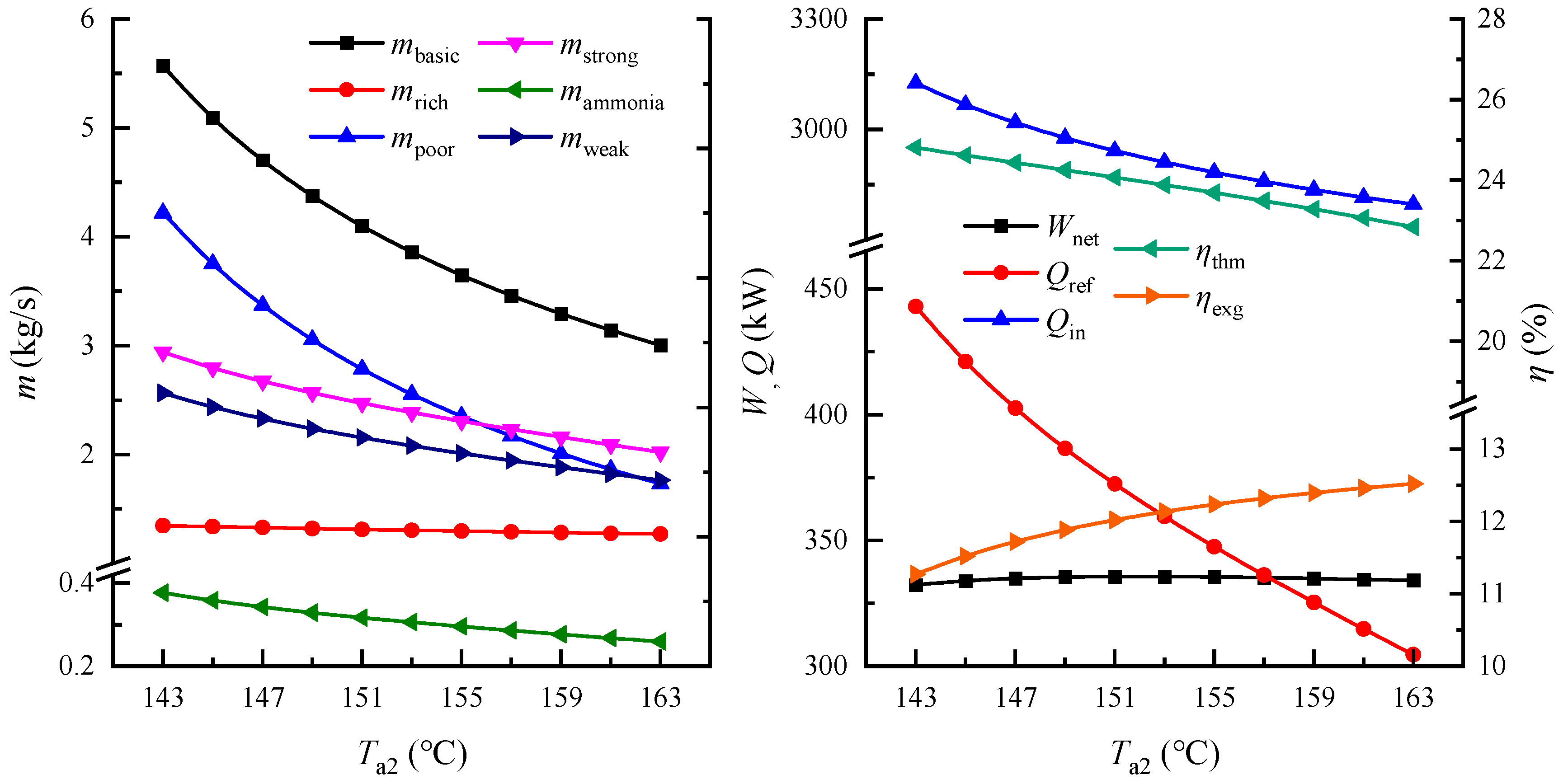
Figure 4 shows the effect of ammonia–water temperature at the vapor generator outlet on system performance. As the ammonia–water temperature at the vapor generator outlet increases, the mass flow rate of the ammonia–water basic solution which can be heated by the heat source decreases. Although the quality of ammonia–water basic solution entering the separator increases, the mass flow rate of ammonia-rich vapor generated in the separator is still reduced slightly (almost unchanged), and therefore the mass flow rate of the ammonia-poor solution must decrease. The turbine enthalpy drop is also almost constant, so the trend of power output of the turbine is the same as the ammonia-rich vapor mass flow rate, i.e., slightly decreasing but almost constant. The ammonia–water temperature at the vapor generator outlet has no effect on the pressure difference between the inlet and outlet pressures of pump-I and Ⅱ, but since the mass flow rates of the working fluids in the refrigeration cycle decrease as the mass flow rate of ammonia-poor solution decreases, the power consumption of pump-I and Ⅱ decreases, and hence the total power consumption of pumps is reduced. After calculation, the net output power of system shows a trend of increasing firstly and then decreasing in a small scale. Due to the mass flow rate of pure ammonia vapor in the refrigeration decreasing, the refrigeration output of the system also decreases. Because the mass flow rate of the ammonia–water basic solution in the top cycle is reduced, the amount of heat released by the heat source in the vapor generator is reduced, which means less energy is input to the system from the heat source. According to the formulas, it is calculated that the thermal efficiency of the system decreases, while the exergy efficiency increases.
(3) Rectification column pressure
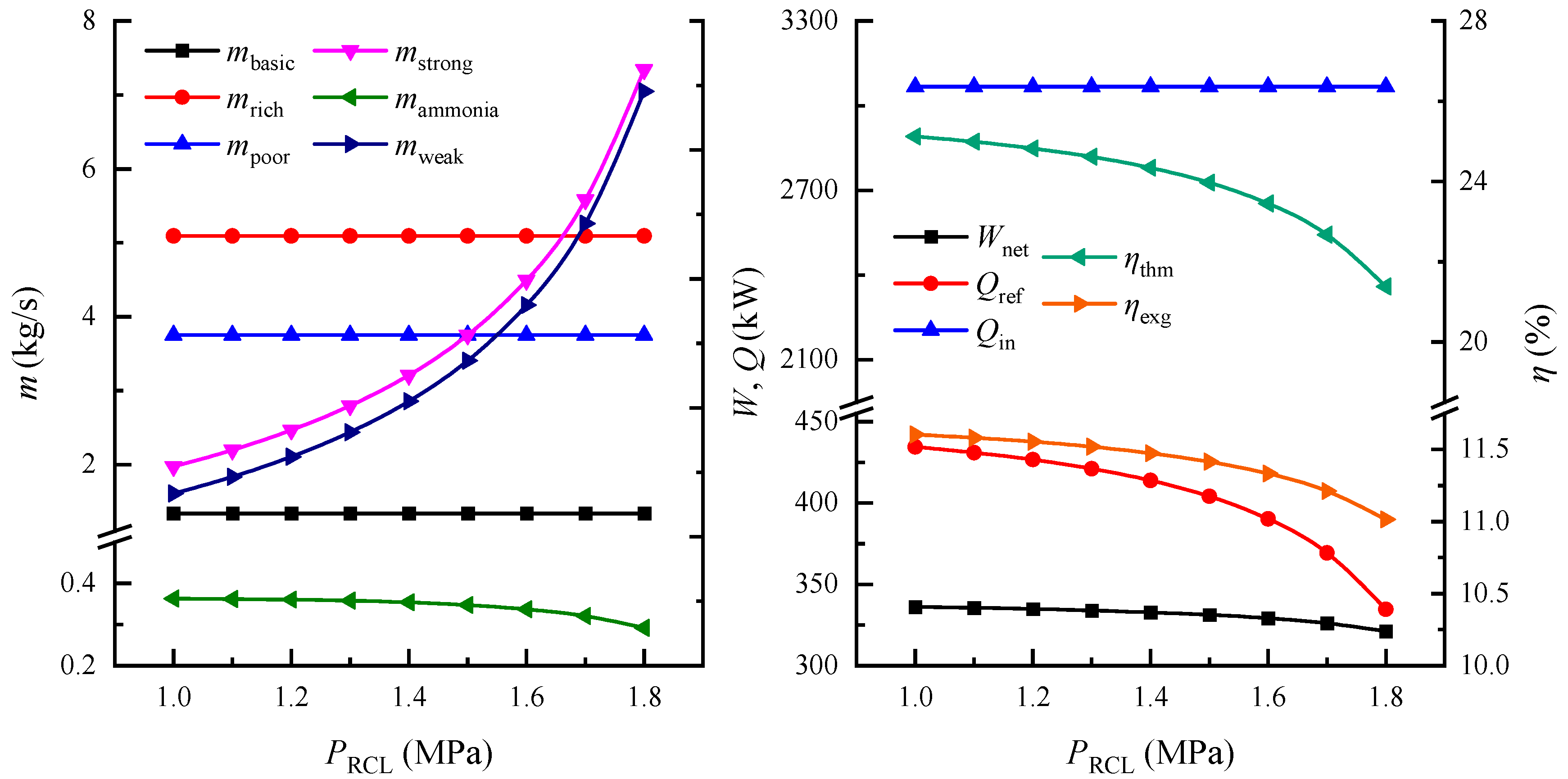
Figure 5 shows the effect of rectification column pressure on the system performance. The rectification column pressure is the parameter of the bottom cycle, which has no effect on the performance of top cycle, so each mass flow rate in the top cycle remains unchanged, and the power output of turbine and the power consumption of pump-I also remains unchanged. In the bottom cycle, with the increase of the rectification column pressure, the mass flow rate of ammonia-strong solution increases, but the mass flow rate of the pure ammonia vapor generated in the rectification column decreases slightly; thus, the mass flow rate of the discharged ammonia-weak solution increases. The pressure difference between the inlet and outlet of pump-Ⅱ increases with the increase of the rectification column pressure, so the power consumption of the pump-Ⅱ increases. After calculation, the net power output of the system decreases slightly. Due to the decreased mass flow rate of pure ammonia vapor, the refrigeration output of the system also decreases. In addition, the rectification column pressure has no effect on the parameters of the heat source in the power generation cycle, so the energy input to the system from the heat source remains constant. According to the formulas, it is obtained that both of the thermal efficiency and the exergy efficiency of system decrease with the increase of rectification column pressure.
(4) Evaporator pressure
Figure 6 shows the effect of evaporator pressure on system performance. The evaporator pressure has no effect on the performance of top cycle, which is similar to the rectification column pressure, so the power output of the turbine and the power consumption of pump-I remain constant. As the evaporator pressure increases, the pressure difference between the inlet and outlet of the pump-Ⅱ decreases, and its power consumption decreases. Therefore, the net power output of the system is calculated to increase slightly with increasing evaporator pressure. In addition, with the increase of the evaporator pressure, the phase-change evaporation heat absorption of pure ammonia per unit mass flow rate in evaporator increases, so the refrigeration output of the system increases. The energy input to the system from the heat source remains unchanged, and it is calculated that the thermal efficiency and the exergy efficiency of system are both increased slightly.
(5) Ammonia-weak solution temperature at the bottom outlet of the rectification column
Figure 7 shows the effect of the ammonia-weak solution temperature at the bottom outlet of the rectification column on the system performance. With the increase of the ammonia-weak solution temperature at the bottom outlet of rectification column, the ammonia-poor solution discharged from the separator of the top cycle releases less heat in the rectification column, which means that the heat absorbed by the bottom cycle decreases, so the mass flow rate of ammonia-strong solution in the bottom cycle declines, and the mass flow rate of pure ammonia vapor and ammonia-weak solution generated in the rectification column also decreases. In the top cycle, the power output of the turbine and the power consumption of pump-I remain constant, while in the bottom cycle, the power consumption of pump-Ⅱ decreases, leading to the net power output of system increasing slightly. The refrigeration output of the system also decreases with the reduction in the mass flow rate of the pure ammonia vapor in the bottom cycle. In the top cycle, since the ammonia-poor solution releases less heat in the rectification column, it releases more heat in the regenerator, which makes the temperature of the ammonia–water basic solution going back to the vapor generator increase, and therefore the heat source releases less heat in the vapor generator, i.e., the energy input to the system decreases. According to the formulas, it is calculated that the thermal efficiency of system decreases, while the exergy efficiency increases.

5. Conclusions

In this paper, a new combined cooling and power system based on ammonia–water working fluid is proposed. The system, coupled by the Kalina cycle and the ammonia–water absorption refrigeration cycle, is driven by a low-temperature heat source such as industrial waste gas. The steady-state mathematical model of the system is established in detail. According to the design condition results of the system, an exergy destruction distribution analysis is conducted for the system to explore the improvement potential of the system performance. Finally, a thermodynamic parametric analysis is performed to evaluate the effects of five key thermodynamic parameters on the system performance. The research conclusions obtained are as follows:
(1) In the proposed CCP system, the refrigeration cycle is driven by the waste heat of the power generation cycle, which conforms to the law of energy cascade utilization. Meanwhile, the system could avoid the corrosion of equipment or pipes caused by the low-temperature waste gas after use. The results of design conditions show that the thermal efficiency and exergy efficiency of the proposed system could reach 24.62% and 11.52%, respectively.
(2) The results of exergy destruction analysis for the proposed system reveal that the major exergy destructions occur in the heat exchangers, including vapor generator, condenser, regenerator and absorber, which are mainly on account of the large mass flow rate of fluid and average heat transfer temperature difference. Additionally, the exergy destruction of the turbine also occupies a large part of the total amounts, which can be improved by using the turbine with higher isentropic efficiency.
(3) The thermodynamic parameter analysis shows that within a certain range, increasing turbine inlet pressure and evaporator pressure can improve the thermal efficiency of the system, but increasing rectification column pressure, ammonia–water temperature at vapor generator outlet and ammonia-weak solution temperature at the bottom outlet of the rectification column will reduce the thermal efficiency of the system. When the cooling capacity is converted into cooling exergy, the value will be greatly reduced, so the change trend of exergy efficiency and thermal efficiency may not be consistent. There is an optimal turbine inlet pressure that makes the exergy efficiency of the system maximal. Increasing ammonia–water temperature at vapor generator outlet and ammonia-weak solution temperature at the bottom outlet of the rectification column will increase the exergy efficiency of the system obviously, whereas the rectification column pressure and evaporator pressure only have a negligible effect on the exergy efficiency of the system.

Author Contributions

Conceptualization, H.W. and J.W.; Investigation, H.W. and Z.L.; Supervision, J.W. and H.C.; Writing—original draft, H.W.; Writing—review & editing, J.W. and X.L. All authors have read and agreed to the published version of the manuscript.

Funding

This research was funded by National Natural Science Foundation of China (Grant No. 51906131), China Postdoctoral Science Foundation (Grant No. 2020M673604XB) and Science and Technology Planning Project of Yulin City (Grant No. CXY-2020-089).

Institutional Review Board Statement

Not applicable.

Informed Consent Statement

Not applicable.

Data Availability Statement

Most data are included in the manuscript.

Conflicts of Interest

The authors declare no conflict of interest.

Nomenclature

exg: exergy
e: Specific exergy(kW·kg−1)g: waste gas
h: Specific enthalpy (kJ·kg−1)in: input
m: Mass flux (kg·s−1)net: net value
P: Pressure (kPa)p-I: pump-I
Q: Quantity of heat flow (kW)p-Ⅱ: pump-Ⅱ
s: Specific entropy (kJ· kg−1 K−1)poor: ammonia-poor solution
T: Temperature (°C)RCL: rectification column
W: Power input/output (kW)ref: refrigeration
X: Ammonia concentration (%)rich: ammonia-rich vapor
Greek symbols: isentropic
η: Efficiencystrong: ammonia-strong solution
Subscripttb: turbine
ammo: pure ammoniathm: thermal
basic: ammonia–water basic solutionweak: ammonia-weak solution
c: cooling water0: environmental state
EVP: evaporationg1-g3,a1-a12,b1-b12,c1-c6,d1-d2: state point

References

  1. Du, Y.; Han, P.; Qiang, X.; Hao, M.; Long, Y.; Zhao, P.; Dai, Y. Off-design performance analysis of a combined cooling and power system driven by low-grade heat source. Energy Convers. Manag. 2018, 159, 327–341. [Google Scholar] [CrossRef]
  2. Wang, J.; Wang, J.; Zhao, P.; Dai, Y. Thermodynamic analysis of a new combined cooling and power system using ammonia–water mixture. Energy Convers. Manag. 2016, 117, 335–342. [Google Scholar] [CrossRef]
  3. Cao, L.; Wang, J.; Chen, L.; Lou, J.; Wang, J.; Dai, Y. Thermoeconomic Analysis and Multi-Objective Optimization of a Combined Cooling and Power System Using Ammonia-Water Mixture: Case Study. J. Energy Eng. 2018, 144, 05018001. [Google Scholar] [CrossRef]
  4. Hua, J.; Chen, Y.; Wang, Y.; Roskilly, A.P. Thermodynamic analysis of ammonia–water power/chilling cogeneration cycle with low-grade waste heat. Appl. Therm. Eng. 2014, 64, 483–490. [Google Scholar] [CrossRef]
  5. Zhang, S.; Chen, Y.; Wu, J.; Zhu, Z. Thermodynamic analysis on a modified Kalina cycle with parallel cogeneration of power and refrigeration. Energy Convers. Manag. 2018, 163, 1–12. [Google Scholar] [CrossRef]
  6. Shankar, R.; Srinivas, T. Coupled cycle with Kalina cycle system and vapor absorption refrigeration. Proc. Inst. Mech. Eng. Part A J. Power Energy 2014, 228, 953–964. [Google Scholar] [CrossRef]
  7. Shankar, R.; Srinivas, T. Performance investigation of Kalina cooling cogeneration cycles. Int. J. Refrig. 2018, 86, 163–185. [Google Scholar] [CrossRef]
  8. Shankar, R.; Rivera, W. Investigation of new cooling cogeneration cycle using NH3H2O mixture. Int. J. Refrig. 2020, 114, 88–97. [Google Scholar] [CrossRef]
  9. Qu, W.; Hong, H.; Su, B.; Tang, S.; Jin, H. A concentrating photovoltaic/Kalina cycle coupled with absorption chiller. Appl. Energy 2018, 224, 481–493. [Google Scholar] [CrossRef]
  10. Cao, L.; Lou, J.; Wang, J.; Dai, Y. Exergy analysis and optimization of a combined cooling and power system driven by geothermal energy for ice-making and hydrogen production. Energy Convers. Manag. 2018, 174, 886–896. [Google Scholar] [CrossRef]
  11. Feng, C.; Yu, Z.; Liang, W.; Wang, D. Energetic, exergetic and economic analysis and multi-objective optimization of two novel ammonia-water absorption combined power and cooling cycles driven by low-grade heat sources. Energy Convers. Manag. 2021, 248, 114781. [Google Scholar] [CrossRef]
  12. Rashidi, J.; Ifaei, P.; Esfahani, I.J.; Ataei, A.; Yoo, C.K. Thermodynamic and economic studies of two new high efficient power-cooling cogeneration systems based on Kalina and absorption refrigeration cycles. Energy Convers. Manag. 2016, 127, 170–186. [Google Scholar] [CrossRef]
  13. Higa, M.; Yamamoto, E.Y.; Oliveira, J.C.D.d.; Conceição, W.A.S. Evaluation of the integration of an ammonia-water power cycle in an absorption refrigeration system of an industrial plant. Energy Convers. Manag. 2018, 178, 265–276. [Google Scholar] [CrossRef]
  14. Nedaei, N.; Hamrang, F.; Farshi, L.G. Design and 3E analysis of a hybrid power plant integrated with a single-effect absorption chiller driven by a heliostat field: A case study for Doha, Qatar. Energy 2022, 239, 122415. [Google Scholar] [CrossRef]
  15. Cao, L.; Wang, J.; Wang, H.; Zhao, P.; Dai, Y. Thermodynamic analysis of a Kalina-based combined cooling and power cycle driven by low-grade heat source. Appl. Therm. Eng. 2017, 111, 8–19. [Google Scholar] [CrossRef]
  16. Kim, K.H. Thermodynamic Analysis of Kalina Based Power and Cooling Cogeneration Cycle Employed Once Through Configuration. Energies 2019, 12, 1536. [Google Scholar] [CrossRef] [Green Version]
  17. Dhahad, H.A.; Hussen, H.M.; Nguyen, P.T.; Ghaebi, H.; Ashraf, M.A. Thermodynamic and thermoeconomic analysis of innovative integration of Kalina and absorption refrigeration cycles for simultaneously cooling and power generation. Energy Convers. Manag. 2020, 203, 112241. [Google Scholar] [CrossRef]
  18. Abam, F.I.; Briggs, T.A.; Diemuodeke, O.E.; Ekwe, E.B.; Ujoatuonu, K.N.; Isaac, J.; Ndukwu, M.C. Thermodynamic and economic analysis of a Kalina system with integrated lithium-bromide-absorption cycle for power and cooling production. Energy Rep. 2020, 6, 1992–2005. [Google Scholar] [CrossRef]
  19. Ouyang, T.; Wang, Z.; Wang, G.; Zhao, Z.; Xie, S.; Li, X. Advanced thermo-economic scheme and multi-objective optimization for exploiting the waste heat potentiality of marine natural gas engine. Energy 2021, 236, 121440. [Google Scholar] [CrossRef]
  20. Yadav, S.K.; Singh, O. Parametric study of solid oxide fuel cell based novel power and desalination system. Energy Sources Part A Recovery Util. Environ. Eff. 2022, 44, 3785–3802. [Google Scholar] [CrossRef]
  21. Almatrafi, E.; Khaliq, A.; Alquthami, T. Thermodynamic investigation of a novel cooling-power cogeneration system driven by solar energy. Int. J. Refrig. 2022, 138, 244–258. [Google Scholar] [CrossRef]
  22. Yu, Z.; Han, J.; Liu, H.; Zhao, H. Theoretical study on a novel ammonia–water cogeneration system with adjustable cooling to power ratios. Appl. Energy 2014, 122, 53–61. [Google Scholar] [CrossRef]
  23. Kumar, G.P.; Saravanan, R.; Coronas, A. Experimental studies on combined cooling and power system driven by low-grade heat sources. Energy 2017, 128, 801–812. [Google Scholar] [CrossRef]
  24. Mahmoudi, S.M.S.; Kordlar, M.A. A new flexible geothermal based cogeneration system producing power and refrigeration. Renew. Energy 2018, 123, 499–512. [Google Scholar] [CrossRef]
  25. Kordlar, M.A.; Mahmoudi, S.M.S.; Talati, F.; Yari, M.; Mosaffa, A.H. A new flexible geothermal based cogeneration system producing power and refrigeration, part two: The influence of ambient temperature. Renew. Energy 2019, 134, 875–887. [Google Scholar] [CrossRef]
  26. Pacheco-Reyes, A.; Rivera, W. Thermodynamic cycles for the simultaneous production of power and cooling: A comprehensive review. Int. J. Energy Res. 2021, 45, 12500–12535. [Google Scholar] [CrossRef]
  27. Jing, X.; Zheng, D. Effect of cycle coupling-configuration on energy cascade utilization for a new power and cooling cogeneration cycle. Energy Convers. Manag. 2014, 78, 58–64. [Google Scholar] [CrossRef]
  28. Shokati, N.; Ranjbar, F.; Yari, M. A comprehensive exergoeconomic analysis of absorption power and cooling cogeneration cycles based on Kalina, part 1: Simulation. Energy Convers. Manag. 2018, 158, 437–459. [Google Scholar] [CrossRef]
  29. Shokati, N.; Ranjbar, F.; Yari, M. A comprehensive exergoeconomic analysis of absorption power and cooling cogeneration cycles based on Kalina, Part 2: Parametric study and optimization. Energy Convers. Manag. 2018, 161, 74–103. [Google Scholar] [CrossRef]
  30. Patil, R.S.; Bhagwat, S.S. Thermodynamic analysis and optimisation of double effect absorption type combined power and cooling cycle using LiBr-water as working fluid. Int. J. Exergy 2021, 34, 159–178. [Google Scholar] [CrossRef]
  31. Kalan, A.S.; Ghiasirad, H.; Saray, R.K.; Mirmasoumi, S. Thermo-economic evaluation and multi-objective optimization of a waste heat driven combined cooling and power system based on a modified Kalina cycle. Energy Convers. Manag. 2021, 247, 114723. [Google Scholar] [CrossRef]
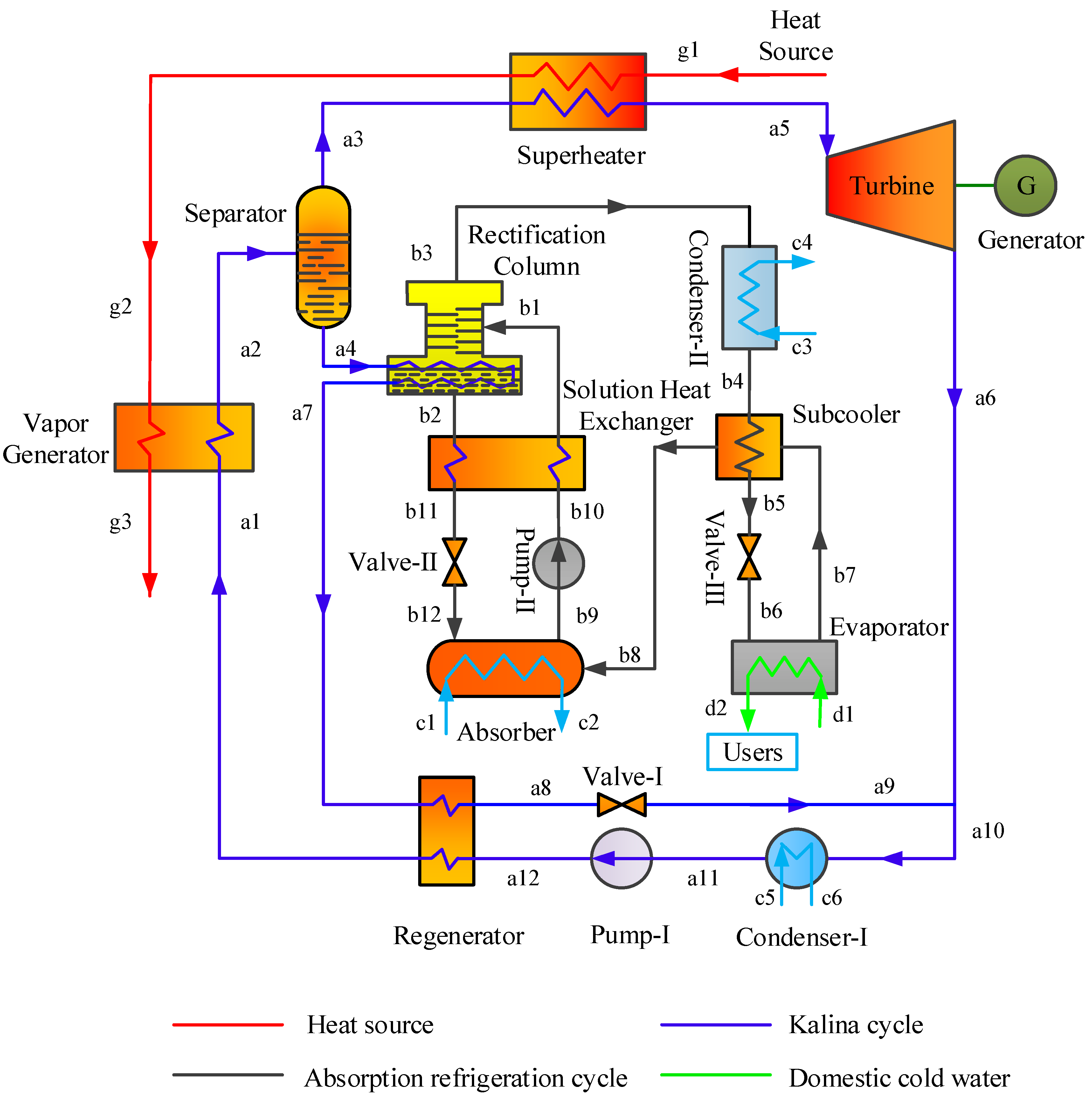
Figure 1. A schematic diagram of a new combined cooling and power system based on ammonia–water working fluid.
Sustainability 14 13260 g001
Figure 2. Exergy destruction distribution in the system.
Sustainability 14 13260 g002
Figure 3. Influence of the turbine inlet pressure on system performance.
Sustainability 14 13260 g003
Figure 4. Influence of ammonia–water temperature at the vapor generator outlet on system performance.
Sustainability 14 13260 g004
Figure 5. Influence of the rectification column pressure on system performance.
Sustainability 14 13260 g005
Figure 6. Influence of the evaporation pressure on system performance.
Sustainability 14 13260 g006
Figure 7. Influence of the ammonia-weak solution temperature at the bottom outlet of the rectification column on system performance.
Sustainability 14 13260 g007
Table 1. Exergy models for each component of the CCP system.
ComponentExergy Equation (kW)
Vapor generatorIvg = Eg2Eg3 + Ea1Ea2
SeparatorIsep = Ea2Ea3Ea4
SuperheaterIsup = Eg1Eg2 + Ea3Ea5
TurbineItb = Ea5Ea6Wtb
RegeneratorIreg = Ea12-Ea1 + Ea7-Ea8
Rectification columnIrcl = Ea4Ea7 + Eb1Eb2Eb3
AbsorberIabs = Eb8 + Eb12Eb9 + Ec1Ec2
Solution heat exchangerIshe = Eb2Eb11 + Eb10Eb1
SubcoolerIsub = Eb4Eb5 + Eb7Eb8
EvaporatorIevp = Eb6Eb7 + Ed1Ed2
Condenser-IIcnd-I = Ea10Ea11 + Ec5Ec6
Condenser-ⅡIcnd-Ⅱ = Eb3Eb4 + Ec3Ec4
Pump-IIp-I = Ea11Ea12
Pump-ⅡIp-I = Eb9-Eb10 + Wp-Ⅱ
Valve-IIv-I = Ea8Ea9
Valve-ⅡIv-Ⅱ = Eb11Eb12
Valve-ⅢIv-Ⅲ = Eb5Eb6
Table 2. The initial setting parameters of the CCP system.
Initial ParametersValue
Ambient temperature Tamb/°C20
Ambient pressure Pamb/kPa101.3
Heat source temperature Tg/°C200
Heat source pressure Pg/kPa140
Mass flow rate of heat source mg/kg·s−130
Cold refrigerant water temperature mc/°C5
Ammonia mass fraction of basic solution Xbasic/%60
Ammonia mass fraction of ammonia-strong solution Xstrong/%40
Turbine isentropic efficiency ηtb/%80
Pump isentropic efficiency ηp/%70
Turbine inlet pressure Pa5/kPa5000
Turbine outlet pressure Pa6/kPa600
Heat exchanger minimum terminal temperature difference ∆Tmin/°C5
Table 3. The thermodynamic parameters of each state point of the system under design conditions.
Working FluidStateT/°CP/kPah/
kJ·kg−1
s/
kJ·kg−1·K−1
QualityX/%m/
kg·s−1
waste gasg1200.00 140 475.84 7.24 //30.00
waste gasg2193.56 140 469.24 7.22 //30.00
waste gasg399.56 140 373.60 6.99 //30.00
ammonia–water basic solutiona184.95 5000 386.06 1.95 060.00 5.09
ammonia–water basic solutiona2145.00 5000 949.57 3.38 0.2660.00 5.09
ammonia-rich vapora3145.00 5000 1857.83 5.75 193.49 1.34
ammonia-poor solutiona4145.00 5000 625.61 2.53 048.05 3.75
ammonia-rich vapora5190.00 5000 2005.63 6.09 193.49 1.34
ammonia-rich vapora672.19 600 1722.79 6.29 0.9593.49 1.34
ammonia-poor solutiona7115.00 5000 466.57 2.13 048.05 3.75
ammonia-poor solutiona841.03 5000 93.53 1.07 048.05 3.75
ammonia-poor solutiona941.66 600 93.53 1.08 0.2560.00 3.75
ammonia–water basic solutiona1047.38 600 521.87 2.46 060.00 5.09
ammonia–water basic solutiona1130.11 600 103.14 1.11 060.00 5.09
ammonia–water basic solutiona1231.03 5000 111.10 1.12 048.05 5.09
ammonia-strong solutionb191.85 1300 340.30 1.76 0.0240.00 2.80
ammonia-weak solutionb2110.00 1300 395.27 1.83 031.19 2.44
pure ammoniab333.68 1300 1632.74 5.70 1100.00 0.36
pure ammoniab433.68 1300 503.98 2.02 0100.00 0.36
pure ammoniab518.12 1300 429.52 1.77 0100.00 0.36
pure ammoniab6−1.88 400 429.52 1.79 0.07100.00 0.36
pure ammoniab7−1.88 400 1605.15 6.12 1100.00 0.36
pure ammoniab828.68 400 1679.60 6.38 1100.00 0.36
ammonia-strong solutionb946.39 400 91.44 1.04 040.00 2.80
ammonia-strong solutionb1046.56 1300 92.93 1.05 040.00 2.80
ammonia-weak solutionb1151.56 1300 111.56 1.03 031.19 2.44
ammonia-weak solutionb1251.69 400 111.56 1.03 031.19 2.44
cooling waterc120.00 101.3 84.01 0.30 //18.47
cooling waterc228.00 101.3 117.46 0.41 //18.47
cooling waterc320.00 101.3 84.01 0.30 //12.08
cooling waterc428.00 101.3 117.46 0.41 //12.08
cooling waterc520.00 101.3 84.01 0.30 //63.73
cooling waterc628.00 101.3 117.46 0.41 //63.73
refrigerant waterd120.00 101.3 84.01 0.30 //6.70
refrigerant waterd25.00 101.321.12 0.08 //6.70
Table 4. Performance parameters of the system under design conditions.
TermValueUnit
Power output of turbine378.65kW
Power consumption of pump44.70kW
Net power output of the system333.94kW
Refrigeration output421.07kW
System energy input3067.24kW
Refrigeration exergy 11.16kW
System exergy input2996.05kW
Thermal efficiency24.62%
Exergy efficiency11.52%
Publisher’s Note: MDPI stays neutral with regard to jurisdictional claims in published maps and institutional affiliations.