Article

An Engine Exhaust Utilization System by Combining CO2 Brayton Cycle and Transcritical Organic Rankine Cycle

College of Electromechanical Engineering, Qingdao University of Science and Technology, Qingdao 266061, China
*
Author to whom correspondence should be addressed.
Sustainability 2022, 14(3), 1276; https://doi.org/10.3390/su14031276
Submission received: 23 December 2021 / Revised: 14 January 2022 / Accepted: 18 January 2022 / Published: 24 January 2022
(This article belongs to the Special Issue Sustainable Research of Power Cycles for Energy Conversion)

Abstract

:
For engine exhaust gas heat recovery, the organic Rankine cycle (ORC) cannot be directly used due to the thermal stability and safety of organic fluids. Thus, a creative power system is given by integrating the supercritical CO2 Brayton cycle and transcritical ORC. This system can directly utilize the thermal energy of a high-temperature exhaust gas. The inefficiencies in the heat exchangers are highly reduced by using supercritical working fluid. The mathematical model of the system, covering both the thermodynamic and economic aspects, is built in detail. It is found that the highest irreversible loss takes place in the gas heater, taking 21.14% of the total exergy destruction. The ORC turbine and CO2 turbine have the priority for improvement, compared to the compressor and pump. The increase in CO2 turbine inlet pressure improves the system exergy efficiency and levelized cost of energy. Both the larger CO2 and ORC turbine inlet temperatures contribute to a decrease in levelized cost of energy and a rise in system exergy efficiency. There is a maximum value of system exergy efficiency and minimum value of levelized cost of energy by varying the ORC turbine inlet pressure. The determined exergy efficiency and levelized cost of energy in the proposed system are 54.63% and 36.95 USD/MWh after multi-objective optimization.

1. Introduction

The requirement for energy has experienced a substantial rise in the past few decades around the world, especially in developing nations that are expediting urbanization advancement. The report indicates that the energy consumption by China in 2050 could be more than 15 times of that in 1970 [1]. The carbon-based conventional fossil fuels still contribute the most in global energy supply, and research demonstrates that fossil fuels produce 70% of the world power generations [2]. The fast depletion of conventional fossil fuels has inevitably caused significant energy and environmental issues such as energy shortages and environment pollution. To address these problems, one important pathway is to substitute renewable energy such as solar and wind for conventional fossil fuels to change the current energy structure. On the other hand, effective utilization of waste heat is also a critical measure to improve overall energy efficiency. For instance, the internal combustion engine is a motive power source in many energy fields, while the capacity of the thermal energy carried by exhaust gas and cooling water can use almost 50 percentage of the total fuel energy [3].
To recover the waste heat of engine, one can review that the organic Rankine cycle (ORC), which has reaped a lot of attention, owing to its advantages of simple structure, flexibility, and desirable efficiency [4]. Organic fluid selection is the first important procedure in designing an efficient ORC for recovering engine waste heat. Tian et al. [5] reported an impressive work in respect to the thermal characteristics of an ORC along with its economic performance. This ORC was powered by the exhaust thermal gas of an internal combustion engine, separately working with 20 organic fluids; their research results suggested R141b, R123 and R245fa might be the first selection candidates. To find the prospective substance that can effectively service the engine waste heat ORC with solid physics, Su et al. [6] proposed a theoretical thermal efficiency model through strict mathematical derivation, which was convenient in performance prediction. Yang and Yeh [7] examined the applicability of several organic fluids, i.e., R245fa, R600a, R600, and R1234ze, in the given ORC that was applied to utilize the heat of exhaust gas discharged from a heavy marine engine, and they highly praised the R245fa to be the leading working fluid in the examined case. Configuration optimization is also an effective approach in improving the efficiency of the ORC system, such as adding preheater and recuperator to the conventional ORC [8,9]. More recently, the cascade utilization principle has been pursued in utilizing the engine waste heat by employing an ORC system in the dual loop manner. In general, one loop in a high temperature was powered by the exhaust heat while another loop in a low temperature was driven by the residual heat of exhausted heat [10], high-temperature loop [11], and jacket water [12].
However, there is always a minimal temperature difference existing inside the ORC evaporator because of an isothermal evaporation process on the working fluid. This temperature difference, called the pinch point, restrains strictly the thermal energy transportation from heat source to ORC system. Therefore, the transcritical ORC could produce a preferable temperature match and highly enhance the exergy efficiency in the heating process [13]. Yang et al. [14] suggested reclaiming the discharged heat of a marine diesel engine through arranging a simple transcritical ORC rounded with R1234yf. A total of three operating models could be identified based on the input heat source, using the different combinations of cylinder cooling water, exhaust gas, and scavenge air cooling water. A comparison between subcritical ORC and transcritical ORC was conducted by using the working medium of R245fa and the heat source of biogas fueled by engine exhaust heat [15]. Wang et al. [16] proposed an integrated dual loop transcritical-subcritical ORC power system to efficiently recover the thermal energy from both the coolant as well as the engine exhaust gas. The high-temperature transcritical subloop was operated with R1233zd as the working fluid and exhaust gas waste heat as the prime mover, while the low-temperature subcritical loop working with R1234yf absorbed the residual heat of the transcritical loop, coolant heat, and residual heat of the exhaust gas in sequence.
It can be emphasized that many instructive attempts have been made on the discussion of the engine waste heat utilization by employing ORC technology. Nevertheless, there is still a large gap on effectively recycling the waste heat of engine exhaust gas. It is reported that essentially the engine exhaust gas possesses a temperature above 450 °C [17]. Regretfully, most of the refrigerants are provided with a decomposition temperature of about 200~300 °C [18,19]. The thermal stability and safety of organic fluids highly restrains the power generation temperature of ORC, and there are large irreversible losses in the heat transfer action from exhaust gas to working fluid. This motivates researchers to seek high-temperature thermal power cycles to substitute for or coupled with ORC. The transcritical CO2 Rankine cycle has thus drawn much attention in the engine waste heat recovery field for its eco-friendliness, small system footprint, and lack of fire hazard [20,21]. One of the main issues that this type of power cycle faces is how to effectively condense the subcritical CO2 with ambient cooling sources in consideration of the low critical temperature (31 °C), especially for engine waste heat recovery. The cascade power systems, by integrating steam Rankine cycle as the top loop with ORC as the bottom loop, have been explored to improve the system’s overall efficiency [22]. A significant limitation for the steam Rankine cycle is its large bulk of components when it is used with engines [23].
It is underlined that the system miniaturization is a strict requirement for the waste heat recovery cycle of engines. The working fluid in its supercritical state is provided with favorable heat transfer performance and high density, which enables the compact designs of turbo-machinery and the heat exchanger. Considering the characteristics of CO2 and organic substances, the integrated system, combing supercritical CO2 Brayton cycle and transcritical ORC, may be an interesting solution to recycle engine waste heat for its compact configuration, stability, and high thermal efficiency. To the best of our best knowledge, the applicability of this integrated system for engines is not explicit and not much relevant investigation exists. In the newly proposed power system, the CO2 Brayton cycle acts as the top loop to directly utilize the high-temperature engine exhaust heat due to the excellent thermal stability and inert nature of CO2. The transcritical ORC is arranged as the bottom loop driven by the turbine exhaust of the CO2 Brayton cycle. Thermodynamic and economic examination is performed to assess the evolution of the system performance versus critical variables. Several screened organic substances are further quantitatively studied to determine the suitable candidate for cycling the system. Moreover, the system optimizations are completed through the method of genetic algorithm to achieve the optimal operating conditions by trade-off of the levelized cost of energy and system exergy efficiency.

2. Cycle Structure

Figure 1 expresses the structure of the integrated thermal power system for recovering the waste heat of the engine exhaust. It can be observed that the system comprises of a CO2 Brayton cycle and transcritical ORC in a cascade arrangement. The high-temperature exhaust gas from an engine (state 14) is introduced into the gas heater to motivate the CO2 Brayton cycle. The high-pressure supercritical CO2 (state 3) absorbs the heat in the gas heater to arrive at a high temperature. Subsequently, the high-grade CO2 (state 4) expands over the CO2 turbine to give rise to power. The exhaust by CO2 turbine (state 5) is delivered to the internal heat exchanger (IHE) to drive the transcritical ORC. A CO2 regenerator is also arranged after the IHE to recycle the waste heat of CO2. Afterwards, the supercritical CO2 (state 7) is cooled down to the compressor inlet temperature.
In the transcritical ORC, the organic liquid in subcritical pressure (state 8) is pumped to the supercritical pressure (state 9). Then the high-pressure organic liquid is heated in the ORC regenerator and IHE in sequence to supercritical state (state 11). The supercritical organic fluid enters ORC turbine for producing power. The organic gas is finally chilled to saturated liquid when it flows through the condenser. The organic substance R290 is identified to be the working fluid for transcritical ORC due mainly to the favorable thermophysical action, high stability, and environmental-friendliness [24,25].

3. Mathematical Model

The thermoeconomic models of the system are introduced in this section. Several assumptions are illustrated to simplify the system simulation: (1) pressure drops and heat rejections are ignored in connecting pipes and heat exchangers; (2) the system is in a stable state; (3) there is saturated liquid at the exit of condenser; and (4) the potential and kinetic energies are invariable.

3.1. Thermodynamic Analysis

Energy balance equations for each system component can be achieved by applying the theory of first thermodynamic law. The components of the proposed system can be categorized into turbo-machinery and heat exchanger.
For CO2 and ORC turbines, the produced power can be W ˙ calculated as:
{ W ˙ T C O 2 = m ˙ C O 2 ( h 4 h 5 ) W ˙ T O R C = m ˙ O R C ( h 11 h 12 )
where m ˙ and h stand for mass flow rate and enthalpy, respectively. The unknown enthalpy of the turbine exit can be computed by introducing the component isentropic efficiency:
η T = ( h e n h e x ) ( h e n h e x , i s )
in which subscripts en and ex mean the entrance and exit of examined component, and is indicates the isentropic process.
For compressor and pump, the consumed power is given by:
{ W ˙ C = m ˙ C O 2 ( h 2 h 1 ) W ˙ P = m ˙ O R C ( h 9 h 8 )
The isentropic efficiency of compressor and pump is:
η C , P = ( h e x , i s h e n ) ( h e x h e n )
For heat exchangers, the energy balance equation can be written as:
{ m ˙ C O 2 ( h 4 h 3 ) = m ˙ g a s ( h 14 h 15 ) m ˙ C O 2 ( h 3 h 2 ) = m ˙ C O 2 ( h 6 h 7 ) m ˙ C O 2 ( h 7 h 1 ) = m ˙ 16 ( h 17 h 16 ) m ˙ C O 2 ( h 5 h 6 ) = m ˙ O R C ( h 11 h 10 ) m ˙ O R C ( h 10 h 9 ) = m ˙ O R C ( h 12 h 13 ) m ˙ O R C ( h 13 h 8 ) = m ˙ 18 ( h 19 h 18 )
As a significant supplement to energy analysis, exergy analysis is performed by aid of the second thermodynamic law. Definition of the exergy flow rate at a steady point j is given by [26]:
E ˙ j = m ˙ j [ ( h j h 0 ) T 0 ( s j s 0 ) ]
in which T and s are separately expressed as temperature and entropy. Subscript 0 means a dead state that is taken as ambient condition.
The exergy balance equation for each component can be expressed as [27]:
E ˙ D = E ˙ F E ˙ P
where E ˙ D , E ˙ F and E ˙ P denote the exergy destruction, fuel exergy, and product exergy in sequence.
Table 1 presents the specific exergies of components.
The power output by the proposed power system is:
W ˙ n e t = W ˙ T C O 2 W ˙ C + W ˙ O R C W ˙ P
The system thermal efficiency is given by:
η t h = W ˙ n e t m ˙ g a s ( h 14 h 15 )
The exergy efficiency of the system is expressed as:
η e x e = W ˙ n e t m ˙ g a s [ h 14 h ( p 14 , T 0 ) T 0 ( s 14 s ( p 14 , T 0 ) ) ]

3.2. Heat Transfer Area

Detailed models are presented to the heat transfer process because the heat transfer area is usually the sizing factor in calculating the investment cost of equipment. All heat transfer units of the proposed cycle are the shell-and-tube type of heat exchanger. The heat exchangers must be discretized into many small sections with equal enthalpy interval owning to the large variations of thermophysical properties versus narrow temperature change for supercritical and condensing fluids [28]. The heat transfer area of each segment is calculated by:
A i = Q ˙ i U i Δ T i
where Qi and ΔTi are the heat transfer rate and average temperature difference in the ith section, respectively, and coefficient of heat transfer Ui is expressed as [29]:
U i = 1 1 α t , i d t , o d t , i n + 1 α s , i
To the heat transfer with fluid in single phase, αt is written as:
α t = λ f N u d e
and αs is [30]:
α s = 0.36 λ f d e ( ρ u e d e μ ) 0.55 P r 1 / 3 ( μ μ w ) 0.14
Here, λf is the coefficient of thermal conductivity, ρ is density, μ is dynamic viscosity, and Pr is Prandtl number. The characteristic diameter de is taken as inner diameter of tube in the tube side and is calculated by below equation for shell side:
d e , s = 1.10 P t 2 d t , o d t , o
where Pt is the centerline spacing between tubes.
The Nusselt number Nu in the tube side is expressed with below equation [28]:
N u = { 4.089 ( R e < 2300 ) 4.089 + N u 5000 4.089 5000 2300 ( R e 2300 ) ( 2300 R e < 5000 ) ( f d / 8 ) ( R e 1000 ) P r 1 + 12.7 ( P r 2 / 3 1 ) f d / 8 ( R e 5000 )
where Re is the Reynolds number and fd is friction factor.
For the phase change behavior of working fluid, the Cavallini correlation [29] is applied:
α t = 0.05 R e e 0.8 P r s a t , l i q 0.33 λ l i q d t , i n
Here, the Ree is the equivalent value of Reynolds number, which is the function of Reynolds number of saturated liquid and saturated vapor (Reliq and Revap). They are expressed as below:
R e e = R e v a p μ s a t , v a p μ s a t , l i q ( ρ s a t , l i q ρ s a t , v a p ) 0.5 + R e l i q
R e l i q = m ˙ f A f ( 1 x ) d t , i n μ s a t , l i q
R e v a p = m ˙ f A f x d t , i n μ s a t , v a p
in which x is the quality fraction of saturated vapor.
The heat exchanger area can be calculated according to the mathematical models introduced above and then the achieved value is served as the size to calculate the cost of heat exchangers in following economical evaluation.

3.3. Economic Analysis

The cost function equation in Ref. [31] is used to compute the investment cost of components, which is expressed as:
Z = y 1 X z + y 2
For compressor, turbine and pump, the sizing factor X is power and it is heat transfer area for heat exchanger. The relevant parameter about Equation (21) is listed in Table 2.
These cost values are obtained by interpolating data from selected vendors during the year 2009. Due to the absence of detailed cost data, each equipment cost is estimated as a function of a single sizing factor. For turbomachinery, only the shaft power is used for cost accounting. For heat exchangers, the sizing factor is the heat exchanger area. Moreover, the total capital cost includes the overall investment of typical components and the balance of the system (20% of total capital cost [30]) that is the cost of pipes, valves, and control system.
It is known that the apparatus cost of equipment is affected by time, owing to the inflation of social economics. Therefore, the investment cost estimated by using functions in Table 2 must be converted to a value at the reference year, which is 2018 in the study. With the aid of Chemical Engineering Plant Cost Index (CI), the equipment cost required is:
Z r e f = Z o r i g × C I r e f C I o r i g
The overall annual cost of system is determined by calculating the levelized total initial cost and the operation and maintenance fees:
Z ˙ t o t = Z ˙ t o t , C I + Z ˙ t o t , O M
Z ˙ t o t , C I = ( C R F N × 3600 ) Z t o t
Z ˙ t o t , O M = γ Z t o t N × 3600
where γ is the factor associated with the operation and maintenance cost and N is the operation hours in one year, the values of which are 1.5% [21] and 8000 [28] in the study.
The capital recovery factor CRF is written as:
C R F = i r ( 1 + i r ) n ( 1 + i r ) n 1
in which the economic life n is taken as 30 years and interest rate ir is 5%.
Finally, the levelized cost of energy (LCOE) by the proposed system is calculated by:
L C O E = Z ˙ t o t W ˙ n e t

4. Results and Discussion

The newly proposed power system is assessed by using an in-house program opened by authors in the MATLAB platform, combined with the database REFPROP [32]. The thermophysical conditions of the engine exhaust gas reported in Ref. [33] is fetched as the waste heat source. The input variables to simulate the power system are specified in Table 3.

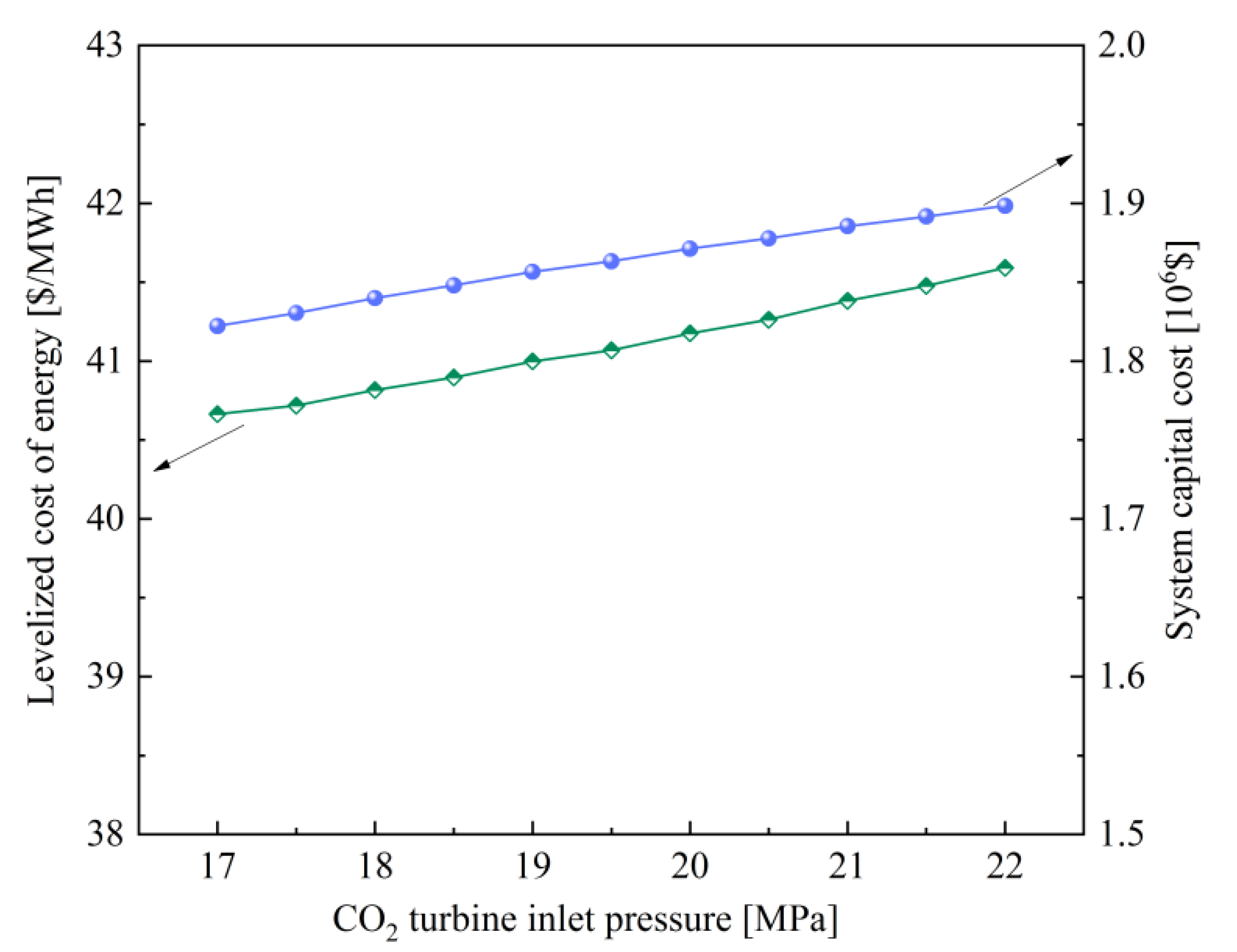
4.1. Effect of CO2 Turbine Inlet Pressure pCO2T,in

The pressure pCO2T,in in the CO2 Brayton cycle is examined in this section, as shown in Figure 2 and Figure 3. It can be found that a larger pCO2T,in is favorable to improve the system exergy efficiency while it also gives rise to an enhancement over the levelized cost of energy (LCOE). This implies that the thermodynamic behavior and economic characteristics must be in equilibrium to determine the value of pCO2T,in. Moreover, one can find in Figure 2 that the increase in pCO2T,in is positive to the power output by the CO2 cycle, while it is negative for the ORC cycle. The main logical reasons behind the above phenomenon are expressed in detail below. The power capacities of the CO2 turbine and compressor are both raised by increasing pCO2T,in due mainly to the enhanced change in specific enthalpy through the two machines. On the other hand, the CO2 flow rate is lessened owing to the increased specific heat in the gas heater. Moreover, the exhaust temperature by CO2 turbine is also reduced. These two factors both cause the reduction in the organic fluid mass, which results in a decreasing trend to ORC turbine production and pump power consumption. Nevertheless, the power generation by CO2 turbine creates the dominant influence and the input exergy by engine exhaust gas remains unchanged. The system exergy efficiency increases monotonically versus pCO2T,in based on Equation (10) and the LCOE increases, also owing to the dominant influence of total capital cost over net power.

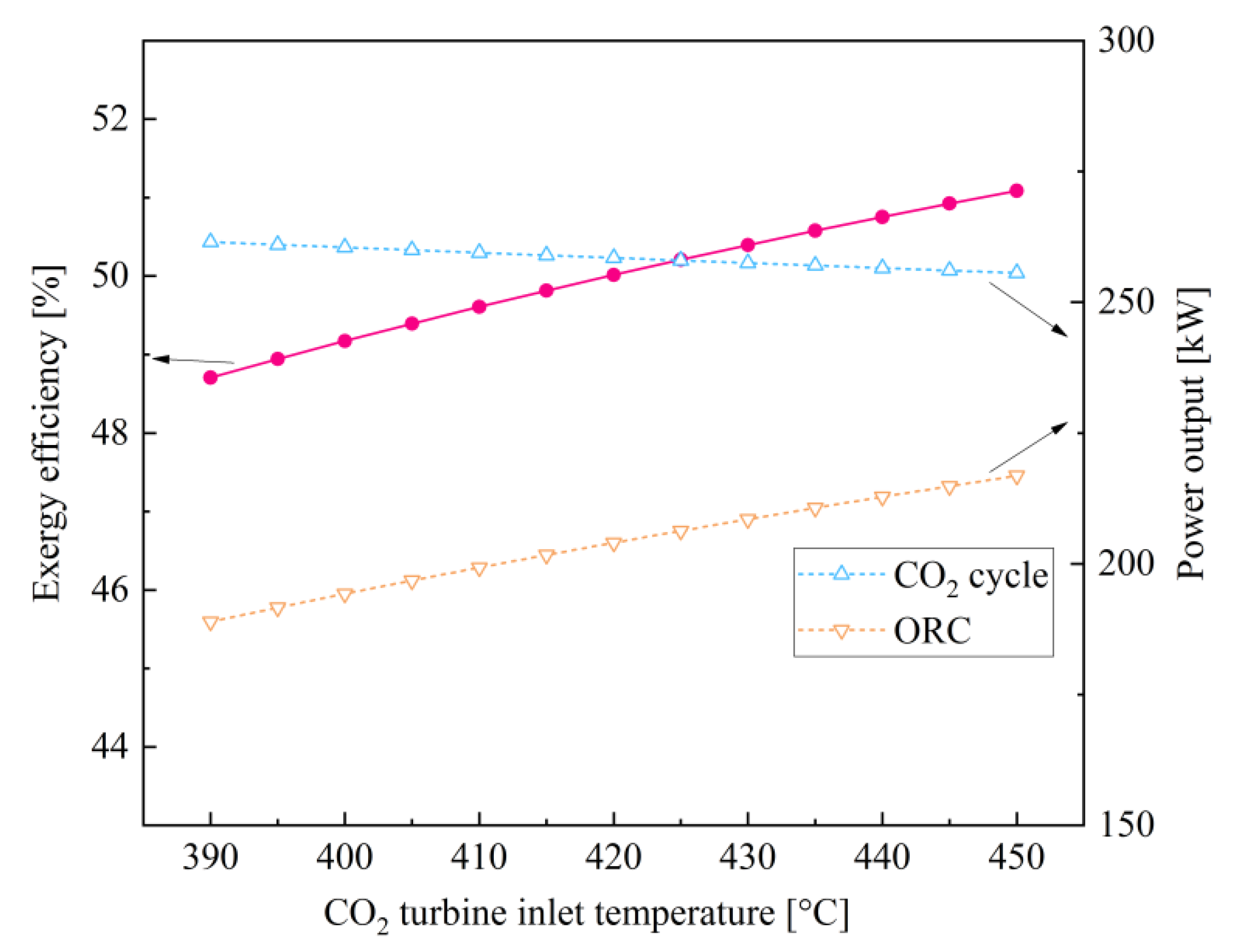
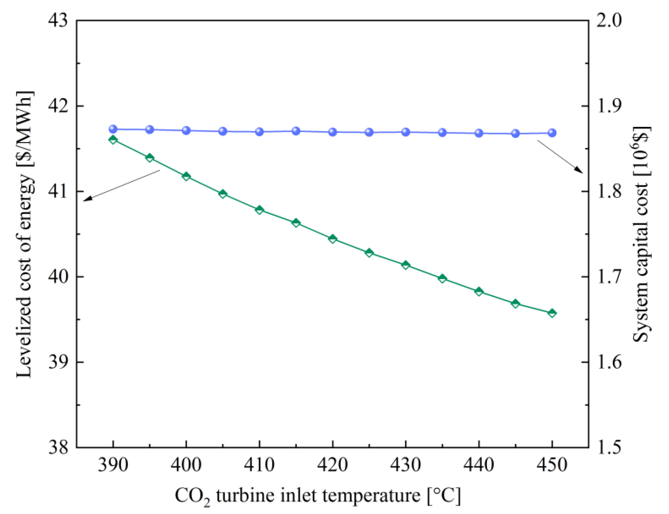
4.2. Effect of CO2 Turbine Inlet Temperature TCO2T,in

The effect of TCO2T,in on the system performance is shown in Figure 4 and Figure 5. A higher gas temperature is advantageous for turbine power generation. Simultaneously, the increase in the CO2 temperature heated in the gas heater diminishes the CO2 mass in the case of the constant heat source condition. The power generation by CO2 turbine is thus reduced, due mainly to the dominant function of the variation in CO2 mass flow. Of course, the compressor power input is diminished because its operation parameters are independent of TCO2T,in. As for the transcritical ORC, the organic fluid mass is raised owing to the increased heat capacity in the IHE. In consequence, the pump power consumption and ORC turbine power generation are elevated. It is thus interesting to find in Figure 4 that the curve of power output by the CO2 subcycle presents a decreasing trend with TCO2T,in while the ORC cycle gives more power output. Because the change in ORC power generation has a dominant influence, the system exergy efficiency increases monotonically with an increment value of 2.38% when the examined temperature increases from 390 to 450 °C. Meanwhile, a reverse variation trend can be found in Figure 5 for the system LCOE with a decrement of 2.03 USD/MWh because of the almost unchanged total capital cost.

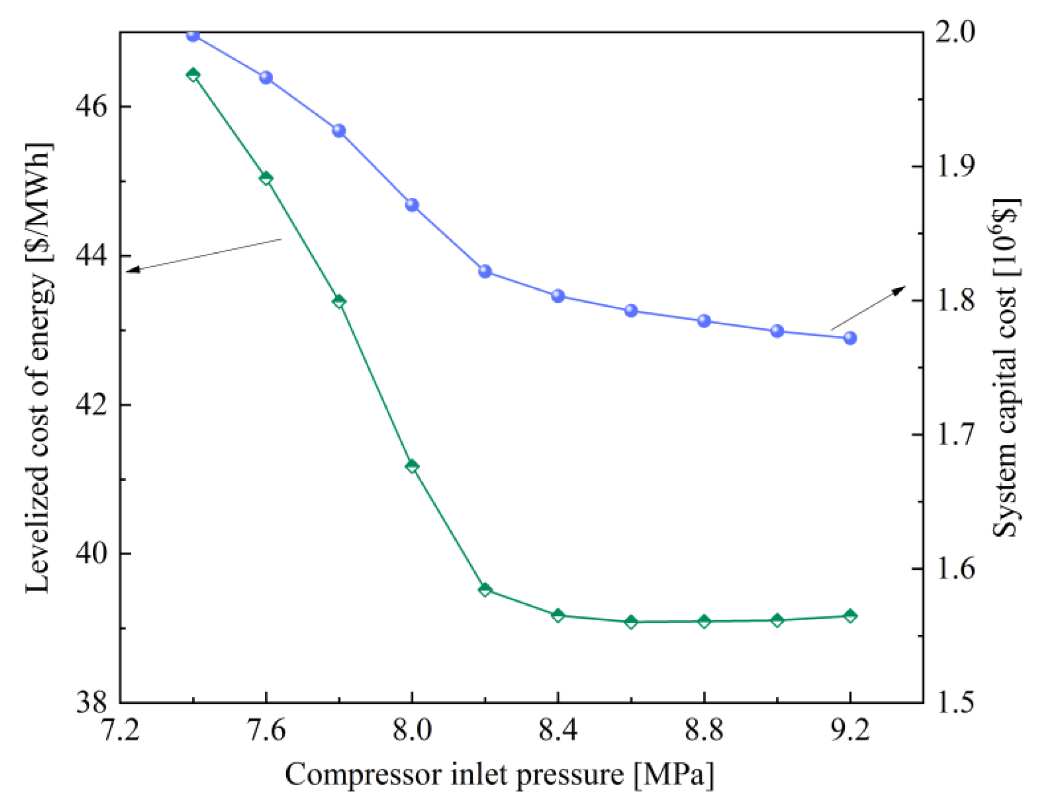
4.3. Effect of Compressor Inlet Pressure pC,in

The variations of system performance are illustrated in Figure 6 and Figure 7 by changing pC,in from 7.4 to 9.2 MPa. A maximum value for system exergy efficiency when pC,in is at 8.2 MPa in the examined case can be found. For pC,in lower than the optimized value, exergy efficiency is provided with a sharp decrease from 49.88% to 46.56%, with a decrease in pC,in due mainly to the rapid ascend of compressor power consumption. Moreover, the total capital cost is also raised by reducing pC,in. Therefore, the LCOE is increased from 39.52 to 46.43 USD/MWh in a narrow range of pC,in. For pC,in higher than the optimized value, exergy efficiency experiences a decrease by increasing pC,in due mainly to the shrunken specific enthalpy change through CO2 turbine, while the decreasing trend is relatively slower. Meanwhile, the total capital cost also experiences a decreasing variation. In consequence, there is small change for LCOE by increasing pC,in to higher than the optimized value.

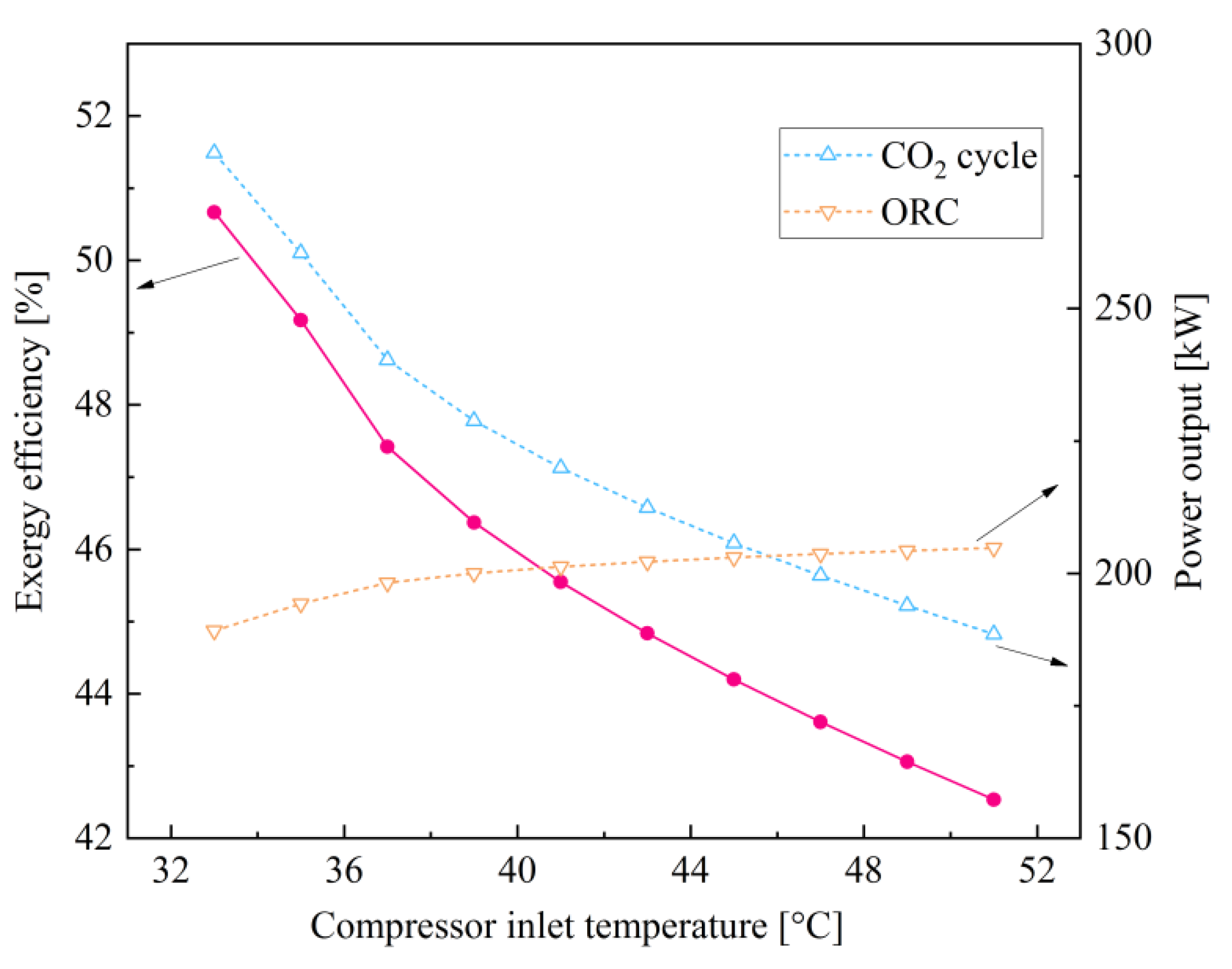
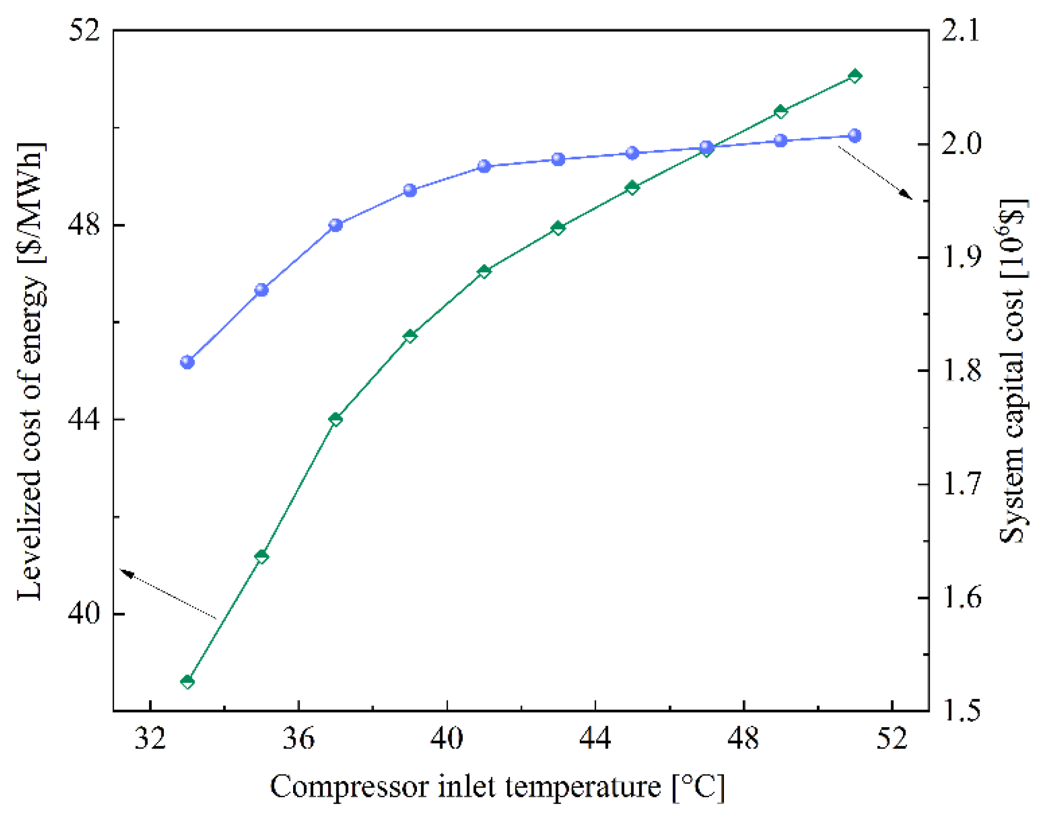
4.4. Effect of Compressor Inlet Temperature TC,in

The variations of system performance are illustrated in Figure 8 and Figure 9 by varying TC,in from 33 to 51 °C. It is found that the exergy efficiency is highly influenced by the variable TC,in, possessing a sharp decrease from 50.67% to 42.54%. This occurs because the increase in TC,in highly contributes to the power capacity required by the compressor. Furthermore, the total capital cost is raised because there is an increase in compressor power as well as the mass of CO2 and organic fluid. Consequently, the system LCOE benefits from a significant increase in general from 38.60 to 51.06 USD/MWh over an 18 °C range of TC,in. It can be suggested that the TC,in should be as low as possible without considering other factors.

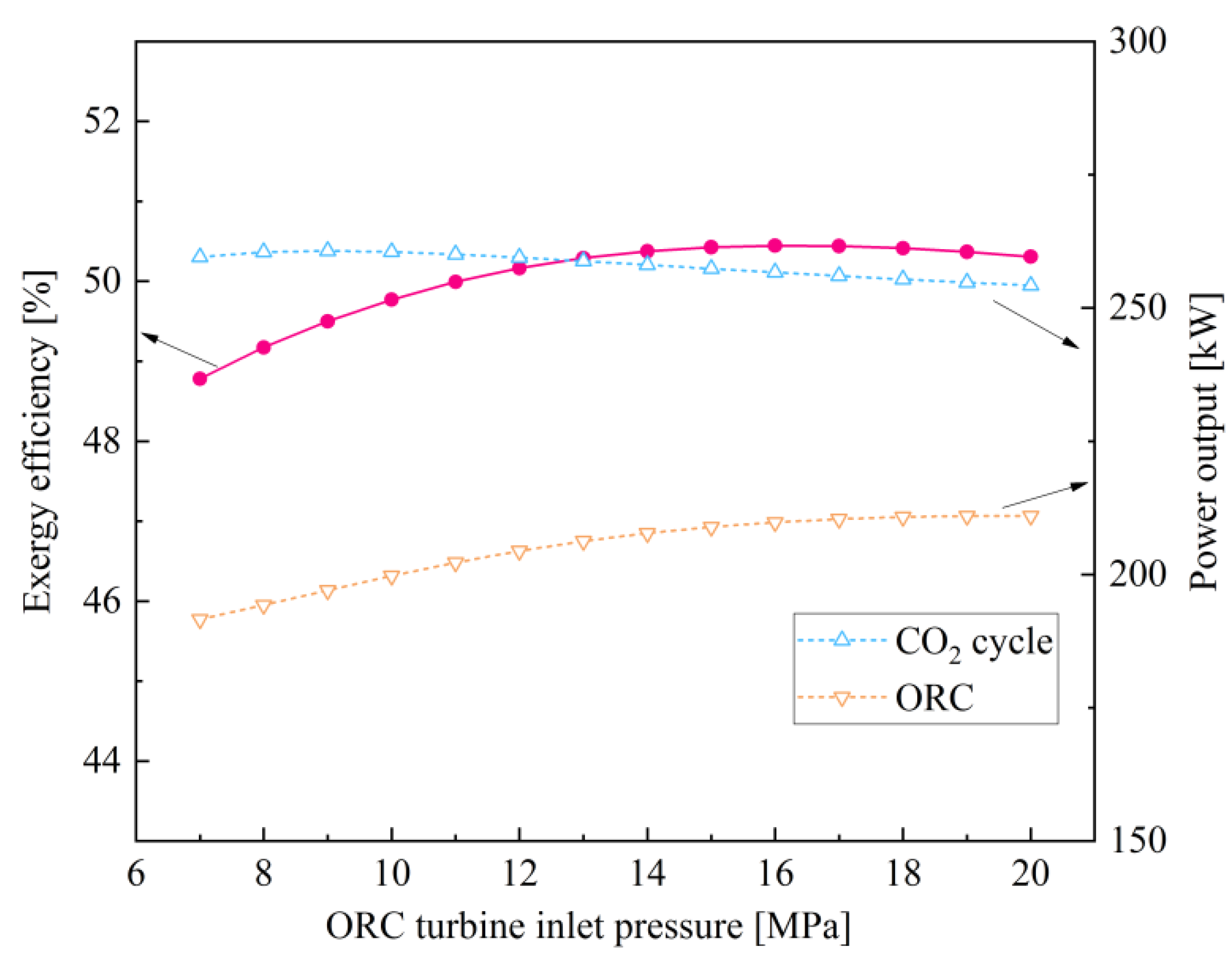
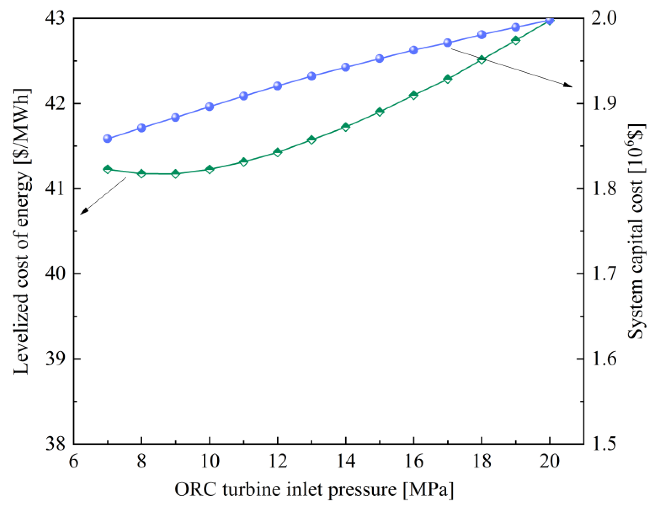
4.5. Effect of ORC Turbine Inlet Pressure pORCT,in

The key variable pORCT,in is assessed to find its influence on the performance variables, as shown in Figure 10 and Figure 11. By increasing this pressure, the temperature at ORC turbine exhaust will be lowered and this causes the drop of CO2 temperature entering the gas heater. Accordingly, the CO2 mass in the top cycle is reduced, which brings about the decrease in power capacities of CO2 turbine and compressor. Furthermore, the evenness of the specific heat capacity for supercritical organic fluid in the ORC regenerator becomes favorable by keeping away from the critical pressure gradually. The recuperated temperature grows instead, despite the descend of ORC turbine exhaust temperature, and this enhances the organic fluid mass owing to its dominant influence in the transcritical ORC. The increasing trend of power can therefore be expected for not only the ORC turbine but also the pump. By calculating the above four component powers, the evolution of the system exergy efficiency versus ORC turbine inlet pressure can be drawn in Figure 10, which benefits from a maximum exergy efficiency. As for the economic performance, in Figure 11, a monotonically increasing trend is indicated for the total capital cost as the main result of the increase in the cost of the ORC turbine and pump. Finally, it can be handily derived that there is a minimum value for the system LCOE through varying pORCT,in.

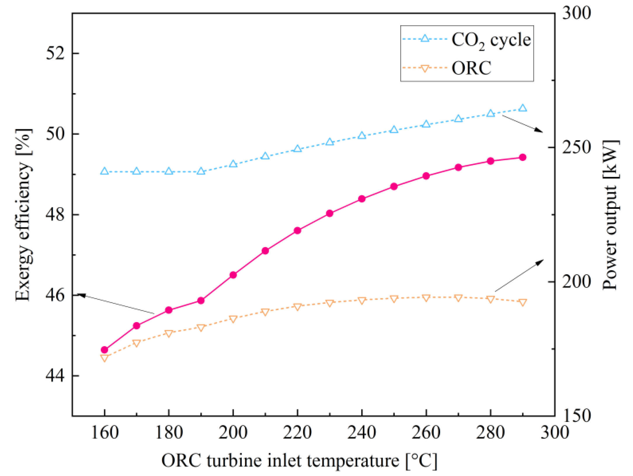
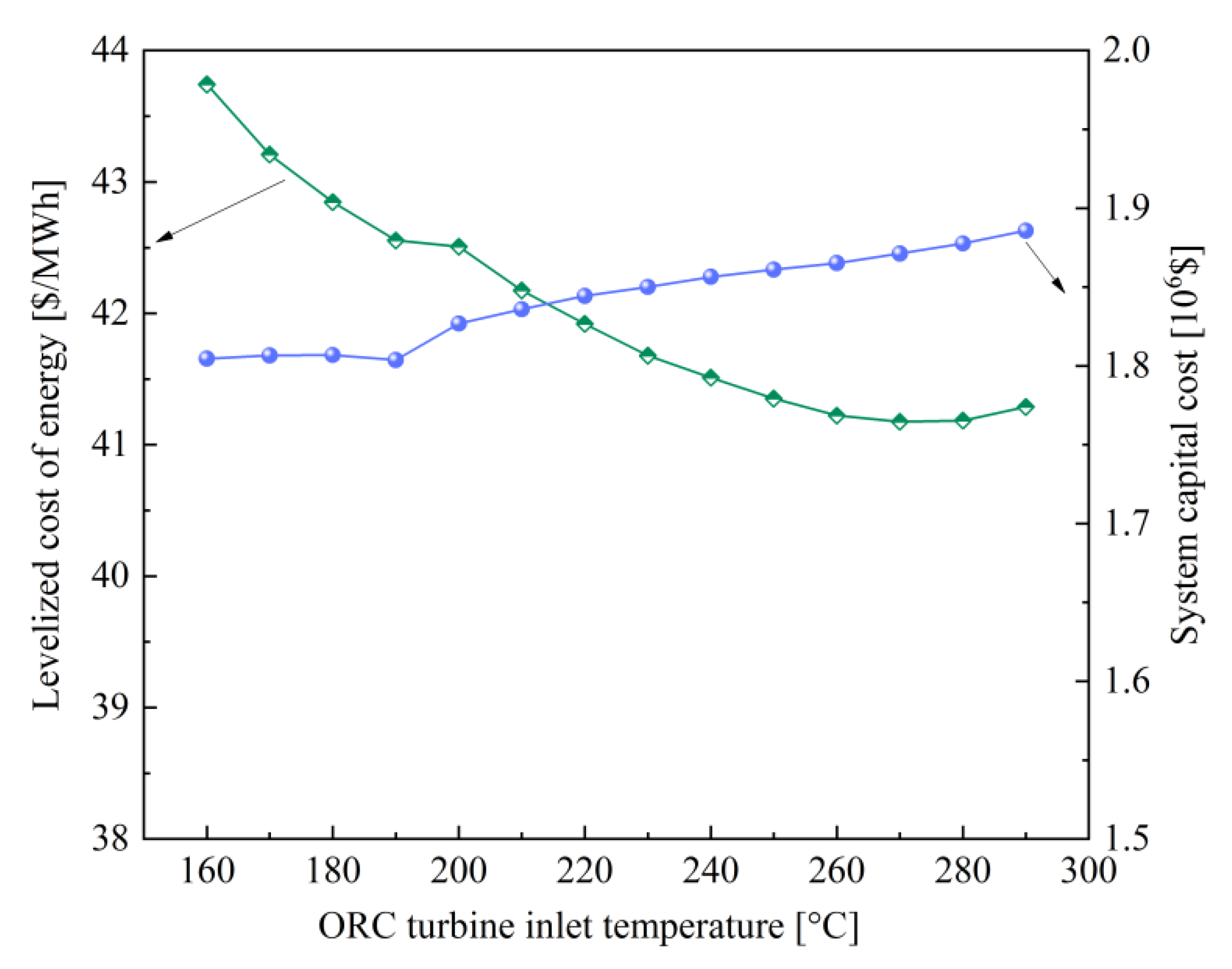
4.6. Effect of ORC Turbine Inlet Temperature TORCT,in

The influence of TORCT,in on system performance is shown in Figure 12 and Figure 13. It is understandable that a larger TORCT,in is beneficial to enhancing the turbine power generation. Nevertheless, the ORC turbine exhaust temperature goes up alongside with TORCT,in. This will finally reduce the working fluid in the transcritical ORC, owing to the constant heat source input in the IHE. Consequently, the power generation by ORC turbine creates little change and the pump input power significantly decreases with the increase in TORCT,in. Moreover, the power output by the CO2 Brayton cycle can be improved when the CO2 regenerator functions in the system. In general, the curve of the system exergy efficiency shows an increasing trend in Figure 12. Furthermore, it is demonstrated in Figure 13 that the system LCOE decreases with TORCT,in, due mainly to the dominant influence of exergy efficiency variation over the total capital cost change.

4.7. Multi-Objective Optimization

It is in fact not only thermal behavior but also economical characteristics that should be focused on when a novel thermal system is proposed. It is often impossible to achieve the best design parameters to reach the largest efficiency and the lowest investment simultaneously. The best operation conditions of one objective usually leads to the wrong solution to other objectives. This indicates that the thermodynamic performance and economic performance should be in a trade-off during the optimization process of the operation solutions for the proposed system. A set of optimal solutions that is termed as the Pareto frontier can be obtained through multi-objective optimization. System exergy efficiency and LCOE are the two objectives in the optimization performed in the study. The key parameters, i.e., pCO2T,in (17–25 MPa), TCO2T,in (350–450 °C), pCO2,in (7–20 MPa), the hot end temperature difference in IHE (10–100 °C), pC,in (7.4–9.2 MPa), and TC,in (33–51 °C), are specified as the variables to be optimized. The genetic algorithm, which is a type of robust method, is employed as the optimization approach, and is subject to specifications (population size 40, cross-over factor 0.8, mutation factor 0.05, and generation number 200).
The multi-objective optimization results for the system performance objectives are depicted in Figure 14, which shows the Pareto frontier expressing the exergy efficiency with horizontal coordinate and the LCOE with vertical coordinate. It is generally indicated that LCOE increases alongside the rise in exergy efficiency. The exergy efficiency arrives at its lowest at point A (53.80%), where LCOE also benefits from its lowest value (36.61 USD/MWh). At point B, the cycle possesses the largest exergy efficiency and LCOE (55.16% and 37.44 USD/MWh). Furthermore, because all the Pareto frontier points are the optimal working conditions based on different policy makers, the Technique for Order Preference by Similarity to an Ideal Solution (TOPSIS) approach [32] is applied herein to determine the optimal variables. There are two hypothetical points predefined in TOPSIS. At the ideal point, both objective functions reach their best values, i.e., the largest exergy efficiencies and the smallest LCOE, while the targets achieve the worst values at the worst point. These two virtual points are not on the Prato frontier curve and thus the optimal point after optimization is defined by taking the Pareto frontier solution point of the furthest distance to the worst point and the nearest distance to the ideal point. The corresponding exergy efficiency and LCOE are 54.63% and 36.95 USD/MWh, respectively. The optimized decision and performance variables are shown in Table 4.

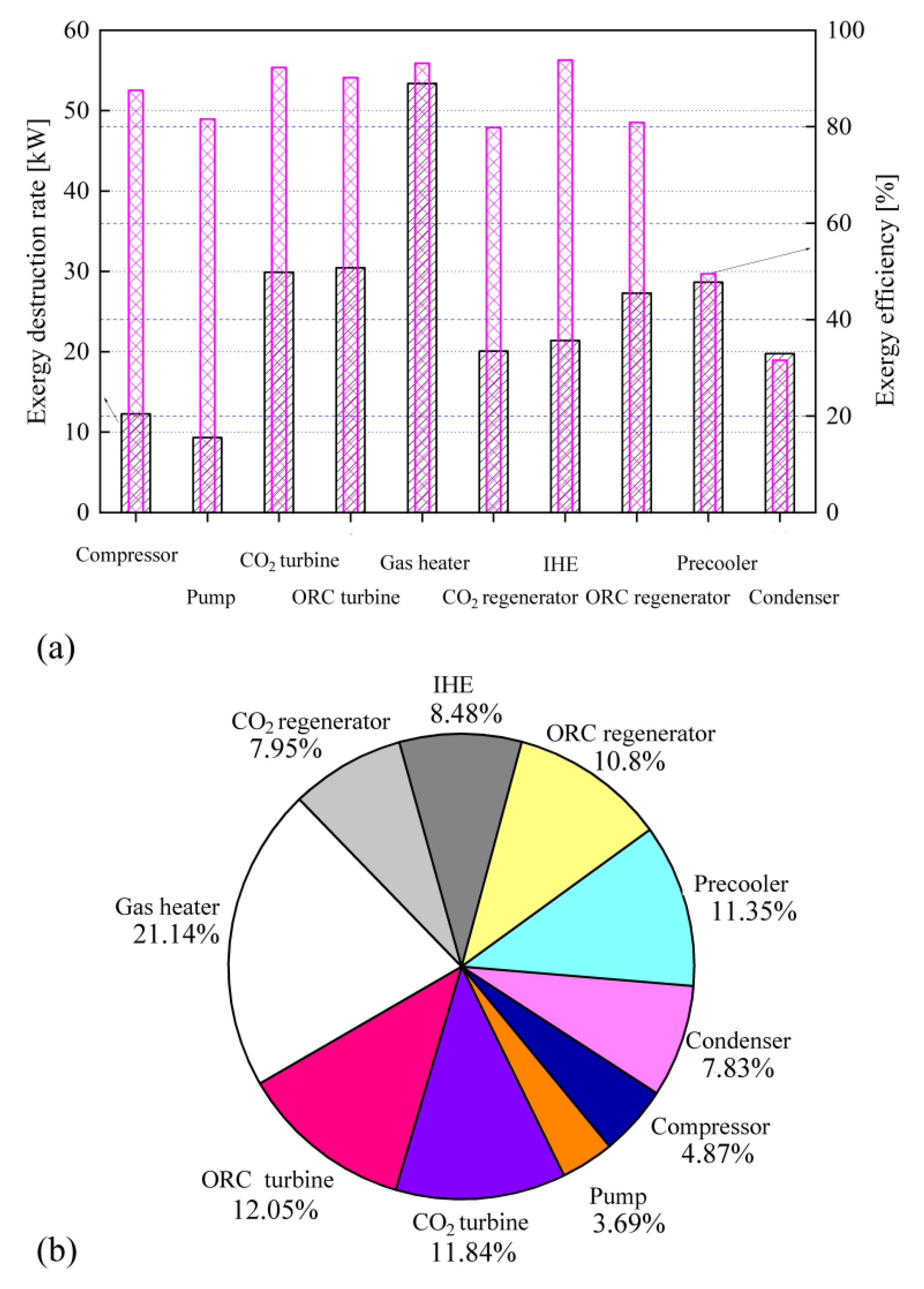
4.8. Exergy Distribution at Optimized Condition

Figure 15 shows the system inefficiencies occurring in the process of energy conversion and transportation. It can be found that the highest irreversible loss takes place in the gas heater, taking 21.14% of the total exergy destruction. This occurs mainly due to the extensive minimal temperature difference presented and the great heat transport capacity. The precooler and ORC regenerator contribute the second (11.35%) and third (10.8%) highest capacity of irreversible loss amongst the system heat exchangers. However, one may suggest that the ORC regenerator should be given more attention than the precooler, in order to elevate the system efficiency, because the precooler is essentially a dissipation component in the proposed system. With respect to the turbomachinery, the ORC turbine and CO2 turbine benefit from the priority for improvement, owing to their much higher exergy destruction compared to the compressor and pump, despite the larger component exergy efficiency.

4.9. Discussion

For high-temperature waste heat recovery, the ORC cannot be directly used, considering the thermal stability and safety of organic fluids. For transcritical CO2 Rankine cycle, the main issue is how to effectively condense the subcritical CO2 with ambient cooling sources in consideration of the low critical temperature. System miniaturization is a strict requirement for the waste heat recovery cycle of engines. The working fluid in the supercritical state is provided with favorable heat transfer performance and high density, which enables compact designs of turbo-machinery and heat exchanger. The integrated system combing with supercritical CO2 Brayton cycle and transcritical ORC may be an interesting solution to recycle engine waste heat for its compact configuration, stability, and high thermal efficiency.

5. Conclusions

(1)
A new power system is proposed by integrating supercritical CO2 Brayton cycle and transcritical ORC, which is eco-friendly, compact, stable, and highly efficient.
(2)
The increase in the CO2 turbine inlet pressure and temperature is positive for system performance. There is an optimized compressor inlet pressure associated with exergy efficiency. The compressor inlet temperature should be as low as possible.
(3)
There is a maximum value of system exergy efficiency and minimum value of levelized cost of energy by varying the ORC turbine inlet pressure. The increase in ORC turbine inlet temperature improves the system exergy efficiency and reduces the levelized cost of energy.
(4)
The determined exergy efficiency and levelized cost of energy in the proposed system are 54.63% and 36.95 USD/MWh after multi-objective optimization.

Author Contributions

Conceptualization, Z.L.; methodology, H.M.; software, Z.L.; validation, H.M.; formal analysis, H.M.; investigation, Z.L. and H.M.; resources, Z.L.; data curation, H.M.; writing—original draft preparation, H.M.; writing—review and editing, Z.L.; visualization, H.M.; supervision, Z.L.; project administration, Z.L.; funding acquisition, Z.L. All authors have read and agreed to the published version of the manuscript.

Funding

This research received no external funding.

Institutional Review Board Statement

Not applicable.

Informed Consent Statement

Not applicable.

Data Availability Statement

Not applicable.

Conflicts of Interest

The authors declare no conflict of interest.

References

  1. Berardi, U. Building energy consumption in US, EU, and BRIC countries. Proc. Eng. 2015, 118, 128–136. [Google Scholar] [CrossRef] [Green Version]
  2. Steinmann, W.D. Thermo-mechanical concepts for bulk energy storage. Renew. Sustain. Energy Rev. 2017, 75, 205–219. [Google Scholar] [CrossRef]
  3. Morgan, R.; Dong, G.Y.; Panesar, A.; Heikal, M. A comparative study between a Rankine cycle and a novel intra-cycle based waste heat recovery concepts applied to an internal combustion engine. Appl. Energy 2016, 174, 108–117. [Google Scholar] [CrossRef] [Green Version]
  4. Rahbar, K.; Mahmoud, S.; Al-Dadah, R.K.; Moazami, N.; Mirhadizadeh, S.A. Review of organic Rankine cycle for small-scale applications. Energy Convers. Manag. 2017, 134, 135–155. [Google Scholar] [CrossRef]
  5. Sun, W.; Yue, X.; Wang, Y. Exergy efficiency analysis of ORC (Organic Rankine Cycle) and ORC-based combined cycles driven by low-temperature waste heat. Energy Convers. Manag. 2017, 135, 63–73. [Google Scholar] [CrossRef]
  6. Tian, H.; Shu, G.; Wei, H.; Liang, X.; Liu, L. Fluids and parameters optimization for the organic Rankine cycles (ORCs) used in exhaust heat recovery of Internal Combustion Engine (ICE). Energy 2012, 47, 125–136. [Google Scholar] [CrossRef]
  7. Su, X.; Shedd, T.A. Towards working fluid properties and selection of Rankine cycle based waste heat recovery (WHR) systems for internal combustion engines-a fundamental analysis. Appl. Therm. Eng. 2018, 142, 502–510. [Google Scholar] [CrossRef]
  8. Vaja, I.; Gambarotta, A. Internal Combustion Engine (ICE) bottoming with Organic. Rankine. Cycles (ORCs). Energy 2010, 35, 1084–1093. [Google Scholar] [CrossRef]
  9. Kim, M.; Shin, G.; Kim, G.; Cho, B. Single-loop organic Rankine cycle for engine waste heat recovery using both low-and high-temperature heat sources. Energy 2016, 96, 482–494. [Google Scholar] [CrossRef]
  10. Wang, X.; Shu, G.; Tian, H.; Liu, P.; Jing, D.; Li, X. Dynamic analysis of the dual-loop Organic Rankine Cycle for waste heat recovery of a natural gas engine. Energy Convers. Manag. 2017, 148, 724–736. [Google Scholar] [CrossRef]
  11. Ping, X.; Yao, B.F.; Zhang, H.G.; Yang, F.B. Thermodynamic, economic, and environmental analysis and multi-objective optimization of a dual loop organic Rankine cycle for CNG engine waste heat recovery. Appl. Therm. Eng. 2021, 193, 1169–1180. [Google Scholar] [CrossRef]
  12. Civgin, M.G.; Deniz, C. Analyzing the dual-loop organic Rankine cycle for waste heat recovery of container vessel. Appl. Therm. Eng. 2021, 199, 1175–1182. [Google Scholar] [CrossRef]
  13. Schuster, A.; Karellas, S.; Aumann, R. Efficiency optimization potential in supercritical Organic Rankine Cycles. Energy 2010, 35, 1033–1049. [Google Scholar] [CrossRef]
  14. Yang, M.H. Thermal and economic analyses of a compact waste heat recovering system for the marine diesel engine using trascritical Rankine cycle. Energy Convers. Manag. 2015, 106, 1082–1096. [Google Scholar] [CrossRef]
  15. Yağlı, H.; Koç, Y.; Koç, A.; Görgülü, A.; Tandiroğlu, A. Parametric optimization and exergetic analysis comparison of subcritical and supercritical organic Rankine cycle (ORC) for biogas fuelled combined heat and power (CHP) engine exhaust gas waste heat. Energy 2016, 111, 923–932. [Google Scholar] [CrossRef]
  16. Wang, E.; Yu, Z.; Zhang, H.; Yang, F. A regenerative supercritical dual-loop organic Rankine cycle system for energy recovery from the waste heat of internal combustion engines. Appl. Energy 2017, 190, 574–590. [Google Scholar] [CrossRef]
  17. Shi, L.; Shu, G.; Tian, H.; Deng, S. A review of modified Organic Rankine cycles (ORCs) for internal combustion engine waste heat recovery (ICE-WHR). Renew. Sustain. Energy Rev. 2018, 92, 95–110. [Google Scholar] [CrossRef]
  18. Rajabloo, T.; Bonalumi, D.; Lora, P. Effect of a partial thermal decomposition of the working fluid on the performances of ORC power plants. Energy 2017, 133, 1013–1026. [Google Scholar] [CrossRef]
  19. EI-Harbawi, M.; Shaaran, S.; Ahmad, F.; Wahi, M.; Abdul, A.; Larid, D.; Yi, C.-H. Estimating the flammability of vapours above refinery wastewater laden with hydrocarbon mixtures. Fire Saf. J. 2012, 51, 61–67. [Google Scholar] [CrossRef] [Green Version]
  20. Astolfi, M.; Alfani, D.; Lasala, S.; Macchi, E. Comparison between ORC and CO2 power systems for the exploitation of low-medium temperature heat sources. Energy 2018, 161, 1250–1261. [Google Scholar] [CrossRef]
  21. Meng, F.X.; Wang, E.H.; Zhang, B.; Zhang, F.J.; Zhao, C.L. Thermo-economic analysis of transcritical CO2 power cycle and comparison with Kalina cycle and ORC for a low temperature heat source. Energy Convers. Manag. 2019, 195, 1295–1308. [Google Scholar] [CrossRef]
  22. Yu, G.; Shu, G.; Tian, H.; Huo, Y.; Zhu, W. Experimental investigations on a cascaded steam-/organic-Rankine-cycle (RC/ORC) system for waste heat recovery (WHR) from diesel engine. Energy Convers. Manag. 2016, 129, 43–51. [Google Scholar] [CrossRef]
  23. Zhang, C.; Shu, G.; Tian, H.; Wei, H.; Liang, X. Comparative study of alternative ORC based combined power systems to exploit high temperature waste heat. Energy Convers. Manag. 2015, 89, 541–554. [Google Scholar] [CrossRef]
  24. Liu, Z.; Liu, X.; Zhang, W.F.; Yang, S.J.; Li, H.L.; Yang, X.H. Thermodynamic analysis on the feasibility of a liquid energy storage system using CO2-based mixture as the working fluid. Energy 2022, 238, 1217–1229. [Google Scholar] [CrossRef]
  25. Shu, G.Q.; Yu, Z.G.; Tian, H.; Liu, P.; Xu, Z.Q. Potential of the transcritical Rankine cycle using CO2-based binary zeotropic mixtures for engine’s waste heat recovery. Energy Convers. Manag. 2018, 174, 668–685. [Google Scholar] [CrossRef]
  26. Liu, Z.; Liu, Z.H.; Xin, X.; Yang, X.H. Proposal and assessment of a novel carbon dioxide energy storage system with electrical thermal storage and ejector condensing cycle: Energy and exergy analysis. Appl. Energy 2020, 269, 1150–1167. [Google Scholar] [CrossRef]
  27. Liu, Z.; Liu, Z.H.; Yang, X.Q.; Zhai, H.Y.; Yang, X.H. Advanced exergy and exergoeconomic analysis of a novel liquid carbon dioxide energy storage system. Energy Convers. Manag. 2020, 205, 1123–1131. [Google Scholar] [CrossRef]
  28. Liu, Z.; Liu, Z.H.; Cao, X.; Li, H.L.; Yang, X.H. Self-condensing transcritical CO2 cogeneration system with extraction turbine and ejector refrigeration cycle: A techno-economic assessment study. Energy 2020, 208, 1183–1191. [Google Scholar] [CrossRef]
  29. Cayer, E.; Galanis, N.; Desilets, M.; Nesreddine, H.; Roy, P. Analysis of a carbon dioxide transcritical power cycle using a low teperature source. Appl. Energy 2009, 86, 1055–1063. [Google Scholar] [CrossRef]
  30. Ipakchi, O.; Mosaffa, A.H.; Farshi, L.G. Ejector based CO2 transcritical combined cooling and power system utilizing waste heat recovery: A thermoeconomic assessment. Energy Convers. Manag. 2019, 186, 462–472. [Google Scholar] [CrossRef]
  31. Morandin, M.; Mercangöz, M.; Hemrle, J.; Maréchal, F.; Favrat, D. Thermoeconomic design optimization of a thermo-electric energy storage system based on transcritical CO2 cycles. Energy 2013, 58, 571–587. [Google Scholar] [CrossRef]
  32. Lemmon, E.W.; Huber, M.L.; McLinden, M.O. NIST Standard Reference Database 23: Reference Fluid Thermodynamic and Transport Properties-REFPROP, Version 9.1; National Institute of Standards and Technology, Standard Reference Data Program: Gaithersburg, ML, USA, 2013.
  33. Huang, W.G.; Wang, J.F.; Xia, J.X.; Zhao, P.; Dai, Y.P. Performance analysis and optimization of a combined cooling and power system using low boiling point working fluid driven by engine waste heat. Energy Convers. Manag. 2019, 180, 962–976. [Google Scholar] [CrossRef]
Figure 1. Structure of proposed thermal power cycle.
Sustainability 14 01276 g001
Figure 2. Effect of pCO2T,in on thermodynamic performance.
Sustainability 14 01276 g002
Figure 3. Effect of pCO2T,in on economic performance.
Sustainability 14 01276 g003
Figure 4. Effect of TCO2T,in on thermodynamic performance.
Sustainability 14 01276 g004
Figure 5. Effect of TCO2T,in on economic performance.
Sustainability 14 01276 g005
Figure 6. Effect of pC,in on thermodynamic performance.
Sustainability 14 01276 g006
Figure 7. Effect of pC,in on economic performance.
Sustainability 14 01276 g007
Figure 8. Effect of TC,in on thermodynamic performance.
Sustainability 14 01276 g008
Figure 9. Effect of TC,in on economic performance.
Sustainability 14 01276 g009
Figure 10. Effect of pORCT,in on thermodynamic performance.
Sustainability 14 01276 g010
Figure 11. Effect of pORCT,in on economic performance.
Sustainability 14 01276 g011
Figure 12. Effect of TORCT,in on thermodynamic performance.
Sustainability 14 01276 g012
Figure 13. Effect of TORCT,in on economic performance.
Sustainability 14 01276 g013
Figure 14. Pareto frontier distribution after optimization.
Sustainability 14 01276 g014
Figure 15. Distribution of the system inefficiencies at the optimized point: (a) exergy destruction and component efficiency; (b) relative exergy destruction.
Sustainability 14 01276 g015
Table 1. Fuel and product exergies to main equipment.
EquipmentFuel Exergy Product Exergy
Gas heater E ˙ 14 E ˙ 15 E ˙ 4 E ˙ 3
CO2 Turbine E ˙ 4 E ˙ 5 W ˙ T C O 2
CO2 regenerator E ˙ 6 E ˙ 7 E ˙ 3 E ˙ 2
Precooler E ˙ 7 E ˙ 1 E ˙ 17 E ˙ 16
Compressor W ˙ C E ˙ 2 E ˙ 1
IHE E ˙ 5 E ˙ 6 E ˙ 11 E ˙ 10
ORC turbine E ˙ 11 E ˙ 12 W ˙ T O R C
ORC regenerator E ˙ 12 E ˙ 13 E ˙ 10 E ˙ 9
Condenser E ˙ 13 E ˙ 8 E ˙ 19 E ˙ 18
Pump W ˙ P E ˙ 9 E ˙ 8
Table 2. Cost function parameter. Adapted with permission from Ref. [31]. Copyright 2013 Elsevier.
Componenty1y2z
Turbine900040,0000.69
Compressor900020,0000.6
Pump150050,0000.8
Heat exchanger90010,0000.82
Table 3. Design variables of the power system.
ParameterValue
Ambient pressure (MPa)0.1013
Ambient temperature (°C)20
Mass flow of exhaust gas (kg/s)4.35
Temperature of exhaust gas (°C)470
Inlet pressure of CO2 turbine (MPa)20
Compressor inlet pressure (MPa)8
Inlet temperature of CO2 turbine (°C) 400
Compressor inlet temperature (°C) 35
Inlet pressure of ORC turbine (MPa)8
Inlet temperature of ORC turbine (°C)270
Condensation temperature (°C)35
Turbine isentropic efficiency0.85
Compressor isentropic efficiency 0.85
Pump isentropic efficiency0.8
Temperature difference in gas heater (°C)20
Temperature difference in precooler, 10
IHE, regenerator and condenser (°C)
Table 4. Optimized values of decision parameters.
ParametersValue
pCO2T,in (MPa)20.78
TCO2T,in (°C)431.57
pORCT,in (MPa)17.25
TORCT,in (°C)308.47
Exergy efficiency (%)54.63
LCOE (USD/MWh)36.95
Publisher’s Note: MDPI stays neutral with regard to jurisdictional claims in published maps and institutional affiliations.

