Article

Study on Elastoplastic Damage Coupling of Reservoir Mudstone Considering Permeability Change

1
College of Pipeline and Civil Engineering, China University of Petroleum (East China), Qingdao 266580, China
2
Hunan Provincial Key Laboratory of Key Technology on Hydropower Development, Zhongnan Engineering Corporation, Changsha 410014, China
*
Author to whom correspondence should be addressed.
Sustainability 2022, 14(20), 13507; https://doi.org/10.3390/su142013507
Submission received: 15 August 2022 / Revised: 28 September 2022 / Accepted: 17 October 2022 / Published: 19 October 2022
(This article belongs to the Special Issue Deep Mining Engineering in Sustainability)

Abstract

:
Mudstone, a common complex medium in oil and gas reservoirs and with widely distributed micro-pore and micro-fissures, is liable to produce significant damage evolution and plastic deformation under high buried depth stress environments. Based on the analysis of the physical characteristics, the elastoplastic damage coupling mechanical characteristics of mudstone in a high buried depth reservoir for oil and gas engineering are discussed. Firstly, conventional triaxial compression tests under different confining pressures were performed to calculate the damage variable and obtain the damage evolution. The damage evolution included the elastic damage stage, the plastic-dominated elastoplastic damage coupling stage and the damage-dominated elastoplastic damage coupling stage. Secondly, a coupled elastoplastic damage mechanical model for mudstone was proposed, which was based on the degradation of the damage stiffness and plastic flow caused by the plastic and damage internal variables and considered the elastic damage coupling and elastoplastic damage coupling during the loading process. Thirdly, the elastoplastic damage coupling mechanical characteristics of mudstone were simulated. The simulation results are in good agreement with the experimental results, which reflects well the mechanical characteristics of mudstone, including the transition from volume compression to expansion, plastic hardening, damage softening and residual strength, etc. Finally, based on the relevant research results, a permeability evolution model of mudstone based on the damage was proposed, and the secondary development was carried out based on ABAQUS. UMAT and USFLD subroutines were compiled, and seepage–stress coupling simulation verification was carried out. The relevant results provide a reliable basis for engineering theory research and stability analysis of deep mudstone reservoirs.

1. Introduction

Mudstone reservoirs are the new key research objectives of oilfield exploration and development. As a source rock solidified by mud, clay and gypsum, the mudstone minerals in the reservoir are microcrystalline, with a complex internal structure and a wide distribution of micropores and fissures and are rich in organic matter [1,2]. Under the action of deep high ground stress, the micro-pores and fissures in mudstone are easy to expand and penetrate, and the damage evolution and plastic deformation of the structure occur. The mechanical properties deteriorate which leads to a significant decrease in the strength of the reservoir and plays a controlling role in casing damage [3,4]. Therefore, mudstone is the key research object of oil and gas exploitation engineering in high buried depth environments.
Damage evolution is the process of rock micro-defect expansion and coalescence under external load and the environment. It can reflect the degree of the deterioration of rock properties [5] and is also the basis for the construction of models of damage mechanics. Conil et al. [6] used the strain equivalence principle to consider the coupling relationship between plastic deformation and damage and proposed the thermodynamic model of plastic damage. Zhou et al. [7] developed an elastoplastic damage constitutive model with double yield surfaces based on the irreversible thermodynamics theory and damage mechanics theory for saturated soft rock. Zhou [8] developed a micro-mechanics-based model to investigate the micro-crack damage mechanism of the four stages of brittle rock under rotation of the principal stress axes. Zhao et al. [9] developed a damage-based constitutive formula for an overstress model which can be appropriately applied to the analysis of full dynamic stress–strain curves. Unteregger et al. [10] presented a constitutive model for describing the non-linear mechanical behavior of different types of intact rock subjected to complex 3D stress states, which is formulated on the basis of a combination of plasticity theory and the theory of damage mechanics along the lines of a damage plastic model for concrete. Liu et al. [11] proposed a damage constitutive model to describe the deformation and strength characteristics of intermittent jointed rocks under cyclic uniaxial compression, which can reflect the coupled damage induced by micro-flaws and macro-joints. Wu et al. [12] developed a damage evolution model with respect to the volumetric strain and a differential elastoplastic constitutive equation based on the relationship between the evolving permeability and porosity and the volumetric strain. Zhang et al. [13] described damage evolution using the Kachanov damage theory and obtained the damage evolution equation and the constitutive model of rock mass under multi-stage creep load considering the initial damage. Wu et al. [14] established a continuous damage constitutive model based on the framework of continuum damage mechanics and a strain equivalence hypothesis. The above achievements are mostly for brittle rocks and only consider the impact of elastic or plastic deformation on damage, without considering the coupling effect. The damage evolution of rock structure causes the friction sliding of fractures or joint surfaces, which forms the coupling effect of elastoplastic deformation and damage evolution. Therefore, it is of great theoretical significance to carry out the study of an elastoplastic damage coupling mechanical model.
In oil and gas exploration and development engineering, the reservoir will generate stress concentration under outside construction disturbance, and then the reservoir rock will generate elastic–plastic deformation and damage evolution. The mechanical properties of high buried depth reservoirs have high particularity and complexity [15]. With the increase in formation pressure, the strain borne by the reservoir rocks gradually increases, the damage evolution characteristics are more obvious, and the elastoplastic damage coupling effect is more obvious, showing the special mechanical properties of the brittle–ductile transformation that are different from shallow rocks [16]. At present, there is little research on the elastic–plastic damage coupling mechanical properties of rock under high buried depth environments. The only part of the research is mainly focused on granite and salt rock, with underground energy storage and nuclear waste disposal sites as the application target [17,18,19,20]. The research on the elastic–plastic damage coupling mechanical properties of mudstone in oil and gas reservoir engineering is basically blank. However, the coupling and superposition of the long-term high temperature and high pressure in high buried depth environments make the rock deformation and skeleton failure become particularly complex, and the coupling mechanical response of the elastoplastic damage becomes an urgent problem to be studied.
In actual petroleum engineering, mudstone is filled with pore fluid. Under the action of the external load, the stress field of mudstone changes, causing plastic deformation and damage of the rock mass. The internal microstructure changes, the skeleton particles are rearranged, and the primary pores and cracks gradually develop and penetrate, resulting in changes in material porosity and permeability. At the same time, the change in pore water pressure inside the deformed rock mass affects the mechanical parameters of mudstone. Therefore, the oil and gas exploitation process of mudstone reservoirs is a complex seepage–stress coupling process.
Based on this, this paper takes the mudstone of high buried depth reservoirs in oil and gas reservoir engineering as the research object. On the basis of a conventional triaxial compression test, damage evolution is discussed. Combined with Clausius–Duhan inequality in thermodynamics theory, the elastic–plastic damage coupling mechanical model was built, and then the simulation verification was carried out. Then, based on the relevant research results, the permeability evolution model of mudstone based on the damage was proposed, and the secondary development was carried out based on the finite element software ABAQUS. UMAT and USFLD subroutines were compiled, and the seepage–stress coupling simulation verification was carried out. The relevant results have important guiding significance for deep oil and gas exploitation engineering.

2. Conventional Triaxial Test of Mudstone

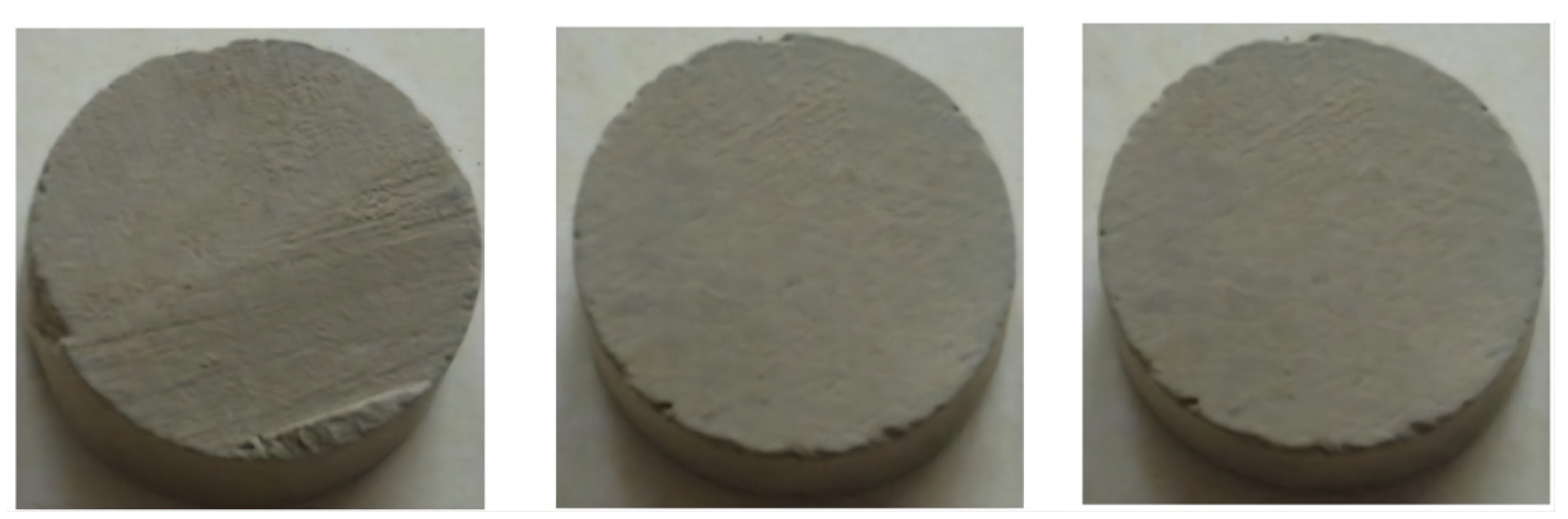
2.1. Lithology and Test Scheme

Mudstone belongs to soft rock, has good integrity (Figure 1), a gray color, no obvious lamination and a soft texture. It shows the phenomenon of weak consolidation, local loss of plasticity, no recrystallization and no immediate expansion in water. The related tests in this paper were performed using the rock automatic triaxial rheological servo instrument (Figure 2). The mudstone samples were taken from a Pushen block, Henan Province, China. The buried depth of the research reservoir mudstone is about 2.5–3.5 km, and the tested samples were cored in the vertical orientation of the bedding planes. The mudstone samples were prepared as cylindrical samples with a diameter of 25 mm and a height of 50 mm. Based on the geo-stress data in the sampling area, the conventional triaxial compression tests under the confining pressure of 10 MPa, 20 MPa and 30 MPa were carried out, and the axial stress loading rate was 0.75 MPa/min.

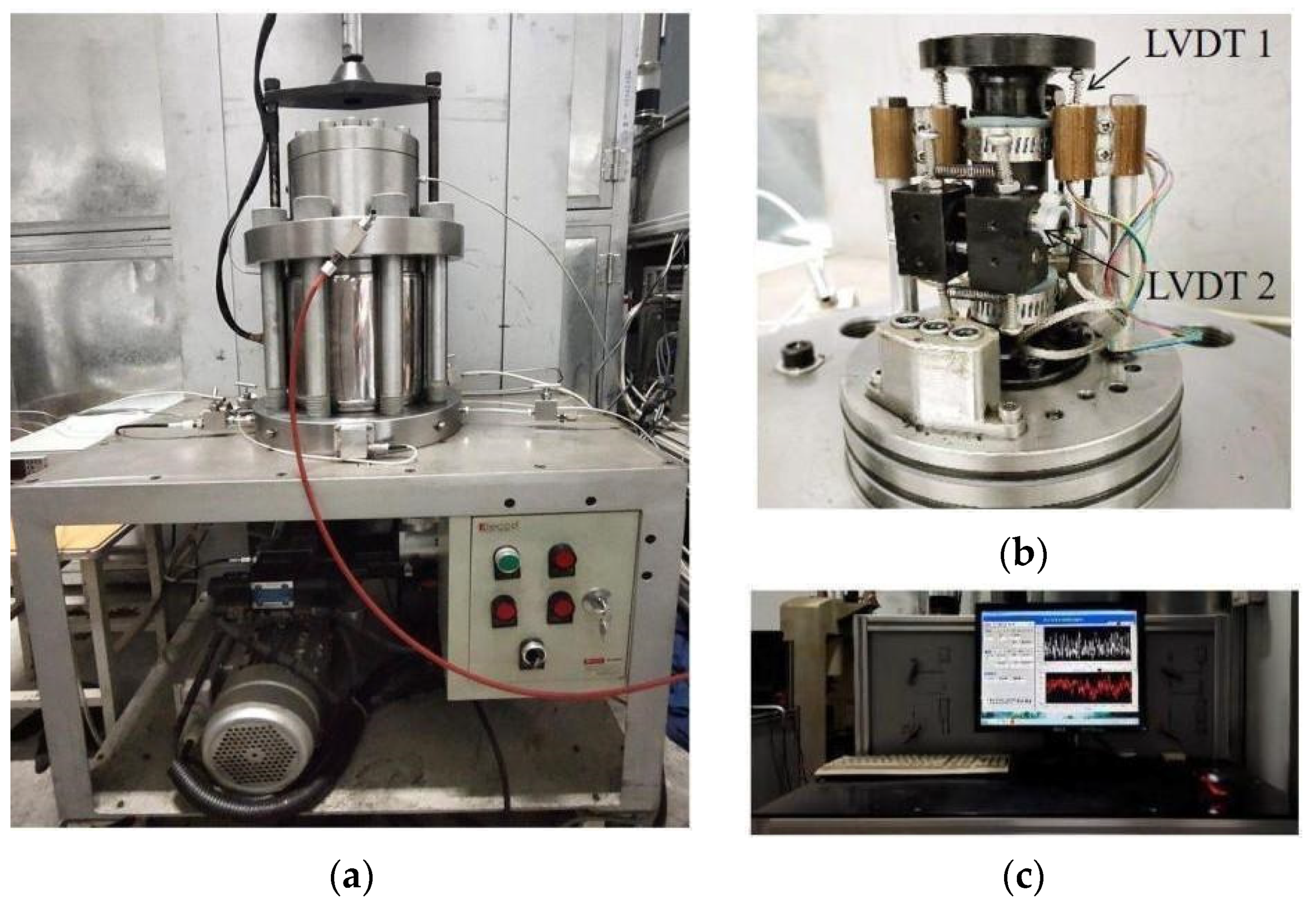
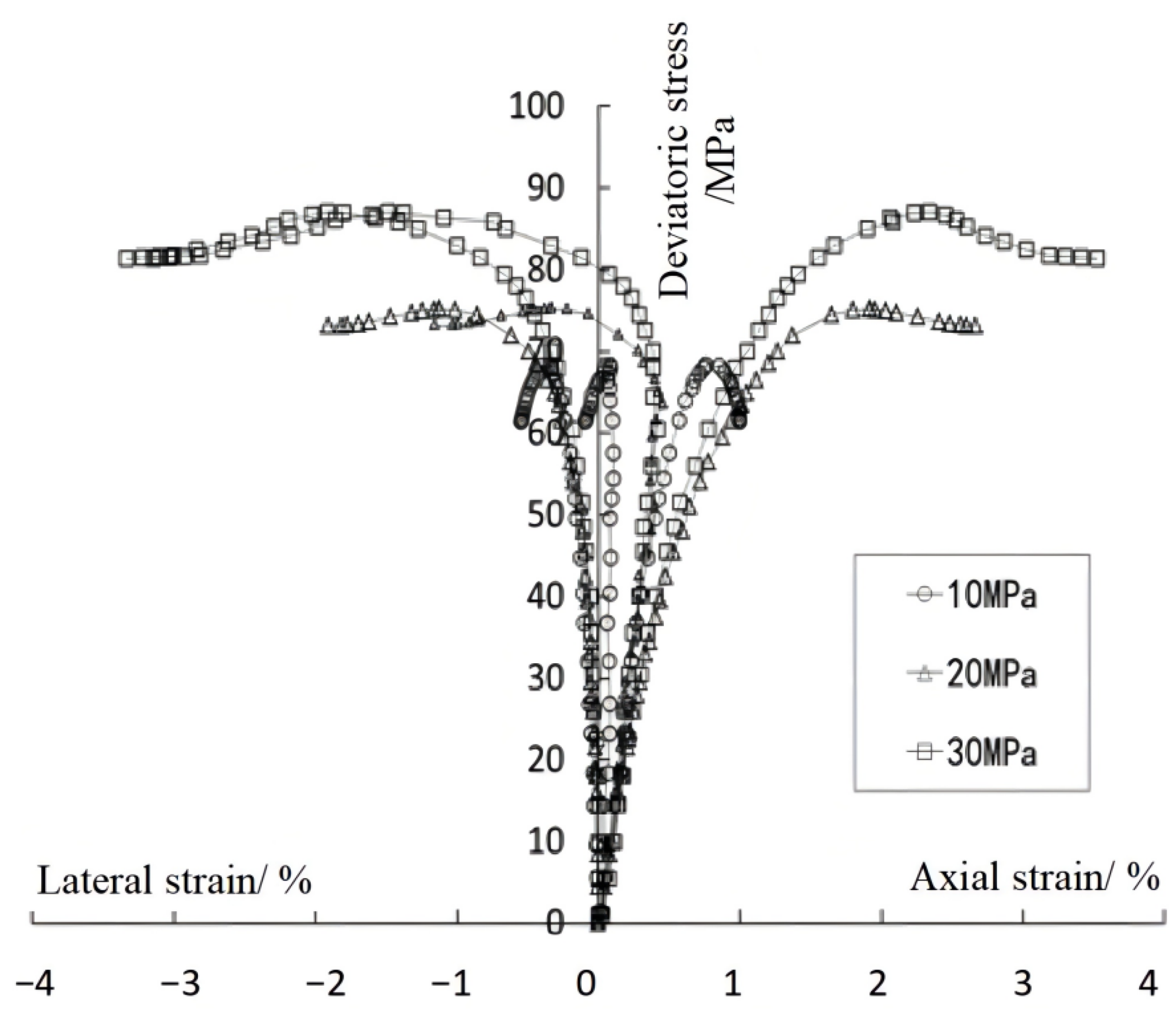
2.2. Conventional Triaxial Compression Test

The conventional triaxial compression test results show that the deformation behavior of the mudstone rock samples under different confining pressures is similar, and the homogeneity is good (Figure 3). The samples also show brittle failure characteristics under low confining pressure and large plastic compression and lateral expansion under high confining pressure.
When the confining pressure is low, the plastic deformation is small before the peak stress, and the plastic hardening is not obvious. After the peak stress, the stress begins to decrease, and the rock sample shows rapid brittle failure. With the increase in confining pressure, the peak stress also increases. Before the peak stress, the damage evolution is slow, plastic deformation is dominant, and the plastic hardening phenomenon is obvious (Table 1). After the peak stress, the damage evolution gradually dominates, and the stress shows a downward trend. Frictional sliding between the cracks intensifies, and plastic deformation continues to grow. Meanwhile, the internal cracks of the rock sample begin to penetrate, and the volume gradually expands at the macro scale, and the stress reaches the residual strength, which is carried by the friction force of the internal crack surface.

2.3. Damage Evolution

The damage variable can quantitatively describe the deterioration degree of rock material properties [21]. Based on the existing damage variable calculation method [22], the damage variable of mudstone is obtained using a stress–strain curve (Figure 4). According to the inflection point E after the peak stress, the damage variable calculation is divided into two parts: before the inflection point E, the elastic modulus without damage is obtained based on the straight line ‘OK’, and thus, the damage variable at point I is as follows:
ε e I = σ I E
ω I = 1 ε e I ε I
where ω is the damage variable, ε is the total strain, ε e is the elastic strain, and σ is the axial stress.
However, this method has some limitations. The calculated damage variable rapidly increases after the peak strength and exponentially increases in the residual strength stage. However, acoustic emission technology is used to monitor the whole process of the triaxial test [23], and it was found that an acoustic emission signal is not active after rock failure. Therefore, the above method is improved, and the damage variable is calculated according to the above method before the inflection point E in the post-peak stage. After the inflection point E, the damage variable of point F is as follows:
ω F = ω E + ( 1 σ F σ E )
The damage evolution variation of mudstone under different confining pressures is obtained (Figure 5):
(1) Elastic damage stage ‘OA’ (corresponding to the initial straight section of the stress–strain curve in Figure 4): mudstone is in the elastic stage, showing small damage and slow development;
(2) Plastic-dominated elastoplastic damage coupling stage ‘AB’ (corresponding to the curve section before point E of the stress–strain curve in Figure 4): mudstone presents plastic deformation characteristics, and damage occurs and rapidly accumulates;
(3) Damage-dominated elastoplastic damage coupling stage ‘BC’ (corresponding to the curve segment after point E of the stress–strain curve in Figure 4): the damage accumulates and controls, and the stress gradually decreases.

3. Elastoplastic Damage Coupling Mechanical Model

3.1. Elastoplastic Damage Coupling

Assuming that mudstone is a small strain and isotropic material, the total strain increment ε ˙ is composed of an elastic strain increment ε ˙ e and a plastic strain increment ε ˙ p :
ε ˙ = ε ˙ e + ε ˙ p
Under the condition of an isothermal and static load, the Helmhotz free energy φ is composed of elastic free energy φ e and plastic free energy φ p [24]:
φ ( ε e , γ p , ω ) = φ e ( ε e , ω ) + φ p ( γ p , ω )
where ε e is the second-order elastic strain tensor, and γ p and ω are the plastic internal variable and the damage internal variable, respectively. Based on the Clausius–Duhan inequality of thermodynamics, the entropy increment η ˙ is as follows:
η ˙ = σ : ε ˙ φ ˙ 0
where σ is the second-order stress tensor. Bringing d φ into Equation (6):
( σ φ e ε e ) : ε ˙ e + ( σ : ε ˙ p φ p γ p γ p ˙ ) φ ω ω ˙ 0
The total equation of the stress–strain relation is obtained:
σ = φ e ε e
The damage driving forces related to plasticity and damage are:
K = φ p γ p
Y = φ ω
It is assumed that the plastic potential function g p and the damage potential function g ω are both functions of the damage driving force and the damage variable, and the plastic strain ε p is closely related to stress, so the plastic potential function g p is also a function of stress:
g p = g p ( σ ,   K ; ω )
g ω = g ω ( Y ; ω )
The increment of the plastic internal variable γ p ˙   and the increment of the damage internal variable ω ˙ are as follows:
γ p ˙ = f ( ε ˙ p ) ,   ε ˙ p = λ ˙ g p σ
ω ˙ = μ ˙ g ω Y
where λ ˙ and μ ˙ are a non-negative plastic factor and a damage factor, respectively. Combining the consistency conditions of the yield surface equation f p = f p ( σ , K ; ω ) and damage evolution equation f ω = f ω ( Y ; ω ) , it can be found that:
f ˙ p = f p σ : σ ˙ + f p K : K ˙ + f p ω ω ˙ = 0
f ˙ ω = f ω Y : Y ˙ + f ω ω   ω ˙ = 0
The plastic internal variable γ p and damage internal variable ω can be determined, and the elastoplastic damage coupling calculation of mudstone can be realized.

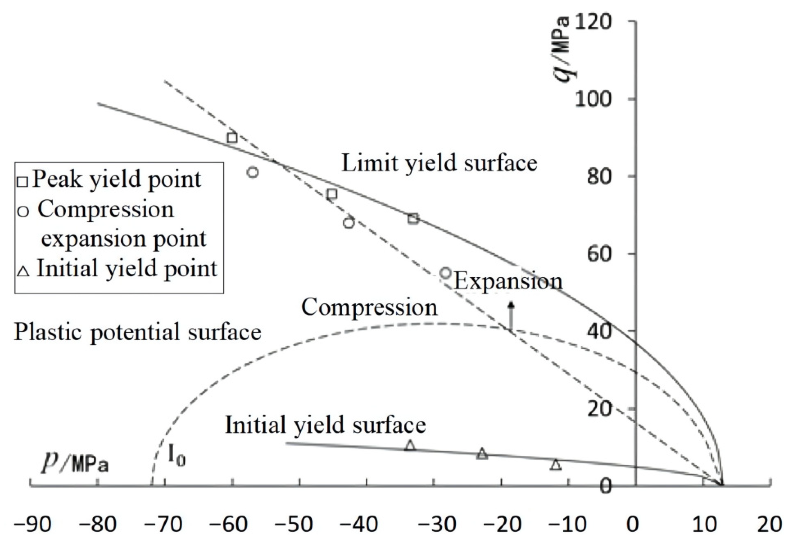
3.2. Construction of the Mechanical Model

Based on the existing research [25], the elastic free energy φ e and plastic free energy φ p of Helmholtz are, respectively:
φ e = 1 2 ε e : D ( ω ) : ε e
φ p = ( 1 ω ) A [ γ p b ( 1 α p 0 ) l n γ p + b b ]
where D ( ω ) is the fourth-order elastic stiffness tensor after material damage, and the bulk modulus K and shear modulus G can be expressed as the function of the damage variable ω [26]:
K ( ω ) = ( 1 ω ) K 0   ,   G ( ω ) = ( 1 ω ) G 0
where K 0 and G 0 are the volume modulus and shear modulus of the material without damage, respectively. The damage driving force is obtained:
Y = φ ω = Y e + Y p
Y e = 1 2 ε e : D ( ω ) : ε e
Y p = A [ γ p b ( 1 α p 0 ) l n γ p + b b ]
where D ( ω ) = D ( ω ) / ω . Based on the damage evolution of mudstone, the damage evolution equation of mudstone is defined as [27]:
f ω = Y e + Y p Y p + 1 ( m ω + Y 0 ) = 0
where m is the damage parameter, which is related to the damage evolution, and Y 0 is the damage threshold, which is related to the damage starting time. This paper takes Y 0 = 0 , which means deformation and damage simultaneously occur.
When f ω < 0 , there is no damage. When f ω = 0 , damage occurs, and the damage evolution satisfies the consistency condition:
f ω ˙ = Y e ε e : ε e ˙ + f ω Y p Y p γ p γ p ˙ + f ω ω ω ˙ = 0
The average stress p and deviatoric stress q are used to describe the limit yield state. The failure of mudstone conforms to non-linear yield characteristics (Figure 6), and the non-linear plastic yield function corresponding to mudstone is obtained:
f p = q 2 + A α p ( p C 0 ) p 0 = 0 p = σ k k 3   ,   q = 3 J 2 J 2 = 1 2 S i j S i j   ,   S i j = σ i j σ k k 3 δ i j }  
where A is the internal friction coefficient, C 0 is the cohesive coefficient, and α p is the hardening function, which can be expressed as a power function monotonically increasing with the plastic internal variables γ p :
α p = ( 1 ω ) [ α p 0 ( α p 0 1 ) γ p b + γ p ] γ p = 2 3 e i j p e i j p   ,     e i j p = ε i j p ε k k p 3 δ i j }
where α p is the initial value of the hardening function, and b is the hardening rate parameter. The variation of the yield surface with plastic deformation and damage evolution can be described by α p : before the peak stress, the yield surface expands with the increase in plastic deformation, showing hardening characteristics; after the peak stress, the yield surface decreases with the increase in damage, showing softening characteristics; and when the damage increases to the maximum, the mudstone reaches the residual strength.
In the loading process, when f p < 0 , it is only elastic deformation. When f p = 0 , it presents plastic deformation and satisfies the consistency condition:
f p ˙ = f p σ : σ ˙ + f p α p ( α p ω   ω ˙ + α p γ p γ p ˙ ) = 0
As mudstone shows obvious volume expansion, the associated flow rule is not applicable because it does not consider the energy dissipation during plastic deformation, which expands the expansion of the material. Therefore, the non-associated flow rule is used to calculate the plastic deformation to accurately describe the volume change from compression to expansion. The plastic potential function is expressed as:
g p = q + ( 1 ω ) A η ( p C 0 ) l n ( p C 0 I 0 ) = 0
where the variable I 0 < 0 is the stress state at the intersection of the plastic potential surface and the average stress axis (Figure 6); the plastic potential surface divides the stress space into two regions, corresponding to volume compression and volume expansion, respectively, with g p / p = 0 as the conversion conditions; and η is a descriptive parameter for volume compression and expansion, which means the slope of the boundary line between the compressibility–dilation zones [28].

3.3. Realization of the Mechanical Model

When considering plasticity and damage, the strain increment is:
σ ˙ = D ( ω ) : ( ε ˙ ε ˙ p ) + D ( ω ) : ε e   ω ˙
In the loading process, the mudstone presents two stages of elastic damage coupling and elastoplastic damage coupling:
The elastic damage stage is ε ˙ p = 0 ,   d ω > 0 . The damage increment can be obtained using Formula (24):
ω ˙ = f ω Y e Y e ε e : ε ˙ = ε e : C ( ω ) : ε ˙
It can be solved using the simultaneous Formulas (29) and (30):
σ ˙ = [ D ( ω ) ( D ( ω ) : ε e ) ( ε e : D ( ω ) ) ] : ε ˙ = D e q ( ω ) : ε ˙
D e q ( ω ) is the fourth-order equivalent stiffness tensor.
The elastoplastic damage stage ε ˙ p 0 ,   ω ˙ > 0 , plastic internal variables and damage internal variables need to be solved using the simultaneous Formulas (24) and (27):
f p σ : D ( ω ) : ε ˙ + ( f p σ : D ( ω ) : ε e + f p ω ) ω ˙ H λ ˙ = 0
ε e : D ( ω ) : ε ˙ + [ D ( ω ) : ε e : g p σ + f ω γ p ] λ ˙ m ω ˙ = 0
H = f p σ : D ( ω ) : g p σ f p γ p
Thus, the damage evolution and stress–strain relationship of mudstone under elastoplastic damage coupling conditions are obtained.

4. Simulation Verification of the Model

4.1. Mechanical Model Parameters

The elastoplastic damage coupling mechanical model contains eight parameters, which are the sum of two elastic parameters E and ν , five plastic parameters A, C 0 ,   α p 0 ,   b ,   η , and one damage parameter m. Among them, E and ν are the elastic modulus and the Poisson’ s ratio, which can be obtained according to the slope of the linear elastic section, the ratio of the axial strain ε 1   and the lateral strain ε 3 of the stress–strain curve, respectively. A and C 0 can be determined using the intercept and slope of the average stress p and deviatoric stress q curve under the limit yield stress state. α p 0 can be determined using the average stress p and deviatoric stress q curve of the initial yield surface. b can be determined using the hardening function α p   and plastic internal variable γ p relationship. η can be determined using the stress state of the transformation from volumetric compression to expansion [29]. The damage parameter m can be determined using the damage evolution curve.
The sensitivity analysis of some parameters of the model was carried out, including the plastic parameters b and η and damage parameter m. The parameter b has effects on the hardening rate, plastic deformation and damage evolution (Figure 7). Before the peak stress, the smaller the value b, the more obvious the plastic hardening, the peak stress increases, and the plastic deformation increases. After the peak stress, the smaller the value of b and the faster the stress drop, indicating the greater the post-peak damage. When the value of b is close to 0, there is no plastic hardening stage before the peak, and the stress–strain curve is linear; damage leads to the decrease in post-peak stress, and the elastoplastic damage coupling model degenerates into the elastic damage model. The parameter η is closely related to the compression–expansion conversion of material volume deformation (Figure 8). η has a small influence on peak stress and post-peak residual strength. The larger the value of η, the earlier the compression–expansion inflection point will appear, and the expansion effect of the volume deformation is more obvious.
The parameter m is related to damage evolution (Figure 9). It has little effect on the pre-peak deformation. With the decrease in m, the peak stress decreases, and the damage variable at the peak point increases. The influence of m on the post-peak deformation is obvious. The smaller the value of m, the faster the stress drop rate after the peak, the more obvious the deformation under the same stress, the lower the post-peak residual strength and the faster the growth rate of the damage variable, resulting in greater damage. When m is approaching infinity, the stress–strain curve has no post-peak softening stage, and the model degenerates into an elastoplastic constitutive model. When m approaches infinity and b approaches 0, the model degenerates into an ideal elastoplastic model.

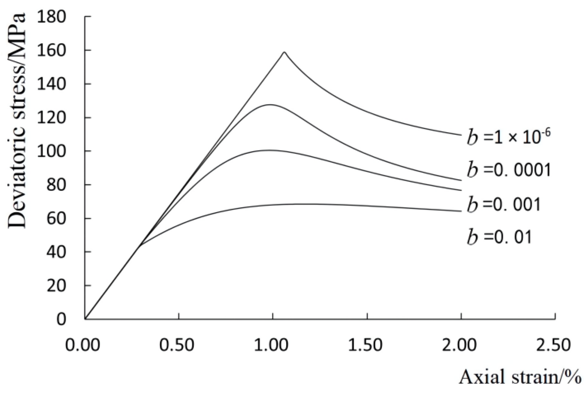
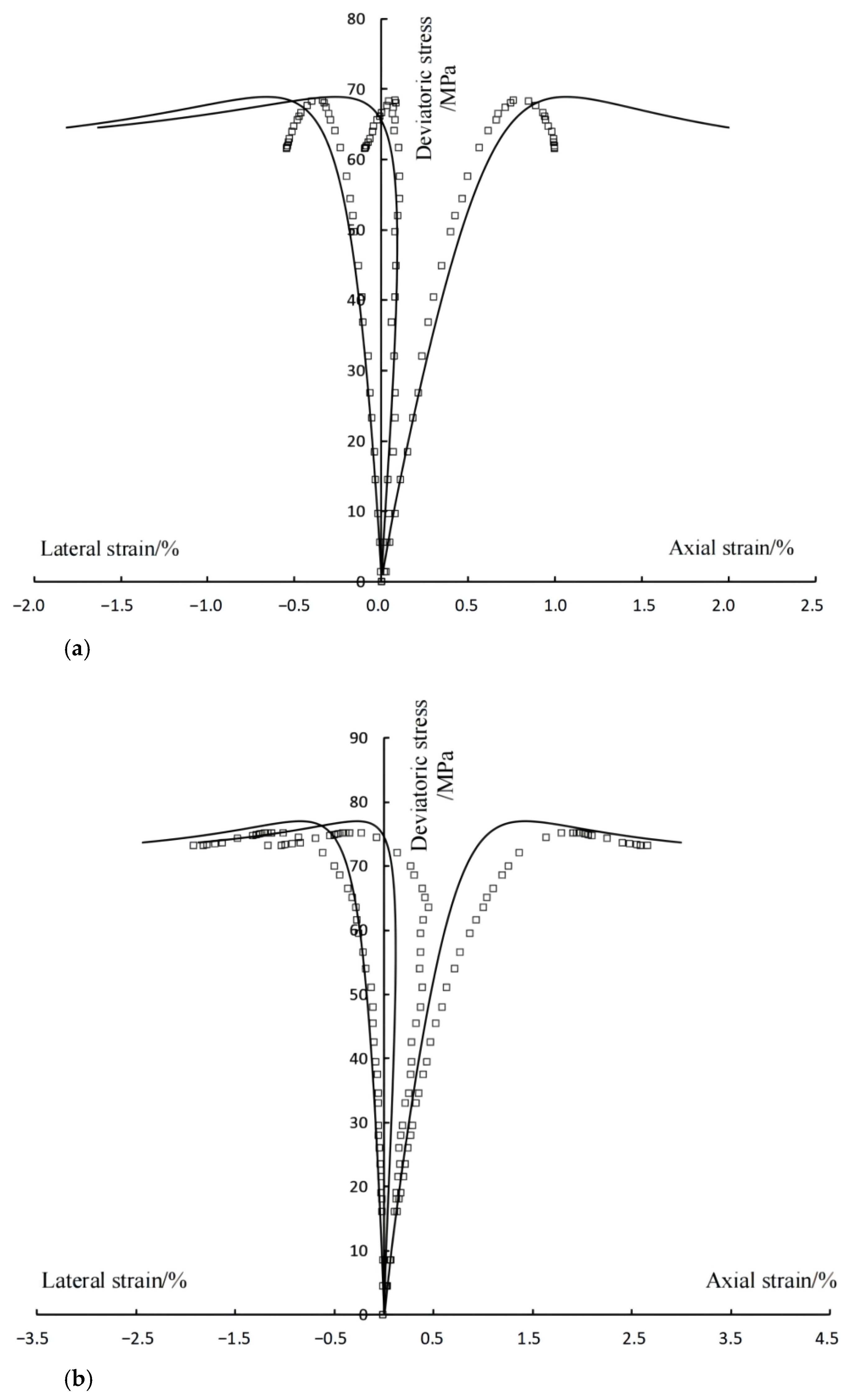
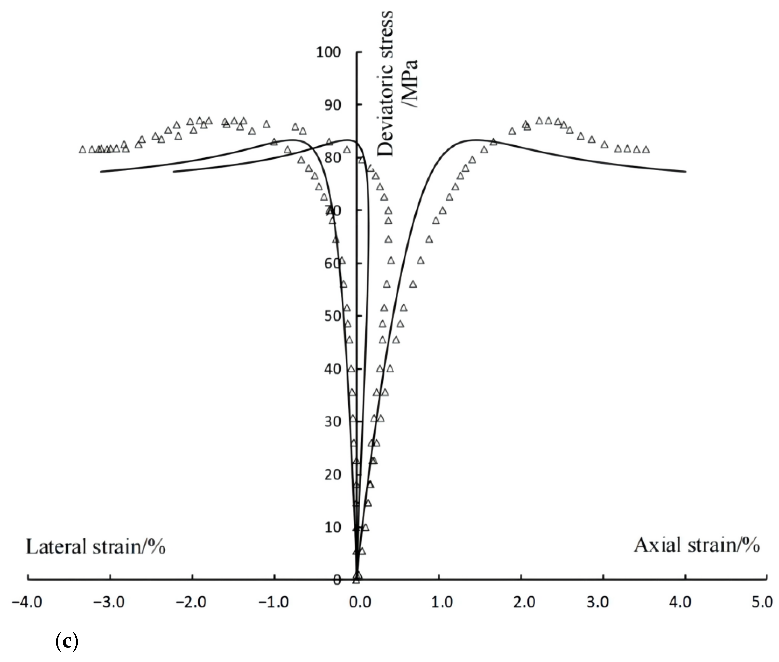
4.2. Verification of the Constitutive Equation

Based on the above elastoplastic damage coupling mechanical parameters (Table 2) and the secondary development of the ABAQUS software, a UMAT subroutine was written for the simulation verification. The axial, lateral and volumetric stress–strain curves under different confining pressures were simulated (Figure 10). This mechanical model can better describe the mechanical properties of mudstone, such as volumetric compression–expansion conversion, plastic hardening, damage softening and residual strength. The simulation results are in good agreement with the experimental results. Therefore, it is considered that the above elastoplastic damage coupling mechanical analysis is reasonable, and the proposed mechanical model can describe the elastoplastic damage mechanical characteristics of mudstone observed in the test.

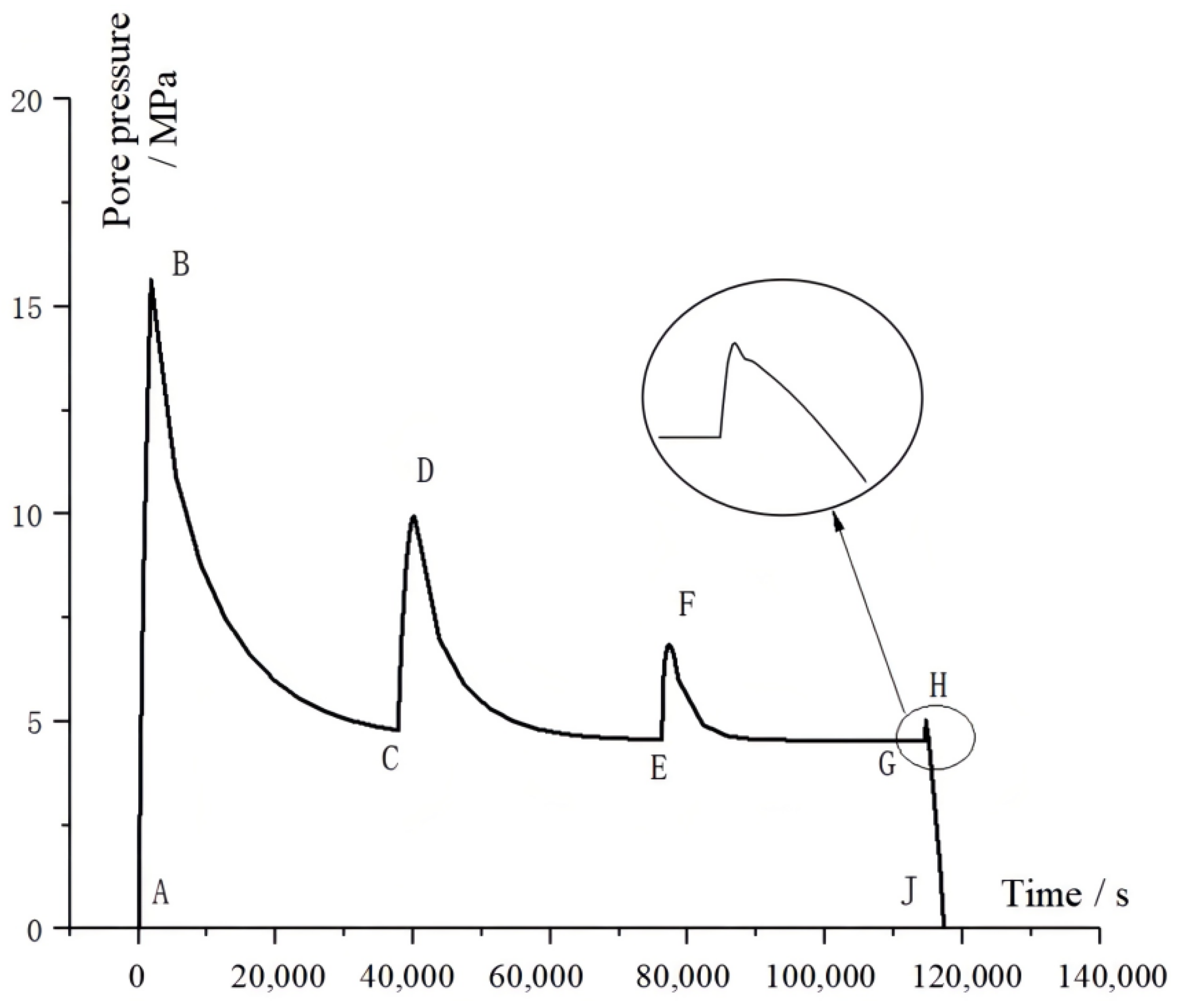
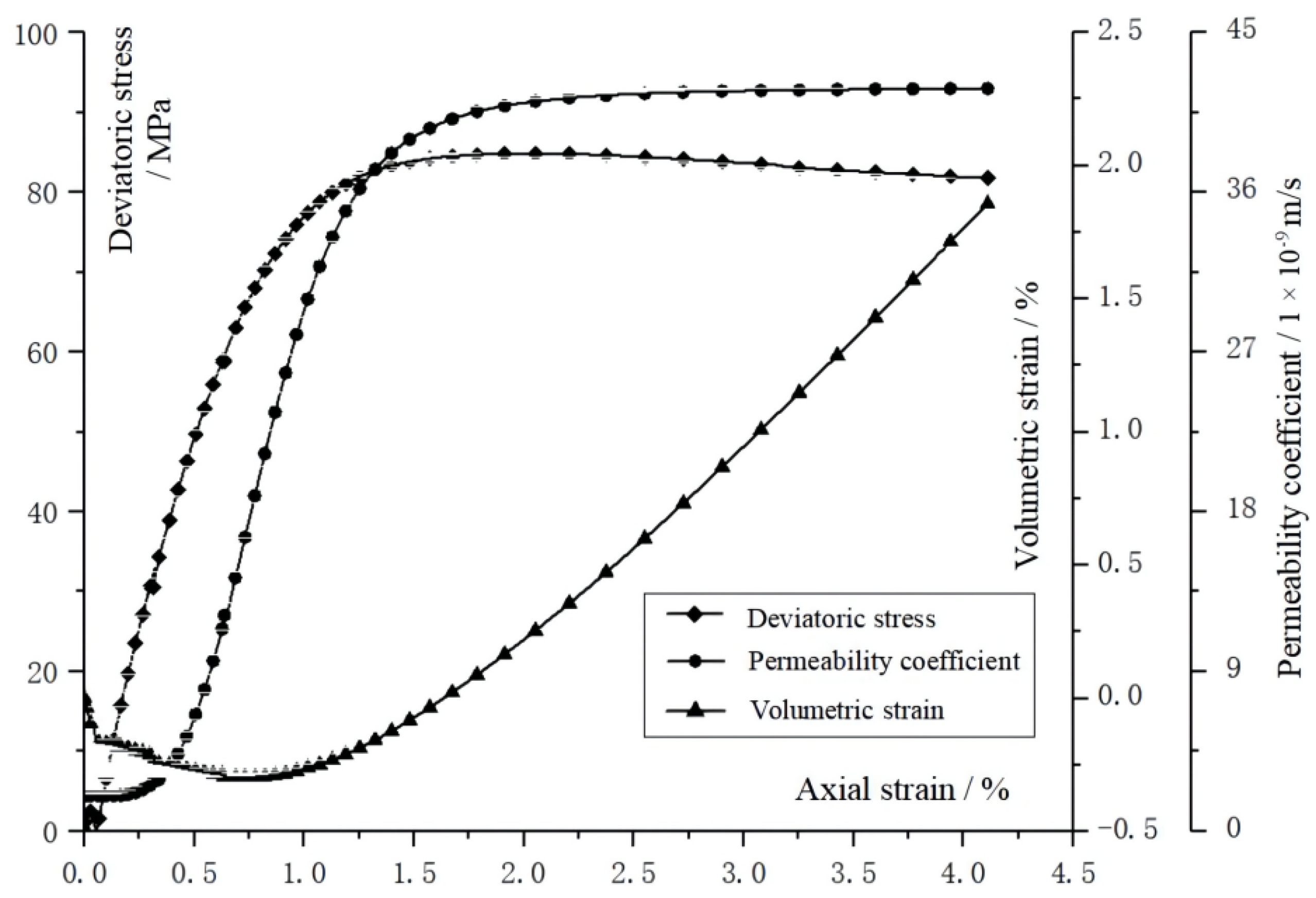
5. Simulation Analysis of Seepage–Stress Coupling

5.1. Permeability Evolution Model

The permeability evolution model reflects the coupling relationship between the stress–strain field and the seepage field. Through the permeability test of mudstone, Yu [30] obtained the evolution relationship between the stress–strain state, volume strain and permeability under pressure. In the process of whole stress–strain, the change in permeability is a complex process that first slightly decreases, then slowly increases, then suddenly increases and finally tends to be stable. Zhang [31] analyzed the process combined with volume strain and divided the whole process into five stages. However, in fact, the critical point of each stage is difficult to accurately define. From a physical point of view, the permeability evolution is related to the closure, development and penetration of internal pores and fissures, and the change in pores and fissures is closely related to the damage and plastic deformation of materials. Considering that the change in permeability in the compression stage of mudstone is much smaller than that in the expansion stage, and the latter stage is mainly used in oil and gas exploitation engineering, this paper defines the evolution of permeability as a function of the damage variable and simplifies it into two stages: D = 0 and D 0 . Further, referring to the research results [32,33], the permeability evolution model is defined as:
k = { k 0 ,     D = 0   k 0 [ 1 + ξ ( 1 e n D ) 2 ]   , D 0
where k 0 is the initial permeability coefficient, and n and ξ are the model parameters. They can be obtained by fitting the permeability coefficient curve. ξ is the magnitude increasing coefficient, which can describe the sharp increase in the permeability coefficient in the damage–fracture process of mudstone.

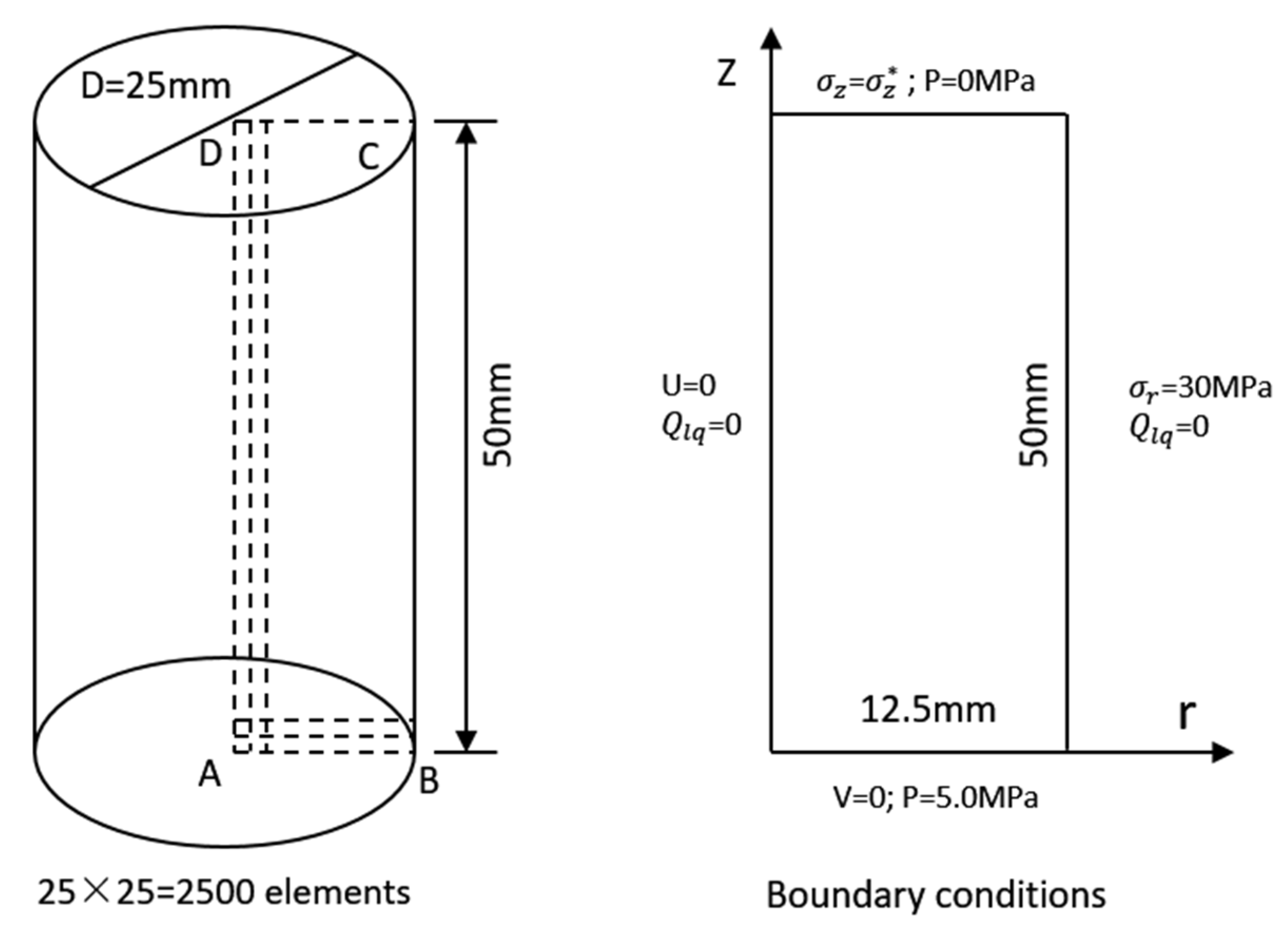
5.2. Numerical Simulation of Seepage–Stress Coupling

The permeability evolution model is written as a USFLD subroutine of ABAQUS. Based on Soils (the fluid–solid coupling analysis step of ABAQUS), UMAT (the elastoplastic damage coupling mechanical model subroutine) and USFLD (the permeability evolution model subroutine), the solution of seepage–stress coupling is realized [34].
Taking the mudstone sample of the indoor triaxial permeability test as the research object, an axisymmetric finite element model was established as shown in Figure 11. The bottom and the left boundary are fixed in the y direction and the x direction, respectively. Firstly, 30 MPa confining pressure is applied. Then, 5 MPa pore pressure is applied at the bottom, and the water is drained through the top. Finally, the deviatoric stress is applied in stages using the top displacement control.
The initial permeability coefficient of mudstone is 1 × 10⁻⁹ m/s. Based on the simulation results, the pore pressure evolution curve (Figure 12) and the permeability coefficient evolution curve (Figure 13) of the sample near the bottom were obtained. In Figure 12, the curve AB shows the stage of applying confining pressure, curve BC shows the pore pressure evolution stage after the initial pore pressure is applied, curves CD, EF and GJ show the stages with different axial compression, and curves DE and FG show the pore pressure evolution stages after stopping axial compression loading. Comparing the three pore pressure evolution stages, it can be seen that after applying axial pressure, the pore pressure dissipation rate significantly increases with the gradual increase in the permeability coefficient. As the axial pressure increases, the volume deformation of the rock sample changes from compression to expansion, the internal cracks rapidly develop, the pores rapidly penetrate, and the pore pressure in the curve GJ rapidly decreases. As shown in Figure 13, before the lowest point of the volumetric strain curve, that is, the compression–expansion critical point, the internal deformation of the rock sample is mainly compression, and the closure of the pores and fissures, plastic deformation and damage evolution simultaneously occur under compressive stress, so the permeability coefficient slightly increases with the axial compression loading. After the critical point, the plastic deformation and damage rapidly increase, and the pores and fissures inside the rock sample rapidly develop and connect, resulting in the sharp increase in the permeability coefficient and rapidly reaching the peak.

6. Conclusions

On the basis of the triaxial compression tests of mudstone in high buried depth reservoirs under different confining pressures, the damage evolution and elastoplastic damage coupling mechanical characteristics were discussed, and the elastoplastic damage coupling mechanical model was proposed. The main conclusions are as follows:
(1) The integrity of mudstone is good. Under different confining pressures, the plastic hardening and damage softening characteristics are obvious. Thus, the damage evolution of mudstone is characterized by three stages: an elastic damage stage, a plastic-dominated elastoplastic damage coupling stage and a damage-dominated elastoplastic damage coupling stage.
(2) Elastic free energy and plastic free energy are expressed by plastic internal variables and damage internal variables. On the basis of considering the elastic damage coupling and elastoplastic damage coupling in the loading process, the elastoplastic damage coupling mechanical model of mudstone is proposed.
(3) On the basis of determining the mechanical parameters of the model, the simulation study on the elastoplastic damage coupling mechanical characteristics of mudstone in high buried depth reservoir was carried out. The simulation results are in good agreement with the experimental results, which can better reflect the mechanical properties of mudstone such as volume compression–expansion conversion, plastic hardening, damage softening and residual strength.
(4) The secondary development was carried out in ABAQUS, and the constitutive model and permeability evolution model were written as UMAT and USFLD subroutines, respectively, and then the seepage–stress coupling numerical simulation was carried out. The simulation results show that with the loading of axial deviatoric stress, the evolution of the permeability coefficient undergoes slow increase, rapid increase and stabilization stages.

Author Contributions

Data curation, W.J. and Y.Z. (Yu Zhang); Formal analysis, W.J. and S.M.; Methodology, W.J. and Y.Z. (Yanan Zhao); Resources, S.M. and Y.Z. (Yanan Zhao); Supervision, S.M. and Y.Z. (Yanan Zhao); Writing—original draft, W.J. and Y.Z. (Yu Zhang); Writing—review & editing, W.J. and Y.Z. (Yu Zhang). All authors have read and agreed to the published version of the manuscript.

Funding

This research was funded by China Natural Science Foundation grant number 51890914 and 52179119, Natural Science Foundation of Shandong Province grant number ZR2019MEE001, and Open Research Fund of Hunan Provincial Key Laboratory of Hydropower Development Key Technology grant number PKLHD202001.

Data Availability Statement

All data and models generated or used during the study appear in the submitted article.

Acknowledgments

The authors wish to thank the three reviewers and the editor for their kind advice, which has significantly enhanced the soundness of this paper.

Conflicts of Interest

The authors declare no conflict of interest.

References

  1. Corkuma, A.G.; Martinb, C.D. The mechanical behaviour of weak mudstone (Opalinus Clay) at low stresses. Int. J. Rock Mech. Min. 2007, 44, 196–209. [Google Scholar] [CrossRef]
  2. Nooraiepour, M.; Haile, B.G.; Hellevang, H. Compaction and mechanical strength of Middle Miocene mudstones in the Norwegian North Sea-The major seal for the Skade CO2 storage reservoir. Int. J. Greenh. Gas Control 2017, 67, 49–59. [Google Scholar] [CrossRef]
  3. Wang, Q.; Hu, X.L.; Xu, C.; Zhou, C.; He, C.C.; Ying, C.Y. Time-dependent behavior of saturated silty mudstone under different confining pressures. Bull. Eng. Geol. Environ. 2020, 79, 2621–2634. [Google Scholar] [CrossRef]
  4. Chen, Z.F.; Li, X.Y.; Wang, W.; Lu, K.Q.; Zhu, W.P. Theoretical analysis of casing collapse in locally expansive mudstone. J. Pet. Sci. Eng. 2021, 203, 108643. [Google Scholar] [CrossRef]
  5. Chen, M.; Zang, C.W.; Ding, Z.W.; Zhou, G.L.; Jiang, B.Y.; Zhang, G.C.; Zhang, C.P. Effects of confining pressure on deformation failure behavior of jointed rock. J. Cent. South Univ. 2022, 29, 1305–1319. [Google Scholar] [CrossRef]
  6. Conil, N.; Djeran-Maigre, I.; Cabrillac, R.; Su, K. Thermodynamics modelling of plasticity and damage of argillite. CR Mec. 2004, 332, 841–848. [Google Scholar] [CrossRef]
  7. Zhou, C.Y.; Zhu, F.X. An elasto-plastic damage constitutive model with double yield surfaces for saturated soft rock. Int. J. Rock Mech. Min. 2010, 47, 385–395. [Google Scholar] [CrossRef]
  8. Zhou, X.P. Dynamic damage constitutive relation of mesoscopic heterogenous brittle rock under rotation of principal stress axes. Theor. Appl. Fract. Mech. 2010, 54, 110–116. [Google Scholar] [CrossRef]
  9. Zhao, G.M.; Xie, L.X.; Meng, X.R. A damage-based constitutive model for rock under impacting load. Int. J. Min. Sci. Technol. 2014, 24, 505–511. [Google Scholar] [CrossRef]
  10. Unteregger, D.; Fuchs, B.; Hofstetter, G. A damage plasticity model for different types of intact rock. Int. J. Rock Mech. Min. 2015, 80, 402–411. [Google Scholar] [CrossRef]
  11. Liu, Y.; Dai, F. A damage constitutive model for intermittent jointed rocks under cyclic uniaxial compressio. Int. J. Rock Mech. Min. 2018, 103, 289–301. [Google Scholar] [CrossRef]
  12. Wu, G.J.; Chen, W.Z.; Rong, C.; Jia, S.P.; Dai, Y.H. Elastoplastic damage evolution constitutive model of saturated rock with respect to volumetric strain in rock and its engineering application. Tunn. Undergr. Space Technol. 2020, 97, 103284. [Google Scholar] [CrossRef]
  13. Zhang, X.; Lin, H.; Wang, Y.X.; Zhao, Y.L. Creep damage model of rock mass under multi-level creep load based on spatio-temporal evolution of deformation modulus. Arch. Civ. Mech. Eng. 2021, 21, 71. [Google Scholar] [CrossRef]
  14. Wu, L.Y.; Wang, Z.F.; Ma, D.; Zhang, J.W.; Wu, G.M.; Wen, S.; Zha, M.L.; Wu, L.Z. A Continuous Damage Statistical Constitutive Model for Sandstone and Mudstone Based on Triaxial Compression Tests. Rock Mech. Rock Eng. 2022, 55, 4963–4978. [Google Scholar] [CrossRef]
  15. Monfared, M.; Sulem, J.; Delage, P.; Mohajerani, M. A laboratory investigation on thermal properties of the opalinus claystone. Rock Mech. Rock Eng. 2011, 44, 735–747. [Google Scholar] [CrossRef]
  16. Ge, Z.L.; Sun, Q.; Li, W.P. Temperature and Pressure Effect on Permeability of Chinese Sandstone: A Review. Acta Geodyn. Geomater. 2018, 15, 289–296. [Google Scholar] [CrossRef] [Green Version]
  17. Chen, L.; Wang, C.P.; Liu, J.F.; Liu, Y.M.; Liu, J.; Su, R.; Wang, J. A damage-mechanism-based creep model considering temperature effect in granit. Mech. Res. Commun. 2014, 5, 76–82. [Google Scholar] [CrossRef]
  18. Wang, X.L.; Zhang, H.J.; Qian, L.; Yao, T.Z.; Mo, Z.G.; He, J.H.; Zhang, R. Nonlinear statistical damage constitutive model of granite based on the energy dissipation ratio. Sci. Rep. 2022, 12, 5460. [Google Scholar] [CrossRef]
  19. Wang, J.B.; Zhang, Q.; Song, Z.P.; Zhang, Y.W.; Liu, X.R. Mechanical properties and damage constitutive model for uniaxial compression of salt rock at different loading rates. Int. J. Damage Mech. 2021, 30, 739–763. [Google Scholar] [CrossRef]
  20. He, M.M.; Li, N.; Zhu, C.H.; Chen, Y.S.; Wu, H. Experimental investigation and damage modeling of salt rock subjected to fatigue loading. Int. J. Rock Mech. Min. 2019, 114, 17–23. [Google Scholar] [CrossRef]
  21. Yu, S.W.; Feng, X.Q. Damage Mechanics; Tsinghua University Press: Beijing, China, 1997. [Google Scholar]
  22. Zhou, J.W.; Yang, X.G.; Fu, W.X.; Xu, J.; Li, H.T.; Zhou, H.W.; Liu, J. Experimental test and fracture damage mechanical characteristics of brittle rock under uniaxial cyclic loading and unloading conditions. Chin. J. Rock Mech. Eng. 2010, 29, 1172–1183. (In Chinese) [Google Scholar]
  23. Chen, L.; Liu, J.F.; Wang, C.P.; Wang, X.Y.; Su, R.; Wang, J.F.; Shao, J. Elastoplastic damage model of Beishan deep granite. Chin. J. Rock Mech. Eng. 2013, 32, 289–298. (In Chinese) [Google Scholar]
  24. Qi, H.; Li, Y.G.; Lu, X.L. A practical elastic plastic damage constitutive model Based on energy. Eng. Mech. 2013, 30, 172–180. (In Chinese) [Google Scholar]
  25. Li, Z.; Liu, S.G.; Yu, J.X.; Hu, M.M. Study on Mechanical Model of Chlorite Schist Considering Elastoplastic Damage Coupling. Chin. J. Undergr. Space Eng. 2017, 13, 101–107. (In Chinese) [Google Scholar]
  26. Pensee, V.; Kondo, D.; Dormieux, L. Micromechanical Analysis of Anisotropic Damage in Brittle Materials. J. Eng. Mech. 2007, 128, 889–897. [Google Scholar] [CrossRef]
  27. Shao, J.F.; Jia, Y.; Kondo, D.; Chiarelli, A.S. A coupled elastoplastic damage model for semi-brittle materials and extension to unsaturated conditions. Mech Mater. 2006, 38, 218–232. [Google Scholar] [CrossRef]
  28. Shao, J.F.; Zhu, Q.Z.; Su, K. Modeling of creep in rock materials in terms of material degradation. Comput. Geotech. 2003, 30, 549–555. [Google Scholar] [CrossRef]
  29. Zhang, Y.; Zhang, X.D.; Shao, J.F.; Jia, Y.; Wang, Y.L. Elastoplastic modelling the creep behaviour of cataclastic rock under multi-stage deviatoric stress. Eur. J. Environ. Civ. Eng. 2018, 22, 650–665. [Google Scholar] [CrossRef]
  30. Yu, H.D. Study on Long Term Hydro-Mechanical Coupled Behavior of Belgium Boom Clay; Institute of Rock and Soil Mechanics, Chinese Academy of Sciences: Wuhan, China, 2010. (In Chinese) [Google Scholar]
  31. Zhang, L.W. A Research of Boom Clay Elastic-Plastic Constitutive Model Considering the Coupling Effects of Stress and Seepage; School of Urban Construction, Yangtze University: Hubei, China, 2014. (In Chinese) [Google Scholar]
  32. Jia, S.P.; Gao, M.; Gong, J.; Chen, W.Z.; Yu, H.D. Permeability Evolution Model for Clay Stone with High Porosity and Low Permeability in Coupled Hydro-mechanical Condition. J. Basic Sci. Eng. 2015, 23, 1221–1234. (In Chinese) [Google Scholar]
  33. Yang, H.; Jia, Y.; Xie, S.Y.; Shao, J.F. An Experimental and Numerical Investigation of the Mechanical Behaviour of a Concrete and of its Permeability Under Deviatoric Loading. Transp. Porous Med. 2014, 102, 427–454. [Google Scholar] [CrossRef]
  34. Jia, S.P.; Gao, M.; Yu, H.D.; Gong, J. A Coupled Damage-Permeability Model of Clay Stone with High Porosity and Low Permeability and Its Numerical Implementation. J. Cent. South Univ. Sci. Technol. 2016, 47, 558–568. (In Chinese) [Google Scholar]
Figure 1. Typical deep oil reservoir mudstone samples.
Sustainability 14 13507 g001
Figure 2. The rock automatic triaxial rheological servo instrument. (a) Triaxial pressure cell. (b) Strain measurement. (c) Data acquisition.
Sustainability 14 13507 g002
Figure 3. Stress–strain cures of mudstone under triaxial compression test.
Sustainability 14 13507 g003
Figure 4. Schematic diagram of damage variable calculation.
Sustainability 14 13507 g004
Figure 5. Damage evolution curve of mudstone.
Sustainability 14 13507 g005
Figure 6. Initial yield surface, limit yield surface and compression expansion transformation.
Sustainability 14 13507 g006
Figure 7. Sensitivity analysis of parameter b .
Sustainability 14 13507 g007
Figure 8. Sensitivity analysis of parameter η .
Sustainability 14 13507 g008
Figure 9. Sensitivity analysis of parameter m . (a) Effects of parameter m on stress–strain curves. (b) Effects of parameter m on damage variables.
Sustainability 14 13507 g009
Figure 10. Simulation results of triaxial compression tests under different confining pressures. (a) Confining pressure = 10 MPa. (b) Confining pressure = 20 MPa. (c) Confining pressure = 30 MPa.
Sustainability 14 13507 g010aSustainability 14 13507 g010b
Figure 11. Finite element analysis model in ABAQUS.
Sustainability 14 13507 g011
Figure 12. Pore pressure–time evolution curve.
Sustainability 14 13507 g012
Figure 13. Evolution curve of permeability coefficient.
Sustainability 14 13507 g013
Table 1. Mechanical parameters of mudstone under triaxial compression.
Confining Pressure
/MPa
Elastic Modulus
/GPa
Poisson RatioPeak Strength
/MPa
Residual Strength
/MPa
1012.460.28169.1161.48
2013.780.38375.4973.12
3015.830.37487.2881.43
Table 2. Mechanical parameters of elastoplastic damage model.
Parameter TypeSymbols/UnitsParameter Value
Elastic parameter E /MPa14,020
v 0.346
Plastic parameter A 180
C 0 /MPa13.0
α p 0 0.018
b0.0025
η−0.85
Damage parameterm2.75
Publisher’s Note: MDPI stays neutral with regard to jurisdictional claims in published maps and institutional affiliations.

