Article

A Torque-Compensated Fault-Tolerant Control Method for Electric Vehicle Traction Motor with Short-Circuit Fault

College of Information Science and Technology, Donghua University, Shanghai 201620, China
*
Author to whom correspondence should be addressed.
Sustainability 2022, 14(21), 13853; https://doi.org/10.3390/su142113853
Submission received: 15 July 2022 / Revised: 18 October 2022 / Accepted: 21 October 2022 / Published: 25 October 2022
(This article belongs to the Section Energy Sustainability)

Abstract

:
The development of traditional vehicles which consume fossil carbon-based fuels is constrained by environmental pollution and the energy crisis, and it has become a social consensus to develop electric vehicles with new energy resources and low emissions. The drive system of electric vehicles should be able to reliably operate over a long period. When a short-circuit fault occurs in the driving motor, the current in the winding will increase sharply and threaten driving safety. This paper proposed a short-circuit fault-tolerant control strategy for a dual three-phase permanent magnet synchronous traction motor (DT-PMSTM) which can resolve the problem of short-circuit faults. The current in non-short-circuit fault windings has been reconstructed to offset the interference of the short-circuit current and output a stable torque. Based on the principle of constant composited magnetic motive force (MMF), the dimension-reduced orthogonal transformation matrix was derived. The compensation currents were designed according to the interference effect of the short-circuit current to the normal MMF of the motor. Consequently, the lost torque component caused by the lack of the short-circuit winding was compensated, and the torque pulsation was also reduced. The performance of the topologies with neutral point-isolated mode and neutral point-connected mode were both investigated and compared. The validity of the proposed short-circuit fault-tolerant control strategy was proved by the simulation results.

1. Introduction

The using of fossil fuels in traditional vehicles has two negative influences on the sustainable development of society. Firstly, the massive use of fossil energy will cause energy shortages. Secondly, the exhaust gas emissions of traditional vehicles will cause serious environmental pollution problems. Therefore, new energy vehicles have gained widespread attention due to the advantages of diverse energy sources and environment-friendliness for society. The electric vehicle has the advantages of high energy efficiency, zero-emissions and low noise, so it has become the main research branch of new energy vehicles [1].
The electric drive system, including the motor, is an important part of ensuring that electric vehicles operate in a good state for a long time. The characteristics of the driving motor for electric vehicles include high load capacity, low voltage and high-power output, steady-state output and smooth torque. At present, the drive motor often uses an induction motor or permanent magnet synchronous motor (PMSM). Induction motors have a high starting torque and can withstand a harsher working environment, but their volume and weight are large and their power density is not high. In contrast, PMSMs have obvious advantages in terms of quality, efficiency and power density [2,3], which can reduce vehicle weight and extend the range. Meanwhile, the benefits of multiphase motors are high power output at low voltage, high reliability of phase redundancy and abundant control resources [4,5,6,7].
The safety and reliability of the electric drive system are important for the vehicle. In contrast to a three-phase motor, the multi-phase motor still achieves a normal output capacity even without the help of an additional fault-tolerant circuitry when a fault happens. Most of the operation problems of inverters and motors are caused by open-phase faults. To maintain the magnetic motive force (MMF) as unchanged, researchers have developed two fault-tolerant control methods for open-phase faults. In the first method, the decoupling matrix is the same as that used before the fault occurred, and the hysteresis loop control or bi-directional PI controller is usually used in the control system, which leads to variable switching frequencies or extensive off-line calculations [8,9]. In the second method, a reduced-order decoupling matrix is used after the fault occurs, so that the design process of the controller is simplified. The computation-efficient fault-tolerant control method improves the reliability of the system both statically and dynamically [10]. However, this method cannot address the issue of how to store high-dimensional data efficiently. To achieve both memory and computation efficiency, the control task is divided into two sub-tasks to achieve the maximum average torque and decrease the root-mean-square values of the phase currents [11]. Several different control methods have been proposed and applied to multi-phase motors, such as the robust control, the virtual vector modulation, the genetic algorithm and the model predictive control [12,13,14,15]. In [16], a deadbeat current model predictive control method was proposed for dual-three PMSM, and the duty ratio optimization scheme was used for improving the control accuracy of the current. However, the control strategy cannot fully use the health switch of the faulty bridge arm to improve the operation capability. In [17], an open-switch fault-tolerant control method was used to minimize the stator copper loss, which utilizes the remaining health switch in the faulty bridge arm.
Compared with the open-circuit faults, it is more difficult to control a faulty system and make it operate normally when the short-circuit fault occurs. The main reason is that the current in the short-circuit faulty phase winding of the motor increases sharply. It will cause the overheat or burn-up problems of the motor winding if there is not a suitable fault-tolerant control strategy. However, there are few studies in the literature that focus on the short-circuit fault-tolerant operation problem. In [18], a current fault-tolerant control strategy was presented for multi-phase PMSM when both open-circuit and short-circuit faults are present. However, this method is based on a natural coordinate system and uses a proportional-resonant controller to track time-varying signals, which increases the calculation burden. In [19], an open and short circuit post-fault control method was proposed for the dual three-phase PMSM motor with three-phase (in one set) short-circuit fault windings. In [20], the other four phase windings of the five-phase motor are symmetrical after the short-circuit fault occurs in one winding, so the distribution of the short-circuit compensation currents is also symmetrical and not required for further analysis. However, when the short-circuit fault occurs in one stator winding of the dual three-phase permanent magnet synchronous traction motor (DT-PMSTM), the remainder of the windings are asymmetrical, which could lead to two main problems. One is that the optimizing distribution of the short-circuit compensation currents is difficult, and the other one is that the amplitude difference of the phase currents is large.
In this paper, a new fault-tolerant control method including torque compensation and short-circuit current suppression algorithms was proposed for resolving DT-PMSTM short-circuit faults. The transformation matrix in the α-β coordinate system and dimension-reduced orthogonal transformation matrix were calculated under the one-phase default state of the inverter. Additional currents were injected in the z1-z2 subplane to regulate the amplitude and phase of the currents in the asymmetric windings. Then a reconstructed circular rotating magnetic field was built, and the lost torque caused by phase default was also compensated effectively. According to the spatial structure of the winding, the compensation currents of each phase required for suppressing the interference of the short-circuit current to the output torque were calculated. The torque pulsation generated by the short-circuit current was then suppressed effectively.

2. Topologies of the DT-PMSTM System

DT-PMSTM consists of two sets of Y-connected displacement 30° windings. Its spatial structure can effectively eliminate the 5th, 7th, and other high harmonics of the motor winding, thus effectively weakening the additional torque and suppressing the electromagnetic torque pulsation of the motor. As shown in Figure 1, the windings are usually divided into two types of connections: the neutral point-isolated mode and the neutral point-connected mode.
When the DT-PMSTM works under normal operating conditions, the motor topology is usually the neutral point-isolated mode, and this topology can completely cut off the flow path of zero-sequence current components and reduce motor losses. In the topology with the connected neutral point, the loop current component exists in the two sets of windings, which reduces the load current capability of the inverter and the motor. On the other hand, this topology can provide more solution schemes for the post-fault system due to reducing one neutral point compared with the topology with the isolated neutral point. Figure 2 shows the DT-PMSTM stator winding topology.

3. Short-Circuit Fault-Tolerant Control of DT-PMSTM

3.1. Reduced Dimensional Mathematical Model for Torque Compensation

Based on the superposition theorem, the short-circuit fault can be considered a special case of an open-circuit fault. The effect of the short-circuit current on torque can be divided into two parts. One is the effect of the absence of fault phase current on torque output and torque pulsation, and the other is the torque pulsation generated by the current of the fault phase.
Assuming that the open-circuit fault occurs in phase-F, the reduced-dimensional mathematical matrix is constructed based on the stator MMF unchanged principle before and after the fault occurs. The 5-phase stationary transformation array is constructed and represented as
T 51 s = [ α β z 1 z 2 z 3 ] = 1 3 [ 1 1 2 1 2 3 2 3 2 0 3 2 3 2 0 0 1 1 2 1 2 3 2 3 2 1 1 1 0 0 0 0 0 1 1 ]
T 52 s = 1 3 [ 1 1 2 1 2 3 2 3 2 1 5 1 5 + 3 2 1 5 3 2 3 10 3 10 3 1 3 3 + 1 3 1 3 0 1 3 + 1 3 1 3 3 1 3 1 0 1 1 1 1 1 ]
where T51s and T52s are the matrices of the topology with the isolated neutral point and with the connected neutral point, respectively.
The matrix T51s and T52s map the current or the voltage of the remaining healthy five phase windings in the natural coordinate system to the α-β coordinate system (α, β, z1, z2 and z3 subspaces), respectively. The vectors of the voltage, the current and the flux linkage are mapped into the α-β subspace which is related to the electromechanical energy conversion, and the vectors also can be mapped into the z1-z2-z3 subspace which is related to the motor losses.
The rotational transformation array can be expressed as follows
T P = [ cos θ sin θ 0 0 0 sin θ cos θ 0 0 0 0 0 1 0 0 0 0 0 1 0 0 0 0 0 1 ]
The inverse matrix of Equations (1), (2) and (3) can be expressed as
T 51 S 1 = [ 1 0 1 1 0 1 2 3 1 2 1 0 1 2 3 1 2 1 0 3 2 0 3 2 0 3 2 3 2 0 3 2 0 3 2 ]
T 52 S 1 = [ 1 0.33 1 0.5 0.6 0.5 1.11 0.5 0.93 0.6 0.5 1.78 0.5 0.07 0.6 0.87 0.5 0.87 0.75 0.6 0.87 0.5 0.86 0.75 0.6 ]
T P 1 = [ cos θ sin θ 0 0 0 sin θ cos θ 0 0 0 0 0 1 0 0 0 0 0 1 0 0 0 0 0 1 ]
According to Equations (4) and (6), the remaining five phase currents of the topology with the isolated neutral point can be expressed as
[ i A i B i C i E i F ] T = T 51 S 1 T P 1 [ i d i q i z 1 i z 2 i z 3 ] T = [ cos θ sin θ 1 1 0 1 2 cos θ + 3 sin θ 3 cos θ + 1 2 sin θ 1 2 1 0 1 2 cos θ 3 sin θ 3 cos θ + 1 2 sin θ 1 2 1 0 3 2 cos θ 3 2 sin θ 3 2 0 3 2 3 2 cos θ 3 2 sin θ 3 2 0 3 2 ] [ i d i q i z 1 i z 2 i z 3 ]
Similarly, the corresponding phase currents of the topology with the connected neutral point are expressed as
[ i A i B i C i E i F ] T = T 52 S 1 T P 1 [ i d i q i z 1 i z 2 i z 3 ] T = [ cos θ 0 . 33 sin θ 0 . 33 cos θ sin θ 1 0.5 0.6 1 . 11 sin θ 0 . 5 cos θ 1 . 11 cos θ + 0 . 5 sin θ 0.5 0 . 93 0.6 0 . 5 cos θ 1 . 77 sin θ 0 . 5 sin θ 1 . 77 cos θ 0.5 0 . 07 0.6 0 . 5 sin θ + 0.86 cos θ 0 . 5 cos θ 0.86 sin θ 0.86 0.75 0.6 0 . 5 sin θ 0.86 cos θ 0 . 5 cos + 0.86 sin θ 0.86 0.75 0.6 ] [ i d i q i z 1 i z 2 i z 3 ]
The currents of each phase can be described in the d-q coordinate system, and different control objectives can be achieved by controlling the given currents.
The voltage equation in the d-q coordinate system can be obtained from Equations (1)–(3) and the voltage vectors. However, the motor winding structure is asymmetric, and the strong coupling exists between the d and q axes after the open-circuit fault. In order to reduce the coupling in the d-q coordinate system, the voltage equation is multiplied by M−1(θ), as
[ u m u n ] = M 1 ( θ ) [ u d u q ] = [ R 0 0 R ] M 1 ( θ ) [ i d i q ] + ω [ 0 3 L ms 3 L ms 0 ] [ i d i q ] + [ 3 L ms 0 0 3 L ms ] d d t [ i d i q ] + [ 0 1 ] ω ψ fd
M 1 ( θ ) = [ 0.8 + 0.2 cos 2 θ 0.2 sin 2 θ 0.2 sin 2 θ 0.8 0.2 cos 2 θ ]
M 2 ( θ ) = [ 0.75 + 0.25 cos 2 θ 0.25 sin 2 θ 0.25 sin 2 θ 0.75 0.25 cos 2 θ ]
where R is the stator resistance; Lms is the winding mutual inductance; ω is the electric angular velocity; Ψfd is the permanent magnet flux linkage amplitude in each phase winding; M1(θ) and M2(θ) are the coefficient matrices of the topology with the isolated neutral point and with the connected neutral point, respectively.

3.2. Compensation Voltage Allocation Coefficient Calculation of the Topology with the Isolated Neutral Point

Each phase of the motor can be viewed as consisting of resistance, inductance, and counter-electromotive force. The phase currents under a short-circuit fault are related to the counter-electromotive force. Therefore, the effect of the fault phase current on the torque is offset by adding compensation current to the healthy five phases.
(1) The total MMF generated by the compensated current in the remaining phases and the short-circuit current in phase-F is 0.
N AP k wa e j φ A i A + N BP k wb e j φ B i B + N CP k wc e j φ C i C + N DP k wd e j φ D i D + N EP k we e j φ E i E + N FP k wf e j φ F i sc = 0
(2) The sum of the compensation phase currents of the remaining phases is 0.
In the topology with the isolated neutral point, the relationship of the compensation current can be expressed as
{ i A + i B + i C = 0 i D + i E = 0
In the topology with the connected neutral point, the stator winding has no center line, so the sum of the instantaneous values of the currents in each phase winding is 0. The relationship of the compensation current can be expressed as
i A + i B + i C + i D + i E = 0
where i = A, B, C, D, E, F; Nip is defined as the effective number of turns in each phase of the stator winding; kwi is the factor of the stator winding; φi is the spatial angle of each axis of each phase winding lagging behind the axis of the first phase winding A in the counterclockwise direction. For DT-PMSTM, the spatial angle vector of the windings is
[ φ A   φ B   φ C   φ D   φ E   φ F ] = [ 0   π 6   2 π 3   5 π 6   4 π 3   3 π 2 ]
In the topology with the isolated neutral point, the compensation currents of the remaining phases are
{ i A 1 = 0 i B 1 = i sc / 3 i C 1 = i sc / 3 i D 1 = 0 i E 1 = 0
When the motor is compensated for phase loss, the currents in phase-B and phase-C all exceed currents in other phases. Although there are infinitely more solutions to Equations (12) and (13), Equation (16) is the minimum compensation current in phase-B and phase-C without overcompensating in the remaining phases. At this point there is a problem, as the current amplitude of phase-B and phase-C is too large.
The mathematical model of the motor can be represented as
{ U A e A = R i A + L ls d i A d t U B e B = R i B + L ls d i B d t U C e C = R i C + L ls d i C d t U D e D = R i D + L ls d i D d t U E e E = R i E + L ls d i E d t U F e F = R i sc + L ls d i sc d t
where Lls is the stator self-inductance; eA, eB, eC, eD, eE and eF are the phase back electromotive forces, respectively.
According to Equations (1), (16) and (17), the compensation voltage of the topology with the isolated neutral point can be expressed as
{ u α fa 1 = 0 u β fa 1 = 0 . 3333 e F u z 1 fa 1 = 0 u z 2 fa 1 = 0 u z 3 fa 1 = 0
Equation (18) can be written as
[ u α fa 1 u β fa 1 u z 1 fa 1 u z 2 fa 1 u z 3 fa 1 ] T = δ 1 e F
where δ1 is the compensation voltage allocation coefficient matrix in α-β coordinate of the topology with the isolated neutral point.

3.3. Compensation Voltage Allocation Coefficient Calculation of the Topology with the Connected Neutral Point

After combining the open-phase compensation and short-circuit compensation, the current of the remaining healthy phases can be expressed as
i i = i q * ( X i cos θ + Y i sin θ ) + Z i i sc
where Xi, Yi denotes the unknowns; Zi denotes the coefficient of compensation current of each phase when the short-circuit current fault is suppressed.
The voltage relationship for phase-F can be expressed as
{ u F = R i sc + d ( L 6 s i 6 s ) d t + e F = 0 e F = d ψ F d t = F l ω sin ( θ + π 2 )
where ΨF is the magnetic flux linkage generated by the permanent magnets in the phase-F stator winding; Fl is the permanent magnet flux linkage; L6S and i6s are the inductance matrix and current matrix of each phase, respectively, denoted as Equations (22) and (23).
L 6 s = L ls [ 0 0 0 0 0 1 ] + L ms [ cos 3 π 6 cos 5 π 6 cos π 6 cos 4 π 6 cos 4 π 6 1 ]
i 6 s = [ i A i B i C i D i E i sc ] T
The equations can be simplified by Equations (12) and (14) as
R i sc + L ls d i sc d t + L ms i q * d ( V cos θ + W sin θ ) d t + e F = 0
where V and W denote the unknowns after simplification.
From Equation (24), it can be seen that the different compensation currents for each phase do not affect the amplitude and the phase of the short-circuit current.
Equation (24) can be solved. Neglecting the time-varying part of it, the short-circuit current in phase-F can be expressed as
i sc = { ω ( F l - L ms i q * V ) [ R cos ( ω t ) + ω L ls sin ( ω t ) ] + ω L ms i q * W [ - ω L ls cos ( ω t ) + R sin ( ω t ) ] } / ( R 2 + ω 2 L ls 2 ) = ω ( F l - L ms i q * V ) cos ( θ + λ ) + ω L ms i q * W cos ( θ γ ) R 2 + ω 2 L ls 2
where λ = arctan ( ω L ls R ) ; γ = arctan ( R ω L ls ) .
The other components in the numerator are relatively small compared to ωFl. Thus Equation (25) can be simplified as
i sc = ω F l cos ( θ + λ ) R 2 + ω 2 L ls 2
When the short-circuit tolerant control method is adopted, the amplitude difference of phase currents is controlled to the minimum values, which effectively reduces the current stress of the inverter. The maximum current amplitude is used as the optimization objective, with Equations (12) and (14) as constraints.
min   { ( I i I ¯ ) 2 }
where Ii is the amplitude of each phase current; Ī is the average value of phase current amplitudes.
Thus, the remaining phase compensation currents of the topology with the connected neutral point can be expressed as
{ i A 2 = 0 . 7837 i sc i B 2 = 0 . 5941 i sc i C 2 = 0 . 2860 i sc i D 2 = 0 . 7792 i sc i E 2 = 0 . 3036 i sc
The compensation voltage is derived from Equations (17) and (28) and this compensation voltage can be expressed on α-β as
δ 2 = [ 0 0 . 3333 0 . 6251 0 . 0948 0 ] T
where δ2 is the compensation voltage allocation coefficient matrix in α-β coordinate of the topology with the connected neutral point.

3.4. Short-Circuit Fault-Tolerant Control Strategy of the DT-PMSTM

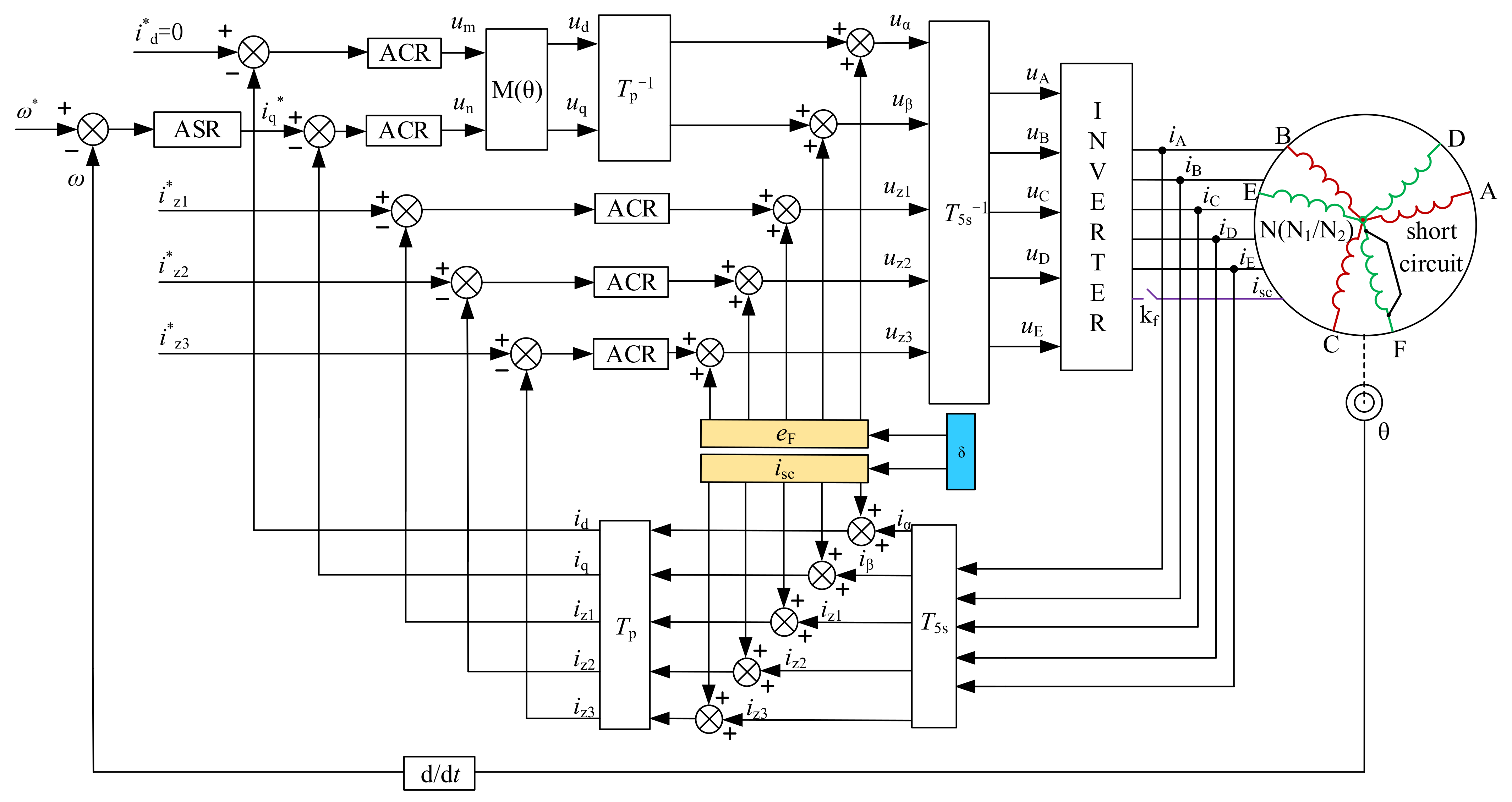
Figure 3 shows the structure of the motor system and its fault-tolerant control system under a short-circuit fault in the phase-F winding. In the figure, a short-circuit fault occurs in the phase-F winding, and corresponding reduced-order transformation matrices are shown in Equations (2) and (3), and the decoupling matrices are shown in Equations (9) and (10). In the fault case, the magnetic flux linkage generated by the permanent magnets and other phase windings generates short-circuit currents in the phase-F short-circuit winding, which is calculated as shown in Figure 4. The block diagram of the torque disturbance generated by suppressing the phase-F short-circuit current is shown in Figure 5.

4. Simulation Validation

A simulation model of the DT-PMSTM control system is constructed to verify the effectiveness of the proposed phase-F short-circuit fault-tolerant control method. The parameters of the DT-PMSTM are given in Table 1.

4.1. Short-Circuit Fault Current Analysis of the Topology with the Isolated Neutral Point

Figure 6 shows the inverter output current and the stator current when the short-circuit fault of the DT-PMSTM occurs. The motor starts with the load. The given load torque is 20 N·m and the given speed is 150 r/min during stable operation. A short-circuit fault occurs in phase-FN2 at 0.3 s. When the short-circuit fault occurs, the inverter output current increases sharply to 57 A. Even the amplitude of the output current of the remaining phase increases to different degrees, and the phase currents in winding D and winding E have a significant increase, in which the peak currents are close to 30 A, far exceeding the current of the faulted phase-FN2. Therefore, the fault-tolerant control method of the short-circuit fault is required.

4.2. Short-Circuit Fault-Tolerant Control of the System with the Isolated Neutral Point

Figure 7 shows the current, torque and speed after using the open-phase fault-tolerant control method. To keep the motor running smoothly, the magnitude and phase of the remaining phase currents are adjusted so that the synthetic MMF is the same as before the fault. Although the amplitude of each phase current is suppressed to a certain extent, the current is not sinusoidal at this time, and the speed and torque contain pulsating components.
Figure 8 shows the torque, speed and current after using the proposed short-circuit fault-tolerant control. The current waveform distortion of each phase is effectively improved. The wave shape tends to be closer to sinusoidal and the corresponding speed and torque are stable, which means that the proposed method can achieve fault-tolerant control under short-circuit fault. The fault-tolerant control strategy not only compensates for the effect of phase-FN2 short-circuit, but also suppresses the effect of the FN2 short-circuit current on healthy phases. However, the current amplitude of phase-B and phase-C does not show significant improvement compared to the phase loss situation, and the current amplitude is still high. If the motor works at high-speed and high-power conditions, the current of these two phases will greatly exceed the short-circuit current of phase-FN2, which puts forward high requirements for the inverter design. Therefore, it is considered that the neutral point mode can be connected to reduce the average value of the current amplitude of each phase and minimize the variance of the current amplitude of each phase after the fault occurs.

4.3. Short-Circuit Fault-Tolerant Control of the System with the Connected Neutral Point

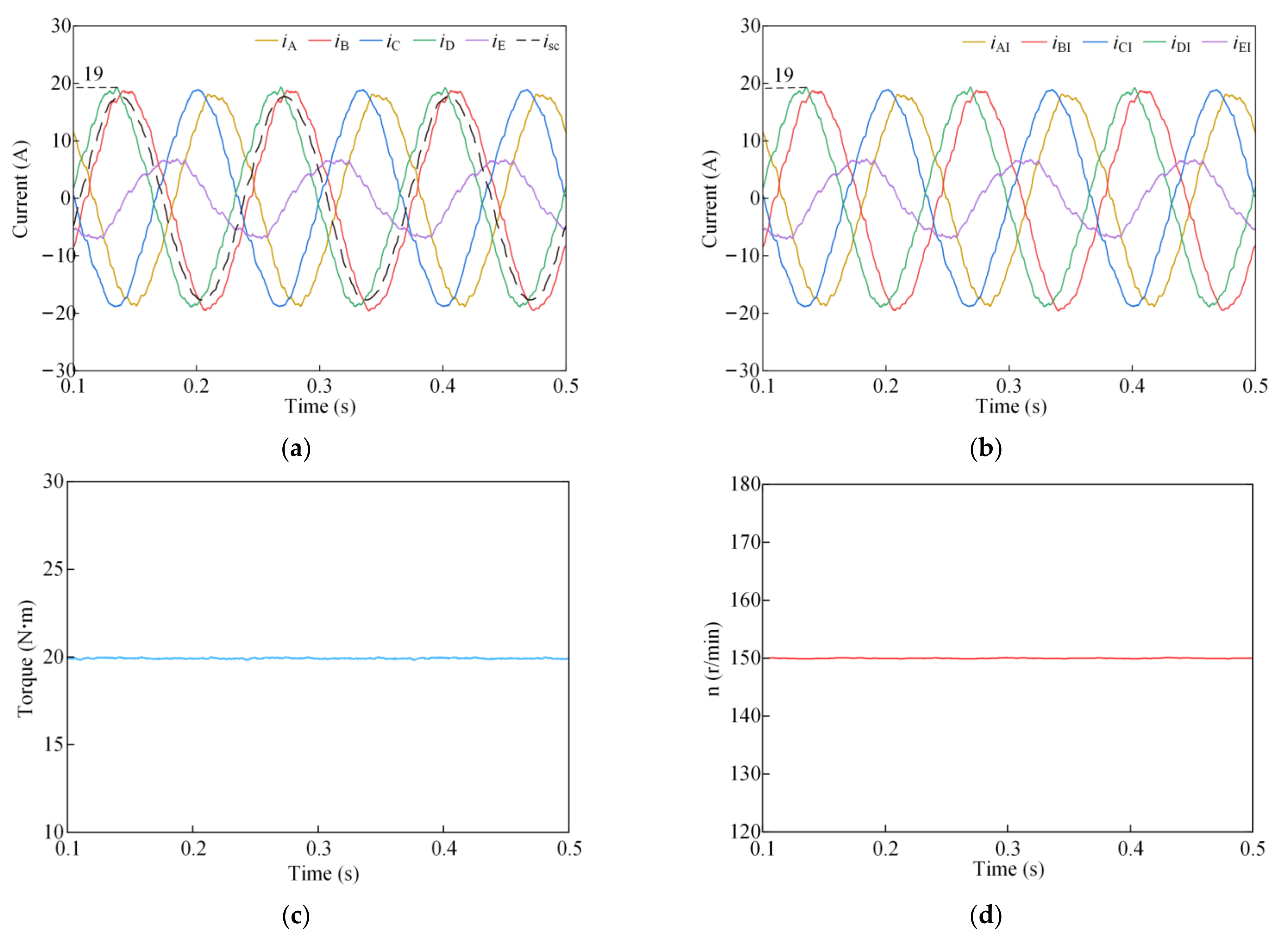
The stator current waveform in Figure 9a shows that the current amplitude of all phases tends to be the same when the neutral connection is used, except for phase E. Compared with the topology with the isolated neutral point, the phase-B current decreases from 23.5 A to 18.8 A, a decrease of 20%, and the phase-C decreases from 23.5 A to 19 A, a decrease of 19%. Figure 9b–d show that the inverter output current, speed, and torque waveforms are relatively stable, and the motor can run stably under the short-circuit fault.
Figure 10 shows the dynamic characteristics of the motor after a sudden increase and decrease in torque at 150 r/min with the short-circuit fault-tolerant control. The motor starts with a load of 20 N·m, switches to a load of 30 N·m at 0.2 s, and then to a load of 20 N·m at 0.4 s. The output torque can quickly track the sudden change of torque during the whole process, the torque pulsation is small, and the phase current sinusoidal degree is high.
Figure 11 shows the dynamic characteristics of the proposed fault-tolerant control with sudden increase and decrease of speed for a load torque of 20 N·m. The motor increases abruptly from the initial state of 150 r/min to 200 r/min in 0.15 s and decreases abruptly to 125 r/min after 0.4 s of operation. The motor current response is fast, and the average torque is almost unaffected during the speed change. Compared with the traditional method, the proposed strategy of this paper effectively reduces the computational burden of the controller, and the dynamic performance of the system after failure remains the same as that before failure. In summary, the proposed fault-tolerant control can guarantee high dynamic and static performance under short-circuit faults.
Table 2 shows the stator current amplitude, inverter output current amplitude, and total copper loss of the short-circuit fault without fault-tolerant control and with fault-tolerant control of neutral isolation and neutral connectivity. The winding current amplitude is reduced by 21.14% for the fault-tolerant control of the system with the isolated neutral point and 36.24% for the fault-tolerant control of the system with the connected neutral point compared to short-circuit fault without fault-tolerant control. For the inverter current, the fault-tolerant control method of the system with the isolated neutral point reduces the maximum magnitude by 58.84% and the fault-tolerant control method of the system with the connected neutral point reduces the maximum magnitude by 66.73% compared to the short-circuit fault non-fault-tolerant control. The fault-tolerant control method of the system with the isolated neutral point reduces the winding copper loss by 30.13% and the fault-tolerant control method of the system with the connected neutral point by 21.76% compared to the short-circuit fault non-fault-tolerant control.

5. Conclusions

In this paper, the fault-tolerant control strategy of the DT-PMSTM in the event of a short-circuit fault in the winding was studied. Based on the principle that the MMF remains unchanged before and after the fault, the dimension-reduced orthogonal transformation matrix under the open-phase fault was established. The expression of the short-circuit current was derived to eliminate the influence of the short-circuit current on the torque, and the compensation current of the remaining phases was calculated. The proposed fault-tolerant control strategy can effectively suppress the torque pulsation of the motor under the short-circuit fault and output of a stable electromagnetic torque. In contrast to the method without fault-tolerant control, the fault-tolerant control method of the system with the connected neutral point reduced the maximum winding current by 36.24% and the maximum inverter current by 66.73% while restoring the motor to output stable torque. The fault-tolerant control method of the system with the isolated neutral point reduced the winding copper loss by 30.13%. This winding short-circuit fault-tolerant control strategy has good application prospects in the field of ensuring the safe operation of electric vehicles for a long time.

Author Contributions

Conceptualization, F.H. and F.Y.; methodology, F.Y. and Z.L.; software, F.H.; validation, F.H.; formal analysis, F.H., F.Y. and Z.L.; investigation, F.H. and F.Y.; resources, F.Y. and Z.L.; data curation, F.H. and F.Y.; writing—original draft preparation, F.H.; writing—review and editing, F.H. and F.Y.; visualization, F.H.; supervision, F.Y. and Z.L.; project administration, F.Y.; funding acquisition, F.Y. All authors have read and agreed to the published version of the manuscript.

Funding

This research was funded in part by the Natural Science Foundation of Shanghai under Grant 21ZR1402300, in part by the National Nature Science Foundation of China under Grant 51837007, and in part by the Fundamental Research Funds for the Central Universities under Grant 2232019D3-53.

Conflicts of Interest

The authors declare no conflict of interest.

Nomenclature

DT-PMSTMDual three-phase permanent magnet synchronous traction motor.
T51s, 52sThe orthogonal order-reduced transformation matrixes.
TpThe park transformation matrix.
NipThe effective number of turns in each phase of the stator winding.
kwiThe stator winding factor.
iscShort-circuit current.
iA, B, C, D, E, FCompensation current for each phase.
iA,B, C, D, E, FWinding phase currents.
iAI,BI, CI, DI, EI, FIInverter output phase currents.
RStator resistance.
eA,B,C,D,E,FThe phase back electromotive forces.
Lls,msSelf-inductance and mutual inductance of the stator windings.
δ1,2Allocation coefficients of the compensation voltages in α-β coordinate.
ΨFThe magnetic flux linkage of the phase-F stator winding.
FlThe permanent magnet flux linkage.
ωThe electric angular velocity.
nRotor speed.

References

  1. Li, Z.; Khajepour, A.; Song, J. A comprehensive review of the key technologies for pure electric vehicles. Energy 2019, 182, 824–839. [Google Scholar] [CrossRef]
  2. Sun, T.; Wang, J. Extension of Virtual-Signal-Injection-Based MTPA Control for Interior Permanent-Magnet Synchronous Machine Drives Into the Field-Weakening Region. IEEE Trans. Ind. Electron. 2015, 62, 6809–6817. [Google Scholar] [CrossRef]
  3. Zhao, W.; Zheng, J.; Wang, J.; Liu, G.; Zhao, J.; Fang, Z. Design and Analysis of a Linear Permanent-Magnet Vernier Machine With Improved Force Density. IEEE Trans. Ind. Electron. 2016, 63, 2072–2082. [Google Scholar] [CrossRef]
  4. Mohammadpour, A.; Parsa, L. Global Fault-Tolerant Control Technique for Multiphase Permanent-Magnet Machines. IEEE Trans. Ind. Appl. 2015, 51, 178–186. [Google Scholar] [CrossRef]
  5. Immovilli, F.; Bianchini, C.; Lorenzani, E.; Bellini, A.; Fornasiero, E. Evaluation of Combined Reference Frame Transformation for Interturn Fault Detection in Permanent-Magnet Multiphase Machines. IEEE Trans. Ind. Electron. 2015, 62, 1912–1920. [Google Scholar] [CrossRef]
  6. Luo, Y.; Liu, C. Elimination of Harmonic Currents Using a Reference Voltage Vector Based-Model Predictive Control for a Six-Phase PMSM Motor. IEEE Trans. Power Electron. 2019, 34, 6960–6972. [Google Scholar] [CrossRef]
  7. Arafat, A.K.M.; Choi, S. Optimal Phase Advance Under Fault-Tolerant Control of a Five-Phase Permanent Magnet Assisted Synchronous Reluctance Motor. IEEE Trans. Ind. Electron. 2018, 65, 2915–2924. [Google Scholar] [CrossRef]
  8. Che, H.S.; Duran, M.J.; Levi, E.; Jones, M.; Hew, W.-P.; Rahim, N.A. Postfault Operation of an Asymmetrical Six-Phase Induction Machine With Single and Two Isolated Neutral Points. IEEE Trans. Power Electron. 2014, 29, 5406–5416. [Google Scholar] [CrossRef] [Green Version]
  9. Dwari, S.; Parsa, L. An Optimal Control Technique for Multiphase PM Machines Under Open-Circuit Faults. IEEE Trans. Ind. Electron. 2008, 55, 1988–1995. [Google Scholar] [CrossRef]
  10. Feng, G.; Lai, C.; Li, W.; Han, Y.; Kar, N.C. Computation-Efficient Solution to Open-Phase Fault Tolerant Control of Dual Three-Phase Interior PMSMs With Maximized Torque and Minimized Ripple. IEEE Trans. Power Electron. 2021, 36, 4488–4499. [Google Scholar] [CrossRef]
  11. Feng, G.; Lai, C.; Peng, W.; Kar, N.C. Decoupled Design of Fault-Tolerant Control for Dual-Three-Phase IPMSM With Improved Memory Efficiency and Reduced Current RMS. IEEE Trans. Transp. Electrif. 2022, 8, 1144–1154. [Google Scholar] [CrossRef]
  12. Xue, C.; Song, W.; Wu, X.; Feng, X. A Constant Switching Frequency Finite-Control-Set Predictive Current Control Scheme of a Five-Phase Inverter With Duty-Ratio Optimization. IEEE Trans. Power Electron. 2018, 33, 3583–3594. [Google Scholar] [CrossRef]
  13. Xiong, C.; Xu, H.; Guan, T.; Zhou, P. A Constant Switching Frequency Multiple-Vector-Based Model Predictive Current Control of Five-Phase PMSM With Nonsinusoidal Back EMF. IEEE Trans. Ind. Electron. 2020, 67, 1695–1707. [Google Scholar] [CrossRef]
  14. Gonzalez-Prieto, I.; Duran, M.J.; Aciego, J.J.; Martin, C.; Barrero, F. Model Predictive Control of Six-Phase Induction Motor Drives Using Virtual Voltage Vectors. IEEE Trans. Ind. Electron. 2018, 65, 27–37. [Google Scholar] [CrossRef]
  15. Tao, T.; Zhao, W.; Du, Y.; Cheng, Y.; Zhu, J. Simplified Fault-Tolerant Model Predictive Control for a Five-Phase Permanent-Magnet Motor With Reduced Computation Burden. IEEE Trans. Power Electron. 2020, 35, 3850–3858. [Google Scholar] [CrossRef]
  16. Luo, Y.; Liu, C. Multi-Vector-Based Model Predictive Torque Control for a Six-Phase PMSM Motor With Fixed Switching Frequency. IEEE Trans. Energy Convers. 2019, 34, 1369–1379. [Google Scholar] [CrossRef]
  17. Wang, X.; Wang, Z.; Xu, Z.; Wang, W.; Wang, B.; Zou, Z. Deadbeat Predictive Current Control-Based Fault-Tolerant Scheme for Dual Three-Phase PMSM Drives. IEEE J. Emerg. Sel. Top. Power Electron. 2021, 9, 1591–1604. [Google Scholar] [CrossRef]
  18. Sen, B.; Wang, J. Stationary Frame Fault Tolerant Current Control of Poly-phase Permanent Magnet Machines under Open-Circuit and Short-Circuit Faults. IEEE Trans. Power Electron. 2015, 31, 4684–4696. [Google Scholar] [CrossRef]
  19. AbdulRahman, A.; Galassini, A.; Degano, M.; Buticchi, G.; Cristian Pesce, G.; Gerada, C.; Bozhko, S.; Almurib, H.A.F. Open and Short Circuit Post-Fault Control Strategies for Multi-Three-Phase Interior Permanent Magnet Machines. IEEE Trans. Energy Convers. 2022, 37, 163–174. [Google Scholar] [CrossRef]
  20. Zhou, H.; Liu, G.; Zhao, W.; Yu, X.; Gao, M. Dynamic Performance Improvement of Five-Phase Permanent-Magnet Motor With Short-Circuit Fault. IEEE Trans. Ind. Electron. 2018, 65, 145–155. [Google Scholar] [CrossRef]
Figure 1. Two types of DT-PMSTM winding configurations: (a) the neutral point-isolated mode; and (b) the neutral point-connected mode.
Sustainability 14 13853 g001
Figure 2. DT-PMSTM stator winding topology.
Sustainability 14 13853 g002
Figure 3. The block diagram of torque compensation fault-tolerant control structure under phase-F short-circuit fault.
Sustainability 14 13853 g003
Figure 4. The block diagram of the short-circuit current calculation.
Sustainability 14 13853 g004
Figure 5. The block diagram of torque disturbance suppression under phase-F short-circuit fault.
Sustainability 14 13853 g005
Figure 6. Inverter output currents and stator currents before and after the fault occurs: (a) inverter output currents; and (b) stator currents.
Sustainability 14 13853 g006
Figure 7. Open-phase fault-tolerant control under short-circuit fault of the system with the isolated neutral point: (a) stator current; (b) inverter output current; (c) torque; and (d) speed.
Sustainability 14 13853 g007
Figure 8. Fault-tolerant control under short-circuit fault of the system with the isolated neutral point: (a) stator current; (b) inverter output current; (c) torque; and (d) speed.
Sustainability 14 13853 g008
Figure 9. Fault-tolerant control under short-circuit fault of the system with the connected neutral point: (a) stator current; (b) inverter output current; (c) torque; and (d) speed.
Sustainability 14 13853 g009
Figure 10. Dynamic characteristics under sudden increase and decrease of torque: (a) stator current; and (b) torque.
Sustainability 14 13853 g010
Figure 11. Dynamic characteristics under sudden increases and decreases in speed: (a) stator current; and (b) speed.
Sustainability 14 13853 g011
Table 1. Parameters of the DT-PMSTM.
ParameterValue
Number of pole pairs3
Stator resistance (R, Ω)0.8
Stator winding self-inductance (Lls, mH)1.46
Stator winding mutual inductance (Lms, mH)1.06
Fundamental flux linkage of the rotor permanent magnet pole (Fl, Wb)0.30
Rotational inertia (kg·m2)0.015
Rated torque (N·m)30
Table 2. Simulation results of three control methods under different winding connection modes.
ParameterShort-Circuit Fault without Fault-Tolerant ControlFault-Tolerant Control of the System with the Isolated Neutral PointFault-Tolerant Control of the System with the Connected Neutral Point
The amplitude of phase-A current (IA, A)7.57.818.0
The amplitude of phase-B current (IB, A)7.523.519.0
The amplitude of phase-C current (IC, A)7.523.519.0
The amplitude of phase-D current (ID, A)29.56.518.7
The amplitude of phase-E current (IE, A)29.86.56.5
The amplitude of short-circuit phase current
(ISC, A)
17.917.917.9
The amplitude of inverter phase-A output
current (IAI, A)
7.57.818.0
The amplitude of inverter phase-B output
current (IBI, A)
7.523.519.0
The amplitude of inverter phase-C output
current (ICI, A)
7.523.519.0
The amplitude of inverter phase-D output
current (IDI, A)
29.56.518.7
The amplitude of inverter phase-E output
current (IEI, A)
29.86.56.5
The amplitude of inverter phase-F output
current (IFI, A)
57.100
Total copper loss (W)898.9628.1703.3
Winding current maximum reduction
percentage (%)
/21.1436.24
Inverter current maximum reduction
percentage (%)
/58.8466.73
Winding copper loss maximum reduction
percentage (%)
/30.1321.76
Publisher’s Note: MDPI stays neutral with regard to jurisdictional claims in published maps and institutional affiliations.