Article

An Optimal Layout Model of Curved Panels for Using 3D Printing

1
School of Civil, Environmental and Architectural Engineering, Korea University, Seoul 02841, Korea
2
Korea Institute of Procurement, Seoul 06226, Korea
3
Department of Architecture, Soonchunhyang University, Asan 25601, Korea
4
Department of Fire Safety Management, Seojeong University, Yangju 11429, Korea
5
Architectural Engineering Program, School of Architecture, Seoul National University of Science and Technology, Seoul 01811, Korea
*
Authors to whom correspondence should be addressed.
Sustainability 2022, 14(21), 13896; https://doi.org/10.3390/su142113896
Submission received: 5 October 2022 / Revised: 18 October 2022 / Accepted: 23 October 2022 / Published: 26 October 2022

Abstract

:
Recently, the application of 3D printing in the production of curved panels has increased due to the irregular shape of free-form buildings. In general, 3D printing based on additive manufacturing (AM) methods requires various supports that cause a waste of printing materials and an increase in production time. In this study, we proposed a method for printing a pair of panels that can hold each other through the minimal support connected between each panel. However, this printing method causes an additional non-productivity factor called the non-printing path for the nozzle to move between the pair of panels. Therefore, we also developed an optimal layout model that can minimize non-printing paths and used the genetic algorithm (GA) for its calculation. As a result of applying the optimization model proposed in this study through the case study, the non-printing path was reduced by 18.54% compared with that from the existing method, and the non-printing time was reduced by 34.41 h. The total production time, including non-printing time and printing time, was reduced by 3.89%, and the productivity was improved by 4.04%. The model proposed in this study is expected to minimize unproductive factors that occur in the process of manufacturing curved panels and reduce the energy consumption.

1. Introduction

Recently, architects have taken approaches to reflect various concepts in their works, leading to a rise in the number of free-form buildings [1,2]. Since a free-form structure has a facade with a geometric frame, the surface also has doubly-curved cladding panels [3]. These panels are shaped and processed via rolled molding. However, manufacturing method characteristics, such as casting angle and non-re-entrant shape [4], cause deterioration in the curvature quality of the curved panels, resulting in increased costs when making complex shapes [5].
Three-dimensional (3D) printing is a suitable alternative for resolving these problems, and its application in irregular-shaped buildings is increasing [6]. The method of 3D printing constructs a shape by stacking layers on top of each other in an additive manufacturing (AM) process [7,8,9], which has become one of the most revolutionary technological applications in manufacturing [10]. The AM process does not require a form and is highly cost-effective, as it significantly reduces material waste [11]. Moreover, the process is suitable for curved panels because there are no limits to the expression of the curvature, and it is possible to express the required shape and improve the quality [12,13].
The printing method of curved panels with a 3D printer is crucial for determining the panel quality and production time [14]. Due to the characteristic of the AM method, printing the panels in the longitudinal direction is advantageous in terms of quality and production time. However, additional support is required in the overhang section if the curvature radius of the curved panels is considerably large, as the panel might bend or collapse during production [15,16]. As the number of supports increases, problems such as printing material waste and longer printing times occur [17,18].
Accordingly, in order to remove these unproductive factors caused by additional supports, a method for minimizing support by removing the overhang features [16,19] and changing the shape [15] or angle [17,18,20,21] of the overhang has been discussed. However, such methods are not suitable for printing curved panels based on a design document that must be produced with minimal manufacturing errors. In addition, the slicing programs and printing software of existing 3D printers are aimed at optimizing the printing of a single target. These are types of software that determine the direction or support installation according to the printing shape, and there is no function to print multiple objects in a bundle or to divide objects [16,20]. For these reasons, a method of printing a pair of panels supporting each other with minimal support has emerged, which has proven to be highly efficient for manufacturing curved panels [22].
This manufacturing method has the advantage of minimizing the support structure; however, when printing a pair of panels, the pair must be printed while moving between the two panels. The moving distance generated during the production is a non-productive moving distance that unnecessarily increases the printing time. This has an enormous effect on the overall production time, especially if the number of panels is great, and affects the durability of the printer. Additionally, there is a limit to intuitively searching for alternatives, as there are countless alternatives depending on the panel combination and arrangement method. In order to increase the productivity of the curved panels of the free-form facade, an alternative search method is required that can minimize the non-printing distance between panels.
Therefore, this study proposes a model that minimizes the non-productive movement and improves productivity when printing curved panels using a 3D printer. This study focuses on the print preparation stage of the panel, and the scope of the study is to propose a method for the layout and combination of a pair of panels before printing. For this purpose, this study constructs an algorithm considering the number of printing cases, and conducts research by generating alternatives through an optimization method. In order to achieve this aim, this paper first examines the existing research on the 3D printing technology utilized in architecture. Next, this study proposes an optimal layout model that can minimize the distance of the non-printing path and explain the main algorithms and processes. Finally, the proposed model is applied to an experimental case for assessing the improvement in productivity. The findings of this study are expected to minimize the non-productive factors and reduce energy consumption in the manufacturing process of curved panels.

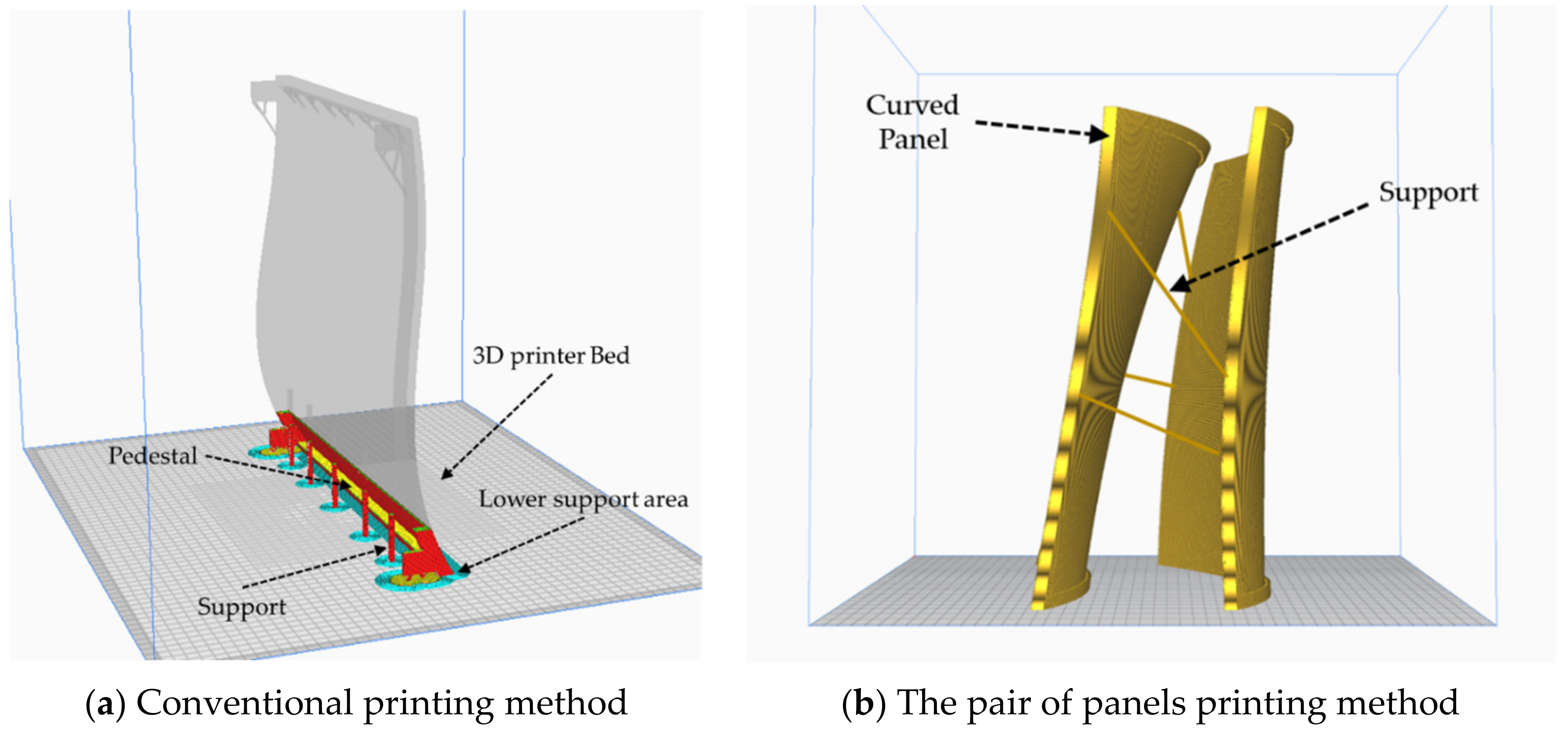
2. 3D Printing Method for Curved Panel

Theoretically, there are no form limitations for 3D printing. However, there are some restrictions due to the characteristics of the AM method. Among such restrictions, overhang and balancing are considered as critical issues pertaining to the printing [15]. In the AM method, the next layer must be partially overlapped with the previous layer so that it can be supported. Depending on the degree of such overhang, the printing may be limited, and a design that minimizes hanging parts is required [17,23]. To overcome the physical limitations of overhang, additional support is necessary. These supports can be removed after the printing is complete, but this causes waste materials and increases the printing time [24]. It is also important to maintain equilibrium without the object falling over during the printing process. This problem can be solved by balancing or properly filling the internal structure of the mass of the object, or by using a pedestal [25]. However, depending on the shape, the internal filling may be difficult, and the pedestal increases the material and printing time as support.
Due to the characteristics of the curved panel, the limitation of the AM printing method should be considered. The panel plate shaped with a curve, has a longitudinal direction and a thin width. Also, multiple panels of the same module size should be printed. To minimize the use of hanging parts, it is advantageous to print a long panel in the longitudinal direction. By printing in the longitudinal direction, a support should be formed in the section that exceeds the overhang limit depending on the degree of curvature of the panel. However, even if propped up by a support, it is still easy for the panel to fall over while the support is being constructed due to the panel characteristic of a small lower support area. Therefore, an additional pedestal or support is required for the curved panel output, causing a further waste of material and printing time (Figure 1a).
Using the feature of printing multiple curved panels, the problem can be solved if two sheets are supported together. By connecting and printing supports that can support both curved surfaces, the number and length of the supports will be reduced, thus preventing material waste and an increase in printing time. Moreover, since the support is connected in the middle and the contact area with the bed is enlarged, it is possible to prevent falling during printing. Therefore, the method of printing curved panels against each other was set as the scope of this study (Figure 1b).
However, in the case of printing two sheets simultaneously, additional time is required. Each layer takes time to move between the two panels. The movement time between panels is repeated for every layer and becomes a non-productive factor. For a curved panel, the curvature of each layer is different; therefore, the distance varies according to the type and arrangement method of the panel. Additionally, since the number of panels is great, countless alternatives are created depending on the method of joining the two sheets, making it difficult to calculate all instances of these non-productive movement paths. Accordingly, at present, arbitrary numbers are assigned to the panels, and the panels are printed sequentially in pairs, and the process of the movement path between each panel is not considered. However, since this path occupies a large proportion of the production time, a mathematical optimization method is required to minimize the non-productive movement path in order to increase the productivity of the curved panel.

3. Previous Research on 3D Print Planning

3.1. Overhang

As mentioned previously, when producing curved panels, overhangs are accompanied by supports to prop them up, which leads to productivity problems such as material wastage, an increase in printing time, and post-fabrication treatments to remove the supports. Accordingly, Mumtaz et al. [16] and Cloots et al. [19] tried to remove the overhang features that cause decreased productivity in advance. Cacace et al. [15] proposed a method of fixing the overhang without using a support through shape optimization based on the level set method, which has the advantage of avoiding additional material for the support, excess printing time, and the final detaching operation of having to remove the vertical support structures—a process that causes unproductive factors. However, shape optimization requires a very precise computational grid to hold up the overhangs without supports, which is a limitation of the study as there are many cases in which it is difficult to discard the support completely.
Moreover, Van de ven et al. [17] used a front propagation-based overhang filter to detect overhang in advance and derived a minimum overhang angle that does not require a support structure. Through this, they attempted to present an optimal 3D design that could reduce the amount of material required for support in printing. Gaynor and Guest [18], Leary et al. [20], and Hu et al. [21] also paid attention to deriving the minimum allowable self-supporting angle so that the designed components and structures could be printed without the use of support material.
Previous studies on overhangs mainly tried to block the use of supporters that cause unproductive waste by removing the overhang features themselves or changing the shape or angle of the overhang in advance. However, the method of removing or deforming overhangs to minimize the use of supports is not desirable from the viewpoint of producing a curved panel based on the design document with minimum manufacturing error.
Furthermore, the two panels related to the printing method of this study, prop each other up through the support connected between them and have a morphological stability that can help them stand on their own (refer to Figure 1b). Therefore, even if the support structure is not completely excluded, the pair of panels printing method can support the overhang and secure the quality of the produced panels with minimal support.

3.2. Optimal Path Plan of 3D Printing

The pair of panels printing method proposed in this study enables minimal installation of supports due to the morphological and structural stability of the printed product. However, since this method produces two panels with one output as the basic unit, a non-production time is generated in addition to the panel production time, due to the time required for the nozzle to move the distance between the two panels to the non-printing state. Therefore, minimizing the non-production time is key to improving the productivity of the pair of panels printing method, which can be solved by optimizing the movement path of the 3D print nozzle.
Additionally, it is advantageous to output a long curved panel in the longitudinal direction to minimize the hanging parts, wherein thousands of thin layers are stacked to form a panel object. The layer of each layer can be described as a 2D horizontal cross section with x and y directions where the 3D print nozzle moves along the selected path within the cross section, and the printing proceeds. In other words, finding the best path for 3D printing is related to the problem of finding the best path for a layer.
In layered manufacturing (LM) such as curved panel production, the path optimization problem can typically be solved by using the following two methods [26]. One approach is by using the Asymmetric Traveling Salesman Problem and the Assign Problem, and the other is based on the genetic algorithm (GA) approach.
First, Lechowicz et al. [27] and Yin et al. [28] tried to solve the 3D print route optimization problem by recognizing it as a traveling salesman problem (TSP). Lechowicz et al. [27] derived the shortest time to complete the entire path by implementing hybrid algorithms such as the Greedy 2-opt and Greedy annealing, and then comparing and reviewing the respective results. Yin et al. [28] reduced the number of paths, non-productive travel distance, and number of nozzles compared with those from the existing path plan by proposing an ant colony algorithm-based path plan. The above studies were conducted for single-layered structures, and path optimization was made possible by using the traditional TSP. However, for resolving problems involving multiple layers, as in this study, additional research is needed to solve the increased number of variables.
Contrastingly, Wojcik et al. [29] tried to solve the path optimization problem based on a genetic approach. In this study, after generating the path of the 3D printing nozzle with the modified zig-zag algorithm, the optimal path was derived through the GA. The application of the GA made it possible to optimize the path of multiple layers, which is relatively complicated compared with a single layer.
In the case of irregular-shaped building finishing materials, the subject of this study, the types of panels to be produced are diverse and there are countless combinations and arrangement methods of panels due to the pair of panel printing method. In other words, it is difficult to approach and solve the traditional TSP problem as the variables to be considered for path optimization are diversified and the number of calculations for the moving distance increases exponentially. Therefore, this study intends to implement an algorithm that can minimize the non-productive travel distance through a genetic approach and present a model.

4. Optimizing Curved Panel Printing Layout

4.1. Panel Printing Method in Pairs

The method of simultaneously printing a pair of panels was to select two panels, lay them out so that they did not overlap, and then print them. As each panel was printed, the parts that could be crossed by overhangs were connected to each other with supports to be propped up (refer to Figure 1b). The printing of the panel caused the two panels to be printed as the same layer. This was because by making the two printing layers the same, the vertical movement of the nozzle could be eliminated, and the layers of the two panels could be held up by the supports during printing. This method minimized the amount of support needed and enabled printing, whereby an improvement in quality and speed could be expected.
In order to further improve the printing productivity of the method, it was necessary to minimize unnecessary movement. This method inevitably required movement between the two panels at least once per layer. This movement was unproductive, and thus needed to be minimized to shorten the overall printing time. The moving length varied depending on the panel layout, and the number of panel combinations rose rapidly as the number of panels increased.

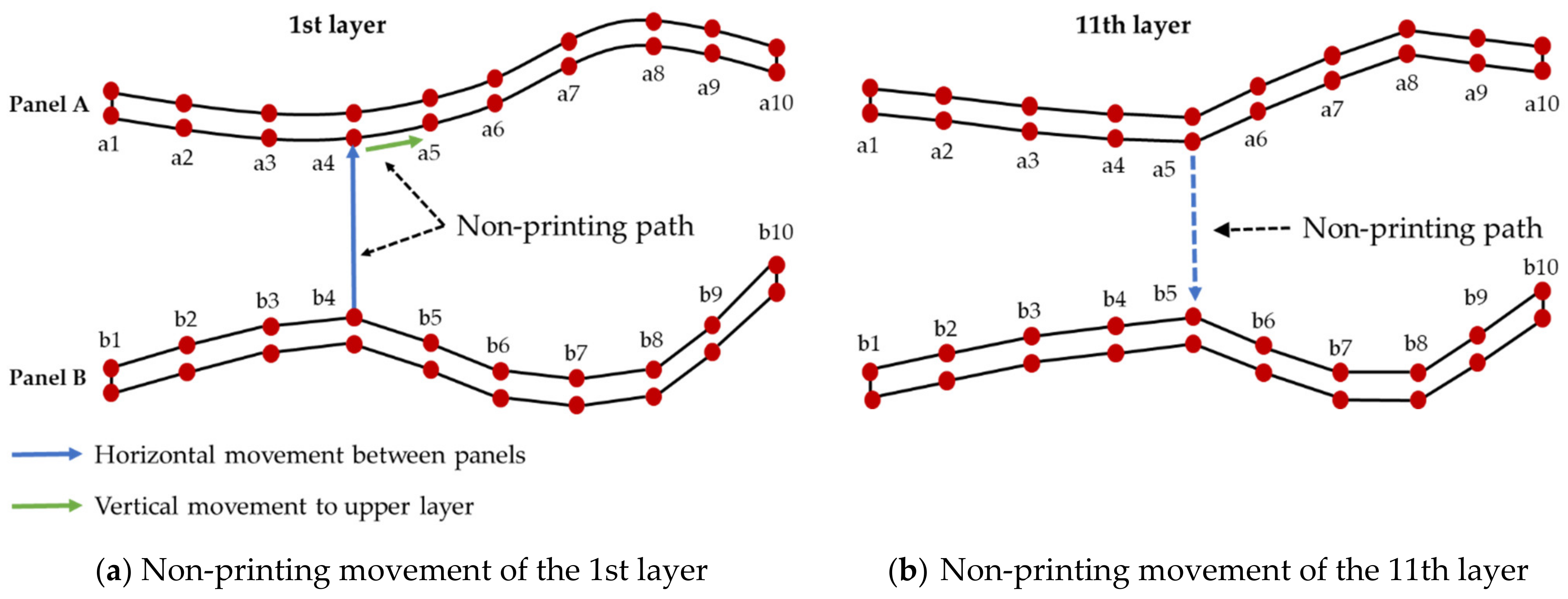
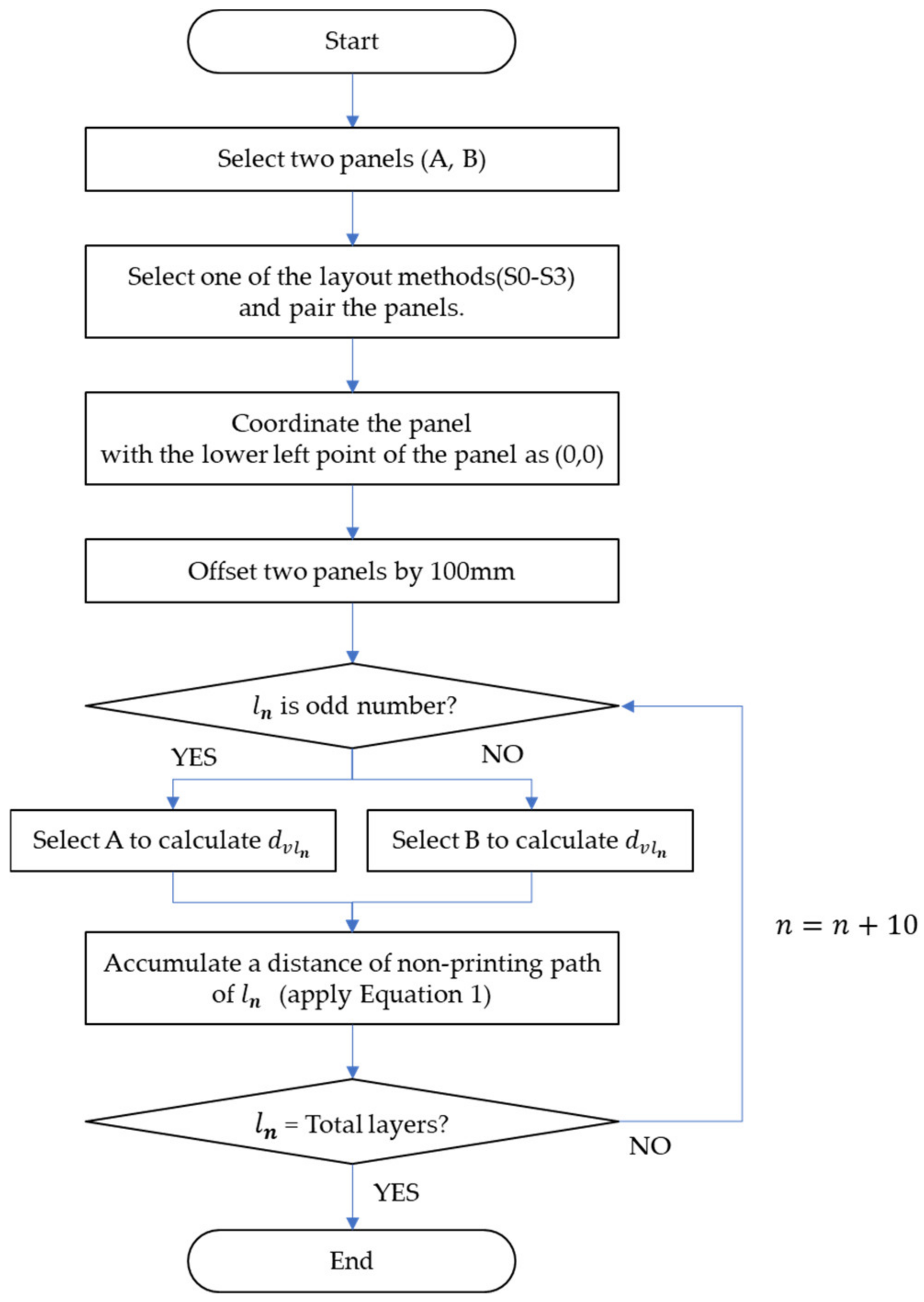
4.2. Calculation of Non-Printing Paths

In this study, the movement length for the corresponding route was first calculated to minimize the non-productive movement path. The movement of the nozzle was made by the coordinates’ input according to the nozzle size and the layer height, but the calculation became complicated with the coordinates. Since the curve did not change abruptly even in the curved panel, this study derived the coordinates by dividing the panel into a certain number of units to simplify the calculation. A plane divided the inner line of the panel into 10 coordinates, and the vertical layer was divided into 10 units; this unit was derived as a value at which the model operation was performed smoothly through several tests.
To minimize the movement path, the movement method between panels was set by drawing all the layers of one panel and then drawing the layers of the next panel. When drawing with two moving panels, the movement between panels increased; therefore, after completing the layer of the first panel, it moved to the shortest path from the end point to the layer of the next panel. In general, the shortest distance at this time means a straight-line motion. Then, after printing the second panel, the output of one layer was completed. In the next layer, two points were found with the minimum distance again, and they were moved horizontally to the corresponding points; the printing process continued from the second panel (Figure 2).
To calculate the movement distance, the movement distance that was not output was calculated for every 10 layers and the non-printing movement distance of each layer was summed. First, the movement distance between the two panels in the same layer was calculated by connecting 10 points on the same axis on the plane to each other. Among these, the two points with the smallest movement distance were calculated, and then calculated again as the movement distance between the panels of the corresponding layer. In addition, in the next layer, the point with the minimum movement distance was calculated and the movement distance to the corresponding point was added.
For example, in the case of Figure 2, if the minimum distance points of the first layer are a4 and b4 (Figure 2a), and the minimum points of the 11th layer are a5 and b5 (Figure 2b), the sum of the non-printing path distances of the first layer becomes dhl₁ + dhl₁₁. Where dhl₁ is a horizontal distance of the non-printing path of the 1st layer, dhl₁₁ is a horizontal distance of the non-printing path of the 11th layer. Since the layer is calculated in units of 10, it is assumed that the actual movement between panels is performed 10 times, and the movement between points is calculated by setting it as one operation. Finally, if all layers derived in units of 10 are added together, this becomes the non-productive movement distance when producing two panels.
The formula for calculating the distance of the non-printing path based on this is the same as Equation (1).
Distance of non-printing path = ∑ (dhlₙ × 10 + dvlₙ)
where ln is the nth layer, dhlₙ is the horizontal distance of the non-printing path in the nth layer, and dvlₙ is the vertical distance of the non-printing path in the nth layer.

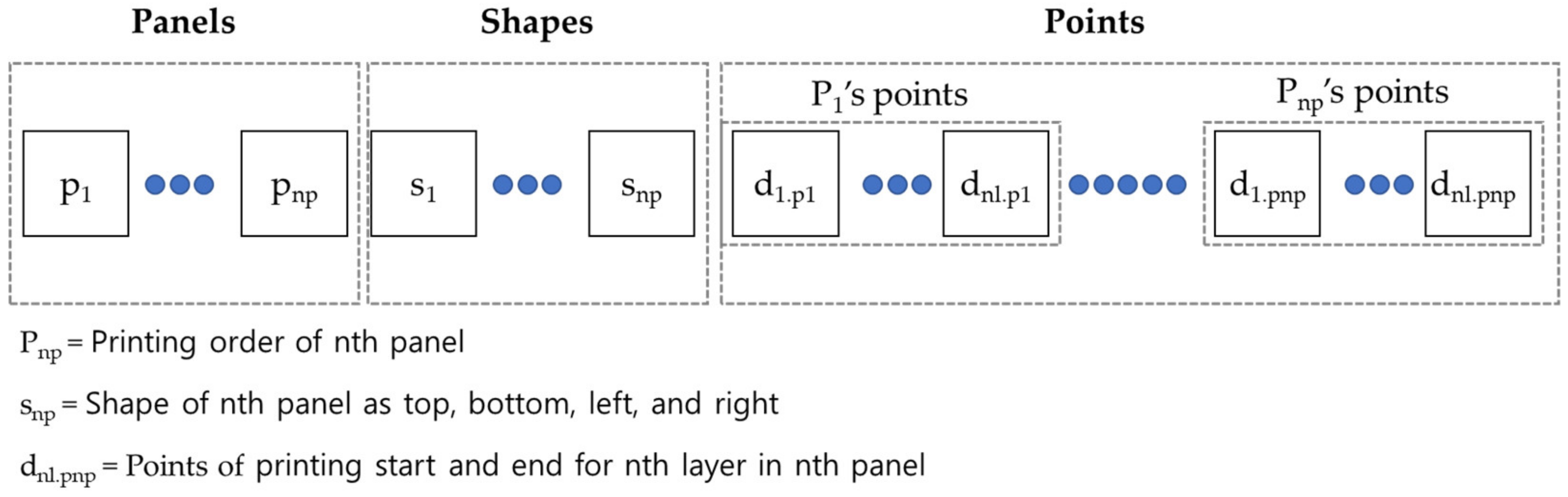
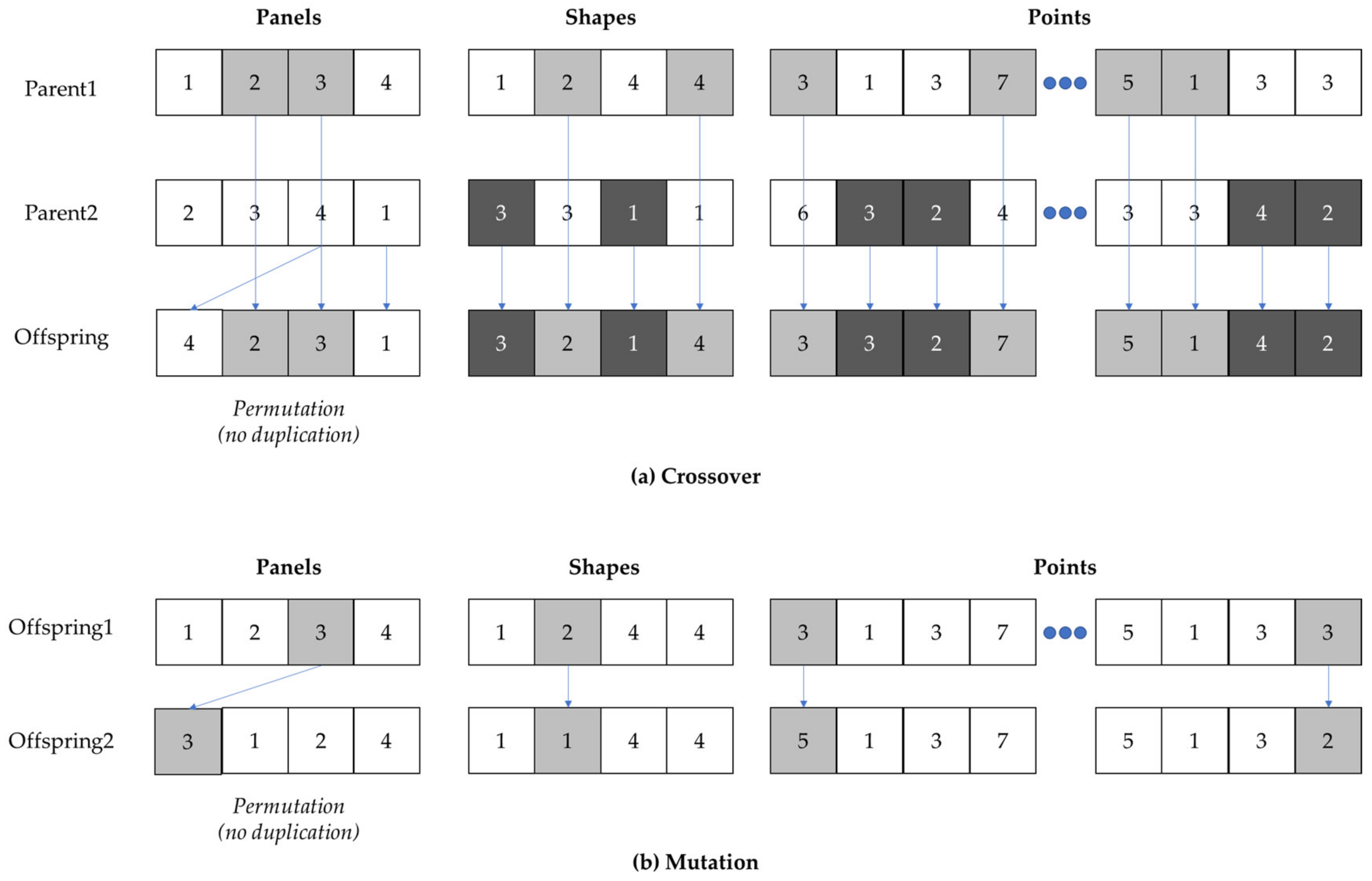
4.3. Printing Layout Optimization Model

The non-printing movement path of the two panels differed depending on the panel type and layout method. The shape of the panel differed depending on the type of panel, and it was determined by how the two panels were selected. There were a total of four ways to layout the panel: a basic panel, a panel rotated left and right by 180°, a panel rotated up and down by 180°, and a panel rotated both up and down and left and right (Figure 3). As a result, the non-printing movement path was determined by how the two panels were selected and laid out using one of the four methods. Because the number of cases of panel selection and the number of printing layers were great, an optimization model was required for the calculation.
Figure 4 shows a model for optimizing panel layout. First, two panels were randomly selected among all the panels. Next, one of the panel layout methods (S0–S3) was selected to set the panel type and arrangement.
Next, the coordinates for the calculation of the two panels were set. After placing one panel, the coordinates of the lower left corner of one panel was noted as a reference point. The second panel was also placed horizontally on top of the corner of the first panel. While the panels were printed, the two panels were placed 100 mm apart based on the closest layer, as they should not overlap. Then, the coordinates of the second panel were set. Afterwards, the layer was checked to see whether it was an odd or even layer; if the layer was odd, the dvlₙ of panel A was calculated; if the layer was even, the dvlₙ of panel B was calculated.
Next, the distance of the non-printing path between the two panels was accumulated. The previously derived Equation (1) was used to calculate the distance. Based on the coordinates of the two panels, the distance was calculated by summing up the moving distance, and the summation was terminated as the total layers were completed.
Finally, we proceeded with the optimization of the calculation. The algorithm used was a GA, and the optimization was performed by composing the type and shape of the panel with genes. The chromosome for the optimal path problem consisted of panels, shapes, and points parts. Panels indicates the printing order of each panel, shapes indicate the layout of each panel as top, bottom, left, and right, and points indicate the printing start and end points for each layer in every panel (Figure 5).
For crossover, permutation was applied because there should be no order overlap in the case of panels, while the overlapping of shapes and points was possible. In the event of a mutation, the method applied in the case of the panels consisted of inserting a gene from a selected to a random position so that it would not overlap (Figure 6).

5. Case Study

5.1. Case Overview

A case study was performed to verify this model. The object to be printed was an irregular-shaped wall. The wall was composed of 100 double-curved panels of 400 mm × 400 mm size, and all panels had different shapes. As for the 3D printer, a large-format printer was used; the nozzle speed was 35 mm/min; and approximately 1300 layers were stacked to print a panel of the corresponding size, which took 7 h. The printing method was to print two panels at once from the bed (Figure 7).

5.2. Result and Discussion

The existing layout method and the layout method proposed in this study were compared. In the existing method, each pair was configured from the left and printed without any change in direction. The model proposed in this study produced the outputs through a GA. The GA requires several empirical tests to set parameters, such as the number of generations, population size, crossover rate, and mutation rate, that affect the performance of the proposed model. The population size for tests was set in a range between a lower bound of 100 and an upper bound of 300 with a test interval of 100, while the crossover rate had a lower bound of 0.5 and an upper bound of 0.9 with a test interval of 0.1. The mutation rate had a lower bound of 0.05 and an upper bound of 0.15 with a test interval of 0.05. The maximum generation number was set as 5000. After a series of trial-and-error adjustments, the number of generations equal to 3000, a population size equal to 100 individuals, a crossover rate equal to 0.7, and a mutation rate equal to 0.1 were found to converge towards the minimal distance quickly. Table 1 shows the results of the printing path and layout shape through the panel layout optimization model.
Table 2 shows the results of calculating the distance of the non-printing path, non-printing time, printing time, and total printing time based on the above results. In the existing method, a non-printing movement path length of 23,380,538 mm was derived. In terms of production time, 888.56 h was required to print 100 sheets, of which 185.56 h was due to non-printing movement and accounted for 26.51% of the total production time. For the proposed model, 19,044,898 mm of non-printing movement path length was derived; of the total production time of 851.15 h, 151.15 h was due to non-printing movement, which accounted for 21.59% of the total production time.
When the proposed model was used for output, the distance of the non-printing path was reduced by 18.54%. This means that the efficiency of non-printing movement increased by approximately 22.77% compared with the conventional model by reducing only the non-production factors while maintaining the production time as it is. The production time could be shortened by reducing the time due to non-printing by 34.41 h.
The printing time of the entire panel using this model was reduced by 31.41 h compared with the previous method, whereby reducing the total production time by 3.89%. This means that the panel output productivity increased by 4.04% by changing only the layout without changing the equipment specifications or the panel. This was the result of applying the model to the case study wall composed of 100 panels. When it is assumed that this result is applied to the wall of an actual building finished with irregular-shaped panels, the time reduction effect is greatly increased. For example, in the case of the Dongdaemun Design Plaza (DDP), which is a representative building in Korea constructed using curved panels with the finished area of irregular-shaped panels calculated as 33,228 m2, the total printing time could have theoretically been reduced by 71,640 h when the model of this study is applied to the calculations. Although there are differences in the number of 3D prints and printing methods, our proposed method could mean very great savings in terms of production time.
A reduction of production time can be expected to reduce power consumption and improve durability. It is possible to reduce the amount of electricity used by reducing the travel length for overall production, which can result in a reduction in carbon emission due to a reduction in energy use. Additionally, the lifetime of the nozzle can be extended by reducing the moving distance of the nozzle, and the durability of the printer can be improved by shortening the overall printer-usage time. In addition, by using this printing method, it is possible to reduce the overall support-removal time, which is considered to be a post-processing activity, by minimizing the number of support structures needed. Furthermore, the quality of the panel can be improved by reducing the occurrence of defects that are concerned when the support is removed.
Through the results of this study, some panels of the case study were printed as a test (Figure 8a). Figure 8b is a photo of two panels printed as a pair. As a result, in the process of printing these panels, there was no collapse of panels since the two panels were supporting each other through minimal supports. In addition, it was possible to secure the quality of printing panels without manufacturing errors.
Since the support was attached between the two printed panels, post-processing activity to remove the support after printing was required. When the gap between the two panels was narrow, the support could not be removed from the panel smoothly, so an additional surface treatment was performed after the support was removed. Further studies are needed to determine the location and number of supports in order to simplify post-treatment processes that occur after printing.
This model has a limitation in that it can only be used when two panels are attached and printed. There is also a disadvantage in that it can only be applied when the sizes of the panels are similar. In addition, further research is needed to minimize the calculation time required for a great number of panels. Moreover, the results of this study do not affect the printing path of the panel, but they do affect the printing direction of the panel, so additional tests are required for the effect.

6. Conclusions

This study proposed a curved panel layout optimization model that can minimize the non-printing path. As a result of applying the proposed model through the case study, the distance of the non-printing path was reduced by 18.54% compared with that from the existing method, and the non-printing time was reduced by 34.41 h. The total production time, including non-printing time and printing time, was reduced by 3.89%, and a productivity improvement of 4.04% was possible through the optimization of the panel layout without changing the specifications of the 3D printing equipment or correcting the overhangs.
A reduction in 3D printing production time means a reduction in power consumption, which leads to a reduction in energy use and a reduction in carbon emissions in the production process. In addition, the reduction in the travel distance of the 3D printing equipment through this model extends the life expectancy of the related parts such as nozzles and enables a reduction of maintenance costs. Furthermore, we believe that the results of this study can greatly contribute to the application of 3D printing in construction. One important characteristic of construction materials is that they are large in size and consist of several components. Considering that the production speed of printing these materials using 3D printers based on conventional printing methods increases significantly, the relevant time can be reduced significantly through the proposed method in this study. Furthermore, the proposed method can be applied not only to panels but also to materials in various fields, such as blocks, finishing materials, and public facilities.
In this study, the use of the model is limited to a pair of panels, and there is another limitation wherein a lot of time would be required to calculate if the number of panels increases to that of an actual building level. Therefore, further research will be conducted on the extension of the optimization model considering other production methods and the application of a hybrid technique that can supplement the GA calculation time.

Author Contributions

Conceptualization, H.C. and H.L.; methodology, M.C. and T.K.; writing—original draft preparation, M.C. and H.L.; writing—review and editing, C.-W.K., T.L., and B.-J.K.; supervision, T.K. and H.L.; funding acquisition, H.C. and H.L. All authors have read and agreed to the published version of the manuscript.

Funding

This work was supported by the Korea Agency for Infrastructure Technology Advancement (KAIA) grant funded by the Ministry of Land, Infrastructure and Transport (Grant 22ORPS-B158109-03), and by the Soonchunhyang University Research Fund and the Korea Agency for Infrastructure Technology Advancement (KAIA) grant funded by the Ministry of Land, Infrastructure and Transport (Grant 22CTAP-C163802-02).

Institutional Review Board Statement

Not applicable.

Informed Consent Statement

Not applicable.

Data Availability Statement

Not applicable.

Conflicts of Interest

The authors declare no conflict of interest.

References

  1. Kavuma, A.; Ock, J.; Jang, H. Factors influencing time and cost overruns on freeform construction projects. KSCE J. Civ. Eng. 2019, 23, 1442–1450. [Google Scholar] [CrossRef]
  2. Mosoarca, M.; Anastasiadis, A.; Apostolos, K. Are freeform architectures ecological buildings? J. Environ. Prot. Ecol. 2014, 15, 366–373. [Google Scholar]
  3. Lim, S.; Buswell, R.A.; Valentine, P.J.; Piker, D.; Austin, S.A.; De Kestelier, X. Modeling curved-layered printing paths for fabricating large-scale construction components. Addit. Manuf. 2016, 12, 216–230. [Google Scholar] [CrossRef] [Green Version]
  4. Hague, R.J.M.; Campbell, I.; Dickens, P. Implications on design of rapid manufacturing. Proc. Inst. Mech. Eng. Part C J. Mech. Eng. Sci. 2003, 217, 25–30. [Google Scholar] [CrossRef] [Green Version]
  5. Jovanović, M.; Raković, M.; Tepavčević, B.; Borovac, B.; Nikolić, M. Robotic fabrication of freeform foam structures with quadrilateral and puzzle shaped panels. Autom. Constr. 2017, 74, 28–38. [Google Scholar] [CrossRef]
  6. Kim, S.; Park, Y.; Park, J. Review of Freeform Buildings using CNC T-BAR System. In Proceedings of the Korean Society of Architecture and Construction Engineering Conference, Gyeongju, Korea, 17–19 May 2017. [Google Scholar]
  7. Khoshnevis, B.; Hwang, D.; Yao, K.T.; Yeh, Z. Mega-scale fabrication by contour crafting. Int. J. Ind. Syst. Eng. 2006, 1, 301–320. [Google Scholar] [CrossRef] [Green Version]
  8. Lim, S.; Buswell, R.A.; Le, T.T.; Austin, S.A.; Gibb, A.G.F.; Thorpe, A. Developments in construction-scale additive manufacturing processes. Autom. Constr. 2012, 21, 262–268. [Google Scholar] [CrossRef] [Green Version]
  9. Muflikhun, M.A.; Sentanu, D.A. Characteristics and performance of carabiner remodeling using 3D printing with graded filler and different orientation methods. Eng. Fail. Anal. 2021, 130, 105795. [Google Scholar] [CrossRef]
  10. Nugraha, A.D.; Ruli; Supriyanto, E.; Rasgianti; Prawara, B.; Martides, E.; Junianto, E.; Wibowo, A.; Sentanuhady, J.; Muflikhun, M.A. First-rate manufacturing process of primary air fan (PAF) coal power plant in Indonesia using laser powder bed fusion (LPBF) technology. J. Mater. Res. Technol. 2022, 18, 4075–4088. [Google Scholar] [CrossRef]
  11. Papacharalampopoulos, A.; Bikas, H.; Stavropoulos, P. Path planning for the infill of 3D printed parts utilizing Hilbert curves. Procedia Manuf. 2018, 21, 757–764. [Google Scholar] [CrossRef]
  12. Hopkinson, N.; Gao, Y.; McAfee, D.J. Design for environment analysis applied to rapid manufacturing. Proc. IMechE Part D J. Automob. Eng. 2006, 10, 1363–1372. [Google Scholar] [CrossRef]
  13. Buswell, R.A.; Soar, R.C.; Gibb, A.G.F.; Thorpe, A. Freeform Construction: Mega-scale rapid manufacturing for construction. Autom. Constr. 2007, 16, 224–231. [Google Scholar] [CrossRef] [Green Version]
  14. Ezair, B.; Fuhrmann, S.; Elber, G. Volumetric covering print-paths for additive manufacturing of 3D models. Comput. Aided Des. 2018, 100, 1–13. [Google Scholar] [CrossRef]
  15. Cacace, S.; Cristiani, E.; Rocchi, L. A level set based method for fixing overhangs in 3D printing. Appl. Math. Model. 2017, 44, 446–455. [Google Scholar] [CrossRef] [Green Version]
  16. Mumtaz, K.; Vora, P.; Hopkinson, N. A method to eliminate anchors/supports from directly laser melted metal powder bed processes. In Proceedings of the International Solid Freeform Fabrication Symposium, Austin, TX, USA, 8–10 August 2011. [Google Scholar] [CrossRef]
  17. van de Ven, E.; Maas, R.; Ayas, C.; Langelaar, M.; van Keulen, F. Overhang control based on front propagation in 3D topology optimization for additive manufacturing. Comput. Methods Appl. Mech. Eng. 2020, 369, 113169. [Google Scholar] [CrossRef]
  18. Gaynor, A.T.; Meisel, N.A.; Williams, C.B.; Guest, J.K. Topology optimization for additive manufacturing: Considering maximum overhang constraint. In Proceedings of the 15th AIAA/ISSMO Multidisciplinary Analysis and Optimization Conference, Baltimore, MD, USA, 16–20 June 2014. [Google Scholar] [CrossRef]
  19. Cloots, M.; Spierings, A.B.; Wegener, K. Assessing new support minimizing strategies for the additive manufacturing technology SLM. In Proceedings of the International Solid Freeform Fabrication Symposium, Austin, TX, USA, 12–14 August 2013. [Google Scholar] [CrossRef]
  20. Leary, M.; Merli, L.; Torti, F.; Mazur, M.; Brandt, M. Optimal topology for additive manufacture: A method for enabling additive manufacture of support-free optimal structures. Mater. Des. 2014, 63, 678–690. [Google Scholar] [CrossRef]
  21. Hu, K.; Jin, S.; Wang, C.C. Support slimming for single material based additive manufacturing. Comput. Aided Des. 2015, 65, 1–10. [Google Scholar] [CrossRef]
  22. Lim, H.; Kim, T.K.; Lee, T.; Hwang, B. Minimization model for 3D printing non-productive pathto improve the productivity of curved finishing panel. In Proceedings of the Conference of the Korean Society of Ecological and Environmental Architecture, Seoul, Korea, 3–4 December 2020. [Google Scholar]
  23. Ezair, B.; Massarwi, F.; Elber, G. Orientation analysis of 3D objects toward minimal support volume in 3D-printing. Comput. Graph. 2015, 51, 117–124. [Google Scholar] [CrossRef]
  24. Wang, Y.; Gao, J.; Kang, Z. Level set-based topology optimization with overhang constraint: Towards support-free additive manufacturing. Comput. Methods Appl. Mech. Eng. 2018, 339, 591–614. [Google Scholar] [CrossRef]
  25. Christiansen, A.N.; Schmidt, R.; Bærentzen, J.A. Automatic balancing of 3D models. Comput. Aided Des. 2015, 58, 236–241. [Google Scholar] [CrossRef]
  26. Wah, P.K.; Murty, K.G.; Joneja, A.; Chiu, L.C. Tool path optimization in layered manufacturing. IIE Transl. 2002, 34, 335–347. [Google Scholar] [CrossRef]
  27. Lechowicz, P.; Koszalka, L.; Pozniak-Koszalka, I.; Kasprzak, A. Path Optimization in 3D Printer: Algorithms and experimentation system. In Proceedings of the International Symposium on Computational and Business Intelligence, Wroclaw, Poland, 5–7 September 2016. [Google Scholar] [CrossRef]
  28. Yin, H.; Wang, S.; Wang, Y.; Li, F.; Tian, L.; Xue, X.; Jia, Q. An Intelligent 3D Printing Path Planning Algorithm 3D Printing Path Planning Algorithm: An Intelligent Sub-Path Planning Algorithm. In Proceedings of the International Conference on Innovation in Artificial Intelligence, Xiamen, China, 5–8 March 2021. [Google Scholar] [CrossRef]
  29. Wojcik, M.; Koszalka, L.; Pozniak-Koszalka, I.; Kasprzak, A. MZZ-GA Algorithm for Solving Path Optimization in 3D Printing. In Proceedings of the International Conference on Systems, Barcelona, Spain, 28–31 July 2015. [Google Scholar]
Figure 1. 3D Printing methods. (a) Conventional printing method with additional pedestals or supports. (b) How to minimize supports by printing a pair of panels simultaneously.
Sustainability 14 13896 g001
Figure 2. Non-printing path of panel printing method in pairs.
Sustainability 14 13896 g002
Figure 3. Number of cases of layout of a pair of panels.
Sustainability 14 13896 g003
Figure 4. Panel layout optimization model.
Sustainability 14 13896 g004
Figure 5. Representation of the chromosome for optimal path problem.
Sustainability 14 13896 g005
Figure 6. Crossover and mutation for optimal path problem.
Sustainability 14 13896 g006
Figure 7. Double-curved panel wall for case study.
Sustainability 14 13896 g007
Figure 8. Test print of curved panels through the case study.
Sustainability 14 13896 g008
Table 1. Comparison of printing path and layout shape results through panel layout optimization model.
ExistingOptimal
Print order of the panels0, 1, 2, 3, 4, 5, 6, 7, 8, 9, 10, 11, 12, 13, 14, 15, 16, 17, 18, 19, 20, 21, 22, 23, 24, 25, 26, 27, 28, 29, 30, 31, 32, 33, 34, 35, 36, 37, 38, 39, 40, 41, 42, 43, 44, 45, 46, 47, 48, 49, 50, 51, 52, 53, 54, 55, 56, 57, 58, 59, 60, 61, 62, 63, 64, 65, 66, 67, 68, 69, 70, 71, 72, 73, 74, 75, 76, 77, 78, 79, 80, 81, 82, 83, 84, 85, 86, 87, 88, 89, 90, 91, 92, 93, 94, 95, 96, 97, 98, 996, 25, 3, 17, 97, 23, 59, 39, 68, 20, 40, 62, 74, 14, 46, 87, 44, 75, 96, 41, 92, 98, 67, 37, 36, 34, 60, 43, 61, 27, 0, 70, 69, 28, 90, 54, 93, 86, 76, 56, 11, 2, 80, 84, 8, 83, 73, 18, 30, 10, 99, 38, 16, 82, 33, 94, 13, 48, 72, 77, 19, 50, 64, 35, 71, 58, 24, 42, 21, 49, 95, 31, 88, 5, 15, 78, 57, 85, 32, 52, 29, 65, 66, 63, 4, 89, 1, 9, 12, 22, 55, 47, 79, 81, 7, 91, 45, 53, 51, 26
Shape0, 0, 0, 0, 0, 0, 0, 0, 0, 0, 0, 0, 0, 0, 0, 0, 0, 0, 0, 0, 0, 0, 0, 0, 0, 0, 0, 0, 0, 0, 0, 0, 0, 0, 0, 0, 0, 0, 0, 0, 0, 0, 0, 0, 0, 0, 0, 0, 0, 0, 0, 0, 0, 0, 0, 0, 0, 0, 0, 0, 0, 0, 0, 0, 0, 0, 0, 0, 0, 0, 0, 0, 0, 0, 0, 0, 0, 0, 0, 0, 0, 0, 0, 0, 0, 0, 0, 0, 0, 0, 0, 0, 0, 0, 0, 0, 0, 0, 0, 00, 2, 0, 3, 0, 2, 1, 2, 0, 3, 0, 0, 0, 0, 3, 0, 2, 3, 2, 1, 0, 0, 0, 0, 2, 0, 3, 2, 1, 1, 2, 0, 3, 2, 3, 0, 2, 1, 0, 2, 3, 1, 0, 2, 0, 2, 1, 0, 1, 2, 2, 1, 1, 1, 2, 0, 3, 3, 1, 0, 1, 3, 0, 3, 1, 2, 1, 3, 2, 2, 3, 0, 0, 1, 0, 2, 0, 0, 2, 1, 0, 1, 2, 0, 3, 0, 1, 3, 2, 3, 1, 3, 1, 3, 2, 3, 1, 2, 0, 2
Table 2. Calculation of distance of non-printing path and printing time through optimization model application.
Existing
(A)
Optimal
(B)
Increase/Decrease
(A − B)
Variance
((A − B)/B)
Distance of non-printing path, [mm]23,380,53819,044,8984,335,640 mm reduction18.54% reduction
Non-printing time, [h]185.56151.1534.41 h reduction
Printing time, [h]700700--
Total printing time, [h]885.56851.1534.41 h reduction3.89% reduction
Non-printing ratio, [%]26.5121.59--
Publisher’s Note: MDPI stays neutral with regard to jurisdictional claims in published maps and institutional affiliations.

