Abstract
The classroom space located in the attic of an old building is the subject of this study. The building was renovated and new spaces were created in the unused attic to expand classrooms. The original space under the sloping roof was not used because its internal headroom was not suitable. During the restoration, the entire original truss was raised gradually (in parts) by 1.2 m. This created a space with an entire area that can be used for classrooms. Continuous strips of vertical windows measuring 860/600 mm were installed in the space which enable a visual connection between the interior space and the exterior. At roof level, there are also two rows of skylights above each other which ensure enough daylight is present but create unpleasant overheating in the summer. The purpose of this study is to find a way to optimize the shading of transparent surfaces and the heat accumulation of building structures in order to achieve suitable interior conditions in the attic. This task was achieved by shading the windows in the attic. Shaded windows decrease illumination by 82% compared to unshaded ones. The percentage decrease in illumination is more significant than the decrease in the maximum temperature due to overheating. Additionally, the maximum temperature in the attic drops by only 31% if vertical and skylight windows are shaded with external blinds compared to unshaded windows. The minimum air temperature reached in the attic also drops by 26%. In order for users in the attic space to feel comfortable, it is necessary to use HVAC equipment in addition to the design of suitably built structures and window shading.
1. Introduction
Attic spaces, or attics, are currently a very sought-after space for living. Spaces in the unused attics of old buildings can be used or new ones can be created by building on top of the original building. They are very attractive because they can be used in historic city centers. It is not necessary to occupy new land or a new plot for their creation because they exist above the existing floor plan of the original building. The content of the article expands on [1], where the authors tried to determine the effect of skylights on the indoor climate in the attic. The climate in the attic is fine in the winter when the heating is adequately dimensioned and the thermal insulation properties of the dividing structures are also fine. However, the situation is different in the summer. Much attention has focused on these problems. The works published so far can be considered as follows.
Gupta et al. investigated attic space in terms of parametric factors [2]. This research focused on attic space from the point of view of thermal technology. The theory that heat transfer inside the building is the most complicated in the attic space was confirmed. In addition to heat transfer, moisture transfer via the roof sheathing in an inclined plane is also important, according to Ge, H. et al. [3]. Author Wang, R. and his team investigated this phenomenon in an extremely cold climate [4]. They performed thermal–humidity simulations of ventilated and unventilated attics under extreme conditions and found that unventilated attics are at higher risk of dampness. It is therefore necessary to design an attic that is resistant to moisture [5] and well ventilated [6]. Ventilation is very important to remove moisture during heating in the winter and also during excessive overheating and exposure to solar energy in the summer [7]. This fact must be further studied.
Recently, many contributions have been published on the overheating of attics in the summer. These included case studies of the thermal properties of six roof attics [8], the use of reflective insulation [9,10], the modeling of an thermal–air regime of ventilated attics [11], the use of PCM materials [12,13,14], and others. Several authors have devoted themselves to new methods of detecting overheating in the summer.
Roberts, B.M. et al. [15] investigated summer overheating in UK dwellings. In the UK, summer overheating is considered a risk to the health and well-being of residents. Dynamic thermal simulation programs are used widely to assess the risk of overheating in new homes, but how accurate are the predictions? Results from two different dynamic thermal simulation programs used by four different experienced modelers were compared with measurements from a pair of traditional semi-detached houses, and the models developed in each phase were also used to predict the annual number of hours of overheating using the CIBSE TM59 procedure.
Laouadi, A. and colleagues developed a general methodology for defining and characterizing overheating events and evaluating the risk of reduced comfort and adverse health effects for building occupants exposed to extreme temperatures in the summer [16]. They developed criteria for declaring overheating based on heat-related health outcomes related to thresholds for body dehydration and body temperature in healthy middle-aged and elderly people.
Tink, V. et al. [17] describe the behavior of two houses that were monitored for four weeks in the summer. One house was additionally equipped with insulation inside the wall, while the other remained uninsulated. Modernization of the thermal insulation of houses in the UK to improve energy efficiency in the winter raises concerns about the potential risk of overheating in the summer. To address these concerns, the following experiments were conducted and found that a house with internal insulation overheats only at an outside temperature of 30 °C.
Birchmore, R. et al. [18] monitored indoor temperatures and humidity in the living spaces of three unoccupied, portable homes during all four climate seasons in Auckland, New Zealand. The houses had the same location and were of identical construction, except for the selected interventions that were tested to investigate their potential to mitigate overheating. The results suggest that overheating can be extreme and long-lasting. High indoor temperatures were very closely related to solar gains. The internal temperatures reached 32 °C in the fall, while the temperature of the attic reached 51 °C in the summer. The interventions led to modest improvements, and the airtight construction provided little heat input. A thermal model for houses was developed using EnergyPlus and compared with actual measurements and interventions. Early results point to a further need to reduce solar gains, increase roof space ventilation, and increase weight where possible.
Roberts, B.M. et al. [19] focused on determining the infiltration rate in the summer, comparing it with different infiltration estimation methods and quantifying the differences. There is increasing evidence that commonly used methods for estimating infiltration rates in UK dwellings are inaccurate. The rate of infiltration also affects the likelihood and severity of summer overheating. Similar problems were also addressed by other authors [20].
Psomas, T. [21] investigated the capability of automated skylight control systems and their impact on the risk of overheating, especially during the peak summer period. The assessment of the indoor environment was carried out in a typical two-store house near Copenhagen. Both dynamic and static criteria were used for the risk assessment. The evaluation of the monitored data from the house confirms the fact that active and passive ventilation and shading systems with manual control cannot guarantee a high quality of the indoor environment. Using an automated sunroof control system can significantly reduce the risk of overheating without significantly reducing indoor air quality.
Authors have addressed the problem of overheating from the point of view of temperature increase in the summer. There are a number of calculation methods to calculate overheating. For example, authors [22] tested two types of software to calculate thermal stability in summer. However, it is most suitable if the calculation is connected to the measurement of thermal insulation properties and the direct measurement of internal thermal comfort in the summer [23,24,25,26].
It is generally known that thermal comfort in the summer depends on the accumulation properties of the packaging and dividing structures. The conditions of the windows and their influence on the increase in internal temperature are also clear. The larger the windows, the greater the lighting, but also the greater the increase in internal temperature. Therefore, it is not simple to find a suitable ratio of the size of windows and the physical properties of other structures in order to achieve a suitable vision, nor is it simple to prevent glare and minor overheating. The interaction of lighting and overheating in the attic was also addressed by several additional authors [27,28,29,30,31,32,33].
An overall view of the problems of overheating in the summer was provided by Lomas, K.J. [34] who presented various methods of overheating. He claimed that summer overheating is becoming a problem in both new and renovated homes, even in mild climates where this problem is not as pronounced. It is necessary and urgent to address and solve this problem. Houses, apartments, and small dwellings are particularly at risk, especially in cities. Elderly and vulnerable people are mainly affected. Authors have also discussed the problem of reconstruction and the opinions of people of different age groups regarding the creation of a suitable environment [35]. Surveys from Germany and Slovakia express the different opinions of three age groups and different priorities regarding the adaptability of houses. The results highlight what is important to consider when architects and designers create an environment.
Lastly, it is important to consider the aspect of lowering the temperature in the summer via transverse ventilation of the attic space or active shading of transparent constructions, such as skylights and using new types of glazing, etc. Similar problems will also be considered in this work, which can be seen in Figure 1.
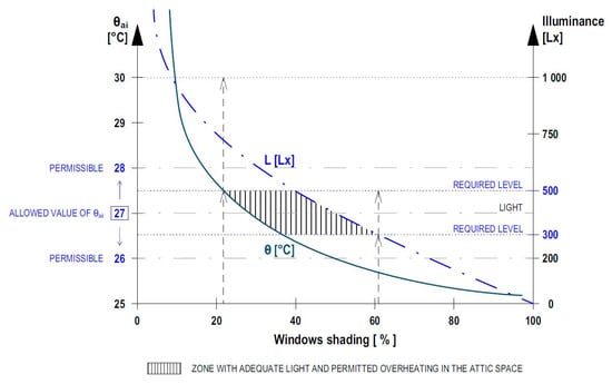
Figure 1.
Subject of solution.
In addition, non-residential and residential buildings represent very different evaluation scenarios, and it is not yet entirely clear whether one metric could apply to both [36].
Residential architecture is one of the largest market segments in construction. However, the attention it pays to the field of daylight simulation is surprisingly low. This raises the question of whether existing daylight metrics are suitable for home design. In [37], a critical check of current climate-based daylight metrics in the context of residential architecture is provided. It has been found that existing workflows often overlook relevant aspects of daylight in living spaces, such as daylight, seasonal availability of daylight, and access to direct sunlight. Therefore, the concept of a new annual climate-based assessment framework is being introduced to overcome these shortcomings. It is called the Daylight Residential Score. There are some dynamic metrics discussed in [38,39].
The simulation program offers many outputs, including: brightness surfaces, light intensity values and the distribution of the daylight factor on the working plane, as well as the animation of daylight/sunlight. Minimum and average lighting conditions for classrooms are defined in [40,41].
As previously mentioned, the content of this study builds on an already published article [1] where a case study showed how it is possible to combine daylight and overheating in the summer and search for optimization. The work was carried out using several variations in the placement of the skylights. This contribution will also be based on specific in situ measurements.
Overheating in the summer is a problem that has already been described by several authors. In his dissertation [42], the author Hofman discusses the problem of overheating in spaces under the roof. He is also the co-author of several publications devoted to this issue [43,44,45].
Internal heat gains can be a major component of a building’s total heat load in dwellings. As the main sources of internal profits, it can be classified according to the source [46] and the sensible and latent heat (evaporating heat).
2. Materials and Methods
This study is devoted to the optimization of daylighting and overheating in the summer climatic period in a selected area of a building’s attic. The space in this attic is a case study where measurements of daylight and temperature were carried out in the selected time period in the summer. Subsequently, based on the established marginal conditions, simulations of daylighting and overheating in the summer in a dynamic state of the environment were carried out and proposals for the prevention of overheating were considered. The activities were gradually implemented and are shown in a flowchart for clarity (Figure 2).
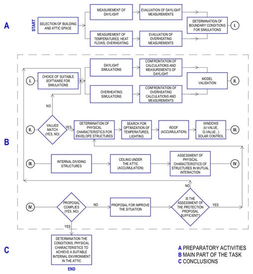
Figure 2.
Research methodology flowchart.
2.1. Calculations Methods
Daylight simulation, the calculation of summer thermal stability, and the properties of building structures are often examined using dynamic thermal characteristics. Studies that dealt with the calculation and comparison of structures using dynamic thermal characteristics mainly discuss the topicality and severity of the problem of thermal stability and thermal comfort within the indoor environment of buildings. The characteristics describing the thermal behavior of a structure during periodic changes of boundary conditions in the form of a sinusoid are more generally given in the standard ČSN EN ISO 13786 [47]. They are mainly used in the calculation of thermal stability in the summer [48]. The standard STN 73 0540 [49] does not stipulate a requirement for dynamic thermal characteristics of structures; therefore, it can only be used to compare structures with each other.
To compare the structures themselves, it is possible to proceed according to the standard STN 73 0540 [49]. This standard uses calculation programs in the assessment of 1D heat and moisture propagation. The resulting value is only informative as there is no mandatory requirement according to the standard STN 73 0540-2. Since the method assumes a time change of the boundary conditions as a harmonic oscillation, the response to the harmonic oscillation of the boundary conditions is also a harmonic oscillation. The relationships between the quantities on the surface m and n of the structure are expressed in matrix form according to t
where ^t is the phase harmonic change phasor and ^q is the phasor harmonic change heat flux density.
Complex elements of a transfer matrix change. The individual elements of the Zmn matrix are calculated according to the standard ČSN EN ISO 13786 [47]. The great advantage of matrix calculation is the simplicity in the calculation of multilayer structures, which we calculate simply using the matrix product.
where Zs is the matrix of boundary conditions and ZN is the matrix layer construction.
where Y11 is the dynamic heat admittance on the inner surface [W·m−2·K−1], Y22 is the dynamic heat admittance on the outer surface [W·m−2·K−1], and Y12 is the dynamic heat transfer [W·m−2·K−1].
It is possible to calculate important parameters to compare the thermal stability of the structure. This requires calculating the ratio between the complex amplitude of the heat flux density on the surface of the structure adjacent to zone m and the complex amplitude of the temperature in zone n, according to the literature:
where Ynm is dynamic heat transfers if n ≠ m [W·m−2·K−1] and dynamic heat admittance if n = m [W·m−2·K−1], including the complex amplitude of heat flux density on the surface, the structures adjacent to zone m [W·m−2], and the complex temperature amplitude in zone n.
The positive heat flux orientation is taken when it points from the surface into the structure. We further assume that zone n is the outdoor environment and zone m is the indoor environment. Ynm and Ynn are complex numbers, so each one describes an amplitude and phase shift. For this reason, two parameters can be derived from the dynamic heat transfer Ynm, namely the decrement factor and the corresponding time lag Δtf.
where Ynm is the dynamic heat transfer [W·m−2·K−1] and t U is the heat transfer coefficient [W·m−2·K−1].
where Ynm is the dynamic heat transfer [W·m−2·K−1] and T is the period of repetition (one day = 86,400 s) [s].
The attenuation factor describes the damping of the temperature wave that occurs when passing from the exterior to the interior, and the phase shift describes the corresponding delay. According to the literature [50], for thin light structures without thermal stability, the attenuation factor f approaches an infinitely large number, and the phase shift Δtf is zero. The position is similar on the inner surface, where we can again derive two parameters from the dynamic heat admittance Ynn, the amplitude of the heat admittance Y, and the corresponding phase shift (time lag) ΔtY relations
where Ynn is the dynamic heat admittance [W·m−2·K−1] and T is the period of repetition (one day = 86,400 s) [s].
These parameters show us how the structure reacts to changes in the heat flux density of the indoor environment and changes in the indoor environment temperature. According to the literature [51], the value of heat admittance Y is approaches the value of the heat transfer coefficient U for thin light structures without thermal stability and the phase shift Δty is zero.
These parameters depend very much on the properties of the inner layer. Therefore, if thermal insulation is placed on the inside of the wall, the heat admittance will be significantly affected.
In the summer, the thermal stability of the room is evaluated using the highest daily air temperature in the room θai,max. This temperature must be lower than the maximum temperature prescribed by the standard.
where θai,max is the highest daily air temperature in the room and θai,max N is the highest daily air temperature in the room according to the standard or prescriptions (26–28 °C). The recommended maximum temperature should not exceed 27 °C.
The optimal internal temperature for a person in an indoor environment depends on individual needs and other factors. According to these facts, the standard parameters of the indoor climate for premises with a long-term stay are:
- In the summer—from 26 to 28 °C;
- In the winter—from 20 to 24 °C.
The regulation states that the requirement in the summer should not exceed the standard indoor air temperature (27 °C in non-production areas) in Slovakia. Exceeding this value by a maximum of 2 °C for a maximum of 2 h is allowed by default, but only for apartment buildings.
2.2. Design of Envelope Structures to Improve Conditions
Regulating the overheating of exposed existing attic spaces is a challenging task in practice. However, on a theoretical level, there are approaches that could be applied in the project phase. Incident solar radiation can cause buildings to overheat in any climate if the building envelope is not designed to block unwanted solar gains, especially in the case of large transparent parts [52,53,54]. Measures to ensure shading are important in all four basic types of climates, and they are especially crucial in territories where the length and intensity of the cooling season dominates the heating season. However, shading systems also affect the daylighting of buildings. Improper coordination between the thermal and light effects of shading devices can result in visual discomfort and increased demands of artificial lighting.
One of the basic ways to provide shading is to design the shape of the building so that it casts shadows on its own transparent parts. The building can be shaped to prevent the penetration of direct solar radiation while the living rooms are illuminated by diffuse light from the sky. The shading is determined by the Shading Factor. The Shading Factor is the shaded fraction of the PV field with respect to the full sensitive area for a given sun orientation (values 0 = no shaded, 1 = fully shaded). The direct shading factor fB is defined as the ratio of the shaded area AS and the area of the module AM, as shown in Equation (10) [55]. When the shadow covers the module entirely, AS is equal to AM, and fB is 1. Contrarily, when there is no shadow, AS and fB are 0.
where fB is the direct shading factor, AS is the shaded area, and AM is the module.
In many cases, the use of external barrier shading is impossible due to building codes, architectural requirements, and design constraints. Therefore, the use of purpose-designed shading devices represents the most flexible and universal approach to shading transparent parts of the building envelope. Shading devices, or structures purposefully designed to reduce solar gains, are either fixed or movable. Fixed shading devices include overhangs, vertical elements, balconies, awnings, canopies, external blinds, Brise-soleil, light shelves, sun-control glazing, and recessed windows. Movable shading includes internal and external blinds, roller shades, shutters, and curtains. However, in this case study we do not consider a specific type of shading. We only consider the percentage of shading of transparent surfaces in general.
Windows partially determine the conditions of the internal climate of buildings based on their ratio to the area of the envelope. In the summer, the parameter of the transparent structure responsible for the transport of heat from the sun into the interior plays an important role in TSET or Total Solar Energy Transmittance. In the case of attic spaces, due to the influence of the slope of the roof and the roof windows, it is especially important to pay attention to their thermal–technical properties (including their heat transfer coefficient and their total solar energy transmittance) because the angle of the sun’s rays in the summer is more unfavorable from the point of view of overheating.
TSET describes the ability of a transparent structure to separate solar heat from solar radiation. It can be calculated as the sum of the direct solar transmittance τe and the secondary heat transfer qi of the transparent structure inwards. The secondary heat transfer results from the heat transfer caused by convection and from the long-wave infrared radiation of the part of the incident radiation that is absorbed by the glazing [51]:
where τe is direct solar transmittance and qi is the heat transfer of the transparent structure inwards.
Comparisons of the resulting thermal–technical parameters of (a) the original clear glass system, (b) the glass system with the proposed selective layer, (c) the glass system with a selective layer and sun protection, and (d) a glazing system with sun protection can be seen in Table 1.

Table 1.
Thermal properties of skylights (35°) and windows in the vertical plane (90°), including the Ug–heat transfer coefficient for glazing where g is the total solar energy transmittance.
Changing the thermal–technical properties of existing windows can also be achieved using the methods of window refurbishment [56], including methods that change the thermal–optical properties of the existing window in favor of the user’s requirements.
The authors addressed the mentioned issues in a different period of 2022. These include the problems of daylight optimization [57], environmental impact and IEQ [58], and multi-objective optimization in terms of energy load and daylight [59] or shading devices for naturally ventilated spaces [60].
3. Case Study
3.1. Chosen Building and Space
The subject of this study is the space located in the attic of a building that has been restored. The original older brick three-story building with a traditional truss is located in the northern part of the city of Košice in Slovakia (Figure 3).
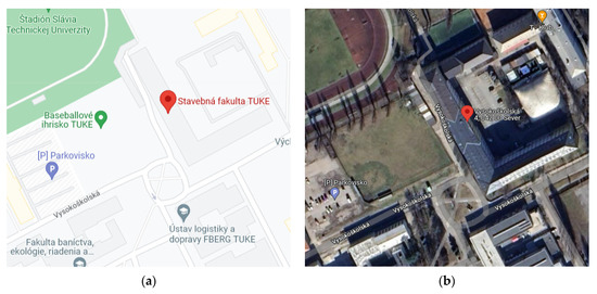
Figure 3.
The location of the building studied in this paper https://www.google.sk/maps/place/kosice (accessed on 22 September 2022). (a) A selected part of the Košice map (48.72°; 21.258056°) and (b) a view of the building from above.
A view of the building before and after the restoration and the selected spaces in the attic intended for assessment can be seen in Figure 4.
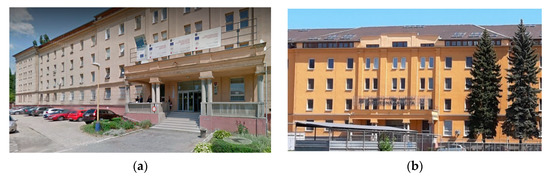
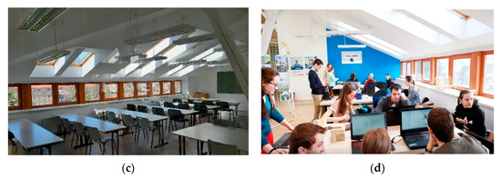
Figure 4.
The external and internal view of the selected building and the selected room in the attic space. (a) The building before reconstruction, (b) the building after reconstruction, (c) an empty room, and (d) a used room.
The roof was raised by 1.2 m during the restoration so that the spaces above the entire floor plan could be used. The original truss had masonry where the rafters were laid only 0.5 m above ceiling level. There were tie beams in the truss which did not create a suitable attic space. The reconstruction resulted in a new premises.
3.2. Evaluation of Measurements in Case Study Room
The realized measurement of the classroom in the attic space is from the summer of 2020. The space’s dimensions are 5.820 × 10.875 m (63.29 m2). The height of the space is 2.20 m at the envelope wall and 5.350 m at the top of the sloped roof. The composition of individual constructions is shown in Table 2. We measured parameters that include the internal microclimate air temperature (°C), the relative air humidity (%), the air flow rate (m/s), the surface temperatures (°C), and illuminances (l×). It can be seen in the floor plan (see Figure 5).
Table 2.
Composition of the envelope structures as a perimeter of closed space.
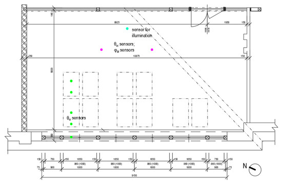
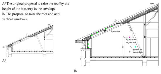
Figure 5.
The floor plan and section of space where the measuring devices were placed.
The measurements took place from May to October during very warm days. The maximum indoor temperatures were recorded in July. The goal was to monitor thermal comfort during the 10 warm days that occur from 15 July 2020 to 25 July 2020 and the 14 days from 28 August 2020 to 10 September 2020 when the results were the most pronounced. The selected period fulfilled its purpose perfectly because the weather was very clear and warm consistently which would cause thermal discomfort in terms of overheating in the chosen space. Occupants were not present in the room during the measurements. The primary goal was to correctly describe the external and exterior thermal load. Additional factors affecting the overall thermal comfort of the room are considered in the simulations in the next chapter. The mathematical model makes it possible to consider other factors very precisely and to examine their impact on the thermal comfort of the room in terms of overheating in the mentioned periods.
Outdoor climate conditions in Košice can be seen in Figure 6. Meteoblue climate diagrams are based on 30 years of hourly weather model simulations and are available for every location on Earth at https://www.meteoblue.com/sk (accessed on 21 September 2022). They provide good data about typical climate patterns and expected conditions (including temperature, precipitation, sunshine, and wind).
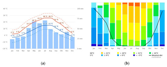
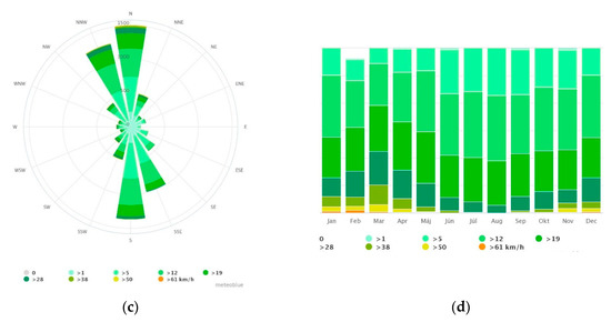
Figure 6.
Basic climate data for the city of Košice (48.72°; 21.258056°). (a) Average temperatures and total precipitation (“average daily maximum” (solid red line) shows the maximum temperature of an average day in each month for the city of Košice. Conversely, “average daily minimum” (solid blue line) shows the average minimum temperature. Hot days and cold nights (dashed red and dashed blue line) show the average of the hottest days and coldest nights in each month over the past 30 years), (b) highest temperatures, (c) wind rose, and (d) wind speed. https://www.meteoblue.com/sk/po%C4%8Dasie/historyclimate/climatemodelled/ko%c5%a1ice_slovensk%c3%a1-republika_724443 (accessed on 21 September 2022).
Simulated weather data have a spatial resolution of approximately 30 km and may not reproduce all local weather effects, such as thunderstorms, local winds, and tornadoes, or the local variations that occur in urban, mountainous, and coastal areas. The hourly historical weather data for the location of Košice based on a 30-year period was created using the history + service. Various factors, such as temperature, wind, cloudiness, or precipitation, are in CSV format.
Average temperatures and total precipitation can be seen in Figure 6a, and the highest temperatures in Košice are shown in Figure 6b. Figure 6b shows that there are 12 tropical days during the year (or days when the maximum temperature exceeds 30 °C). The “average daily maximum” (solid red line) shows the maximum temperature of an average day in each month for Košice. The wind speed can be seen in Figure 6d, and the veteran rose (Figure 6c) indicates the predominant north–south wind directions in Košice.
As for the methodology of measuring the aforementioned parameters of the indoor microclimate (Figure 7), two measuring stations, i.e., two measuring sets, were used. The first measuring set intended to monitor the illuminance of the working plane of the bench using a photoelectric cell. At the same time, sensors for monitoring air temperature, relative air humidity, and air flow rate were included in this set. The photoelectric cell used one pc. placed on the table at a height of approx. 1 m above the floor. Another sensor was used and included 2 pcs. in two places in the room at a height of 2 m above the floor. The resulting measured temperature and relative humidity are considered as the average of the measured values of these two sensors. The second measuring set consisted of a control panel and sensors that were used to measure the surface temperature on the transparent structures. The room has two rows of slanted wooden roof windows in the plane of the roof and one row of vertical wooden windows in the plane of the facade. The temperature was measured using one section of the windows in the plane of the facade and the roof’s surface of the frame and the surface of the glass. The entire measurement took place together with the preparatory measurement for debugging and setting the methodology from mid-April to mid-October. A shorter section was chosen for data evaluation and for the purposes of this article (28 August to 10 September 2020).
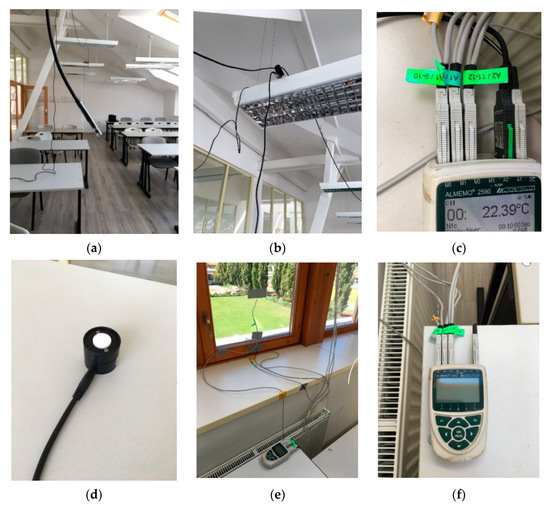
Figure 7.
Views of the placed measuring devices which measured surface temperatures, heat flux densities, lighting, and microclimate conditions. (a) sensor for recording the internal air temperature (b) recording the temperature and relative humidity at the height of the lamps (c) view of the sensor connection to the ALMEMO recorder (d) photo sensor for recording illumination (e) recording surface temperatures on vertical windows (f) view of connecting the sensors to the recorder.
Outdoor air temperature and relative humidity were measured using Ahlborn equipment sets (relative humidity and air temperature sensor Almemo FHAD46C0, Lighting intensity sensor Almemo FLAD03VL1, and dataloggers Almemo 2590). Photo documentation of the measurement process is shown in Figure 7.
Results of the temperature measurement of indoor air conditions in analyzed time can be seen in Figure 8.
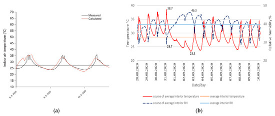
Figure 8.
Temperature measurement results in the realized time from 28 August 2020 to 10 September 2020. (a) the measured and calculated internal air temperatures during model verification—the closest approximation of the calculated and measured data 8–10 September 2020; (b) measured data during the entire interval, average daily temperatures and average relative humidity of the indoor air.
The validation of the simulation model was carried out during the measurement period between 28 August 2020 to 10 September 2020. It was not possible to correct the model based on the reference data (reference year) because the measurements took place under specific conditions for the given period and are unique and unrepeatable conditions for the given space, i.e., the classroom. A short time was chosen to debug the measured parameters. The measurement was performed only as a control. There was a lot of information missing regarding operation, rooms during measurements, window ventilation, air infiltration, opening doors, etc. A lot of information was missing regarding the complex reasoning of the outdoor climate. Even so, it was possible to find a short “correlation” between the measured indoor air temperatures and the simulated values based on the assumed boundary conditions. The simulation calculation of lighting (illuminance) and overheating (indoor air temperature) was performed only as a means of comparing cases one through twelve. A comparison of the measured and simulated temperatures closest to A/ and the measured values of internal temperatures B/ can be seen in Figure 8.
From the given data, it can be concluded that measured values were min θai = 23.3 °C, average θai = 28.7 °C, max θai = 38.7 °C, and average ϕi = 46.3%.
3.3. Daylight Evaluation
Results of illuminance measurements in realized time from 28 August 2020 to 10 September 2020 can be seen in Figure 9.
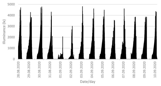
Figure 9.
Illumination intensity values at the considered measurement time in the chosen classroom.
To reduce overheating, various elements are used that ensure shading, such as blinds, curtains, etc. In our case, external blinds were chosen, and shading from 10 to 90% was calculated (or a direct shading factor 0.1–0.9).
The results of illumination at individual distances from vertical windows (1.0, 2.2, and 3.4 m) can be seen in Figure 10.
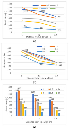
Figure 10.
Shading vertical windows and skylights of the building. (a) Shading vertical windows and skylights, (b) shading only skylights, and (c) shading vertical windows and skylights.
The change in illumination due to the shading of roof and vertical windows can be seen in the images obtained by simulation of illumination. This fact can be seen in Figure 11. Calculations of daytime illumination of a network of nine points for individual cases of shading were carried out. The value of the light transmission coefficient T varied according to the shading factor f.
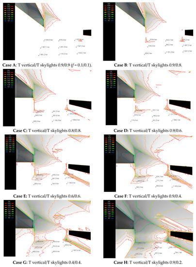
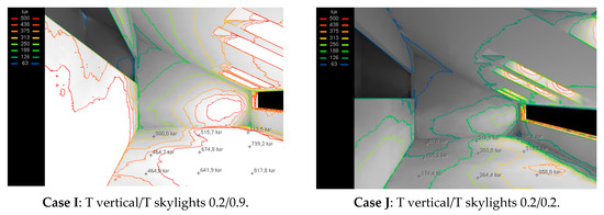
Figure 11.
Results of illuminance simulations for cases A–J (for Cases 1–12, see the figure in Section 4).
In Figure 12, it can be seen that there is a reduction of illumination due to the shading of the windows.
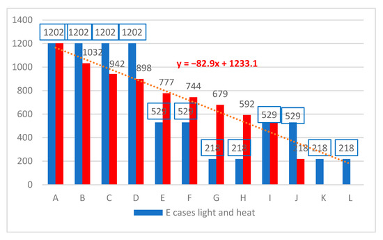
Figure 12.
Reduction of illumination due to shading vertical windows and skylights (red columns) and scenarios for comparison light and overheating (blue columns).
3.4. Evaluation of Overheating
The simulation calculation was carried out using the WUFI Plus tool. The model of the analyzed part of the building is shown in Figure 13.
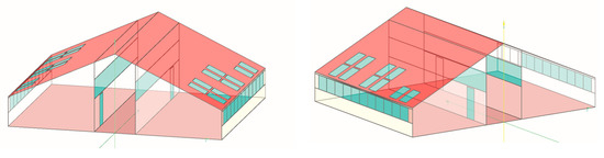
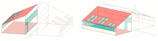
Figure 13.
Model of the analyzed part of the building (the space in the attic).
A room with a north-west orientation and a floor area of 63.3 m2 (with an inner volume of the room of 125.0 m3) was selected to assess overheating.
IWEC climatic parameters for Košice (48.72°; 21.258056°) were used as the boundary conditions for simulation.
- https://www.ashrae.org/ (accessed on 10 September 2022)
- (http://www.equaonline.com/ice4user/indexIWEC.html#s) (accessed on 10 September 2022).
The simulated time for all calculation cases was from 1 May 2020 to 10 October 2020 in a time interval of 1 h, i.e., 3889 h. The results of the boundary conditions for the simulations are shown as outdoor temperature curves and solar radiation for all periods and the chosen 10 day period. They can be seen in Figure 14.
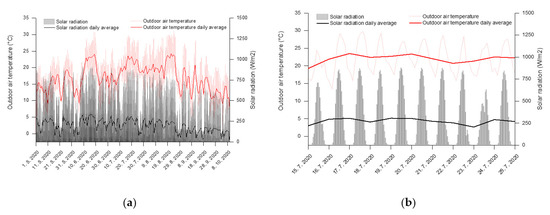
Figure 14.
Final graphs for the boundary conditions of the calculation. (a) is the entire observed period, i.e., from 1 May 2020 to 10 October 2020 and then (b) the selected period of the hottest days from 15 to 25 July 2020.
The description of computational simulations 1–8 and cases 9–12 (air exchange at nighttime) can be seen in Table 3.
Table 3.
Description of individual calculation cases (case studies) for simulation.
The calculated course of indoor air temperatures for simulation scenarios Case 1 to Case 12 in a north-west-facing classroom for the whole simulated time are shown as a course of temperatures and can be seen in Figure 15. The simulation calculation was carried out using the WUFI Plus tool. www.wufi.de. It considered clo = 0.61 (or trousers and a long-sleeved shirt) for calculation.
Figure 15.
Results for the entire evaluation time from 1 May 2020 to 10 October 2020 and the 10 hottest days from 15 July 2020 to 25 July 2020 above the window shading (Cases 1–12). (a) is the entire observed period, i.e., from 1 May 2020 to 10 October 2020 and then (b) the selected period of the hottest days from 15 to 25 July 2020 for all 12 case studies.
Figure 16 shows the calculated course of average temperatures of the dividing structure based on a light sandwich structure (Case 1) and a heavy reinforced concrete wall (Case 2) for the aforementioned total simulated time and for the selected time period from 15 July 2020 to 25 July 2020 (241 h).
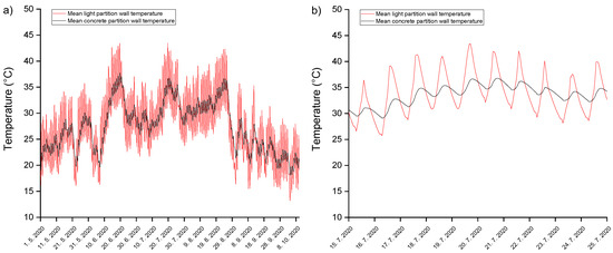
Figure 16.
Results for the entire evaluation time 1 May 2020 to 20 October 2020 and 15 July 2020 to 25 July 2020 for Cases 1 and 2 (heavy and light partitions). (a) Whole period (b) The hottest days.
The given figure shows the shift in the temperature amplitudes for Cases 1 and 2. From the graphs, it is also possible to see the “sensitivity” of the light wall structure to changes in temperature, which changes rapidly (or has a short phase shift) compared to the heavy reinforced concrete dividing structure. In Cases 1 and 2, the results are interesting. It can be deduced from the picture that the heavier reinforced concrete wall subsidizes the interior space with radiated heat at night and in the evening.
Figure 17 shows the displayed box plot of indoor air temperatures for all simulation scenarios. During the analyzed period, the average value of the internal air temperature was 33.2 °C, with a minimum of 23.9 °C and a maximum of 45.9 °C. This was based on the original condition without window tinting. By replacing the dividing structure with a heavy one (Case 2), the maximum calculated air temperature was reduced to a value of 41.3 °C. However, the minimum air temperature at night was less favorable (25.3 °C), which had only a minimal effect on the average air temperature. When using the thermal insulator with a higher volumetric weight in Case 3, temperature peaks during the day in the interior were reduced to 42.8 °C, and the average air temperature did not rise above 33 °C. In the case of a combination of a heavy dividing structure and a thermal insulator with a higher volumetric weight, i.e., Case 4, the temperature maximum during the simulated time reduced below 40 °C, while the average indoor air temperature reached the most favorable value among the analyzed cases without window shading (Cases 1–4).
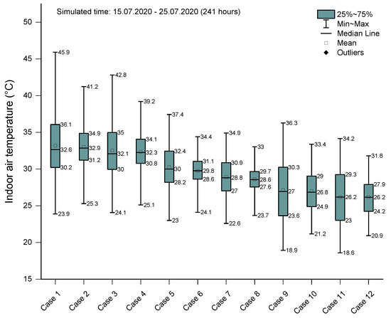
Figure 17.
Cases 1–12 for 10-day high solar radiation period 15 July 2020 to 25 July 2020 for Cases 1 and 2 (heavy and light partitions).
In the case of shading the skylights, the calculated temperatures of the internal air significantly reduced. For the shading of the skylights of the original alternative (Case 1) with 90% dark shading and Case 5, the maximum temperature was 37.4 °C, and the minimum was 22.3 °C, with an average value just above 30 °C. When we shaded the skylights in Case 4, we reduced the maximum indoor air temperature to below 35 °C. Heavier partition wall components and heavier thermal insulation in the roof caused less efficient cooling at night. Constructions were accumulated by heat. This effect manifested in a higher temperature minimum compared to the previous case (Case 5). The lowest value of the temperature minimum was calculated for Case 7, and it was 22.6 °C. It should be noted here that the permitted temperature of 27 °C (plus or minus two degrees) was not reached in the attic.
4. Discussion
Calculations (simulations) were carried out for the given room between 15 July 2020 and 25 July 2020. Shades from Case 1 (0.9 vertical and 0.9 skylights) to Case 8 (0.2 vertical and 0.2 skylights [roof]) windows did little to reduce internal temperature. It was noticeable when the sun shines, but it was very slow when the outside temperature dropped.
From the resulting graph (see Figure 18), it can be seen that for each variant of the calculation (Cases 1–8), the maximum temperature decreased from 45.9 to 33.0 °C (29%), but the average internal temperature decreased only from 26.5 °C to 24.4 °C (8%). Therefore, night ventilation was taken into account during the calculation, i.e., the windows were left open overnight and all the air was exchanged. This also cooled the dividing and perimeter walls, and in the morning, when the windows were closed again, the cold accumulated structures maintained a cooler environment. This is especially evident at T 75% (green line), i.e., 75 percent of all detected internal temperatures were below the required value of 27 °C, which we failed to observe in previous cases. In all considered cases, Case 1 to Case 8, this value was above 27 °C.
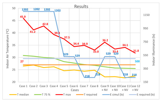
Figure 18.
Results daylighting and overheating in attic space Case 1 to Case 12.
Although the maximum air temperature reached seemed to be 33 °C to 35 °C, it was always lower than in the previous cases. This was at the expense of the fact that the value of the average illuminance decreased in all the latter cases to the level of 529 or 218 lx. However, it was more than the required minimum of 100 lx. In places near the vertical windows, values higher than 500 lx were reached because there was a superposition of light fluxes from above and from the side.
The resulting state from the last four cases where night cooling was considered led to the optimization of the design of the interior environment in the attic. This state cannot be achieved using buildings alone. If the storage capacity of dividing structures is increased by increasing the specific volume, weight, and heat capacity of selected materials, it cannot be realized without limits. That would disrupt the statics, or the creation of such a space would be very challenging from a static point of view. The regulations allow the prescribed indoor air temperature to exceed 27 °C by 2 °C for several hours per day, which means that the indoor temperature should not be higher than 29 °C for several hours. As we can see, this fact cannot be achieved even with night cooling. Therefore, such cases of overheating attic spaces cannot be solved by only addressing the structures themselves, and environmental technology will be helpful (i.e., the mechanical treatment of indoor air, such as air conditioning and possibly ventilation).
5. Conclusions
The problem of overheating spaces under a sloping roof in the attic is ongoing. Many authors have studied this issue. They came to different conclusions. Considering the attractiveness of these spaces and the possibility of using old uninhabited attic spaces in historical parts of cities, it is necessary to focus on creating a suitable interior space for users. Of course, there will always be a certain percentage of unsatisfied people, but the regulations and marginal conditions for designing building structures allow the majority of residents to feel comfortable in the interior. In winter, this problem is not as pronounced. Due to the insufficient level of accumulation of structural elements from which the building structures of the attic are created, there is a risk of excessive overheating in the summer.
The space chosen for the research was an attic that was not originally used. After the restoration of the building, the attic was raised by approx. 1.2 m. Since it is a building in the center of the city, the attractiveness of its improved usability is great. This space, compared to others that were subjected to research, is specific in that it is illuminated by vertical (connected) windows and skylights on two levels in the roof planes.
The city of Košice, where the building is located, is in the central part of Europe where the climate is continental. It is located at approximately 49 degrees north latitude where winters are cold and summers are warm.
From the total annual period, the period from 1 May 2020 to 10 October 2020 was chosen. For a closer assessment, the 10 hottest days of the year were chosen, from 15 July 2020 to 25 July 2022. Measurements were compared with calculations, and after model validation, several variants of roof and vertical window shading were simulated. Interesting conclusions emerged from the solution.
We tried to theoretically replace the roof shell and internal dividing structures with structural elements that have greater heat accumulation, but the results did not lead to the allowed values of overheating.
With the heaviest constructions (what the building can withstand statically) and the greatest shading, the internal temperature decreased, but it still did not reach the required level of 27 °C.
Lighting is not a problem because even with the greatest shading, which is 90% shading of the verticals and skylights, the minimum level of internal lighting is achieved, which is 100 lx in current regulations.
It is worse with the internal temperature, which is 45.9 °C compared to the first variant with a minimum temperature of 31.8 °C, indicating an unsatisfactory condition.
The maximum temperature in the attic drops by only 31% compared to unshaded windows if both vertical and roof windows are shaded using external blinds.
The minimum air temperature reached in the attic drops by 26%.
Even though the standard says that the indoor temperature of residences with human occupants should not exceed 27 °C in the summer, this maximum can be exceeded by two degrees for several hours per day. This means people should tolerate a temperature of 29 °C for one or two hours per day. This required level is reached only in some cases at T 75%.
On the hottest days, even if we use night ventilation (if the layout of the building allows it), we cannot reach an internal temperature below 29 °C.
When measurements are taken at the end of summer, when the outside temperature is lower, the indoor maximum temperature is around 39 °C, the lowest is around 23 °C, and the average is around 25 °C.
The percentage decrease in illuminance is more significant than the decrease in the maximum temperature due to overheating.
In conclusion, it is necessary to state that further attention should be paid to this issue. It is known that the required parameters can be achieved by combining the creation of suitable building structures with necessary accumulation, window shading, external reflective surfaces, and environmental technology (i.e., ventilation and artificial ventilation and air conditioning).
Author Contributions
Conceptualization and methodology—D.K., E.D. and M.V.; software validation—E.D., M.V. and S.Z.; formal analysis and data curation—K.H., S.Z. and Z.D.; writing—original draft—D.K.; writing review and editing—D.K., E.D. and M.V.; investigation—D.K.; resources—S.Z., K.H. and Z.D.; supervision and project administration—D.K., E.D. and M.V. All authors have read and agreed to the published version of the manuscript.
Funding
This research was funded by the research project VEGA 1/0626/22 and VEGA 2/0017/20 of the Scientific Grant Agency, the Ministry of Education, Science, and Research, and Sport of the Slovak Republic and the Slovak Academy of Sciences.
Data Availability Statement
Not applicable.
Conflicts of Interest
The authors declare no conflict of interest.
References
- Dolnikova, E.; Katunsky, D.; Vertal, M.; Zozulak, M. Influence of Roof Windows Area Changes on the Classroom Indoor Climate in the Attic Space: A Case Study. Sustainability 2020, 12, 5046. [Google Scholar] [CrossRef]
- Gupta, A.; Thakur, H. The Study of Parametric Factor in Attic Space for Winter Season. IOP Conf. Ser. Mater. Sci. Eng. 2019, 691, 12091. [Google Scholar] [CrossRef]
- Ge, H.; Wang, R.; Baril, D. Field measurements of hygrothermal performance of attics in extreme cold climates. Build. Environ. 2018, 134, 114–130. [Google Scholar] [CrossRef]
- Wang, R.; Ge, H.; Baril, D. Moisture-safe attic design in extremely cold climate: Hygrothermal simulations. Build. Environ. 2020, 182, 107166. [Google Scholar] [CrossRef]
- Richter, J.; Staněk, K.; Tywoniak, J.; Kopecký, P. Moisture-safe cold attics in humid climates of Europe and North America. Energies 2020, 13, 3856. [Google Scholar] [CrossRef]
- Forest, T.W.; Walker, I.S. Attic Ventilation and Moisture; Canada Mortgage and Housing Corporation: Ottawa, ON, Canada, 1993. [Google Scholar]
- Chwieduk, D.A. Solar energy impact on space heating and cooling needs in moderate climate. IOP Conf. Ser. Mater. Sci. Eng. 2018, 415, 12008. [Google Scholar] [CrossRef]
- Parker, D.S.; Sherwin, J.R. Comparative summer attic thermal performance of six roof constructions. Trans.-Am. Soc. Heat. Refrig. Air Cond. Eng. 1998, 104, 1084–1092. [Google Scholar]
- Fantucci, S.; Serra, V. Investigating the performance of reflective insulation and low emissivity paints for the energy retrofit of roof attics. Energy Build. 2019, 182, 300–310. [Google Scholar] [CrossRef]
- Lee, S.W.; Lim, C.H. Reflective thermal insulation systems in building: A review on radiant barrier and reflective insulation. Renew. Sustain. Energy Rev. 2016, 65, 643–661. [Google Scholar] [CrossRef]
- Piotrowski, J.Z.; Stroy, A.; Olenets, M. Mathematical model of the thermal-air regime of a ventilated attic. J. Civ. Eng. Manag. 2015, 21, 710–719. [Google Scholar] [CrossRef]
- Bečkovský, D.; Ostrý, M.; Kalábová, T.; Tichomirov, V. Thermal stability of attic spaces with integrated PCMs during the climatic year. Adv. Mater. Res. 2013, 649, 175–178. [Google Scholar] [CrossRef]
- Elarga, H.; Fantucci, S.; Serra, V.; Zecchin, R.; Benini, E. Experimental and numerical analyses on thermal performance of different typologies of PCMs integrated in the roof space. Energy Build. 2017, 150, 546–557. [Google Scholar] [CrossRef]
- Li, H.; Li, J.; Xi, C.; Chen, W.; Kong, X. Experimental and numerical study on the thermal performance of ventilated roof composed with multiple phase change material (VR-MPCM). Energy Convers. Manag. 2020, 213, 112836. [Google Scholar] [CrossRef]
- Roberts, B.M.; Allinson, D.; Diamond, S.; Abel, B.; Bhaumik, C.D.; Khatami, N.; Lomas, K.J. Predictions of summertime overheating: Comparison of dynamic thermal models and measurements in synthetically occupied test houses. Build. Serv. Eng. Res. Technol. 2019, 40, 512–552. [Google Scholar] [CrossRef]
- Laouadi, A.; Bartko, M.; Lacasse, M.A. A new methodology of evaluation of overheating in buildings. Energy Build. 2020, 226, 110360. [Google Scholar] [CrossRef]
- Tink, V.; Porritt, S.; Allinson, D.; Loveday, D. Measuring and mitigating overheating risk in solid wall dwellings retrofitted with internal wall insulation. Build. Environ. 2018, 141, 247–261. [Google Scholar] [CrossRef]
- Birchmore, R.; Davies, K.; Etherington, P.; Tait, R.; Pivac, A. Overheating in Auckland homes: Testing and interventions in full-scale and simulated houses. Build. Res. Inf. 2017, 45, 157–175. [Google Scholar] [CrossRef]
- Roberts, B.M.; Allinson, D.; Lomas, K.J. Evaluating methods for estimating whole house air infiltration rates in summer: Implications for overheating and indoor air quality. Int. J. Build. Pathol. Adapt. 2021. [Google Scholar] [CrossRef]
- Bullová, I.; Kapalo, P.; Katunský, D. Quantification of air change rate by selected methods in a typical apartment building. Buildings 2021, 11, 174. [Google Scholar] [CrossRef]
- Psomas, T.; Heiselberg, P.; Lyme, T.; Duer, K. Automated roof window control system to address overheating on renovated houses: Summertime assessment and intercomparison. Energy Build. 2017, 138, 35–46. [Google Scholar] [CrossRef]
- Stejskalová, K.; Vavřínová, N. Assessment of the Summer Thermal Stability of the Attic Room Using Two Different Software. Civ. Environ. Eng. 2020, 16, 360–369. [Google Scholar] [CrossRef]
- Wang, J.; Norbäck, D. Subjective indoor air quality and thermal comfort among adults in relation to inspected and measured indoor environment factors in single-family houses in Sweden-the BETSI study. Sci. Total Environ. 2022, 802, 149804. [Google Scholar] [CrossRef]
- Nepomuceno, M.C.; Martins, A.M.; Pinto, H.A. A Comparison between On-Site Measured and Estimated Based Adjustment Factor Values Used to Calculate Heat Losses to Unconditioned Spaces in Dwellings. Buildings 2022, 12, 146. [Google Scholar] [CrossRef]
- Zazzini, P.; Capone, M. Energy Efficiency Improvements in Historic Buildings: Analysis of a Case Study in Central Italy in: IIETA Modelling, Measurement and Control B. IIETA 2018, 87, 135–142. [Google Scholar]
- Ozarisoy, B. Energy effectiveness of passive cooling design strategies to reduce the impact of long-term heatwaves on occupants’ thermal comfort in Europe: Climate change and mitigation. J. Clean. Prod. 2022, 330, 129675. [Google Scholar] [CrossRef]
- Lei, M.; van Hooff, T.; Blocken, B.; Pereira Roders, A. The predicted effect of climate change on indoor overheating of heritage apartments in two different Chinese climate zones. Indoor Built Environ. 2022, 31, 1420326X221085861. [Google Scholar] [CrossRef]
- Watson, D. Bioclimatic design. In Sustainable Built Environments; Springer U.S.: New York, NY, USA, 2020; pp. 19–41. [Google Scholar]
- Tywoniak, J.; Calta, V.; Staněk, K.; Novák, J.; Maierová, L. The application of building physics in the design of roof windows. Energies 2019, 12, 2300. [Google Scholar] [CrossRef]
- Li, X.; Taylor, J.; Symonds, P. Indoor overheating and mitigation of converted lofts in London, UK. Build. Serv. Eng. Res. Technol. 2019, 40, 409–425. [Google Scholar] [CrossRef]
- Sungsoontorn, S.; Nonthiworawong, D.; Rattanadecho, P.; Prommas, R. Experimental investigation of attic heat gain reduction and indoor illuminance using a light-vent pipe. Int. J. Heat Technol. 2019, 37, 1171–1179. [Google Scholar] [CrossRef]
- Rissetto, R.; Pont, U.; Mahdavi, A. Performance comparison of timber-based assemblies and other construction solutions for rooftop extensions. Int. Rev. Appl. Sci. Eng. 2018, 9, 153–161. [Google Scholar] [CrossRef]
- Caffagni, E.; Libbra, A.; Muscio, A.; Tarozzi, L. A Pitched Roof with Forced Ventilation to Limit Solar Gains. Adv. Civ. Eng. Technol. 2018, 1, 1–3. [Google Scholar]
- Lomas, K.J. Summertime overheating in dwellings in temperate climates. Build. Cities 2021, 2, 487–494. [Google Scholar] [CrossRef]
- Katunský, D.; Brausch, C.; Purcz, P.; Katunská, J.; Bullová, I. Requirements and opinions of three groups of people (aged under 35, between 35 and 50, and over 50 years) to create a living space suitable for different life situations. Environ. Impact Assess. Rev. 2020, 83, 106385. [Google Scholar] [CrossRef]
- Mardaljevic, J.; Andersen, M.; Roy, N.; Christoffersen, J. Daylighting Metrics for Residential Buildings (No. CONF). 2011. Available online: https://infoscience.epfl.ch/record/166212 (accessed on 22 September 2022).
- Dogan, T.; Park, Y.C. A critical review of daylighting metrics for residential architecture and a new metric for cold and temperate climates. Light. Res. Technol. 2019, 51, 206–230. [Google Scholar] [CrossRef]
- Tregenza, P.; Sharples, S. Daylight Algorithms; IEA Task 21, Subtask C2—New Daylight Algorithms; School of Architecture, University of Sheffield: Sheffield, UK, 1995. [Google Scholar]
- Kittler, R.; Darula, S. Determination of time and sun position system. Sol. Energy 2013, 93, 72–79. [Google Scholar] [CrossRef]
- STN 730580; Daylighting in Buildings, Part–1 Basic Requirements, 1986 Part 2; Daylighting of Residential Buildings. Slovak Republic Oce of Standards, Metrology and Testing: Bratislava, Slovakia, 2000.
- EN 12464-1:2012; Light and Lighting; Lighting of Work Places-Part 1: Indoor Work Places. Slovak Republic Office of Standards, Metrology and Testing: Bratislava, Slovakia, 2012.
- Hofman, P. Analysis of Influence of a Roof Construction on Indoor Thermal Stability in Summer Season. Ph.D. Thesis, Brno University of Technology, Brno, Czech Republic, 2021. [Google Scholar]
- Altan, H.; Mohelnikova, J.; Hofman, P. Thermal and daylight evaluation of building zones. Energy Procedia 2015, 78, 2784–2789. [Google Scholar] [CrossRef]
- Potůčková, M.; Hofman, P. Comparison of quality measures for building outline extraction. Photogramm. Rec. 2016, 31, 193–209. [Google Scholar] [CrossRef]
- Hofman, P.; Potůčková, M. Roof type determination from a sparse laser scanning point cloud. AUC GEOGRAPHICA 2017, 47, 35–39. [Google Scholar]
- Energy-Models.com|TRACE 700, eQuest Training, EnergyPlus &LEED, Energy Modeling Support and Discussion Forum. INTERNAL HEAT GAINS (IHG)|Energy-Models.com [online]. Chicago: THOMAS, Varkie, c2010–2013. Available online: https://energy-models.com/internal-heat-gains-ihg (accessed on 22 September 2022).
- ČSN EN ISO 13786; Tepelne Chovani Stavebnich Dilců—Dynamicke Tepelne Charakteristiky—Vypočtove Metody. Uřad Pro Technickou Normalizaci, Metrologii a Statni Zkušebnictvi: Praha, Czech Republic, 2018.
- STN 73 4301; Dwelling Buildings. Slovak Republic Office of Standards, Metrology and Testing: Bratislava, Slovakia, 2005.
- STN 73 0540-2+Z1+Z2; Thermal Protection of Buildings. Thermal Performance of Buildings and Components. Part 2: Functional requirements; Slovak Republic Office of Standards. Metrology and Testing: Bratislava, Slovakia, 2019.
- Aste, N.; Angelotti, A.; Buzzetti, M. The influence of the external walls thermal inertia on the energy performance of well insulated buildings. Energy Build. 2009, 41, 1181–1187. [Google Scholar] [CrossRef]
- EN 410:2011; Glass in Building—Determination of Luminous and Solar Characteristics of Glazing. European Standard: Brussels, Belgium, 2011.
- Bellia, L.; Marino, C.; Minichiello, F.; Pedace, A. An overview on solar shading systems for buildings. Energy Procedia 2014, 62, 309–317. [Google Scholar] [CrossRef]
- Méndez Echenagucia, T.; Capozzoli, A.; Cascone, V.; Sassone, M. The early design stage of a building envelope: Multi-objective search through heating, cooling and lighting energy performance analysis. Appl. Energy 2015, 154, 577–591. [Google Scholar] [CrossRef]
- Košir, M.; Gostiša, T.; Kristl, Z. Influence of architectural building envelope characteristics on energy performance in Central European climatic conditions. J. Build. Eng. 2018, 15, 278–288. [Google Scholar] [CrossRef]
- Silva, M.; Roberts, J.J.; Prado, P.O. Calculation of the Shading Factors for Solar Modules with MATLAB. Energies 2021, 14, 4713. [Google Scholar] [CrossRef]
- Bizonova, S. Thermal-Optical Properties of Progressive Window Structures. Ph.D. Thesis, Technical University of Košice, Košice, Slovakia, 2021; p. 136. [Google Scholar]
- Mangkuto, R.A.; Koerniawan, M.D.; Hensen, J.L.; Yuliarto, B. Optimization of Daylighting Design Using Self-Shading Mechanism in Tropical School Classrooms with Bilateral Openings. J. Daylighting 2022, 9, 117–136. Available online: https://solarlits.com/jd/9-117 (accessed on 22 September 2022).
- Mastellone, M.; Ruggiero, S.; Papadaki, D.; Barmparesos, N.; Fotopoulou, A.; Ferrante, A.; Assimakopoulos, M.N. Energy, Environmental Impact and Indoor Environmental Quality of Add-Ons in Buildings. Sustainability 2022, 14, 7605. [Google Scholar] [CrossRef]
- Fan, Z.; Liu, M.; Tang, S. A multi-objective optimization design method for gymnasium facade shading ratio integrating energy load and daylight comfort. Build. Environ. 2022, 207, 108527. Available online: https://www.sciencedirect.com/science/article/pii/S0360132321009227 (accessed on 22 September 2022). [CrossRef]
- Yusoff WF, M.; Shaharil, M.I.; Mohamed, M.F.; Rasani, M.R.M.; Sapian, A.R.; Dahlan, N.D. Review of openings with shading devices at naturally ventilated buildings. Archit. Eng. Des. Manag. 2022, 18, 1–17. Available online: https://www.tandfonline.com/doi/abs/10.1080/17452007.2022.2095553 (accessed on 22 September 2022). [CrossRef]


Publisher’s Note: MDPI stays neutral with regard to jurisdictional claims in published maps and institutional affiliations. |
© 2022 by the authors. Licensee MDPI, Basel, Switzerland. This article is an open access article distributed under the terms and conditions of the Creative Commons Attribution (CC BY) license (https://creativecommons.org/licenses/by/4.0/).