Article

Multi-Objective Energy Optimal Scheduling of Multiple Pulsed Loads in Isolated Power Systems

1
State Grid Economic Technology Research Institute Co., Ltd., Beijing 102209, China
2
Department of Electrical Engineering, Xi’an Jiaotong University, Xi’an 710049, China
*
Author to whom correspondence should be addressed.
Sustainability 2022, 14(23), 16021; https://doi.org/10.3390/su142316021
Submission received: 29 October 2022 / Revised: 27 November 2022 / Accepted: 28 November 2022 / Published: 30 November 2022
(This article belongs to the Special Issue Sustainable Electric Power Systems: Design, Analysis and Control)

Abstract

:
Isolated power systems (IPS) usually have multifaceted operational objectives in engineering scenarios, and many key tasks are performed by multiple pulsed loads. The research on multi-objective energy optimal scheduling in isolated power systems which contain multiple pulsed loads is the subject of this paper. In addition, optimal mobility and maximum multiple pulsed load performance value are discussed. By introducing the concept of ship speed at the end state, isolated power system maneuverability is properly characterized by the final state ship speed, combined with the maximum efficiency of multiple pulsed loads, and a multi-objective optimization model of weighted form is constructed using a general, given solution method. In addition, two specific solutions regarding typical engineering scenarios are proposed in this paper: accelerating the catch-up situation and accelerating the evacuation situation. Algorithms for general situations and specific solutions regarding typical engineering scenarios are proposed. Study cases regarding specific engineering scenarios are demonstrated to verify the correctness and efficiency of the method. Finally, the limitations and shortcomings of the established methodology are emphasized.

1. Introduction

1.1. Motivation

Isolated power systems (hereinafter referred to as IPS) often operate in an environment where devices are frequently accessed and exited, and the topology is flexible [1,2,3,4,5,6]. In addition, when multiple special types of pulsed loads are connected to the IPS, system energy optimization scheduling will face greater challenges.
The IPS is often in the following three modes of operation when performing tasks: normal mode, emergency mode and suppression mode [4]. Each mode corresponds to a different running scenario. In these different scenarios, the actual ship’s concern will change between maneuverability and resilience. In one scenario, an IPS may focus on a single goal, or it may focus on two or more goals. Multi-objective energy optimal scheduling in IPS is the main concern of this paper.

1.2. Related Works

As described in [1], due to the high energy density of the pulsed load, in order to reduce the energy impact caused by the frequent switching of the pulsed load and avoid the transient instability of the system, the pulsed load generally has an energy storage device. Specifically, at a common connection point where the pulsed load is connected to the power grid, an energy storage device such as a supercapacitor or a flywheel can be installed, and the energy required for the pulsed load operation can be obtained by charging the energy storage device. After charging, the energy storage device discharges the pulsed load and drives its operation. In this way, the energy impact brought by the pulsed load operation to the grid can be eliminated, and the controllability, safety and economy of the system can be improved. To solve the problem caused by the ship power system supplying the pulsed load, some scholars have studied and proposed the supercapacitor charging process control method for energy buffering when a single pulsed load is connected, in [2].
As described in [2], the pulsed load can be connected to an independent power system through an energy storage device, which buffers the energy required for the pulsed load, and then, by controlling the charge and discharge of the energy storage device, it can effectively isolate the pulsed load power fluctuations from the system’s direct impact. The control approach proposed in [2] takes into account the power ramping limit and maximum power limit of the synchronous generator, the maximum current limit of the converter and the current ramping limit. The control objective is to charge the supercapacitor in the shortest possible time.
As proposed in [3], shipboard integrated power systems usually have multifaceted operational objectives in engineering scenarios, and to improve survivability in the face of emergencies, a system-level energy allocation scheme with maneuverability enhancement is formulated in [3] to coordinate the power consumption of different functions. As proposed in [6], quantitative indices are proposed to measure the impact of the system’s inherent characteristics on the initial-stage short-circuit current. The ship operation scenario and the corresponding energy optimal scheduling problem are discussed in [7]. Based on these research results, the optimization objectives of IPS operation conditions and energy scheduling under each condition can be achieved. The normal mode refers to the navigation and berthing of ships similar to ordinary ships. The application scenarios include maritime patrol, maritime operation, material transportation, etc. The optimization goal is mainly the operation economy of IPS. Under normal mode, the load curve is easy to predict. On this basis, the economy can be improved through unit combination, selection of working point and the formulation of a charging and discharging strategy for energy storage equipment. In this process, certain randomness should be considered. In the emergency mode, the ship needs to face emergencies. At this time, economy is no longer the most important optimization goal; mobility plays an important role instead. At the same time, suppression capability and self-healing may also need to be considered. The optimization means are mainly to select the working point of a generator set and formulate the charging and discharging strategy of the energy storage equipment. In the suppression mode, the normal operation of the power system shall be ensured first, and then the suppression capability shall be taken as the main optimization objective, with mobility and self-healing considered at the same time.
Several coordinated optimal voyage planning and energy management options of all-electric ships were discussed in [8,9,10,11,12,13,14]. As described in [12], an optimal scheduling method driven by real-time response data instead of accurate system models was given. The method in [12] turns an energy management problem into a Markov decision process to characterize the interaction between environmental states and policy. Different kinds of energy storage systems for mitigating the effects of pulsed loads were proposed in [13] and [14], but the optimization of multiple scenarios and objectives has not yet been considered.
In summary, domestic and foreign scholars have a certain foundation in the study of multi-objective energy optimal scheduling in isolated power system with pulsed loads. However, no matter what operation mode, there is little literature which considers the optimal energy scheduling of IPS when the load suddenly enters or exits and the system topology changes, which is neither economical nor safe. In addition, in the normal mode, the existing literature often ignores or weakens the consideration of mobility, pursues fuel economy too much, and lacks multi-objective optimization for collaborative optimization.
Two important issues are still to be addressed.
(1)
In different modes, the optimization objectives and constraints of multiple pulsed load energy optimization scheduling in IPS are quite different. When the conditions such as pulsed load running time, running times, available power and real-time control performance are changed, the corresponding energy optimization scheduling method needs to be given to maximize the effectiveness of multi-pulsed loads.
(2)
In the IPS operation, a variety of complicated working conditions need to be considered, especially in special scenarios such as accelerated catch-up and rapid evacuation, and the mobility and suppression capabilities of the system need to be considered at the same time. Only in this way can we improve the survivability of ships and achieve multi-objective optimization of systems in special scenarios.

1.3. Main Contribution

This paper discusses the basic multi-objective energy optimal scheduling model, taking into account multiple pulsed loads in IPS.
Based on the model, the optimal mobility and the maximum multiple pulsed load performance value are discussed. By introducing the concept of ship speed at the end state, the IPS maneuverability is properly characterized by the final state ship speed, combined with the maximum efficiency of multiple pulsed loads, and a multi-objective optimization model of weighted form is constructed using a given, general solution method.
In addition to the above, this paper also analyses two specific solutions regarding typical engineering scenarios: accelerating the catch-up situation and accelerating the evacuation situation. The method of transforming the optimization target into the constraint condition is adopted. The multi-objective optimization problem is transformed into the single-objective optimization problem in the two specific scenarios. The problem of improper selection on the weight of the objective function is solved.

1.4. Paper Organization

This paper is organized as follows. The basic optimal scheduling model, which includes assumption and a mathematical model, is introduced in Section 2. The solution method is proposed in Section 3. Section 3 includes two parts: an algorithm for general situations and for specific solutions regarding typical engineering scenarios. In Section 4, several case studies are performed to verify the effectiveness of the proposed method. Section 5 concludes this paper.

2. Problem Formulation

2.1. Assumption

Figure 1 is a graph showing the charging power variation of a supercapacitor single charging process, in which the abscissa represents time and the ordinate represents instantaneous charging power. The supercapacitor starts charging from the moment 0 . During the time period [ 0 , t a ] , the charging power P C is limited by the rate of increase in the charging current, that is, the rate of increase in the charging current gradually reaches the upper limit. From t a to t b , limited by the power ramping capability of the generator, the rate of increase in charging power is at the upper limit. From t b to t c , the charging power reaches the upper limit due to the maximum power generation of the generator. If the instantaneous change of charging power has a large impact on the system, the charging current is gradually reduced to zero by the introduction of [ t c , t d ] process, and the charging power is gradually reduced to zero. If there is an error in the control process and the charging current still does not decrease to zero, then the current needs to be reduced to zero during the [ t d , t e ] time period. However, if multiple pulsed loads are simultaneously connected to the system and randomly charged and discharged, the accumulated charging power of the energy storage device connected to the pulsed load may fluctuate greatly. When an independent power system with multiple pulsed loads is running, if the optimal scheduling is improper, the charging power peaks of the pulsed load device level energy storage may be superimposed, resulting in system instability. It can be seen that the energy-optimized scheduling of independent power systems with multiple pulsed loads is of great significance for improving the operational efficiency of independent power systems. However, IPS energy optimization scheduling with multiple pulsed loads has not been discussed in the literature, so relevant research is urgently needed.
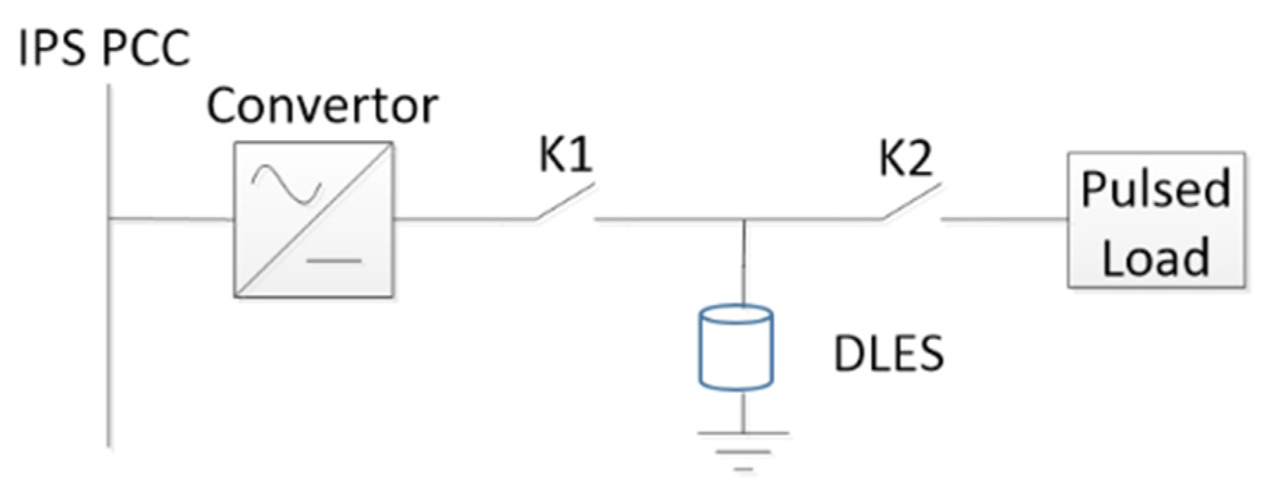
As proposed in [15,16,17,18,19], pulsed loads with high energy density are integrated into isolated power systems through an energy storage system. As proposed in [15], the single pulsed load connected to IPS with device level energy storages (DLES) is introduced in the Appendix B.
In the early stage of the optimization period, the initial ship speed is maintained as v 0 . The ship begins to accelerate at the later stage of the optimal period and the speed of the ship reaches the set value v T . The initial value of generation power p G ( t ) is the propulsion power p G ( 0 ) = k v 0 3 when the speed of the ship maintains v 0 , and during the acceleration period p G ( t ) increases to the maximum value p G , max according to the maximum uphill climbing capacity γ u . When the optimization period is about to end, p G ( t ) descends to k v T 3 according to the maximum downhill climbing capacity γ d . The ship speed will maintain v T at the end of the optimization period. The schematic diagram of the power variation of the ship’s generator during the optimization period is shown in Figure 2.
The area enclosed by the generator power curve and the horizontal axis are divided into three parts by the solid line, which correspond to the energy supplied by the ship to the pulsed load DLES, the energy used for accelerating the ship and the energy used to overcome the seawater resistance. Among them, the energy used for accelerating the ship is E = 1 2 m 1 ( v T 2 v 0 2 ) , while the energy used to overcome the seawater resistance is difficult to calculate. For calculating the third part of the energy, an approximate method is used [3]. According to [3], the power to overcome the resistance is proportional to the cube of the velocity, which is proportional to two thirds of the energy of the acceleration. The different time points in Figure 2 are calculated as
t 1 = p G , max p G ( 0 ) γ u
t 4 = T p G , max p G ( T ) γ d
t 3 = T E p G , max p G ( T )
t 2 = T E p G , max p G ( T ) p G , max p G ( T ) γ d

2.2. The Typical Operation Model and Senarios of IPS

As shown in Table 1, The typical operation modes of IPS include normal mode, emergency mode and suppression mode, where each mode includes different operation conditions. Therefore, different optimization objectives should be set for different operation modes and conditions in engineering practice. According to the working conditions and possible situations of the ship, the application scenarios of IPS in different operation modes are shown in Table 1.
A.
Normal Mode
The normal mode refers to the navigation and berthing of ships, and the application scenarios include maritime patrol, maritime operations and transportation of materials, etc. The optimization goal is mainly economy.
B.
Emergency Mode
In the emergency mode, the ship needs to face emergencies. At this time, economy is no longer the most important optimization goal, but mobility plays a more important role, and the suppression ability and self-healing also need to be considered. The optimization means are mainly to select the working point of the generator set and formulate the charging and discharging strategy of the energy storage equipment.
C.
Suppression Mode
In the suppression mode, the normal operation of the power system is ensured first, and then the suppression capability is taken as the main optimization objective, with mobility and self-healing considered at the same time.

2.3. The Chosen of Optimal Targets

It is not difficult to find that as IPS operate and work in different modes and conditions, the optimization objectives concerned in engineering practice also change.
Economy: when IPS is in normal mode, it mainly focuses on the economy of IPS, including fuel consumption, unit startup and shutdown times, etc.
Maneuverability: when IPS is in emergency mode and suppression mode, the mobility of the IPS becomes the main target of concern, including the ship speed in terminal state, the ability of emergency start and stop and steering ability, etc.
Suppressive ability: when the IPS is in emergency mode and suppression mode, suppression capability becomes a crucial research objective of IPS, which refers to the total efficiency value of multiple pulsed loads in IPS.
This paper mainly studies the most representative targets of the terminal state ship speed and the total efficiency value of multiple pulsed loads under emergency mode and suppression mode.

2.4. Mathematical Model

The optimal targets maximize both the IPS suppression capability and the ship’s final state ship speed during the optimization period. The two objectives are processed in a weighted manner, as shown in Equation (5)
max ω i , c i u , c i s , c i d , v T   ( i = 1 m V i T ω i c i + D i + β v T )
where β whose unit is s/m refers to the weight of ship speed. Through leading in β , the ship speed can be converted into a dimensionless variable which can be summed up to the same dimensionless suppression ability. i = 1 m V i T ω i c i + D i indicates the suppression ability of the ship. V i 0 is a constant utility value gained for an action of pulsed load.
The optimizable part is the acceleration process of the IPS and the charging process of the multiple pulsed loads DLES. The parameters of the multiple pulsed load DLES charging process are ω i , c i u , c i s , c i d and ship’s final state ship speed is v T .
Known parameters and constraints include initial ship speed v 0 , the lower limit of ship’s final state ship speed v T min ( v T v T min ), the optimal time period T , multiple pulsed load DLES parameters V , D , S , the lower limit of multiple pulsed load efficiency value f m ( i = 1 m V i T ω i c i + D i f m ), the maximum power of the system level energy storage (SLES) P S L E S , the ship’s weight m 1 , the propulsion power function at constant speed p M ( v ) = k v 3 , the maximum climbing rate of the generator γ u , γ d (upper and lower) and the maximum power of the generator p G , max .

3. Solution Method

3.1. Algorithm for General Situation

As proposed in [20,21], a proper problem formulation is provided. Furthermore, Ref. [22] provides a proper flowchart to reference.
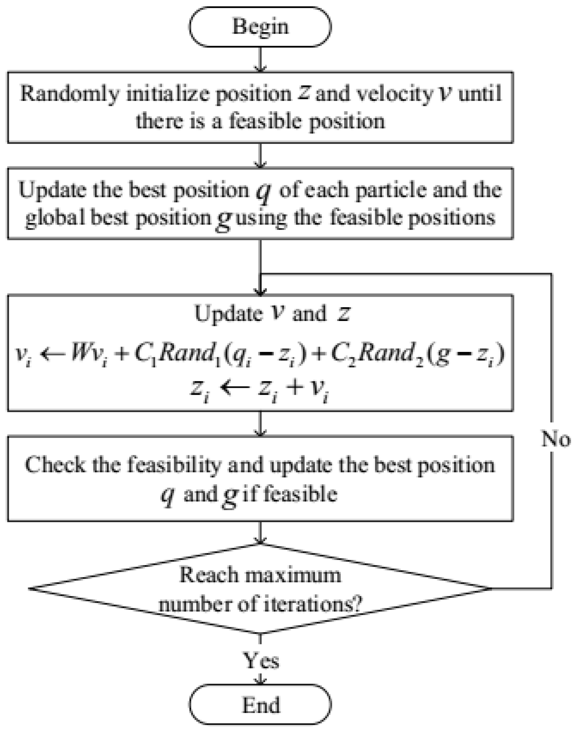
The ship’s suppression capacity and the final state ship speed are converted into single targets by weighting, that is, the objective function is converted to the Equation (5), and the solution method still adopts the PSO, which is shown in Figure 3, mentioned in [15]. As shown in [23], the details and pros and cons of the PSO method are given. Furthermore, [24,25] show that energy scheduling must consider power quality and power flow constraints.
In order to deal with complex constraints, this paper proposes adding a “feasible solution retention strategy” on the basis of the PSO algorithm, after learning from the literature [20,21,22,23,24,25]. The specific meaning is as follows: when initializing each point, check whether the newly generated solution meets the constraint after random initialization. If not, re-initialize randomly until the constraint is met. When updating the position of the point in the iteration, if the new solution calculated does not meet the constraint, it will be discarded; only the feasible solution satisfying the constraint is retained to participate in the subsequent iteration process.
The detailed technological process of the control block diagram is expressed in Appendix A.

3.2. Particular Solution Considering Typical Engineering Scenarios

Section 3.1 gives a general solution for IPS multi-objective optimization with multiple pulsed loads. There are two typical ship operation scenarios in practical engineering, namely accelerating the catch-up situation and accelerating the evacuation situation. For the above two typical scenarios, the general solution method of multi-objective optimization proposed in Section 3.1 can still be used. However, the general solution method has the problem that the optimization target weight is not easily selected. In order to solve the above problem and to better fit engineering practice, the special treatment methods of these two typical situations will be elaborated below.

3.2.1. Accelerating the Catch-Up Situation

Suppose that a ship needs to catch up and attack a target. It is hoped that the suppression capacity will be maximized during the optimization period, and in order to prevent the target from being lost, the speed of the ship at the end of the optimization period is required to be not lower than the set value.
In this case, the optimization target can be converted into Formula (6).
max ω i , c i u , c i s , c i d , v T   ( i = 1 m V i T ω i c i + D i )
In addition to the constraints given in Section 2.2, it is necessary to increase the condition that the final state ship speed is not lower than the set value.

3.2.2. Accelerating the Evacuation Situation

Assuming that the ship is in a state of being chased, it is necessary to speed up evacuation. It is desirable to maximize the speed of the ship at the end of the optimization period while ensuring that the ship has sufficient resilience to defend itself.
In this case, the optimization target can be transformed from (5) to (7).
max ω i , c i u , c i s , c i d , v T   ( v T )
In addition to the constraints given in Section 2.2, it is necessary to increase the conditions under which the suppression capability is not lower than the set value.

4. Case Study

4.1. Case Settings

The number of particle swarm samples is set to 1000, and the maximum number of iterations is set to 5000. The parameters of multiple pulsed loads and the remaining parameters of the system are shown in Table 2, Table 3 and Table 4. Columns 1 and 5 in Table 2 indicate the number of the pulsed loads.

4.2. Results and Analyses

4.2.1. General Situation

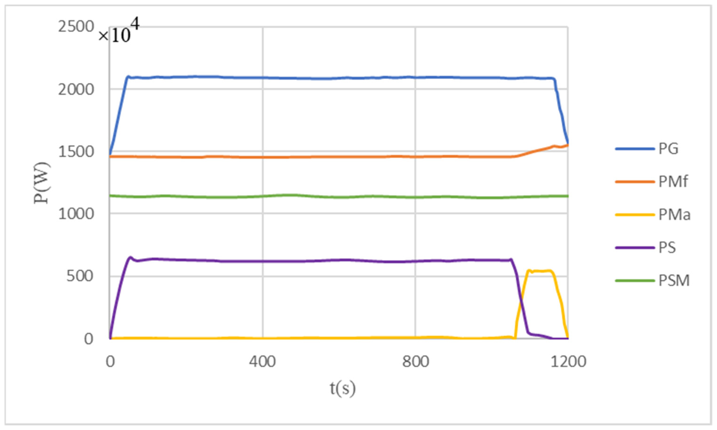
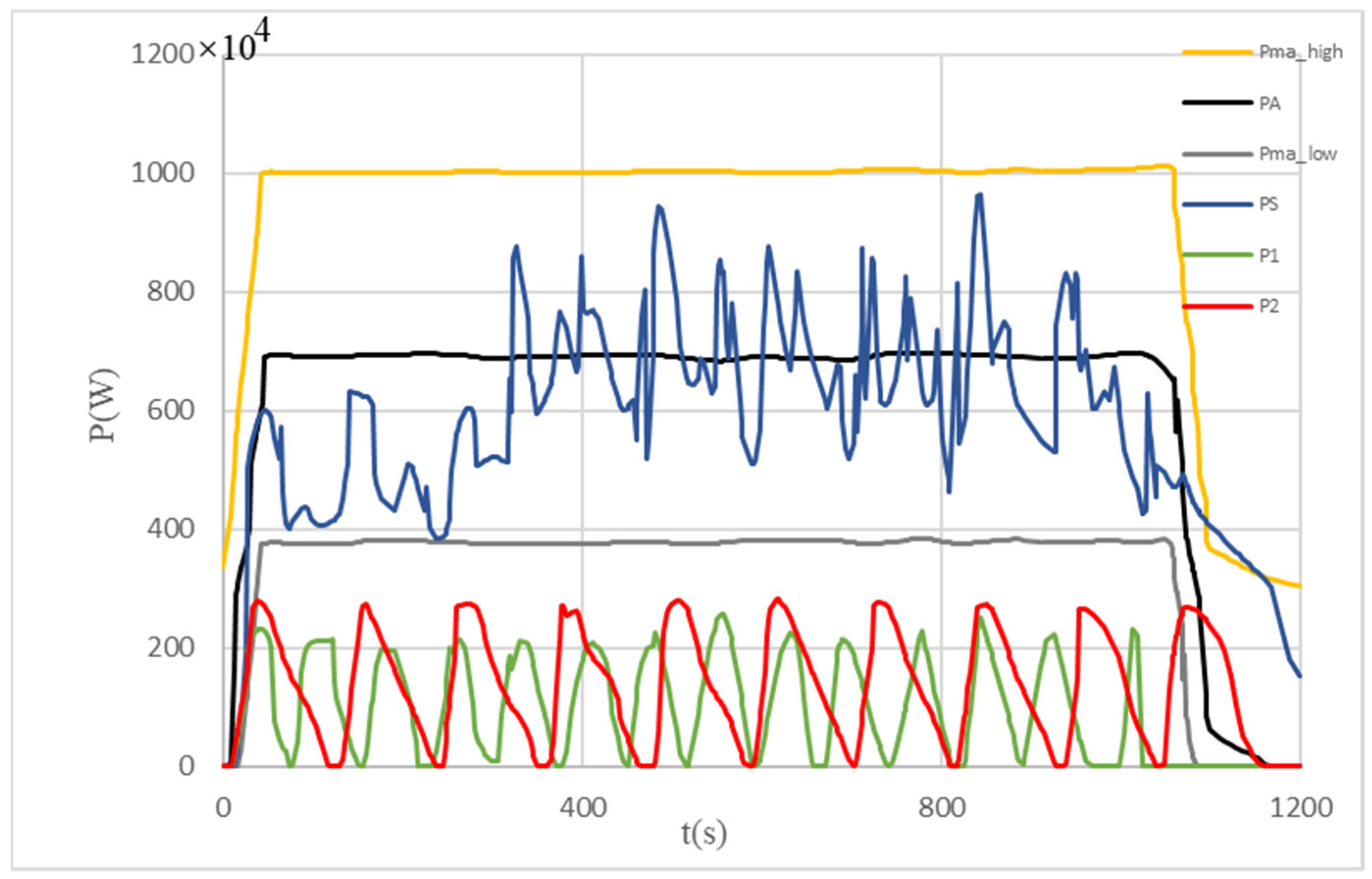
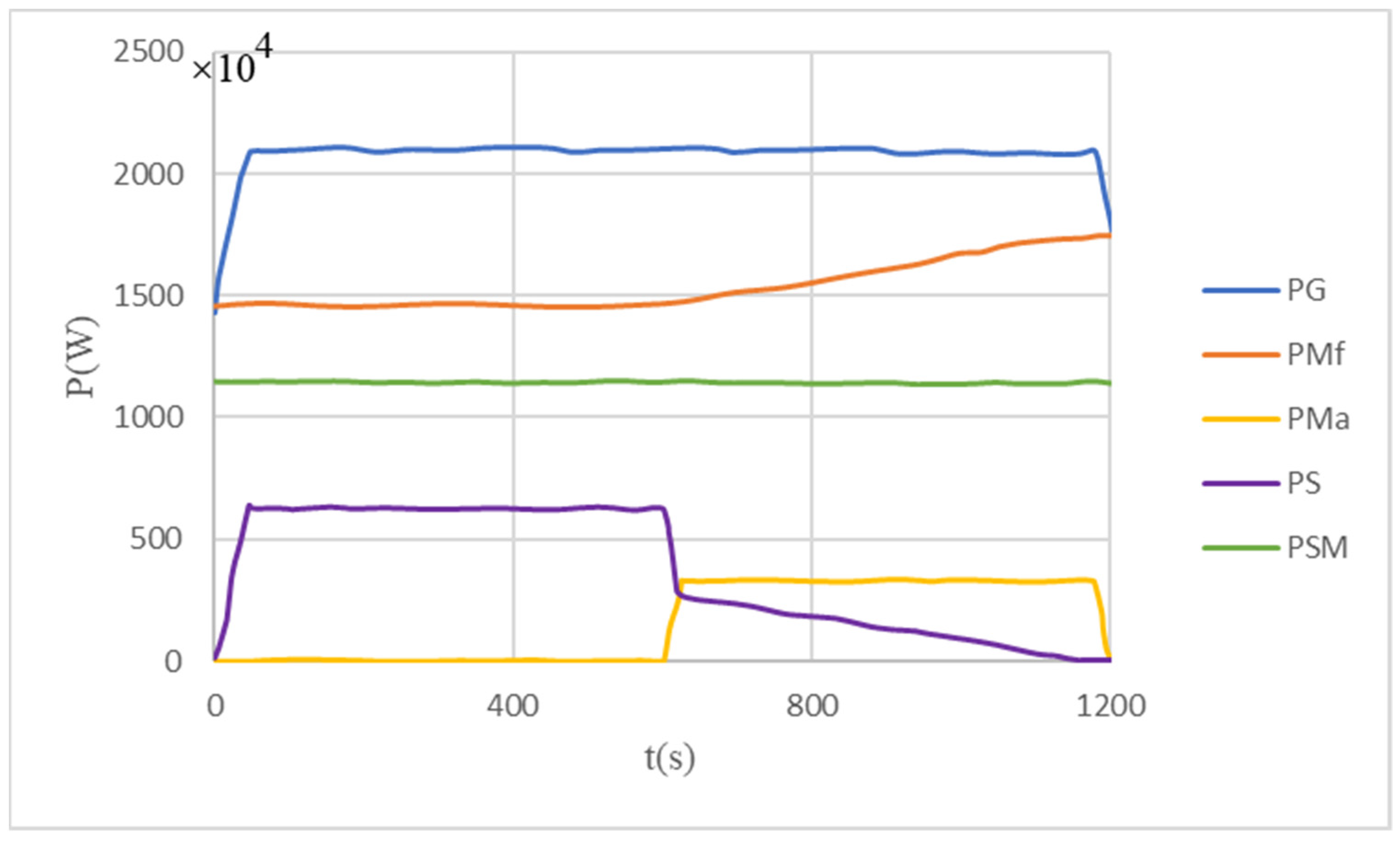
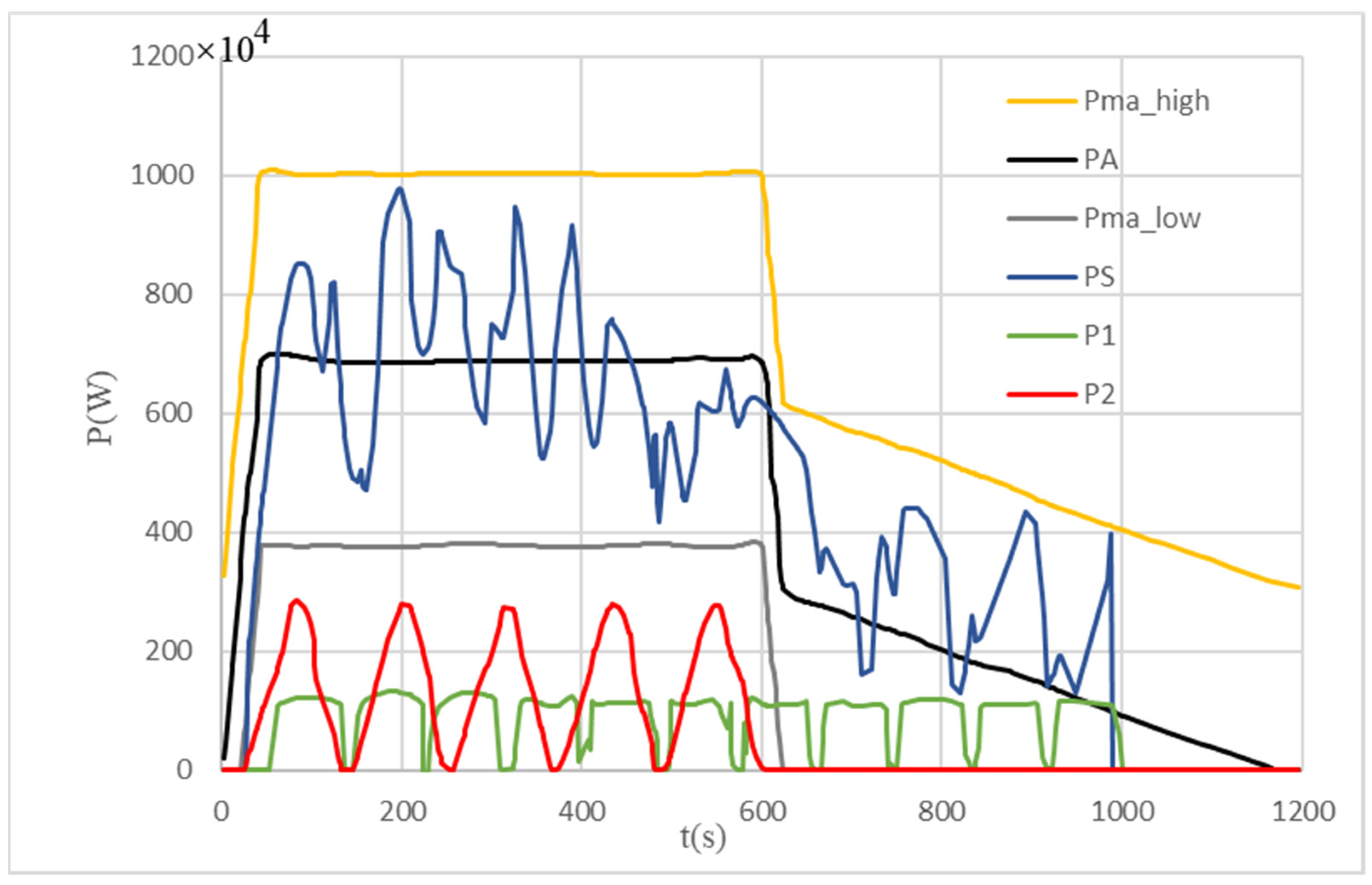
The results are shown in Figure 4 and Figure 5.
The blue curve in Figure 4 represents the generator power curve, the red curve represents the power curve of the ship used to overcome the seawater resistance, the yellow part represents the power curve of the ship for its own acceleration, and the purple part represents the available power curve of the multiple pulsed loads. The green part characterizes the power curve in which the critical value of the stability constraint is converted into a constant power load.
Considering that it is difficult to distinguish all the eight pulsed load DLES charging power curves at the same time, and people pay more attention to the results of multiple pulsed loads DLES charging power superposition, Figure 5 only gives the charging curves of two pulsed load DLES. It is represented by the red curve and the green curve, and the dark blue curve is used to represent the results of the multiple pulsed load DLES charging power superposition. The part between the upper and lower yellow lines in Figure 5 is the multiple pulsed load DLES charging power after considering the system-level energy storage. The range of fluctuations of multiple pulsed load DLES charging power superposition is always within acceptable limits. This shows that after considering the maneuvrability and the suppression capacity, the multiple pulsed load DLES always runs within the constraint range.

4.2.2. Typical Engineering Scenarios

Accelerating the Catch-Up Situation

The multiple pulsed load parameters are the same as in Section 4.1, and other parameters are shown in Table 5 and Table 6.
When it comes to dealing with the PSO algorithm, the number of particle swarm samples is set to 1000, and the maximum number of iterations is set to 3000.
The results are shown in Figure 6 and Figure 7.
The blue curve in Figure 6 represents the generator power curve, the red curve represents the power curve of the ship used to overcome the seawater resistance, the yellow part represents the power curve of the ship for its own acceleration, and the purple part represents the available power curve of the multiple pulsed loads. The green part characterizes the power curve in which the critical value of the stability constraint is converted into a constant power load.
Considering that it is difficult to distinguish all the eight pulsed load DLES charging power curves at the same time, and we pay more attention to the multiple pulsed load DLES charging power superposition results, Figure 7 only gives the charging curves of two pulsed load DLES. It is represented by the red curve and the green curve, while the dark blue curve is used to represent the result of the multiple pulsed load DLES charging power superposition. The part between the upper and lower yellow lines in Figure 7 is the multiple pulsed load DLES charging power after considering the system-level energy storage. The range of fluctuations of the multiple pulsed load DLES charging power superimposed on the ship during acceleration is always within acceptable limits.

Accelerating the Evacuation Situation

The multiple pulsed loads parameters are the same as in Section 4.1. Other parameters are shown in Table 7 and Table 8.
When using the PSO algorithm, the number of particle swarm samples is set to 1000, and the maximum number of iterations is set to 3000.
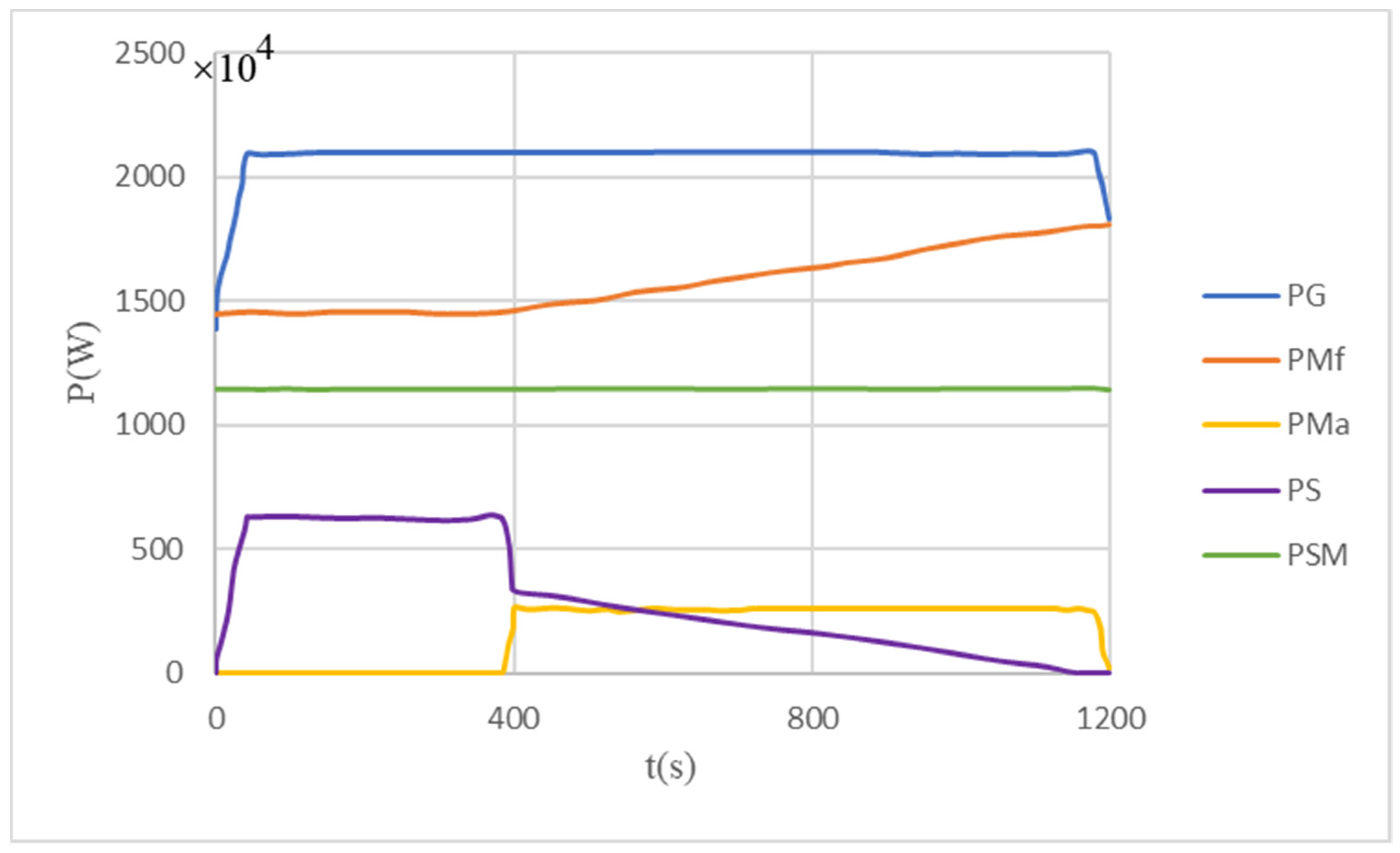
Figure 8 and Figure 9 show the optimization results of accelerating the evacuation situation. At this time, mobility is considered to be a constraint. The meaning of the curve in the figure is similar to the curves in Figure 6 and Figure 7. The result of multiple pulsed load DLES charging power superposition at accelerated evacuation is always within acceptable limits. This shows that the multiple pulsed load DLES always runs within the constraint range while ensuring that the ship has sufficient resilience and maximizes the speed of the ship at the end of the optimized time period.

5. Conclusions and Prospects

IPS is often in the following three modes when performing tasks: normal mode, emergency mode and suppression mode. Each mode contains different operation scenarios. Under these different scenarios, the optimization operation objectives of IPS will change among economy, mobility, self-healing and suppression capabilities. The corresponding optimization problem can be single objective or multi-objective.
In this paper, the IPS multi-operation mode is analyzed, and the multi-objective optimal scheduling model is designed with two optimization objectives: the optimal mobility and the maximum multiple pulsed load performance value. By introducing the concept of ship speed at the end state, the IPS maneuvrability is properly characterized by the final state ship speed, combined with the maximum efficiency of multiple pulsed loads, and a multi-objective optimization model of weighted form is constructed with a general given solution method.
Aiming at the two typical scenarios of accelerating the catch-up situation and accelerating the evacuation situation in practical engineering, the method of transforming the optimization target into the constraint condition is adopted. The multi-objective optimization problem is transformed into the single-objective optimization problem and the effectiveness of the proposed method is verified by simulation. Furthermore, the multi-objective optimization algorithm proposed in this work can also be used for reference in studying the renewable energy carrying capacity of receiving-end power grid regarding the multi-spatial-temporal distribution characteristics of renewable energy.
As described in [26,27], the definition of the optimal strategy for battery utilization is considered. The proposed multi-objective method can take it into account just by adding another optimal target. However, the proposed method was still unable to deal with multiple time varying pulsed loads. This will still be the main research direction of the authors in the future.

Author Contributions

Conceptualization, F.L. and B.Q.; methodology, F.L. and B.Q.; software, F.L. and B.Q.; validation, F.L. and B.Q.; formal analysis, F.L., B.Q., D.L. and K.S.; investigation, F.L. and B.Q.; resources, F.L. and B.Q.; data curation, F.L., B.Q. and D.W.; writing—original draft preparation, F.L. and B.Q.; writing—review and editing, F.L., B.Q., H.L., C.Z. and T.T. All authors have read and agreed to the published version of the manuscript.

Funding

This research received the funding by Science and Technology Project of State Grid Corporation of China (a study of the renewable energy carrying capacity of receiving-end power grid considering the multi spatial-temporal distribution characteristics of renewable energy, 5100-202256018A-1-1-ZN).

Institutional Review Board Statement

Not applicable.

Informed Consent Statement

Not applicable.

Data Availability Statement

Not applicable.

Acknowledgments

This work is supported by Science and Technology Project of State Grid Corporation of China (a study of the renewable energy carrying capacity of receiving-end power grid considering the multi spatial-temporal distribution characteristics of renewable energy, 5100-202256018A-1-1-ZN).

Conflicts of Interest

The authors declare no conflict of interest.

Appendix A

Due to the fast convergence and high precision of the PSO algorithm, which is suitable for dealing with complex constraints, this paper uses an algorithm based on PSO to solve the proposed optimization model [16]. The algorithm involves the following five steps.
Step 1:
Randomly initialize a group of controllable variable values and the variation of controllable variables, and record them as { z } and { υ } . In the PSO algorithm, the value of the controllable variable is called position, and the change of the controllable variable is called velocity. Each z composed of controllable time points of DLES charging power curve of all pulse loads, which can be denoted by z = { ω i , c i u , c i s , c i d } . Each υ consists of the controllable time point variation of DLES charging power curve of all pulsed loads, which can be denoted by v = { Δ ω i , Δ c i u , Δ c i s , Δ c i d } .
Step 2:
Check whether the constraint is satisfied. If the constraint is not satisfied, repeat step 1 to perform initialization again. Otherwise, all feasible solutions are marked as candidate solutions and represented as { q } .
Step 3:
Each candidate solution is updated with randomly selected υ . If the maximum number of searches is reached, perform step 5.
Step 4:
Check whether the newly generated solution meets all constraints, and release the constraint satisfied solution into the candidate solution set, then return to step 3.
Step 5:
Select the optimal solution from the candidate solution set.

Appendix B

Suppose that each pulsed load is connected to a PCC bus with a DLES. As shown in Figure A1, the DLES is charged when K1 is closed and K2 is open. Then, when K1 is open and K2 is closed, the pulsed load is powered by the DLES to fulfill its function. Generally, it takes much more time to charge the DLES than discharge it to supply the pulsed load. Consequently, the IPS may experience relatively small load variations instead of energizing the pulsed load directly.
Figure A1. Single pulsed load connected to IPS with a DLES.
Sustainability 14 16021 g0a1

References

  1. Dashkovskiy, S.N.; Rüffer, B.S. Local ISS of large-scale interconnections and estimates for stability regions. Syst. Control. Lett. 2010, 59, 241–247. [Google Scholar] [CrossRef]
  2. Ibrahim, M.; Jemei, S.; Wimmer, G.; Hissel, D. Nonlinear autoregressive neural network in an energy management strategy for battery/ultra-capacitor hybrid electrical vehicles. Electr. Power Syst. Res. 2016, 136, 262–269. [Google Scholar] [CrossRef]
  3. Qin, B.; Wang, W.; Li, W.; Li, F.; Ding, T. Multiobjective Energy Management of Multiple Pulsed Loads in Shipboard Integrated Power Systems. IEEE Syst. J. 2022, 1–12, (Early Access Article). [Google Scholar] [CrossRef]
  4. Tan, L.; Yang, Q.; Im, W.; Liu, W. Adaptive critic design based cooperative control for pulsed power loads accommodation in shipboard power system. IET Gener. Transm. Distrib. 2016, 10, 2739–2747. [Google Scholar] [CrossRef] [Green Version]
  5. Im, W.S.; Wang, C.; Tan, L.; Liu, W.; Liu, L. Cooperative controls for pulsed power load accommodation in a shipboard power system. IEEE Trans. Power Syst. 2016, 31, 5180–5189. [Google Scholar] [CrossRef]
  6. Qin, B.; Liu, W.; Li, H.; Ding, T.; Ma, K.; Liu, T. Impact of System Inherent Characteristics on Initial-Stage Short-Circuit Current of MMC-based MTDC Transmission systems. IEEE Trans. Power Syst. 2022, 37, 3913–3922. [Google Scholar] [CrossRef]
  7. Mohamed, A.; Salehi, V.; Mohammed, O. Real-time energy management algorithm for mitigation of pulse loads in hybrid IPSs. IEEE Trans. Smart Grid 2012, 3, 1911–1922. [Google Scholar] [CrossRef]
  8. Vafamand, N.; Mardani, M.M.; Khooban, M.H.; Blaabjerg, F.; Boudjadar, J. Pulsed power load effect mitigation in DC shipboard microgrids: A constrained model-predictive approach. IET Power Electron. 2019, 12, 2155–2160. [Google Scholar] [CrossRef]
  9. Penthia, T.; Panda, A.K.; Patnaik, N.; Mohanty, P.R. Performance of SMES system with non-linear dynamic evolution control approach for pulsed power load compensation. IET Gener. Transmiss. Distrib. 2020, 14, 1872–1881. [Google Scholar] [CrossRef]
  10. Weiming, M.A. On comprehensive development of electrization and informationization in naval ships. J. Nav. Univ. Eng. 2010, 22, 1–4. [Google Scholar]
  11. Hein, K.; Xu, Y.; Wilson, G.; Gupta, A.K. Coordinated optimal voyage planning and energy management of all-electric ship with hybrid energy storage system. IEEE Trans. Power Syst 2021, 36, 2355–2365. [Google Scholar] [CrossRef]
  12. Li, H.; Qin, B.; Jiang, Y.; Zhao, Y.; Shi, W. Data-Driven Optimal Scheduling for Underground Space Based Integrated Hydrogen Energy System. IET Renew. Power Gener. 2022, 16, 2521–2531. [Google Scholar] [CrossRef]
  13. Feng, X.; Butler-Purry, K.L.; Zourntos, T. A multi-agent system framework for real-time electric load management in MVAC all-electric ship power systems. IEEE Trans. Power Syst. 2015, 30, 1327–1336. [Google Scholar] [CrossRef]
  14. Elsayed, A.T.; Mohammed, O.A. Distributed flywheel energy storage systems for mitigating the effects of pulsed loads. In Proceedings of the 2014 IEEE PES General Meeting Conference & Exposition, National Harbor, MD, USA, 27–31 July 2014; pp. 1–5. [Google Scholar]
  15. Li, F.; Chen, Y.; Xie, R.; Shen, C.; Zhang, L.; Qin, B. Optimal Operation Planning for Orchestrating Multiple pulsed loads with Transient Stability Constraints in Isolated Power Systems. IEEE Access 2018, 6, 18685–18693. [Google Scholar] [CrossRef]
  16. Salehi, V.; Mirafzal, B.; Mohammed, O. Pulse-load effects on ship power system stability. In Proceedings of the IECON 2010-36th Annual Conference on IEEE Industrial Electronics Society, Glendale, CA, USA, 7–10 November 2010; pp. 3353–3358. [Google Scholar]
  17. Lashway, C.R.; Elsayed, A.T.; Mohammed, O.A. Hybrid energy storage management in ship power systems with multiple pulsed loads. Electr. Power Syst. Res. 2016, 141, 50–62. [Google Scholar] [CrossRef] [Green Version]
  18. Wang, Y.; Wu, Q.; Gong, W.; Gryning, M.S. H∞ robust current control for DFIG-Based wind turbine subject to grid voltage dis-tortions. IEEE Trans. Sustain. Energy 2017, 8, 816–825. [Google Scholar] [CrossRef] [Green Version]
  19. Qin, B.; Sun, H.; Ma, J.; Li, W.; Ding, T.; Wang, Z.; Zomaya, A. Robust H∞ control of doubly fed wind generator via state-dependent riccati equation technique. IEEE Trans. Power Syst. 2019, 34, 2390–2400. [Google Scholar] [CrossRef]
  20. Shahzad, M.; Akram, W.; Arif, M.; Khan, U.; Ullah, B. Optimal siting and sizing of distributed generators by strawberry plant propagation algorithm. Energies 2021, 14, 1744. [Google Scholar] [CrossRef]
  21. Shahzad, M.; Shafiullah, Q.; Akram, W.; Arif, M.; Ullah, B. Reactive power support in radial distribution network using mine blast algorithm. Elektron. Ir Elektrotechnika 2021, 27, 33–40. [Google Scholar] [CrossRef]
  22. Shahzad, M.; Qadir, A.; Ullah, N.; Mahmood, Z.; Saad, N.M.; Ali, S.S.A. Optimization of On-Grid Hybrid Renewable Energy System: A Case Study on Azad Jammu and Kashmir. Sustainability 2022, 14, 5757. [Google Scholar] [CrossRef]
  23. Bilal, M.; Shahzad, M.; Arif, M.; Ullah, B.; Hisham, S.B.; Ali, S.S.A. Annual Cost and Loss Minimization in a Radial Distribution Network by Capacitor Allocation Using PSO. Appl. Sci. 2021, 11, 11840. [Google Scholar] [CrossRef]
  24. Scarabaggio, P.; Carli, R.; Dotoli, M. Noncooperative Equilibrium Seeking in Distributed Energy Systems Under AC Power Flow Nonlinear Constraints. IEEE Trans. Control. Netw. Syst. 2022, 1–12. [Google Scholar] [CrossRef]
  25. Yao, M.; Molzahn, D.K.; Mathieu, J.L. An optimal power-flow approach to improve power system voltage stability using demand response, IEEE Trans. Control. Netw. Syst. 2019, 6, 1015–1025. [Google Scholar] [CrossRef]
  26. Scarabaggio, P.; Carli, R.; Cavone, G.; Dotoli, M. Smart Control Strategies for Primary Frequency Regulation through Electric Vehicles: A Battery Degradation Perspective. Energies 2020, 13, 4586. [Google Scholar] [CrossRef]
  27. Yan, G.; Liu, D.; Li, J. A cost accounting method of the Li-ion battery energy storage system for frequency regulation considering the effect of life degradation. Prot. Control. Mod. Power Syst. 2018, 3, 4. [Google Scholar] [CrossRef]
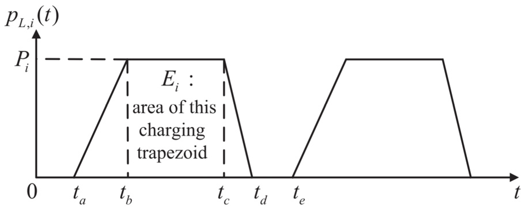
Figure 1. Charging power curve of supercapacitor single charge process.
Sustainability 14 16021 g001
Figure 2. The schematic diagram of the power variation of the ship’s generator.
Sustainability 14 16021 g002
Figure 3. The basic PSO control block diagram.
Sustainability 14 16021 g003
Figure 4. Constant power load curve corresponding to generator output, ship power consumption, available power and stability constraints.
Sustainability 14 16021 g004
Figure 5. Multiple pulsed loads DLES charging power and constraint curve.
Sustainability 14 16021 g005
Figure 6. Constant power load curve corresponding to generator output, ship power consumption, available power and stability constraints in the case of accelerated catch-up.
Sustainability 14 16021 g006
Figure 7. Multiple pulsed load DLES charging power and constraint curve under accelerated catch-up situation.
Sustainability 14 16021 g007
Figure 8. Constant power load curve corresponding to generator output, ship power consumption, available power and stability constraints in the case of accelerated evacuation.
Sustainability 14 16021 g008
Figure 9. Multiple pulsed load DLES charging power and constraint curve under accelerated evacuation.
Sustainability 14 16021 g009
Table 1. The typical operation scenarios of IPS.
ModeWorking
Condition
TargetVariables and Means
Normal
Mode
Berthing on shoreEconomyLong time scale: Load
forecasting,
Unit commitment
Accelerating
DeceleratingMiddle time scale: Optimization of generator operating point
Uniform
Velocity
Berthing at seaShort time scale: Automatic generation control
Emergency
Mode
Emergency transferSafety, self-healing, ManeuverabilityRegulating power distribution
ComlossSuppressive abilityCharging capacity
Suppression ModeAttackManeuverabilityCharging and discharging power regulation
DefenseSuppressive abilityPower distribution
Table 2. Parameters of pulsed loads.
No. S (MJ) D (s) V No. S (MJ) D (s) V
1805105145816
21607256130920
312010187906.58
410561381101119
Table 3. Remaining parameters of the system (1).
v 0
m/s
m 1
t
v T
m/s
k
MW/(m/s)3
T
s
P S L E S
MW
β
s/m
8500,000100.031200310
Table 4. Remaining parameters of the system (2).
λ i d
MW/s
p G , max
MW
γ u
MW/s
λ i u
MW/s
γ d
MW/s
v T min
m/s
v T max
m/s
0.4220.150.40.158.068.67
Table 5. Remaining parameters of the system (1).
v 0
m/s
m 1
T
v T
m/s
k
MW/(m/s)3
T
S
P S L E S
MW
8500,000100.0312003
Table 6. Remaining parameters of the system (2).
λ i d
MW/s
p G , max
MW
γ u
MW/s
λ i u
MW/s
γ d
MW/s
0.4220.150.40.15
Table 7. Remaining parameters of the system (1).
v 0
m/s
m 1
t
f m k
MW/(m/s)3
T
s
P S L E S
MW
8500,00018000.0312003
Table 8. Remaining parameters of the system (2).
λ i d
MW/s
p G , max
MW
γ u
MW/s
λ i u
MW/s
γ d
MW/s
0.4220.150.40.15
Publisher’s Note: MDPI stays neutral with regard to jurisdictional claims in published maps and institutional affiliations.