Article

Mechanics Modeling and Simulation Analysis of a Novel Articulated Chassis for Forestry

1
College of Transportation and Civil Engineering, Fujian Agriculture and Forestry University, Fuzhou 350002, China
2
Forestry Department of Gutian County, Gutian, Ningde 352200, China
*
Author to whom correspondence should be addressed.
Sustainability 2022, 14(23), 16118; https://doi.org/10.3390/su142316118
Submission received: 15 October 2022 / Revised: 22 November 2022 / Accepted: 24 November 2022 / Published: 2 December 2022
(This article belongs to the Section Sustainable Engineering and Science)

Abstract

:
When the power chassis of general forest machinery is working on uneven terrains, the power is insufficient due to the poor traction between the wheels and the road surface, which affects the driving operation of the entire vehicle. According to the principle of multiple-degree-of-freedom profiling, a novel articulated chassis for forestry was designed. The innovative articulated structure realizes active pitching, active deflection, and passive torsion in the front and rear frames. The kinematics and dynamics (mechanics modeling) of the articulated structure were analyzed, and a theoretical model of the relationship between the rotation angle of the rotary shaft and the pitching angle of the front and rear frames was established. A three-dimensional model of the forestry chassis was established using SolidWorks, and a kinematic simulation of the articulated structure was performed by ADAMS. When the simulation and theoretical results were compared, the maximum error was found to occur at the position where the rotation angle of the rotary shaft was 90° and was less than 1%, demonstrating the accuracy of the theoretical model. Furthermore, a chassis working condition simulation experiment was conducted using ADAMS. When climbing a slope with a wheel speed of 1.39 rev/s, the duration of the effective driving force of the front wheels of the novel chassis was 61.5% longer than the ordinary chassis. In steep-convex-obstacle climbing, the active pitch function of the novel chassis can ensure that the wheels have a good contact with the road, and the load can pass through an obstacle smoothly. For single-side obstacle crossing, the wheels of the novel chassis can provide a continuous and stable effective driving force for obstacle crossing owing to the excellent road surface profiling.

1. Introduction

The agriculture and forestry industry in the hilly and mountainous regions of South China is relatively undeveloped. Affected by the terrain, the plowland and forest land are scattered, and the block area is small; furthermore, the inclines between blocks are clear. It is difficult for mechanized agricultural and forestry equipment to enter the operation environment since no suitable power chassis exists. Therefore, a mechanical power chassis with terrain adaptability is required [1,2,3,4,5]. To mechanize the agriculture and forestry industry, it is necessary for power chassis to enter forest areas and operate. However, at present, most power chassis of forestry machinery in hilly and mountainous regions are ordinary tractor chassis. Few studies have explored special forest chassis suitable for profiling walking in hilly and mountainous regions. It is particularly important to develop special forest chassis that can be driven and operated in rugged terrain [6,7,8,9,10,11,12].
Research on special equipment chassis has mainly concentrated on space exploration, seabed mining, and other fields [13,14], while there has been less research on forestry vehicle operation [15,16]. Smith T et al. developed ATHLETE rover, whose full name was All-Terrain Hex-Limbed Extra-Terrestrial Explorer. Athlete Rover was a robot with six swinging arms and wheel legs, and each swinging arm wheel was a three-joint series structure [17]. It was modeled on the human body to set the hip joint, knee joint, and ankle joint, and had strong self-adjustment ability and road passing ability; however, due to the complexity of robot structure and control system, it was difficult to apply in practice. Zhao et al. designed an articulated crawler-type seabed mining vehicle that is suitable for complex and harsh seamount environments, established a virtual prototype using simulation software, and performed an obstacle surmounting simulation analysis under two typical working conditions. The results proved the accuracy of the model and provided theoretical reference for the development of a physical prototype [18]. The swing frame structure has favorable road profiling and can automatically adjust the wheel position according to the terrain conditions, ensuring good traction with the road surface. Edlund et al. designed a long-tracked bogie structure. This design took into account the advantages of swing frame and track structure [19]. The swing frame had good pavement profiling to ensure a good contact between the wheels and pavement. Tracks were installed on the outside of the wheels to help improve the traction of the chassis and facilitate crossing obstacles. The swing frame track structure with large middle wheels and small wheels on both sides could protect the road surface. Liu et al. designed a dynamic leveling chassis for agricultural profiling walking in uneven areas to address the poor trafficability of agricultural machinery and difficulty in maintaining the level of the vehicle body [6,20,21,22]. The chassis had a four-group swing frame structure, and the angle of the swing frame could be accurately adjusted through vehicle body leveling control, solving the problems of agricultural power chassis walking, and operating in uneven areas. However, when the traditional “V”-type or “man”-type swing frame turns, the wheels on both sides of the swing frame end are subject to lateral friction with the road surface, and there is no instantaneous center of rotation. The tire is subject to severe lateral friction and wear, and the steering mechanism is also vulnerable to impact and damage [23,24,25,26,27]. Zhu et al. designed a three-degree-of-freedom articulated chassis that was capable of three-way adjustment of the front and rear frames of the chassis. Good road profiling improved the vehicle driving performance on uneven roads [28,29,30,31,32]. However, the pitch function of the three-degree-of-freedom articulated structure in this design involved passive adjustment. The chassis required six or eight wheels due to the self-weights of the front and rear frames. The increase in wheel number led to an increase in chassis length and decrease in flexibility. In addition, the rear frame wheels had no instantaneous center of rotation when turning, and the lateral friction was high.
In this study, a novel articulated chassis for forestry was designed based on a multiple-degree-of-freedom profiling principle. On the contrary to the traditional articulated structure, the pitch function of the front and rear frames in this design is controlled by a servo motor, enabling the chassis to climb and surmount obstacles actively. In addition, the need for the traditional three-degree-of-freedom articulated structure to use six or eight wheels due to the self-weight of the front and rear frames is eliminated. The novel articulated chassis is equipped with four wheels, and the contact point between the wheel and the road surface is the instantaneous center of rotation when turning, with small lateral friction and flexible operation. The kinematics and dynamics (mechanics modeling) of the novel articulated structure were analyzed, and a theoretical model of the relationship between the rotation angle of the rotary shaft and pitch angle of the front and rear frames was established. The quantitative relationship between the output torque of the servo motor and the angular acceleration and angle of the end pitch plate was determined, and the theoretical limit pitch angle of the chassis over the slope was obtained. A simulation analysis of the pitch operation of the novel articulated structure was performed with ADAMS to verify the accuracy of the model. In addition, the complex terrain environment in the forest area was simplified into three working conditions: Climbing slope, steep convex obstacle, and single-sided obstacle. Three working conditions were established in ADAMS, and simulation experiments were performed. Compared with an ordinary chassis, the novel articulated chassis for forestry had better pavement profiling and dynamic performance.

2. Materials and Methods

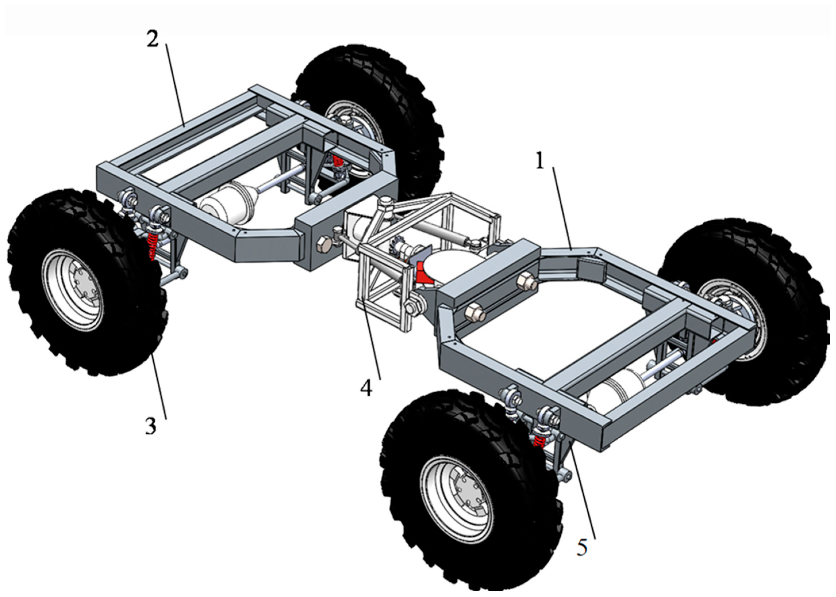
2.1. Chassis Structure

The world has a high forest coverage rate, and there are various and complex tree species. The complex terrain environment in the forest area requires a power chassis with high trafficability [33,34,35]. The novel chassis developed in this study employs four-wheel full-time drive and articulated steering. Compared with an ordinary chassis, it has good pavement profiling and power performance, has flexible steering, and is suitable for driving in narrow forest areas.
The novel articulated chassis for forestry is mainly composed of a front frame, an articulated structure, a rear frame, and wheels. The front and rear frames of the chassis are connected through an articulated structure, and the four wheels are connected to the front and rear frames through independent suspension. The power output by the engine is transmitted to the transfer case through the clutch and divided into two channels. It is transmitted to the corresponding interaxle differential through the transmission shaft and then transmitted to each wheel through the half shaft to realize the four-wheel full-time drive and provide sufficient power for the chassis to operate in the forest, as shown in Figure 1 [36,37,38].

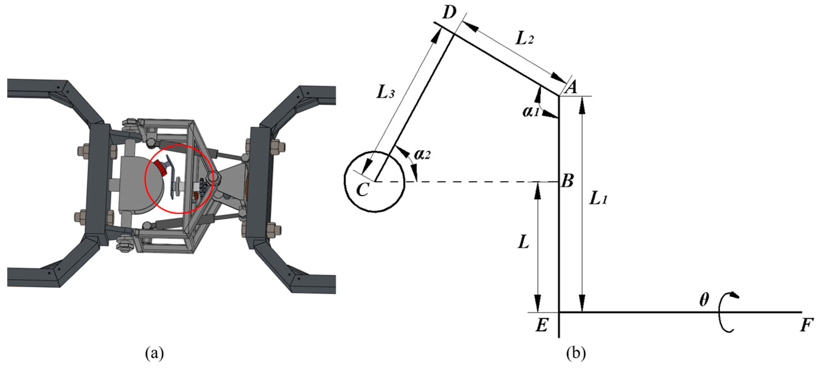
2.2. Three-Degree-of-Freedom Articulated Structure with Active Pitching Function

The three-degree-of-freedom articulated structure is the most important component of the novel forest articulated chassis. It makes the pitching, deflection, and torsion movement of the front and rear frames possible. The pitching and deflection are active control, and the torsion is passive adjustment. The articulated structure is mainly composed of hydraulic components, pitching connectors, and torsion connectors, as shown in Figure 2a. When the chassis turns, the hydraulic components drive the steering hydraulic cylinder 5 (or 8) to contract (extend) and drive the steering hydraulic cylinder 8 (or 5) to extend (contract); then, the front and rear frames deflect to realize chassis steering. When the chassis climbs over a slope or an obstacle, the servo motor drives gear 9 to rotate, driving rotary shaft 4 to rotate in a full circle in a plane perpendicular to the driving direction. Ball joint pair 11 at the end of rotary shaft 4 is connected to pitching plate 2 through slider 12, and the full circle rotation of rotary shaft 4 is converted into the reciprocating swing of pitching plate 2 to make the active pitching of the front and rear frames of the chassis possible, as shown in Figure 2b–e. When the chassis surmounts an obstacle on one side, torsion connector 6 drives the articulated structure and front frame 1 to passively twist around rear frame 7, making it possible to surmount the obstacle on one side. The novel articulated structure can control the front and rear frames to follow the uneven road, ensure full-time contact between the wheels and the road, and solve the problem of insufficient power resulting from poor traction between them.

2.3. Kinematics and Dynamics Analysis of Key Mechanism of Chassis

2.3.1. Kinematics Analysis of Articulated Structure

The servo motor drives the gear to rotate, driving the rotary shaft to rotate in the entire circle on the plane perpendicular to the driving direction. The ball joint pair at the end of the rotary shaft is connected to the pitching plate through the slider, and the entire rotation of the rotary shaft is converted into a reciprocating swing of the pitching plate to realize the active pitching of the front and rear frames of the chassis. According to the working principle of the pitching motion of the front and rear frames, the ball joint pair at the end is simplified into a circle, and the other parts are rigid connection structures, which can be simplified into line segments. The structural diagram of the rotary shaft as shown in Figure 3 is established. Rod CD in the figure is the ball joint pair arm, the circular C is the ball joint pair ball head, and rods AD, AE, and EF are the rigid parts of the rotary shaft. According to the geometric relationship of each parameter, the following can be obtained:
L = L 1 + L 2 sin ( α 1 90 ) L 3 sin α 2 = L 1 L 2 cos α 1 L 3 sin α 2
Here, L is the rotary radius of the ball head around rotary shaft EF;
L 1 is the length of rod AE;
L 2 is the length of rod AD;
L 3 is the length of rod CD, where point C is the center point of ball head;
α 1 is the angle between rods AE and AD;
α 2 is the angle between rod CD and horizontal line.
Assuming that the horizontal position of the pitching plate is the initial position, the center of the pitching plate semicircle is the coordinate origin O, the swing axis direction of the pitching plate is the x-axis, and the rotation axis direction of the rotary shaft is the y-axis. The z-axis is determined according to the right-hand screw rule and the spatial rectangular coordinate system, as shown in Figure 2a. In the xoz-plane, it is assumed that the rotary shaft rotates by an angle θ, point A is the initial position of the center point of the rotary shaft ball head, and point B is its end position, as shown in Figure 4.
According to the geometric relationship and cosine theorem in the figure, the x-axis coordinate difference, z-axis coordinate difference, and square value of the chord length of two points A and B can be obtained as follows:
A B 2 = 2 L 2 ( 1 cos θ )
Δ z = L sin θ
Δ x = L ( 1 cos θ )
Here, θ is the rotation angle of rotary shaft;
Δ z is the z-axis coordinate difference between points A and B;
Δ x is the x-axis coordinate difference between points A and B.
The motion of the ball head of the rotary shaft is regarded as a compound circular motion in the xoy-plane and yoz-plane. Similar to the above method, a spatial rectangular coordinate system is established, as shown in Figure 5a. Point C is the initial position of the center point of the rotary shaft ball head, point E is its end position, and point D is the junction point of the circular motion. Clearly, the rotary radii of the above two circular motions are equal, and CD ⊥ DE can be used to solve the square value of CE.
As shown in Figure 5b, the y-axis coordinate difference and the square value of two points C and D can be obtained in the yoz-plane according to the following geometric relationship:
Δ y = P ( 1 cos α )
C D 2 = 2 P 2 ( 1 cos α )
Here, P is the radius of pitching plate;
α is the pitch angle of pitching plate;
Δ y is the y-axis coordinate difference between points C and D.
The ball head of the rotary shaft has no linear displacement in the direction of the rotation axis, thus the difference between the y-axis coordinates of points D and E is equal to the corresponding difference between points C and D, as shown in Figure 5c. The square value of DE can be obtained by combining Equations (4) and (5) in the xoy-plane as follows:
D E 2 = L 2 ( 1 cos θ ) 2 + P 2 ( 1 cos α ) 2
According to the above analysis, the lengths of AB and CE are equal. Combining Equations (2), (6), and (7), one can obtain the following:
L 2 ( 1 cos θ ) 2 + P 2 ( 1 cos α ) 2 + 2 P 2 ( 1 cos α ) = 2 L 2 ( 1 cos θ )
The above formula is simplified to obtain the following:
P 2 cos 2 α 4 P 2 cos α + 3 P 2 L 2 sin 2 θ = 0
Equation (9) is a quadratic equation of one variable. According to the root formula, the solution is obtained as follows:
cos α = 4 P 2 ± 4 P 4 + 4 P 2 L 2 sin 2 θ 2 P 2
where 4 P 4 + 4 P 2 L 2 sin 2 θ 2 P 2 in the molecule. If the plus sign is taken, cos α ≥ 3 (omitted). If the minus sign is taken, cos α ≤ 1. In addition, the front and rear frames present two postures: Pitching down and pitching up. Therefore, the pitching angle is distinguished by positive and negative conditions. Finally, the relationship between the rotation angle θ of the rotary shaft and the pitch angle α of the front and rear frames is obtained as follows:
α = { arccos 4 P 2 4 P 4 + 4 P 2 L 2 sin 2 θ 2 P 2 , ( 0 ° θ < 180 ° ) arccos 4 P 2 4 P 4 + 4 P 2 L 2 sin 2 θ 2 P 2 , ( 180 ° θ 360 ° )
According to Equation (11), without considering the articulated structure parameters, the pitch angle α of the front and rear frames is only related to the rotation angle θ of the rotary shaft. The radius of pitch plate P is 140 mm, and the turning radius of rotary shaft L can be obtained by Equation (1). L 1 , L 2 , L 3 , α 1 , and α 2 are shown in Table 1.

2.3.2. Dynamics Analysis of Articulated Structure

Considering the action of the articulated structure servo motor, the motor actively exerts a rotational torque on the rotary shaft, which generates a nonconservative force to conduct work on the system [39,40,41,42]. In this study, the Lagrange equation method was used to analyze the dynamics of the articulated structure. The rotation angle θ of the rotary shaft was selected as the generalized coordinate, and the mass of the ball head was equivalent to the point mass. Similar to Figure 4, the dynamic model of the ball head of the rotary shaft is established as shown in Figure 6.
The kinetic energy K of the ball head is calculated as follows:
K = 1 2 m v 2 = 1 2 m L 2 θ ˙ 2
Here, m is the mass of the ball head;
v is the linear velocity of the ball head;
L is the rotary radius of the ball head;
θ ˙ is the rotational angular velocity of the rotary shaft.
Assuming that the initial position of the ball head is on the zero potential energy surface, the potential energy U of the ball head is calculated as follows:
U = m g h = m g L sin θ
Here, h is the height of the ball head lowered in the vertical direction;
g is the gravitational acceleration.
The Lagrange function is defined as the difference between kinetic energy K and potential energy U of the system as follows:
L = K U = 1 2 m L 2 θ ˙ 2 + m g L sin θ
Taking the partial derivatives and derivatives of the Lagrange function, the following can be obtained:
{ L θ = m g L cos θ , L θ ˙ = m L 2 θ ˙ d d t L θ ˙ = m L 2 θ ¨
where θ ¨ is the rotational angular acceleration of the rotary shaft.
Substituting Equation (15) into the Lagrange equation, the rotational torque of the servo motor τ can be obtained as follows:
τ = d d t L θ ˙ L θ = m L 2 θ ¨ m g L cos θ
Substituting Equation (10) into the above equation, the relationship between the rotational torque of the servo motor τ and the pitch angle α of the front and rear frames can be obtained as follows:
τ = m L 2 arccos A ¨ m g L A where   A = cos θ = cos ( arcsin 3 P 4 4 P 4 cos α + P 4 cos 2 α P 2 L 2 )
Equation (17) describes the quantitative relationship between the output torque of the servo motor and the angular acceleration and angle of the terminal pitch plate, and the leaning and pitching motions of the front and rear frames are controlled by adjusting the output torque of the servo motor.

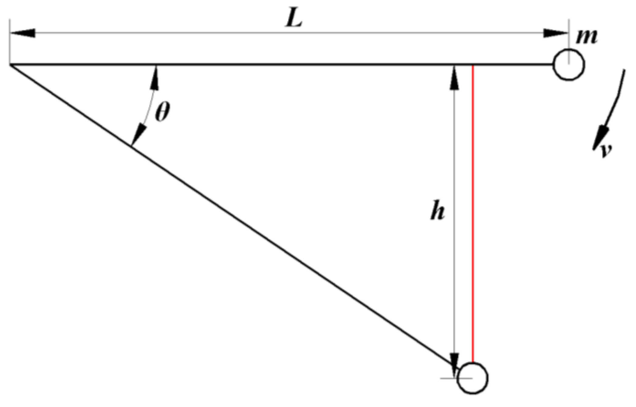
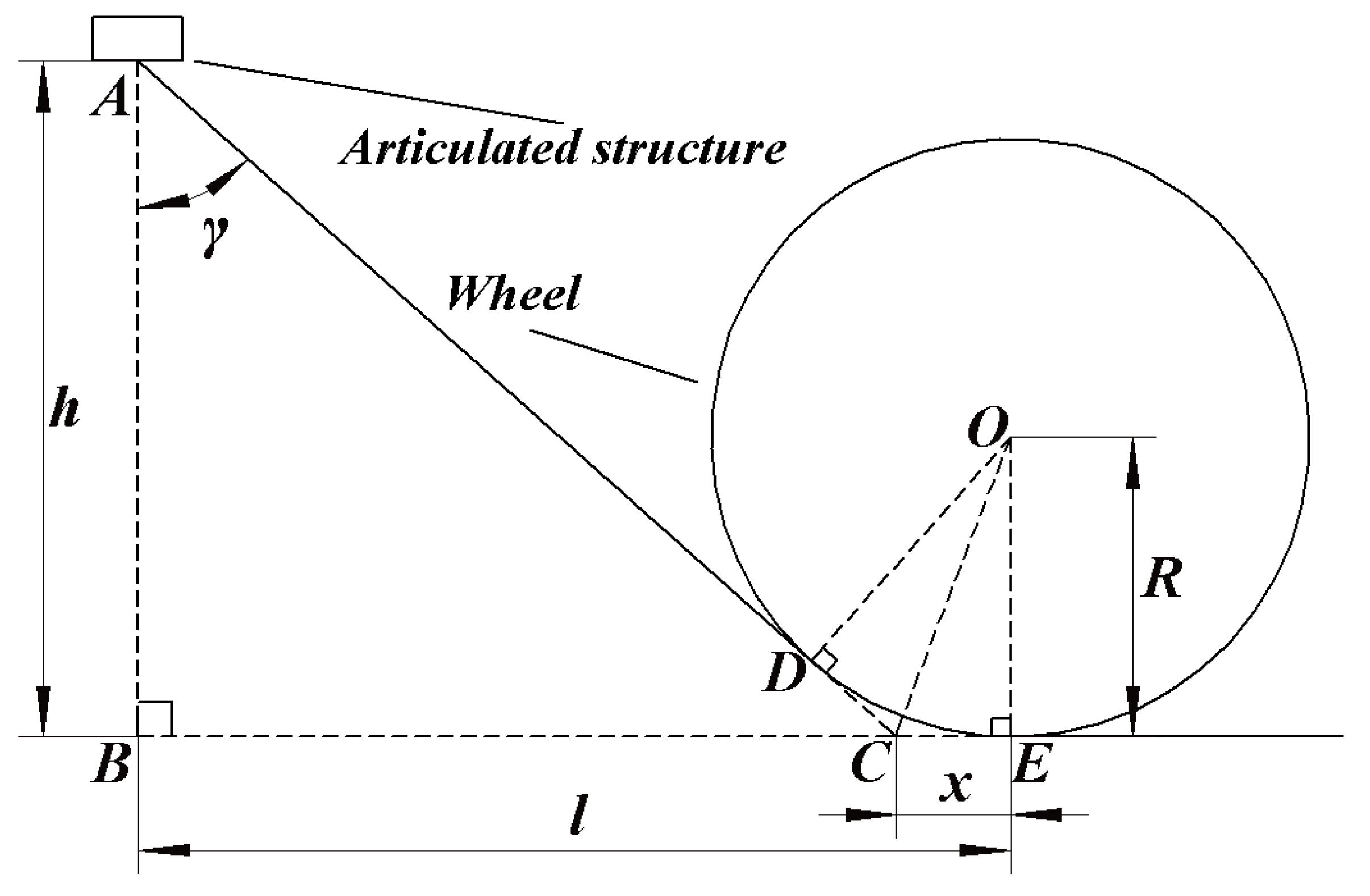
2.3.3. Theoretical Model of Ultimate Pitch Angle of Chassis

When an ordinary articulated chassis climbs over a slope, if there is a gap between the lowest point of the articulated structure and the road surface, the chassis can pass through the obstacle without pitching. However, the lowest point of the articulated structure often touches the road surface and cannot pass through due to the large slope. At this time, owing to its good road surface profile, the novel articulated structure can actively adjust the pitching motion of the front and rear frames in a certain range to ensure that the chassis can cross the slope smoothly. A schematic diagram of the theoretical model of the ultimate pitch angle of the chassis under this condition is shown in Figure 7. The articulated structure is simplified as a rectangle in the figure, and the tangent line of the wheel passes through the lowest point A of the rectangular center (the tangent point is D), and the tangent line through the lowest point E of the wheel intersects at point C. When the chassis climbs over a convex obstacle, if the top angle of the convex obstacle is less than the ultimate pitch angle, the bottom of the articulated structure touches the top of the slope, resulting in the separation of the wheels from the road surface in order that the wheels of the chassis cannot provide an effective driving force and ultimately cannot climb over the obstacle. Therefore, the theoretical limit pitch angle must be determined to provide a basis for judging whether the chassis needs the pitch profile when climbing over convex obstacles to improve the obstacle-climbing efficiency.
As shown in Figure 7, according to the geometric relationship, <COE = 45° − γ 2 . In ΔCOE, the following relationship exists:
tan ( 45 ° γ 2 ) = x R
Here, γ is the half value of the ultimate pitch angle;
x is the CE segment length;
R is the wheel radius.
In ΔABC, the following relationship exists:
tan γ = l x h
Here, l is the horizontal distance between the lowest point of the articulated structure and the lowest point of the wheel, and h is the height above ground at the lowest point of the articulated structure.
Equations (18) and (19) are simultaneously established, and tan γ 2 = y. The theoretical maximum ultimate pitch angle of the chassis β can be obtained as follows:
β = 2 γ = 4 arctan 2 ( R h ) + 4 h 2 8 h R + 4 l 2 2 ( l + R )
The values of the model parameters are R = 334 mm, h = 381.35 mm, and l = 857.84 mm, and the theoretical maximum ultimate pitch angle of the chassis β is 127.93° when substituted into Equation (20). According to Equation (11), the maximum pitch angle of articulated structure is 30.6°, and the theoretical minimum ultimate pitch angle of the chassis λ is 98.32°. Based on the above calculation results, when λ ≤ slope top angle ≤ β , the chassis can cross the slope through the pitch profile. When the slope top angle > β , the chassis can pass directly through the slope.

2.4. Kinematic Simulation Experiment of Articulated Structure

The chassis prototype model was established in SolidWorks and imported into ADAMS in Parasolid format. The ground environment was set to simulate the real road conditions, and the constraints and drives of each joint were added according to the actual movement of the chassis. The driving value of the rotary shaft rotation pair was added as 1°/s, and the contact relationship between the wheel and the road was added. The chassis model is shown in Figure 8. The simulation time was set to 360 s, and the number of simulation steps was 360. Figure 9 is a schematic diagram of the active pitch of the front and rear frames, Figure 9a,c is the horizontal position of the front and rear frames, Figure 9b is the pitch-down limit position of the front and rear frames, and Figure 9d is the lift-up limit position of the front and rear frames.

2.5. Chassis Working Condition Simulation Experiment

The terrain environment in the forest area is complex. Slopes and steep convex obstacles often appear. To facilitate the research, the chassis working conditions were simplified as climbing slopes, steep convex obstacles, and unilateral obstacles. On this basis, to verify the accuracy of the theoretical limit pitch angle model of the chassis and compare the driving performances of the novel articulated chassis and an ordinary four-wheel chassis under the three working conditions, ADAMS was used to establish the working conditions and perform simulations.

2.5.1. Climbing a Slope

ADAMS was used to establish a sloped road with a top angle of 150° (inclination angle of 15°), the chassis model was imported, relevant constraints were set and Fiala tyre model was selected to establish a simulation model of the chassis climbing over a slope, as shown in Figure 10. The sloped road was fixed with the ground, the contact between four wheels and the road was established. The contact material was set as channel steel, and the corresponding contact parameters were set by consulting relevant data and combining with the actual simulation environment [43,44,45]. Relevant parameters of chassis and simulation environment are listed in Table 2.
Slope-climbing simulation experiments were conducted for the ordinary chassis and the novel articulated forestry chassis. The rigid connection requirements of the ordinary chassis can be met by setting the drive of the rotating pair of the rotary shaft to 0 d. The rotational speed of the four wheels was set to 1.39 rev/s in order that the chassis could climb the slope at a constant speed. The simulation time was set to 10 s, and there were 500 simulation steps. A simulation diagram of the ordinary chassis climbing a slope with a top angle of 150° is shown in Figure 10b.
The novel articulated chassis for forestry can realize the pitching action of the front and rear frames through active control of the rotary shaft and then smoothly climb the slope. According to the kinematic model of the novel articulated structure established in Section 2.3.1 and the analysis of slope inclination, the rotary shaft must rotate 83° counterclockwise. The rotation angle control can be realized by adding a STEP drive function to the rotating pair of the rotary shaft. Based on the driving speed and distance, the driving function of the rotating pair of the rotary shaft is determined as Function (time) = STEP (time, 7.4, 0 d, 7.7, −83 d) + STEP (time, 7.9, 0 d, 8.1, 83 d). Figure 10c shows a simulation schematic diagram of the novel articulated chassis climbing over a slope with a top angle of 150°.
In addition, a slope road with a top angle of 120° (inclination angle of 30°) was established. According to the analysis of the theoretical model of the chassis limit pitch angle established in Section 2.3.3, at this time, λ ≤ the top angle of the slope ≤ β . A simulation model of the chassis climbing over the slope under these conditions was established, as shown in Figure 11. To prevent wheel slippage during chassis driving caused by the increase in the slope inclination angle, the static friction coefficient between wheels and road was set as 0.8, and other parameters remained unchanged.
Similar to the ordinary chassis climbing the slope, the drive of the rotating pair was set to 0 d, and the wheel speed was set to 1.39 rev/s in order that the chassis climbed the slope at a constant speed. The simulation time was set to 10 s, and the number of simulation steps was set to 500. A simulation schematic diagram of an ordinary chassis climbing a slope with a top angle of 120° is shown in Figure 11b.
Similar to the novel articulated chassis for forestry, according to the kinematic model of the novel articulated structure established in Section 2.3.1 and the analysis of slope inclination and based on the driving speed and distance, the driving function of the rotating pair of the rotary shaft was determined as Function (time) = STEP (time, 5.9, 0 d, 6.3, −90 d) + STEP (time, 6.7, 0 d, 7, 90 d). A simulation schematic diagram of the novel articulated chassis climbing a slope with a top angle of 120° is shown in Figure 11c.

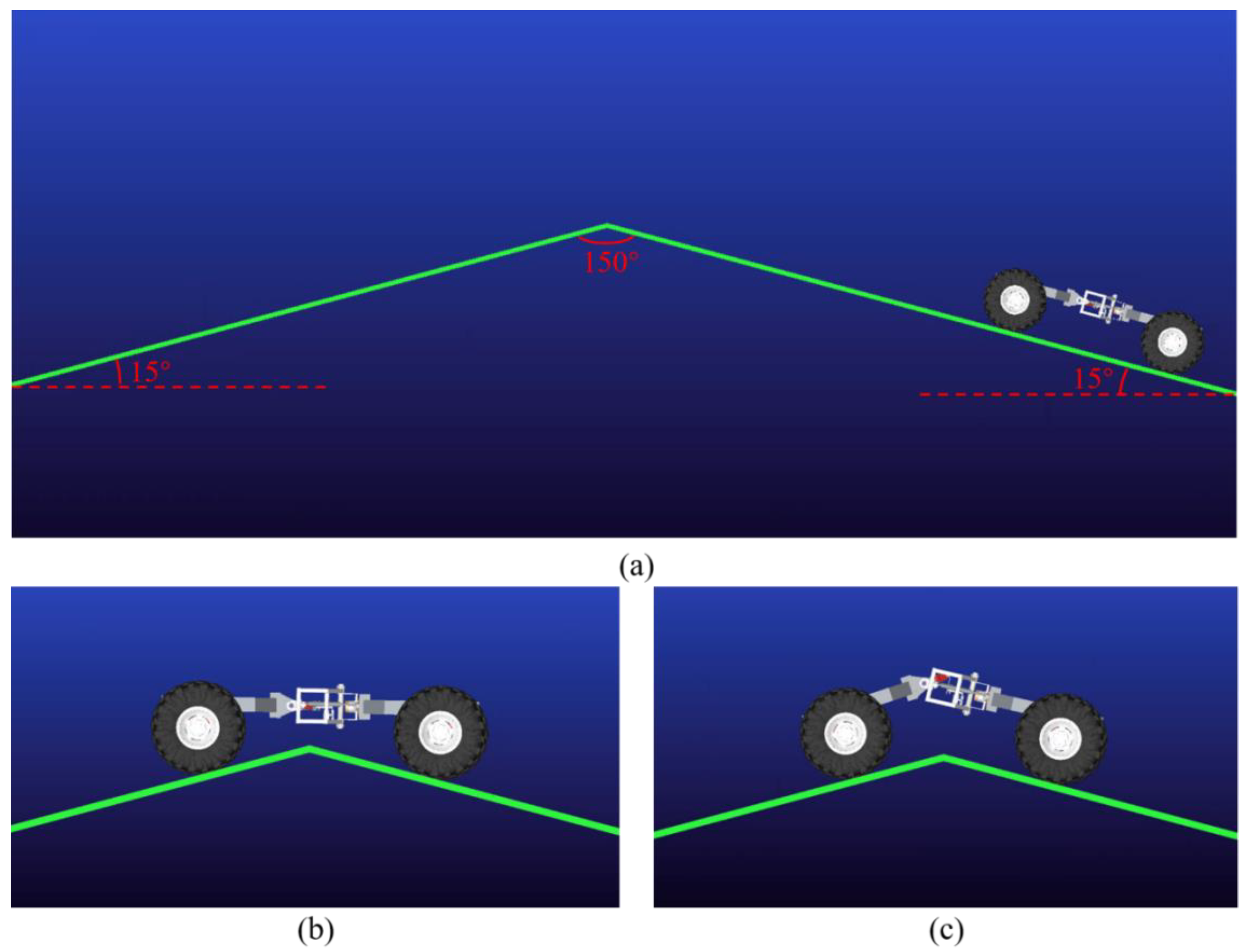
2.5.2. Steep-Convex-Obstacle Crossing

A vertical obstacle with a height of 250 mm was established in ADAMS. The chassis model was imported, and the same constraint parameters as in climbing the slope were set. Compared with climbing the slope, the initial distance between the chassis and the obstacle was smaller, and the chassis obstacle-crossing time increased (decreased) in the steep-convex-obstacle-crossing experiment if the wheel speed decreased (increased). To ensure that the simulation times of steep-convex-obstacle climbing and slope climbing are basically the same, the wheel speed was set as 0.83 rev/s, the simulation time was 6 s, and the number of steps was 300. Simulation experiments for an ordinary four-wheel chassis and the novel articulated chassis crossing a steep convex obstacle were established. Figure 12a shows a simulation schematic diagram of the steep-convex-obstacle crossing of an ordinary four-wheel chassis. In addition, for the steep-convex-obstacle crossing simulation experiment for the novel articulated chassis, active pitch of the front and rear frames was realized by controlling the rotary shaft, and then the steep convex obstacle was traversed by profiling. Based on the driving speed and obstacle distance, the driving function of the rotating pair was determined as Function (time) = STEP (time, 2.7, 0 d, 3.3, 45 d) + STEP (time, 3.3, 0 d, 3.45, −45 d) + STEP (time, 3.8, 0 d, 4.4, 45 d) + STEP (time, 4.4, 0 d, 4.6, −45 d). Figure 12b shows a simulation schematic diagram of the steep-convex-obstacle crossing of the novel articulated chassis.

2.5.3. Unilateral-Obstacle Crossing

A unilateral vertical obstacle with a height of 250 mm was established in ADAMS. The chassis model was imported, and the same constraint parameters were set as in climbing the slope. To ensure that the simulation times of unilateral-obstacle crossing and slope climbing were basically the same, the wheel speed was set as 0.83 rev/s, the simulation time was 6 s, and the number of steps was 300. Simulation experiments for an ordinary four-wheel chassis and the novel articulated chassis crossing a unilateral obstacle were performed. Figure 13a shows a simulation schematic diagram of the unilateral-obstacle crossing of an ordinary four-wheel chassis. In addition, for the novel articulated chassis, the front and rear frames were passively twisted when encountering the unilateral obstacle to realize profiling and to cross the unilateral obstacle. Figure 13b shows a simulation schematic diagram of the unilateral-obstacle crossing of the novel articulated chassis.

3. Results and Discussion

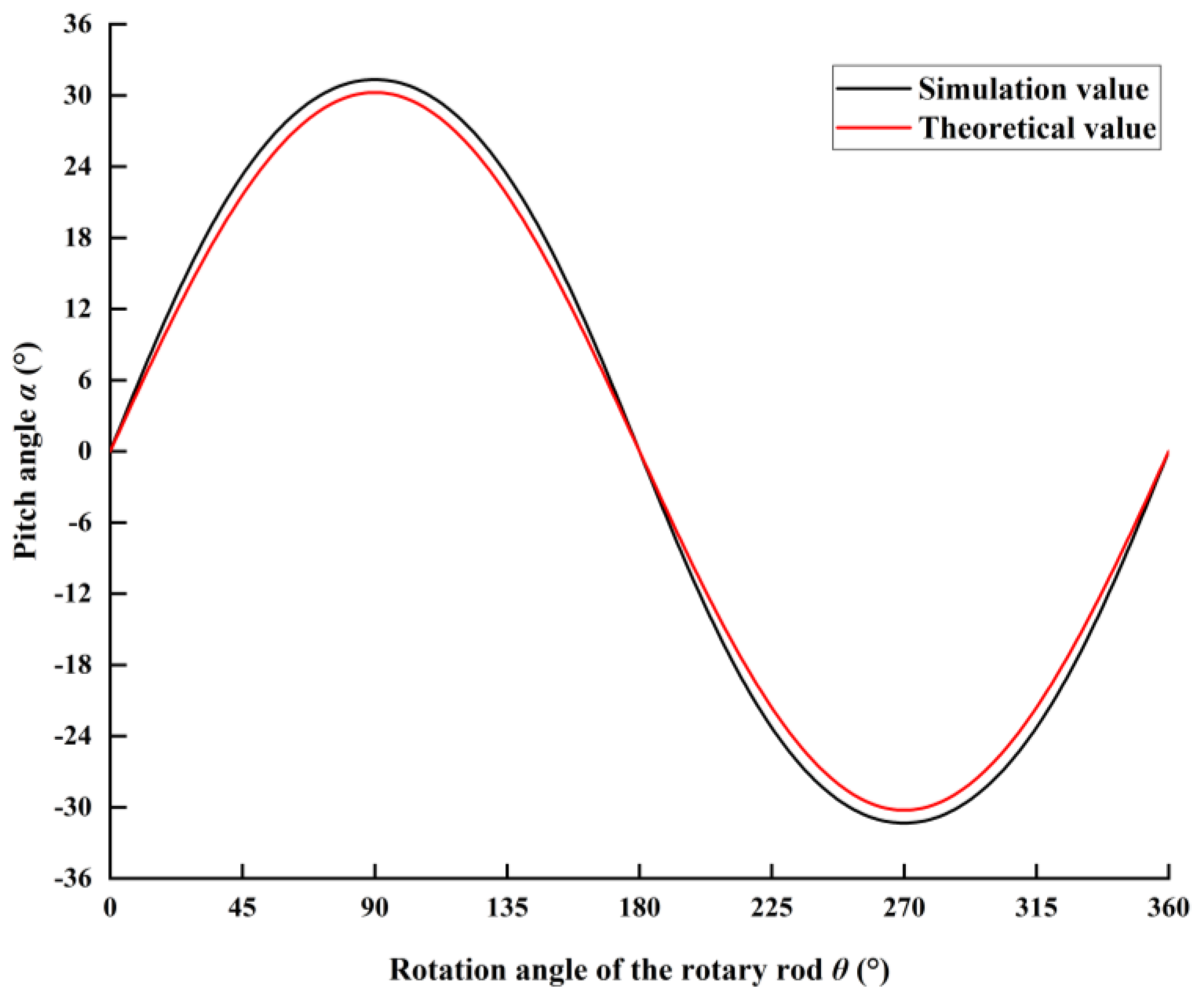
3.1. Analysis of Kinematics Simulation Experiment Results of Articulated Structure

MATLAB was used to analyze the relationship between the theoretical rotation angle of the rotary shaft and the pitching angle of the front and rear frames in Section 2.3.1 and compare it with the experimental data obtained by ADAMS simulation. The curve is shown in Figure 14. The rotation angle of the rotary shaft corresponds to the pitch angle one to one, and the pitch angle is not abrupt. In addition, the theoretical peak pitch angle occurs at the position where the rotation angle of the rotary shaft is 90° and its peak value is 30.24°. The ADAMS simulation results are similar to the theoretical analysis results. The ADAMS virtual simulation peak value is 31.33° and appears at the same position. The theoretical value is consistent with the simulation value, and the maximum error appears at the position where the rotation angle of the rotary shaft is 90°. It is not more than 1%, which verifies the accuracy of the theoretical model.

3.2. Analysis of Simulation Results of Chassis Working Conditions

3.2.1. Climbing the Slope

Figure 15 shows the center of gravity (COG) height variation curve of the articulated structure when the chassis passed over a slope with a top angle of 150°. The COG height of the ordinary and the novel chassis increases evenly during the period of 5.5–7.4 s, indicating that this is the climbing stage. The ordinary chassis reached the maximum height at 7.56 s, the height then decreased, and finally the chassis climbed the slope successfully. The novel chassis reached the maximum height at 7.66 s, the height then decreased, and finally the chassis successfully climbed the slope. The simulation results verify the theoretical model results in Section 2.3.3. When the top angle of the slope is greater than the theoretical maximum pitch angle of the chassis ( β ), the chassis can climb over the slope without adjusting the pitch angle.
Since the chassis has a symmetric structure and the wheels on both sides have the same contact with the road, only considering the force on the wheels on the left part of the chassis, the wheel force curve when the chassis crosses a slope with a top angle of 150° was obtained, as shown in Figure 16. When the wheel speed of the chassis is 1.39 rev/s and the ordinary chassis runs for 7.44–7.7 s, the force on the left front wheel is 0, indicating that the wheel is separated from the road at this time and the effective driving force is 0. Simultaneously, when the ordinary chassis runs to 7.72 and 8.3 s, the force on the front and rear wheels suddenly increases sharply, affecting the driving stability of the vehicle. When the novel chassis runs for 7.48–7.58 s, the effective driving force of the left front wheel is 0. Under this condition, the duration of the effective driving force of the front wheels of the novel chassis is 61.5% longer than the ordinary chassis, indicating that the road surface traction of the novel chassis is better, and each wheel can provide a sufficient driving force to make the chassis smoothly climb over the slope. The simulation results show that the novel articulated chassis has better road traction and drives more stably than the ordinary chassis.
Figure 17 shows the COG height variation curve of the articulated structure when the chassis passes over a slope with a top angle of 120°. The COG height of the ordinary chassis reaches the maximum at approximately 6.5 s; however, after a small fluctuation, it tends to remain unchanged, indicating that the ordinary chassis is stuck on the top of the slope and cannot climb the slope successfully. The COG height of the novel chassis reaches the maximum in approximately 6.5 s. After a period of fluctuation, it tends to decrease gradually and evenly, indicating that the novel chassis has climbed the slope. The simulation results verify the theoretical model results in Section 2.3.3. When the top angle of the slope is less than the theoretical maximum pitch angle of the chassis, the chassis must adjust the pitch angle to cross the slope.
Figure 18 shows the force on the wheels when the chassis crosses a 120° slope. The figure shows that the ordinary chassis reaches the top of the slope at 6.5 s. At this time, the contact force between the left front wheel and the road is only 1.5 kN. After 7 s, the force of the left front wheel is always 0, indicating that the front wheel and the road are separated from each other from this time, and the effective driving force is 0. The contact force between the rear wheel and the road is only 2–5 kN, and the chassis is stuck at the top of the slope due to the insufficient driving force. The novel chassis has good traction between the wheels and the road during the process, providing sufficient stable driving force to ensure that the chassis can climb the slope. Therefore, under the same output force, the novel articulated chassis for forestry has a better road profile than the ordinary chassis and can provide sufficient driving force to climb over the slopes.

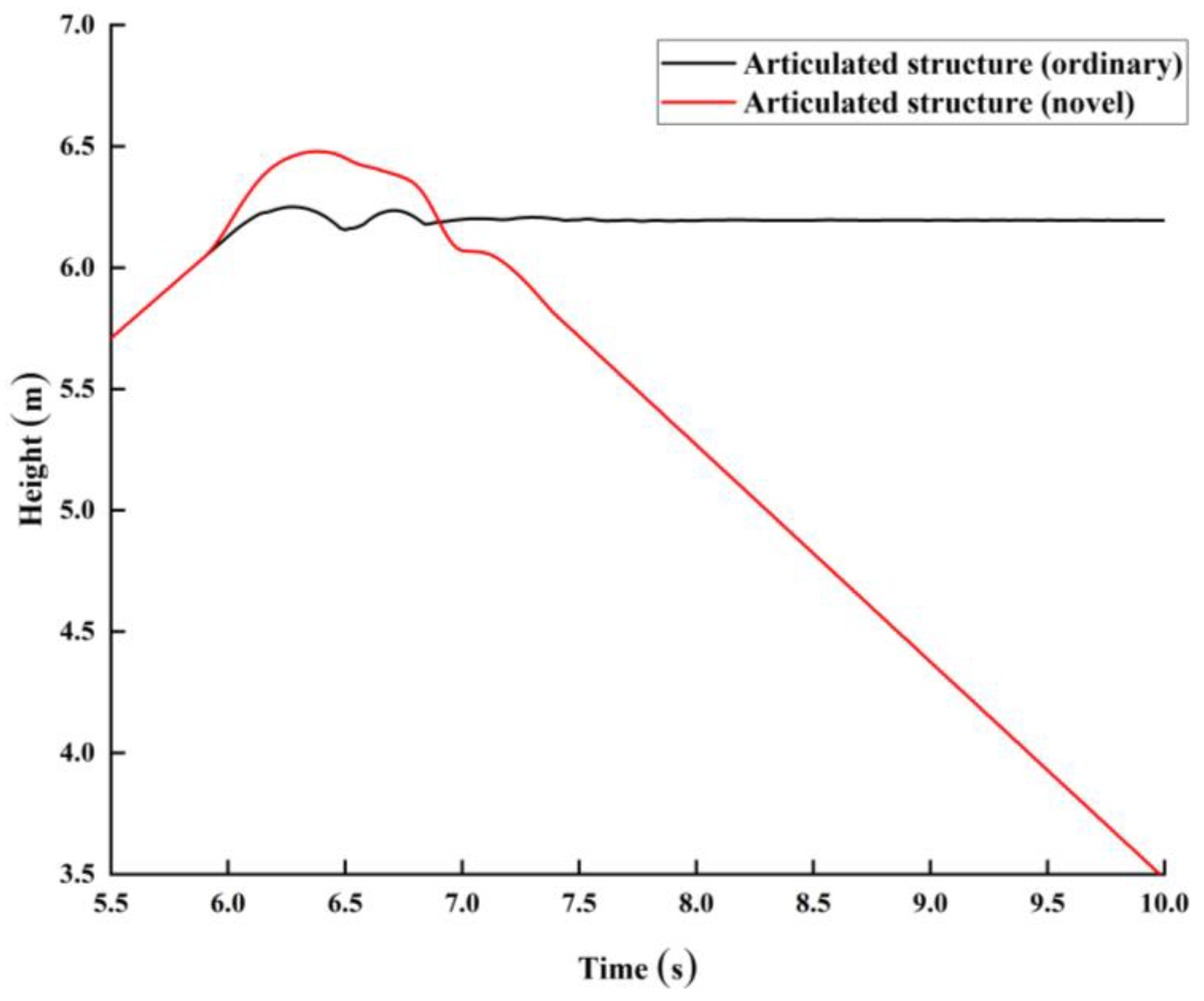
3.2.2. Steep-Convex-Obstacle Crossing

The variation curve of the frame COG height when the chassis climbs over a steep convex obstacle is shown in Figure 19. The COG height of the front frame of the ordinary chassis rises at approximately 2.7 s and remains unchanged for a period of time. Meanwhile, the COG height of the rear frame rises. At approximately 3.4 s, the COG of the front frame returns to the initial position, at which time the front frame completes the obstacle crossing. At approximately 3.8 s, the rear frame starts to cross the obstacle, and the process is similar to the front frame. After 4.6 s, the chassis passes the obstacle smoothly. However, the novel chassis can drive the articulated structure to make the front and rear frames pitch actively, making it possible for the front and rear frames to surmount the obstacle independently. The COG height of the rear (front) frame remains unchanged when the front (rear) frame surmounts the obstacle. Owing to the rigid articulated structure of the ordinary chassis, when the front frame crosses the obstacle, the rear frame has a corresponding lifting height, the wheels and road are not well contacted, and the chassis can easily overturn laterally. However, the novel chassis can cross obstacles independently. When the front (rear) frame crosses an obstacle, the rear (front) frame and the ground are always level, and the wheels have a good contact with the road, improving the lateral stability. The simulation results show that, for a steep convex obstacle, compared with the ordinary chassis, the active pitch function of the novel chassis can ensure that the wheels have a good contact with the road and the load can pass the obstacle smoothly.
The chassis has a symmetric structure and the wheels on both sides have the same contact with the road. Therefore, only considering the force on the wheels on the left part of the chassis, the force curve of the left wheels when the chassis crosses the steep convex obstacle is shown in Figure 20. The front frame of the ordinary chassis crosses the obstacle at 2.7 s, and the rear wheel provides the driving force for the crossing. When the rear frame crosses the obstacle, the contact force of the rear wheel in a short time is 10 kN. The front frame of the novel chassis surmounts the obstacle at 2.7 s, and the rear wheels provide driving force for surmounting the obstacle. When the rear frame surmounts the obstacle, the contact force of the rear wheel in a short time is 17.3 kN. Compared with the ordinary chassis, the rear wheels of the novel chassis can provide a greater driving force, indicating that the novel chassis has good road traction. The simulation results show that the novel chassis has good road traction performance compared with the ordinary chassis when encountering steep convex obstacles, ensuring that the chassis can surmount obstacles smoothly.

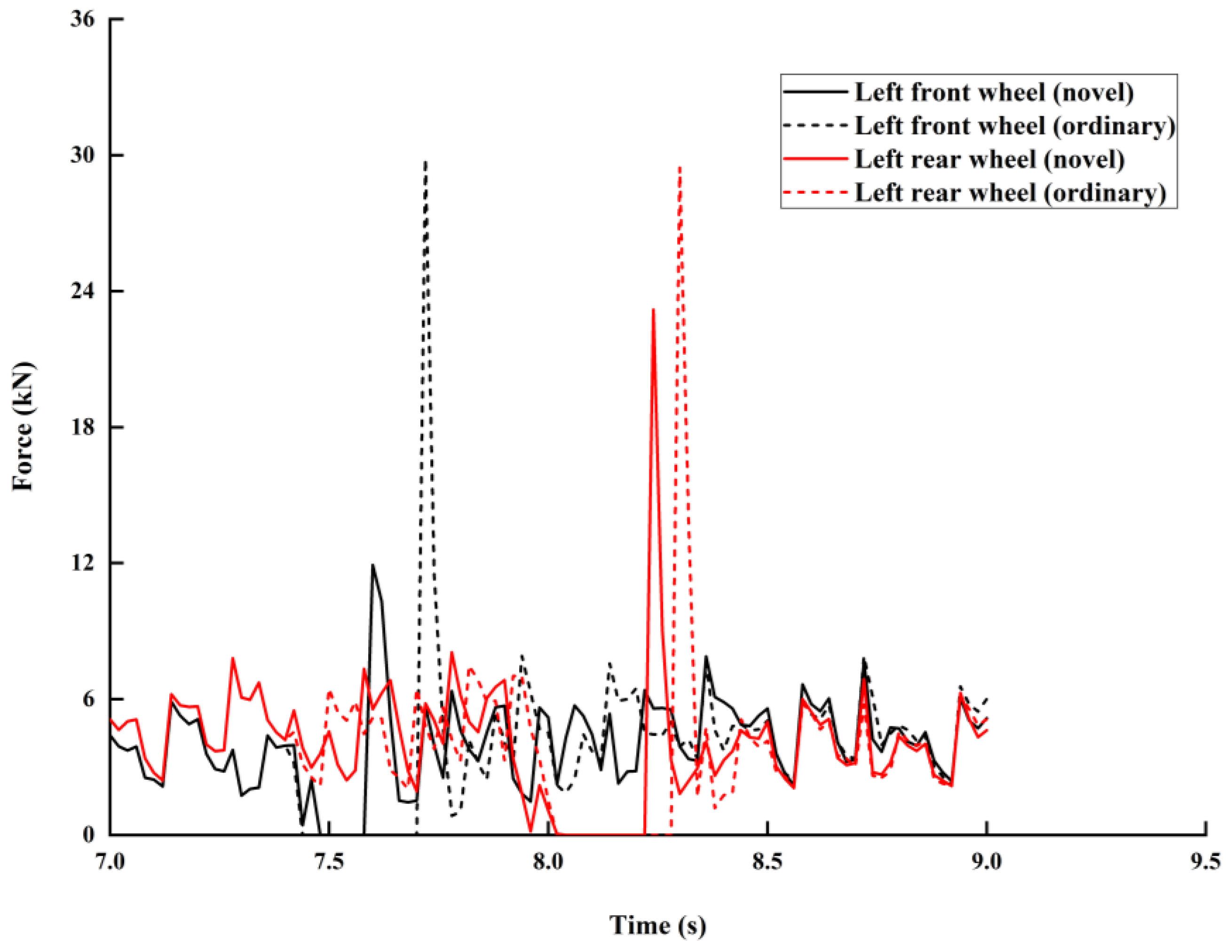
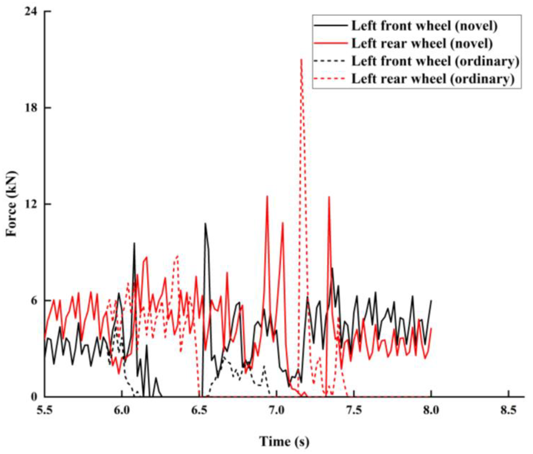
3.2.3. Unilateral-Obstacle Crossing

The variation curve of the frame COG height when the chassis climbs over a unilateral obstacle is shown in Figure 21. The COG height of the front and rear frames of the ordinary chassis increases and remains unchanged at 2.6 s and decreases at 4.8 s, indicating that the chassis has completed crossing the obstacles. The front frame of the novel chassis crosses the obstacle at 2.6 s, reaching the peak point at 2.74 s, and the COG height of the front frame remains unchanged until 3.5 s. The rear frame starts to cross the obstacle at 3.1 s and reaches the peak point at 3.34 s. The COG height of the rear frame remains unchanged until 4.1 s, and the chassis crosses the obstacle at 4.4 s. When the novel chassis climbs over a unilateral obstacle, the change law is similar to the steep-convex-obstacle crossing. The front and rear frames cross the obstacles independently. In the unilateral-obstacle crossing of the ordinary chassis, the COG height variations of the front and rear frames are the same since the chassis has no longitudinal torsional degree-of-freedom along the body. In addition, under the same simulation environment, the unilateral-obstacle-crossing time of the novel chassis is shorter than the ordinary chassis, indicating that the ordinary chassis has a high wheel idling rate and insufficient driving force. The simulation results show that, compared with the ordinary chassis, the novel chassis has good road traction when encountering unilateral obstacles, ensuring that the chassis can pass unilateral obstacles successfully.
The force variation law of each wheel is different when the chassis surmounts obstacles unilaterally, and the force curve of each wheel of the chassis is shown in Figure 22. The front frame of the ordinary chassis surmounts obstacles in 2.6 s. Only the right front wheel and left rear wheel have contact force. The contact force of the left front wheel is 0 in 2.6–3.4 s, and the contact force of the right rear wheel is 0 in 2.6–3.2 s. They cannot provide an effective driving force. During the obstacle crossing of the rear frame, the variation trend of the wheel force is similar to the front frame. When the novel chassis crosses obstacles on one side, each wheel has contact force with the road, providing a continuous and effective driving force for the chassis to pass obstacles. The simulation results show that, compared with the ordinary chassis, the novel chassis can provide a continuous and stable effective driving force for surmounting obstacles due to its good road profile, and it has superior performance in surmounting obstacles.

4. Conclusions

(1)
According to the principle of multiple-degree-of-freedom profiling, a novel articulated chassis was designed for forestry. The innovative articulated structure realizes active pitching, active deflection, and passive torsion of the front and rear frames and meets the requirements of profiling driving on uneven roads.
(2)
Through a kinematics and dynamics analysis of the articulated structure, a theoretical model of the relationship between the rotation angle of the rotary shaft and the pitch angle of the front and rear frames was established. The quantitative relationship between the output torque of the servo motor and the angular acceleration and angle of the terminal pitch plate was determined, making it possible to control the leaning and pitching motion of the front and rear frames by adjusting the output torque of the servo motor. The theoretical limit pitch angle of the chassis was determined, providing a judgment basis for chassis profiling obstacle crossing.
(3)
ADAMS was used to establish a forest chassis simulation model, and a kinematics simulation experiment for the articulated structure was conducted. A comparison between simulation and theoretical results shows that the maximum error occurs at the position where the rotation angle of the rotary shaft is 90° and less than 1%, demonstrating the accuracy of the theoretical model.
(4)
The complex terrain environment of a forest area was simplified into three working conditions: Climbing over slopes, steep convex obstacles, and unilateral obstacles. The three working conditions were established in ADAMS, and a simulation experiment was performed. For climbing over a slope at a wheel speed of 1.39 rev/s, the duration of the effective driving force of the front wheel of the novel chassis was 61.5% longer than an ordinary chassis. For steep-convex-obstacle crossing, compared with an ordinary chassis, the active pitch function of the novel chassis ensured that the wheels had a good contact with the road and carried the load past the obstacles smoothly. For unilateral-obstacle crossing, the novel chassis provided a continuous and stable effective driving force for obstacle crossing due to its good road profile. The research results provide guidance for the mechanization of forestry equipment and a theoretical and technical foundation for research on special forestry equipment chassis.

Author Contributions

Data curation, Z.X.; Writing–original draft, X.L.; Writing–review & editing, Y.Z.; Supervision, Y.Z.; Funding acquisition, Y.Z. All authors have read and agreed to the published version of the manuscript.

Funding

This research was funded by the National Natural Science Foundation of China (grant no. 52102422), the Fujian Province Natural Science Foundation of China (grant no. 2021J05025), the Research Funds for Young Teachers of Fujian Education Department (grant no. JAT190137), and the Research Fund for Young Teachers of Fujian Agriculture and Forestry University (grant no. 71201800207).

Institutional Review Board Statement

Not applicable.

Informed Consent Statement

Not applicable.

Data Availability Statement

Public datasets are available from the authors.

Conflicts of Interest

The authors declare that they have no known competing financial interest or personal relationships that could have appeared to influence the work reported in this paper.

References

  1. Pan, J. Prospect of agricultural Mechanization development in hilly areas. Agric. Dev. Equip. 2020, 6, 68, 70. (In Chinese) [Google Scholar]
  2. Song, J.W.; Liu, H.X. Accelerate the breakthrough of agricultural mechanization development bottleneck in hilly and mountainous areas. China Agric. Mech. 2010, 16–19. (In Chinese) [Google Scholar]
  3. Bergerman, M.; Billingsley, J.; Reid, J.; van Henten, E. Robotics in agriculture and forestry. In Springer Handbook of Robotics; Springer: Cham, Switzerland, 2016; pp. 1463–1492. [Google Scholar]
  4. Khot, L.R.; Tang, L.; Steward, B.L.; Han, S. Sensor fusion for improving the estimation of roll and pitch for an agricultural sprayer. Biosyst. Eng. 2008, 101, 13–20. [Google Scholar] [CrossRef]
  5. Vidoni, R.; Bietresato, M.; Gasparetto, A.; Mazzetto, F. Evaluation and stability comparison of different vehicle configurations for robotic agricultural operations on side-slopes. Biosyst. Eng. 2015, 129, 197–211. [Google Scholar] [CrossRef]
  6. Liu, P.Y.; Wang, C.Y.; Li, H.T.; Zhang, M.; Wei, W.; Zhang, S. Design and experiment of dynamic leveling chassis for agricultural profile walking in hilly areas. Trans. Chin. Soc. Agric. Mach. 2018, 49, 74–81. (In Chinese) [Google Scholar]
  7. Gao, Q.M.; Pan, D.; Zhang, X.; Deng, F.Y.; Huang, D.H.; Wang, L.Q. Design and Simulation of full track modular unmanned agricultural power chassis. Trans. Chin. Soc. Agric. Mach. 2020, 51, 561–570. (In Chinese) [Google Scholar]
  8. Wang, Y.; Qin, H.; Xu, S.B.; Gou, Y.F.; Li, H.T. Research and trial production of all terrain profiling walking vehicle. J. Dalian Univ. Technol. 2011, 51, 84–87. (In Chinese) [Google Scholar]
  9. Agheli, M.; Nestinger, S.S. Study of the foot force stability margin for multi-legged/wheeled robots under dynamic situations. In Proceedings of the 2012 IEEE/ASME 8th IEEE/ASME International Conference on Mechatronic and Embedded Systems and Applications, Suzhou, China, 8–10 July 2012; IEEE: New York, NY, USA, 2012; pp. 99–104. [Google Scholar]
  10. Wang, Z.; Ding, X.; Rovetta, A.; Giusti, A. Mobility analysis of the typical gait of a radial symmetrical six-legged robot. Mechatronics 2011, 21, 1133–1146. [Google Scholar] [CrossRef]
  11. Cheng, C.; Cebon, D. Improving roll stability of articulated heavy vehicles using active semi-trailer steering. Veh. Syst. Dyn. 2008, 46, 373–388. [Google Scholar] [CrossRef]
  12. Ismoilov, A.; Sellgren, U.; Andersson, K.; Löfgren, B. A comparison of novel chassis suspended machines for sustainable forestry. J. Terramechanics 2015, 58, 59–68. [Google Scholar] [CrossRef]
  13. Reiter, J.; Boehringer, K.F.; Campbell, M. MEMS control moment gyroscope design and wafer-based spacecraft chassis study. In Micromachined Devices and Components V; SPIE—The International Society for Optical Engineering: Washington, DC, USA, 1999; p. 3876. [Google Scholar]
  14. Alamdari, A.; Krovi, V. Active reconfiguration for performance enhancement in articulated wheeled vehicles. In Dynamic Systems and Control Conference; American Society of Mechanical Engineers: New York, NY, USA, 2014. [Google Scholar]
  15. Zhao, K.; Liu, J.H.; Huang, Q.Q.; Hao, S.; Dian, W. Optimization design and obstacle overcoming performance simulation analysis of forestry parallel articulated chassis. J. Beijing For. Univ. 2018, 40, 131–140. (In Chinese) [Google Scholar]
  16. Carabin, G.; Gasparetto, A.; Mazzetto, F.; Vidoni, R. Design, implementation and validation of a stability model for articulated autonomous robotic systems. Robot. Auton. Syst. 2016, 83, 158–168. [Google Scholar] [CrossRef]
  17. Smith, T.; Chavez, D. A Practical Comparison of motion planning techniques for robotic legs in environments with obstacles. In Proceedings of the 2009 Third IEEE International Conference on Space Mission Challenges for Information Technology, Pasadena, CA, USA, 19–23 July 2009; pp. 155–162. [Google Scholar]
  18. Li, L.; Zhao, H.; Li, B.H. Simulation study on obstacle crossing performance of articulated crawler submarine mining vehicle. Comput. Simul. 2008, 25, 195–199. (In Chinese) [Google Scholar]
  19. Edlund, J.; Keramati, E.; Servin, M. A long-tracked bogie design for forestry machines on soft and rough terrain. J. Terramech. 2013, 50, 73–83. [Google Scholar] [CrossRef]
  20. Liu, P.Y.; Peng, F.J.; Li, H.T.; Wang, Z.Z.; Wei, W.J.; Zhao, J.P. Design and experiment of adaptive leveling chassis for agriculture in hilly areas. Trans. of the Chin. Soc. Agric. Mach. 2017, 48, 42–47. (In Chinese) [Google Scholar]
  21. Liu, P.Y.; Ke, C.P.; Ke, T.; Li, H.T.; Wei, W.J.; Zhao, C. Design and experiment of pretesting active leveling chassis for agriculture in hilly areas. Transactions of the Chin. Soc. Agric. Mach. 2020, 51, 371–378. (In Chinese) [Google Scholar]
  22. Liu, P.Y.; Li, H.T.; Zhang, S.Y.; Wei, W. Theoretical Analysis and Experiment of All Terrain Adaptive Locomotion Vehicle; Editorial Office of Transactions of the Chinese Society of Agricultural Engineering: Beijing, China, 2012; p. 28. [Google Scholar]
  23. Zhang, N. Analysis of swing frame structure of mining special vehicle based on SimSolid. Coal Mine Mech. Electr. 2020, 41, 59–62. (In Chinese) [Google Scholar]
  24. Hao, Z.J. Analysis and Discussion on Swing Structure of Mining Articulated Vehicle. Coal Mine Mach. 2020, 41, 89–92. (In Chinese) [Google Scholar]
  25. Moreno, G.; Manenti, V.; Guerero, G.; Nicolazzi, L.; Vieira, R.; Martins, D. Stability of heavy articulated vehicles: Effect of load distribution. Transp. Res. Procedia 2018, 33, 211–218. [Google Scholar] [CrossRef]
  26. Cojocaru-Greblea, T.; Bontos, M.D.; Vasiliu, N.; Dobre, A. Redundant Steering Systems for Articulated Vehicles. Int. Multidiscip. Sci. GeoConference SGEM 2017, 17, 497–504. [Google Scholar]
  27. Pijuan, J.; Comellas, M.; Nogués, M.; Roca, J.; Potau, X. Active bogies and chassis levelling for a vehicle operating in rough terrain. J. Terramech. 2012, 49, 161–171. [Google Scholar] [CrossRef]
  28. Zhu, Y. Design and Analysis of Wheel-Leg Variable Amplitude and 3-DOF Articulated Forest Chassis; Beijing Forestry University: Beijing, China, 2018. (In Chinese) [Google Scholar]
  29. Zhu, Y.; Kan, J.M. Design and obstacle overcoming performance analysis of 3-DOF articulated forest chassis. J. Beijing For. Univ. 2016, 38, 126–132. (In Chinese) [Google Scholar]
  30. Zhu, Y.; Kan, J.; Li, W.; Kang, F. A novel forestry chassis with an articulated body with three degrees of freedom and installed luffing wheel-legs (FC-3DOF&LW). Adv. Mech. Eng. 2018, 10, 1–10. (In Chinese) [Google Scholar]
  31. Zhu, Y.; Kan, J. Prediction of the lateral stability of a forestry chassis with an articulated body and fitted with luffing wheel-legs. Biosyst. Eng. 2022, 224, 143–160. [Google Scholar] [CrossRef]
  32. Zhu, Y.; Kan, J.; Li, W.; Kang, F. Strategies of traversing obstacles and the simulation for a forestry chassis. Int. J. Adv. Robot. Syst. 2018, 15, 68–73. [Google Scholar] [CrossRef] [Green Version]
  33. San, T.; Ishii, Y. A study on current state of forest resources and forest policy in myanmar. Trans. Meet. Hokkaido Branch Jpn. For. Soc. 2018, 46, 107–110. [Google Scholar]
  34. Guan, Y.X. Analysis of influencing factors and countermeasures of forest coverage in Fujian Province. For. Surv. Des. 2015, 10–13. (In Chinese) [Google Scholar]
  35. Zhang, L.J.; You, T.G.; Lin, L.X.; Chen, S.Z.; Huang, Y. Study on the relationship between air quality and forest coverage in Fujian Province. Wuyi Sci. 2018, 34, 144–150. (In Chinese) [Google Scholar]
  36. Fan, J.F.; Huang, S.C.; Mei, E.Z.; Tang, X.N. Motion and simulation analysis of universal joint coupling based on cross shaft. Mach. Des. 2021, 38, 91–96. (In Chinese) [Google Scholar]
  37. Sun, T.; Xiang, X.; Su, W.; Wu, H.; Song, Y. A transformable wheel-legged mobile robot: Design, analysis and experiment. Robot. Auton. Syst. 2017, 98, 30–41. (In Chinese) [Google Scholar] [CrossRef]
  38. Dobretsov, R.Y.; Voinash, S.A.; Sokolova, V.A.; Krivonogova, A.S.; Pushkov, Y.L.; Andronov, A.V. Power distribution mechanism for the transmission of forest tracked and wheeled vehicles. In Journal of Physics: Conference Series; IOP Publishing: Bristol, UK, 2020; Volume 1679, p. 042046. [Google Scholar]
  39. Franceschetti, B.; Lenain, R.; Rondelli, V. Comparison between a rollover tractor dynamic model and actual lateral tests. Biosyst. Eng. 2014, 127, 79–91. [Google Scholar] [CrossRef]
  40. Zhao, T.W.; Xue, Y.H.; Xue, Y.H.; Bao, Q.Q. Kinematics and Dynamics Simulation Analysis of Wheel Assembly Manipulator for Large Heavy-Duty Vehicle Based on ADAMS. J. Mach. Des. 2021, 38, 27–31. (In Chinese) [Google Scholar]
  41. Huang, H.S.; Li, T.; Liu, J.H. Dynamic Modeling and Simulation Analysis of 6-HUS Parallel Moving Platform. J. Beijing For. Univ. 2015, 37, 143–150. (In Chinese) [Google Scholar]
  42. ElMadany, M.M.; Dokainish, M.A.; Allan, A.B. Ride dynamics of articulated vehicles—A literature survey. Veh. Syst. Dyn. 1979, 8, 287–316. [Google Scholar] [CrossRef]
  43. Alamdari, A.; Krovi, V.N. Design of articulated leg–wheel subsystem by kinetostatic optimization. Mech. Mach. Theory 2016, 100, 222–234. [Google Scholar] [CrossRef]
  44. Han, D.T.; Liu, J.H.; Wang, D.; Li, D.W. Research on Obstacle Crossing and Position Optimization of a Double-cylinder wheel Leg of Forest Active Gait Chassis. J. Beijing For. Univ. 2018, 40, 117–124. (In Chinese) [Google Scholar]
  45. Alamdari, A.; Zhou, X.; Krovi, V.N. Kinematic modeling, analysis and control of highly reconfigurable articulated wheeled vehicles. In Proceedings of the International Design Engineering Technical Conferences and Computers and Information in Engineering Conference, Portland, OR, USA, 4–7 August 2013; American Society of Mechanical Engineers: New York, NY, USA, 2013. [Google Scholar]
Figure 1. Schematic diagram of the novel articulated chassis for forestry: (1) Front frame, (2) rear frame, (3) wheel, (4) three-degree-of-freedom articulated structure, and (5) independent suspension.
Sustainability 14 16118 g001
Figure 2. Schematic diagram of three-degree-of-freedom articulated structure: (a) General schematic diagram: (1) front frame, (2) pitch plate, (3) frame, (4) rotary shaft, (5) steering hydraulic cylinder, (6) torsion connector, (7) rear frame, (8) steering hydraulic cylinder, (9) meshing gear, (10) servo motor, (11) ball joint pair, and (12) slider; (b) horizontal position; (c) lift-up limit position; (d) horizontal position; and (e) pitch-down limit position.
Sustainability 14 16118 g002
Figure 3. Structural diagram of rotary shaft: (a) Equivalent model described in red; (b) corresponding geometry.
Sustainability 14 16118 g003
Figure 4. Position diagram of the center point of the ball head at the end of the rotary shaft: (a) Equivalent model described in red; (b) corresponding geometry.
Sustainability 14 16118 g004
Figure 5. Movement diagram of ball head center: (a) Spatial movement diagram of ball head center; (b) displacement diagram of ball head in yoz-plane; and (c) displacement diagram of ball head in xoy-plane.
Sustainability 14 16118 g005
Figure 6. Schematic diagram of ball head movement track of rotary shaft.
Sustainability 14 16118 g006
Figure 7. Schematic diagram of the ultimate pitch angle model.
Sustainability 14 16118 g007
Figure 8. Schematic diagram of chassis model in ADAMS.
Sustainability 14 16118 g008
Figure 9. Schematic diagram of active pitch of front and rear frames. (a) Horizontal position (rotary shaft θ = 0 ° ); (b) pitch-down limit position (rotary shaft θ = 90 ° ); (c) horizontal position (rotary shaft θ = 180 ° ); and (d) lift-up limit position (rotary shaft θ = 270 ° ).
Sustainability 14 16118 g009
Figure 10. Sloped road simulation model with top angle of 150° (inclination angle of 15°): (a) Sloped road; (b) simulation schematic diagram of ordinary chassis climbing the slope; and (c) simulation schematic diagram of the novel articulated chassis climbing the slope.
Sustainability 14 16118 g010
Figure 11. Sloped road simulation model with top angle of 120° (inclination angle of 30°): (a) Sloped road; (b) simulation schematic diagram of ordinary chassis climbing the slope; and (c) simulation schematic diagram of the novel articulated chassis climbing the slope.
Sustainability 14 16118 g011
Figure 12. Simulation diagram of steep-convex-obstacle crossing: (a) Simulation diagram of steep-convex-obstacle crossing of ordinary chassis; (b) simulation diagram of steep-convex-obstacle crossing of novel articulated chassis.
Sustainability 14 16118 g012
Figure 13. Simulation diagram of unilateral-obstacle crossing: (a) Simulation diagram of unilateral-obstacle crossing of ordinary chassis; (b) simulation diagram of unilateral-obstacle crossing of novel articulated chassis.
Sustainability 14 16118 g013
Figure 14. Variation law of pitch angle versus rotation angle of rotary shaft.
Sustainability 14 16118 g014
Figure 15. Variation curves of COG height of articulated structure over slope (top angle: 150°).
Sustainability 14 16118 g015
Figure 16. Force curves of left wheels over slope (top angle: 150°).
Sustainability 14 16118 g016
Figure 17. Variation curves of COG height of articulated structure over slope (top angle: 120°).
Sustainability 14 16118 g017
Figure 18. Force curves of left wheels over slope (top angle: 120°).
Sustainability 14 16118 g018
Figure 19. Variation curves of frame COG height of steep-convex-obstacle crossing.
Sustainability 14 16118 g019
Figure 20. Force curves of left wheels of steep-convex-obstacle crossing.
Sustainability 14 16118 g020
Figure 21. Variation curves of frame COG height of unilateral-obstacle crossing.
Sustainability 14 16118 g021
Figure 22. Force curves of wheels of unilateral-obstacle crossing: (a) Ordinary chassis; (b) novel chassis.
Sustainability 14 16118 g022
Table 1. Table of rotary shaft parameters.
ParameterValue
L1 (mm)75.09
L2 (mm)25
L3 (mm)42.5
α 1 (°)150
α 2 (°)30
Table 2. Chassis and simulation-environment-related parameters.
ParameterValue
Stiffness coefficient (N/mm)100,000
Force index1.5
Damping coefficient (N-s/mm)10,000
Penetration depth (mm)0.001
Coefficient of static friction0.3
Coefficient of dynamic friction 3
Static friction velocity (mm/s)0.1
Dynamic friction velocity (mm/s)10
Chassis length (mm)2260
Chassis width (mm)1580
Wheel diameter (mm)660
Wheel width (mm)160
Chassis mass (kg)510
Publisher’s Note: MDPI stays neutral with regard to jurisdictional claims in published maps and institutional affiliations.

