Article

Numerical Optimization of the Dendritic Arm of a Radial Gate Based on Stability and Light Weight

1
Power China Huadong Engineering Corporation Limited, Hangzhou 311122, China
2
Yellow River Engineering Consulting Co., Ltd., Zhengzhou 450003, China
3
Hangzhou Sennaier Engineering Technology Co., Ltd., Hangzhou 310014, China
4
College of Water Resources and Architectural Engineering, Northwest A&F University, Xianyang 712100, China
*
Author to whom correspondence should be addressed.
Sustainability 2022, 14(24), 16507; https://doi.org/10.3390/su142416507
Submission received: 24 October 2022 / Revised: 2 December 2022 / Accepted: 7 December 2022 / Published: 9 December 2022
(This article belongs to the Section Hazards and Sustainability)

Abstract

:
A new dendritic arm structure was proposed to achieve the stability and lightness of a large-scale radial gate arm. The arm structure was arranged in accordance with the current gate design specifications for steel. The optimization aims were to achieve the highest possible overall structural stability and the lowest possible weight. As the failure criterion for the entire structure, the simultaneous instability of the trunks and branches of the dendritic arm was considered. The constraints of strength, stiffness, and stability were identified, and an optimization model of a dendritic arm with two branches was established. A geometric and material nonlinear buckling analysis and optimization solution was implemented for the dendritic arm with a different radius, type, and unit rigidity ratios. Compared to a conventional radial gate structure with two arms, the Y-type dendritic arm structure was lighter and more stable. The optimal dendritic arm had the following parameter settings: the angle ratio between two branches and two arms was [1.92, 2.04], the unit rigidity ratio between the trunk and branch was [5.33, 6.02], the length ratio between the branch and trunk was [0.96, 1.09], the height ratio of the trunk and branch was 1.805, and the flange thickness ratio of the trunk and branch was 1.405. In this case, the overall buckling load ratio between the dendritic arm and two arms was [2.50, 4.34], and the material saving rate was [37, 53] (%). Within the aforementioned parameters, the Y-type dendritic arm performed better overall. Moreover, the radius of the radial gate had minimal influence on the shape and mechanical properties of the Y-type dendritic arm structure. This paper proposes a dendritic arm that can be utilized in most radial gate projects.

1. Introduction

With the rapid development of water conservancy and hydropower and the continuous improvement of the manufacturing level of metal structures, a hydraulic hub focuses on a high head, a large orifice, and a large discharge, and the load acting on the gate, the size, and the self-weight continues to grow. Examples include the gate of Wuqiangxi hydropower station with the largest orifice size of 19 × 23 (m2), the steel gate of Xiluodu hydropower station with the maximum self-weight of 702 tons, and the steel gate of Xiaolangdi hydropower station with the highest water head up to 160 m in China.
Large-scale radial gates present numerous new structural designs, hoist type selection, and safe operation challenges. Designing large-scale hydraulic steel gates to ensure high overall stiffness and light weight as well as flexible opening and closing is a pressing problem. Traditional radial gate arms have either two or three arms; although the manufacturing process for two arms is simpler, the stability under the same material consumption is greater with three arms. However, the gate’s overall size and stiffness are subpar with three arms. Furthermore, while the overall stiffness of gates with three arms is increased, the dispersed use of arm materials reduces the overall structural stability. Consequently, the proportion of crashes increases [1].
For its shape and mechanical properties, scholars at home and abroad have conducted much research on tree structures. For example, German architect Ferré Otto introduced the concept of the tree structure, demonstrated that it is more effective than conventional columnar structures using the BIC power quotient method, and implemented it for the first time in the design of the Stuttgart airport terminal [2,3]. Because of its large bearing area, high structural stability, light structure, and economical material, tree structures are widely used in various construction projects, and these exceptional benefits are also required for hydraulic radial steel gates.
Aristide [2] proposed the L-systems method to represent the plant growth state in a study on tree type optimization. Kai [3] proposed a new method to generate branches and believed that tree structures are particularly suited for low-density distribution loads. Matthias presented a method of geometric generation based on fractal theory, which lacked the mechanical properties of a tree structure. Marek realized the form-finding of a tree structure by utilizing the surface tension of water to form a pseudo-minimum-force path; at the time, the thread model was submerged in water. Jurgen created a tree structure model by connecting beads to a thin line; the beads were regarded as nodes due to friction. Compared to the immersed water model, this technique provides greater control over model formation. Von Buelow, P. [4] found the minimum geometry of the total length of a component by a genetic algorithm. Falk A. and Von Buelow, P. [5] optimized the geometry of a dendriform column based on the principle of minimum weight using evolutionary computation and genetic algorithms. Allen, E. and Zalewski, W. [6] determined the best form of compression dendriform-column and the maximum force balance for a large-span roof using a graphic statics method. Hunt, J. et al. [7] determined the structure shape of a dendriform column based on the principle of zero virtual support force. Kurz, E. and Rau, L. [8] determined the geometry shape of a dendriform column based on the self-balance principle, and a similar displacement method was applied to the programming. Numerous attempts have been made in the preceding literature to optimize the structure’s tree, and some successes have been attained, which will aid future research on the optimization of the arm of an arc gate. However, the aforementioned methods require repeated iterative calculations; the processes are tedious, and the results will be affected by uncertainty factors. In these types of studies, it is crucial to choose optimization objectives and constraints that are appropriate.
Using ANSYS software and the backward induction technique, Luo, Y. [9] analyzed the joint load response problem between a single-span steel tubular column and a roof beam system in both the vertical and horizontal directions. Combining a theoretical derivation and a finite element analysis, Ma, H. [10] calculated the calculation length coefficient of a trunk. Zhang, J. [11] optimized the tree structure based on the minimum material consumption using ANSYS software. Wang, Z. [12] obtained the branch length ratio to the trunk and the branch length calculation coefficient. Zhang, J. [13] established a geometric model of the tree structure using the inverse-hang recursive technique. However, the above studies are the application of the tree structure in light or large-span-spaced buildings based on Euler’s theory, but the effects of the initial geometric imperfections, geometry, and material nonlinearity of the tree structure were not taken into account. Specifically, the arm weight of a large-scale hydraulic radial gate accounts for forty to fifty percent of its total mass [14]. In addition, self-weight is substantial, opening and closing are frequent, and its normal and flexible operation has a direct impact on the safety and productivity of the entire project. Consequently, it is necessary to investigate the application of a dendritic arm structure in the radial gates of hydraulic projects. In order to utilize the respective advantages of high stability with fewer arms and high stiffness with more arms, overcome the drawbacks, and achieve the goal of high stiffness, high stability, and light weight in a large-scale radial gate, the advantages of high stability with fewer arms and high stiffness with more arms must be utilized. In 2007, the authors and their team proposed a new dendritic arm topology structure for large-scale radial gates [15]. This paper focused on the optimization of a tree-like structure with two branches to resolve the conflict between high stiffness, high stability, and low weight in a large-scale radial gate.

2. Stability Analysis Method of Dendritic Arm Structure with Two Branches

The study in [1] indicates that the structural instability of radial gates is caused by lateral displacement failure in the longitudinal plane. On the one hand, the critical load of lateral displacement is less than that of no-sway buckling. On the other hand, the eccentric bending moments of the upper and lower arms in the longitudinal plane are different, so anti-symmetric buckling instability with lateral displacement frequently occurs in the longitudinal plane of radial gates. Using the universal finite element software, ANSYS, a stability buckling analysis of a two-branched dendritic arm structure was performed. In ANSYS, there are two types of buckling analysis: eigenvalue buckling analysis and nonlinear buckling analysis. Eigenvalue buckling analysis is based on the potential energy variation principle, and a structure balance equation is obtained:
( [ K E ] + [ K G ] ) { U } = { P }
where [ K E ] is the elastic stiffness matrix, [ K G ] is the geometric stiffness matrix, { U } is the nodal displacement vector, and { P } is the nodal load vector. When the structure is in an equilibrium state, two-order variations in the system’s potential energy should be zero, so:
( [ K E ] + [ K G ] ) { δ U } = 0 ,
That is:
| [ K E ] + [ K G ] | = 0 ,
where [ K E ] in Formula (3) is known and [ K G ] is unknown. In order to obtain the buckling load, a set of external loads { P 0 } is assumed, and its corresponding geometric stiffness matrix is | K G 0 | , and the buckling load is assumed to be ξ times that of { P 0 } , resulting in | K G | = ξ | K G 0 | . Therefore, Formula (3) can be changed into:
| K E | + ξ | K G 0 | = 0 ,
Formula (4) is changed into the characteristic equation:
( | K E | + ξ i | K G | ) { Φ i } = 0 ,
where ξ i is the i order characteristic value and { Φ i } is the buckling mode corresponding to ξ i , where at this time the buckling load is ξ i { P 0 } .
Eigenvalue buckling analysis is distinguished by the fact that the initial geometric imperfections and the double nonlinear effects of geometry and material are not considered, thus a theoretical solution is obtained, which can be used to predict the upper bound of the buckling load; however, its use in actual engineering analysis is dangerous. The double nonlinear buckling analysis can compensate for the aforementioned shortcomings of the eigenvalue buckling analysis. In order to accurately determine the buckling load, the double nonlinear buckling analysis, which is a nonlinear static analysis technique, should be used. The critical load that causes the structure to become unstable can be determined by gradually increasing the load. The upper limit of the buckling load is determined using an eigenvalue buckling analysis followed by the lower limit of the buckling load, which is regarded as the stable critical load of the dendritic arm structure, which is determined using a double nonlinear buckling analysis. The arc-length method and the Newton–Raphson method (NR method) [16] make up most of ANSYS’s solution methods for nonlinear problems. ANSYS has a strong structure double nonlinearity analysis capability and can handle all types of nonlinear problems.

3. Optimization Analysis of Dendritic Arm Structure with Two Branches

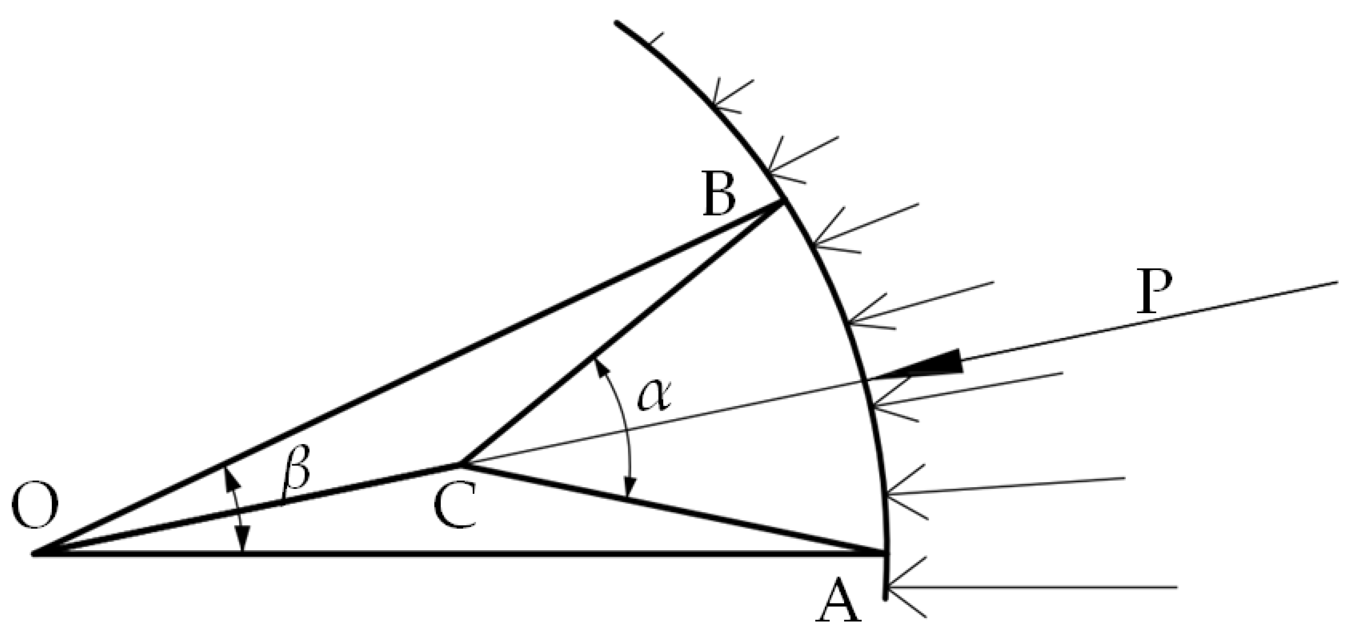
3.1. Geometric Model

A geometric model of an open-top radial gate in a hydropower station was established and used as an example for analysis. The orifice sizes were 13 × 24.3 m2 (length × width), the sill height of the gate was 193.5 m, the hinge height was 217.6 m, the globoidal radius was 32 m, the normal water level was 217.3 m, and the design water head of the radial gate was 23.8 m. According to the principle of equal load arrangement of an open top radial gate, the calculation formula of the main beam position is as follows:
y k = 2 H 3 n [ k 1.5 ( k 1 ) 1.5 ] ,
where yk is the distance from the k main beam to the water surface (m); H is the distance from the water surface to the gate bottom (m); and n is the number of the main beam. A double main beam layout method was adopted, and from the known quantities H = 23.8 and n = 2, the unknown quantities y1 = 11.22 m and y2 = 20.51 m were obtained. The connection positions A and B between the dendritic arm structure with a two-branched structure and the main beam were obtained. The position of crotch point C was an important research point. The layout of seeking the crotch point C of the dendritic arm structure in the longitudinal plane is shown in Figure 1.
In Figure 1, O is the hinge point according to the principle of equal load arrangement, A and B are the connection points between the main beam and arm, respectively, P is the resultant force of the water load, OD is the action line of P, the crotch point C is in OD, the point D is the intersection point of AB and the water load action line, and α and β are the angles (°) of the two branches and two arms, respectively. The geometric relations in Figure 1 were as follows: LOB = LOA = 32 m, BCD and ADC triangles were all right triangles, and LBD = LAD = 4.8 m and LOD = 31.64 m. The trunks and branches adopted a box-section; the trunk was rectangular, while the branch was square (Figure 2 and Figure 3). To facilitate the construction, the section width of the branch was the same as that of the trunk. a1, b1, and t1 are the section width and height and the wall thickness of the trunk, respectively; a1 and t2 are the section width and wall thickness of the branch, respectively, and LOC and LCA represent the length of the trunk and branch, respectively. All units are in m.

3.2. Computational Model

Based on the fundamental concept of structural optimization design, an optimization model for solving the crotch point was developed [17]. Initially, the size optimization of the cross-section was implemented based on the local stability, and the concurrent instability of the trunks and branches was deemed objective. On the basis of the size optimization of the cross-section, the strength, stiffness, and stability of the dendritic arm with a two-branched structure were regarded as the constraint conditions, the highest overall structural stability and the lightest weight were regarded as the objectives, and the structure optimization model of the dendritic arm with a two-branched structure was subsequently developed. The structural finite element method was used to implement the eigenvalue buckling analysis, double nonlinear buckling analysis, and optimization solution of the dendritic arm with a two-branched structure.

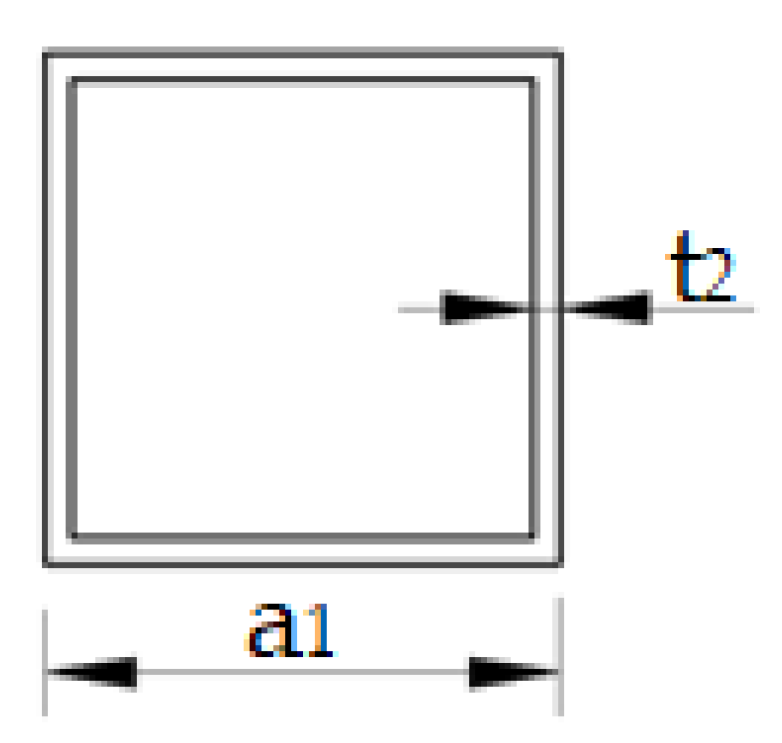
3.2.1. Parameter Selection

The section size and length of the trunk and branch were selected as the optimization variables, namely the section sizes of the trunk, a1, b1, and t1, and the section sizes of the branch, a1 and t2; the lengths of the trunk, l1, and branch, l2, were selected as the design variables. In order to obtain the universal conclusion in the process, the free variables were treated by the non-dimensional analysis method, namely the unit stiffness ratio of the trunk and branch and the angle ratio between the two branches and two arms were given, which were used as the optimal design results.
In order to determine the reasonable crotch point, the enumeration method was adopted. Supposing Loc = x (1.0 ≤ x ≤ 29.5), the step length of x is 0.05 m; upon scanning it, the length of the branch and trunk vary in the range from 5.26~31.01 (m) and 1.0~29.5 (m), respectively. The optimization parameters and design variables are shown in Table 1.

3.2.2. Constraint Conditions

  • Strength: σi ≤ [σ], i = 1,2,3, where σi is the critical stress of the trunk and two branches, respectively, where [σ] = 345 MPa;
  • Stiffness: λmax ≤ [λ], where the maximum flexibility of a strut must be less than the permissible value λmax in the specification and satisfy the flexibility range of a medium flexibility strut. In the specifications of radial gates, the allowable value [λ] of the arm is 120;
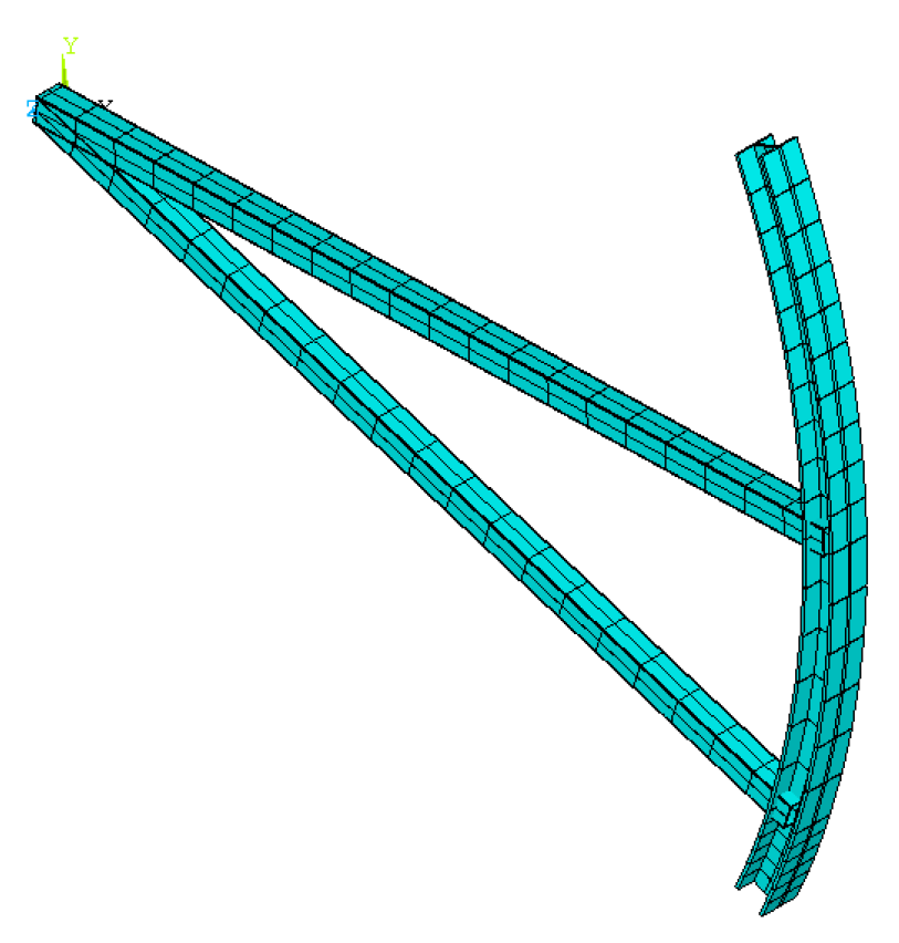
  • Overall stability: a double nonlinear buckling analysis of a dendritic arm with a two-branched structure was implemented using the structural finite element method to ensure the overall stability of the structure;
  • Local stability: the ratio of the width and thickness of a flange must meet Formula (7), that is:
a 2 t t 40 235 σ s ,
where σ s is the yield stress, i.e., 345 MPa, the ratio of a section’s width and thickness meets a/t ≤ 35, and the local stability factor is j = a 2 t t / 40 235 σ s . In order to make full use of the material and improve the calculation efficiency, different local stability factors were selected to optimize the calculation.

3.2.3. Objective Function

When the length of trunk x takes different values, the material weight of the dendritic arm with a two-branched structure can be calculated by Formula (8):
G ( x ) = { [ 2 ( a 1 + b 1 ) t 1 4 t 1 2 ] l 1 x + 2 ( 4 a 1 t 2 4 t 2 2 ) l 2 x } ρ g ,
where ρ is the density of steel (kg/m3) and g is the gravitational acceleration (m/s2). According to the principle of equal weight, the cross-section size of the two-arm structure can be determined. The minimum ratio of the total material weight and overall buckling load of the dendritic arm with a two-branched structure is given by the objective function G / P c r min { G ( x ) / P c r ( x ) } .

3.3. Solution of Numerical Optimization

A set of finite element models were established, and the models of two arms and two branches are shown in Figure 4 and Figure 5.
The effects of the material, geometric double nonlinearity, and initial geometry defects of the component were considered in the calculation and analysis process. The specific analysis procedure was as follows:
  • According to the geometric model, the crotch points were determined; then, the appropriate unit model, Beam188, was chosen. The unit has two nodes and two beam elements and is based on Timoshenko’s beam element theory. The large deformation, large angle, and large strain effect of the beam element were considered in the nonlinear analysis;
  • Material properties were determined: the yield strength of Q345 B steel is 345 MPa, and the elastic modulus and Poisson’s ratio are 2.06 × 10⁵ MPa and 0.3, respectively, which is considered as an ideal elastic–plastic material. The bilinear isotropic hardening model (BISO) was used to simulate its constitutive relations in ANSYS software;
  • Constraints were imposed: according to the design specifications of a steel gate, the line stiffness ratio of main longitudinal beam and branch is controlled within the range of 4~11. The branch and girder are a rigid connection, while the hinge is hinged at the trunk;
  • Initial imperfections were applied: according to the specifications of a steel gate, the initial imperfection of the dendritic arm with a two-branched structure was applied; its standard was 0.1% of the first-order buckling deflection, which was obtained by eigenvalue buckling analysis [18];
  • The NR method was used to solve the problem, and the Von-Mises yield criterion was adopted. Finally, the results of extraction and analysis were carried out.

4. Calculation Analysis

4.1. Comparison of Two Kinds of Arm Structures

The buckling loads of the dendritic arm structure with two branches and two arms were calculated using the eigenvalue buckling analysis method and the double nonlinear finite element method when the crotch points were in different positions. To eliminate the influence of the absolute sizes between the trunk length and cross-section size and between the branch length and cross-section size, the unit stiffness ratio between the trunk and branch and the angle ratio between two branches and two arms were used as non-dimensional parameters. To determine the advantages and disadvantages of the dendritic arm structures with a two-branched structure and a two-armed structure, the change rules of the buckling load ratio and the unit stiffness ratio, as well as those of the material saving rate and the local stability coefficient, are depicted in Figure 6 and Figure 7.
As shown in Figure 6, when the unit stiffness ratio ( i g z ) of the trunk and branch was within the interval (0.99, 5.67) under the same amount of material consumption, the buckling load ratio ( p c r ( s ) / p c r ( e ) ) of the dendritic arm with a two-branched and two-armed structure increased with the increase in the unit stiffness ratio ( i g z ) of the trunk and branch. While the ratio ( p c r ( s ) / p c r ( e ) ) was within the interval (5.67, 171.88), the ratio ( p c r ( s ) / p c r ( e ) ) reduced. It is worth noting that the ratio ( p c r ( s ) / p c r ( e ) ) exceeded 1 when the ratio ( i g z ) was within the interval (0.99, 26.78), which showed that the buckling load of the dendritic arm with a two-branched structure was higher than that of the two-armed structure within this range. Moreover, when the ratio ( i g z ) was 5.67, the ratio ( p c r ( s ) / p c r ( e ) ) reached the maximum; its value was 2.50~4.34. The specific variation range depended on the local stability factor, and the ratio ( p c r ( s ) / p c r ( e ) ) reached the maximum when the local stability factor was 1.
As shown in Figure 7, under the same critical load, there was a positive correlation between the material saving rate ( ν ) of the dendritic arm with a two-branched structure and the local stability factor. When the local stability factor was 1, the maximum value of ν was 52.54%, and the local stability factor was 0.545; the minimum value of ν was 37.19%. Therefore, under the condition of a reasonable structure, the buckling load of the dendritic arm with a two-branched structure was higher than that of the two-armed structure with the same material consumption, which was 4.34 times that of the two-armed structure. The self-weight of the dendritic arm with a two-branched structure was less than that of the two-armed structure, and its material saving rate reached 52.54% with the same critical load. The above fully showed that the reasonable structure of the dendritic arm with two branches had the advantages of high stability and light weight.

4.2. Optimization Results of the Dendritic Arm with Two-Branched Structure

In order to determine the optimal tree type, the relation graphs between the optimal object G ( x ) / P c r ( x ) with the unit stiffness ratio i g z and α / β are shown in Figure 8 and Figure 9, respectively, where G ( x ) / P c r ( x ) is the ratio of the material weight and buckling load of the dendritic arm with a two-branched structure, α is the angle between the two branches of the dendritic arm with a two-branched structure; and β is the angle between the two arms.
As shown in Figure 8, when the unit stiffness ratio ( i g z ) of the trunk and branch was within the interval (0.99, 5.67), the ratio ( G ( x ) / P c r ( x ) ) of the material weight and buckling load of the dendritic arm with a two-branched structure reduced with the increase in the ratio ( i g z ); while the ratio ( i g z ) was within the interval (5.67, 171.88), the ratio ( G ( x ) / P c r ( x ) ) increased with the increase in the ratio ( i g z ). When the cut-off point i g z was within the interval [5.33, 6.02], the objective function reached the minimum. This implied that the tree type was the best one at this time. The objective function ( G ( x ) / P c r ( x ) ) reduced with the increase in the local stability factor of the trunk and branch but changed little; when the local stability factor was 1, the objective function reached the minimum.
As shown in Figure 9, when the angle ratio ( α / β ) was within the interval (1.03, 1.98), the ratio ( G ( x ) / P c r ( x ) ) of the material weight and buckling load of the dendritic arm with a two-branched structure reduced with the increase in the ratio ( α / β ); while the ratio ( α / β ) was within the interval (1.98, 7.65), the ratio ( G ( x ) / P c r ( x ) ) increased with the increase in the ratio ( α / β ). When the cut-off point α / β was within the interval [1.92, 2.04], the objective function reached the minimum. This implied that the tree type was the best one at this time. The objective function reduced with the increase in the local stability factor of the trunk and branch but changed little; when the local stability factor was 1, the objective function reached the minimum.
In conclusion, the parameter settings of the optimal tree type were as follows: the unit rigidity ratio between the trunk and branch was [5.33, 6.02], and the angle ratio between the two branches and two arms was [1.92, 2.04]. Moreover, the corresponding length ratio of the tree type between the branch and trunk was 1.02, the section height ratio of the trunk and branch was 1.805, and the flange thickness ratio of the trunk and branch was 1.405. At this time, the overall stability of the dendritic arm with a two-branched structure was the highest, and its weight was the lightest.

5. Influence of Radial Gate Radius on the Optimal Tree Type of Dendritic Arm with Two Branches

The above analysis was only a conclusion under the conditions that the radial gate radius was determined; in fact, the code for the design of steel gates in water conservancy and hydropower projects stipulates that the ratio between the curvature radius and the gate height for an open-top radial gate panel is 1.0~1.5, so it is necessary to further investigate the effects of different radial gate radii on the optimal tree type. The radius of this project was 24.3~36.5 (m). The above analysis only chose 32 m, so the same thought was adopted to study the effects of the unit stiffness ratio between trunks and branches and the angle ratio between two branches and two arms on the optimal tree type of the dendritic arm with two branches by selecting two set radii of 28 m and 36 m.
The analysis results of the three different radii are plotted in the same graph below; the objective function was regarded as the longitudinal axis, and the unit stiffness ratio between the trunk and branch was considered as the horizontal axis, as shown in Figure 10.
It is known from Figure 10 that the corresponding unit stiffness ratios between the trunk and branch were [5.33, 6.11], [5.33, 6.02], and [5.34, 5.95] when the radius was 28 m, 32 m, and 36 m, respectively. Moreover, the objective function obtained the minimum value. In the same way, the angle ratios between the branch and two arms were [1.91, 2.04], [1.92, 2.04], and [1.93, 2.04], respectively. The specific calculation results are shown in Table 2
  • where l z g is the length ratio of the branch and trunk, h g z is the height ratio of the cross-section of the trunk and branch, and t g z is the thickness ratio of the cross-section of the trunk and branch. From Table 2, l z g , h g z and t g z were almost constant with the increase in the radius, while the change in i g z and α / β were very small. From Figure 10 and Table 2, the radial gate radius had little effect on the optimal tree type and mechanical properties of the dendritic arm with two branches.

6. Conclusions

A double nonlinear buckling analysis regarding the geometry and material and a numerical optimization of a tree-type dendritic arm with a two-branched structure were implemented by structural finite element method. As a result, the following conclusions were drawn:
  • A new type of Y-armed structure obtained the respective advantages of high stability with fewer arms and large stiffness with more arms, overcoming the corresponding disadvantages, and the twin objectives of high stability and light weight when the tree type was reasonable could be embodied. Therefore, the new type of Y-armed structure of a radial gate was better than that of the traditional V-type arm structure.
  • The parameter settings of the optimal tree type were as follows: the angle ratio between the branches and two arms was [1.92, 2.04], the unit rigidity ratio between the tree trunk and branch was [5.33, 6.02], the length ratio between the corresponding branch and trunk was [0.96, 1.09], the height ratio of the section between trunk and branch was 1.805, and the flange thickness ratio was 1.405. Then, the trunk and branches were unstable simultaneously, the utilization rate of the material reached the maximum, the structure was the lightest, and the overall structural stability was the highest.
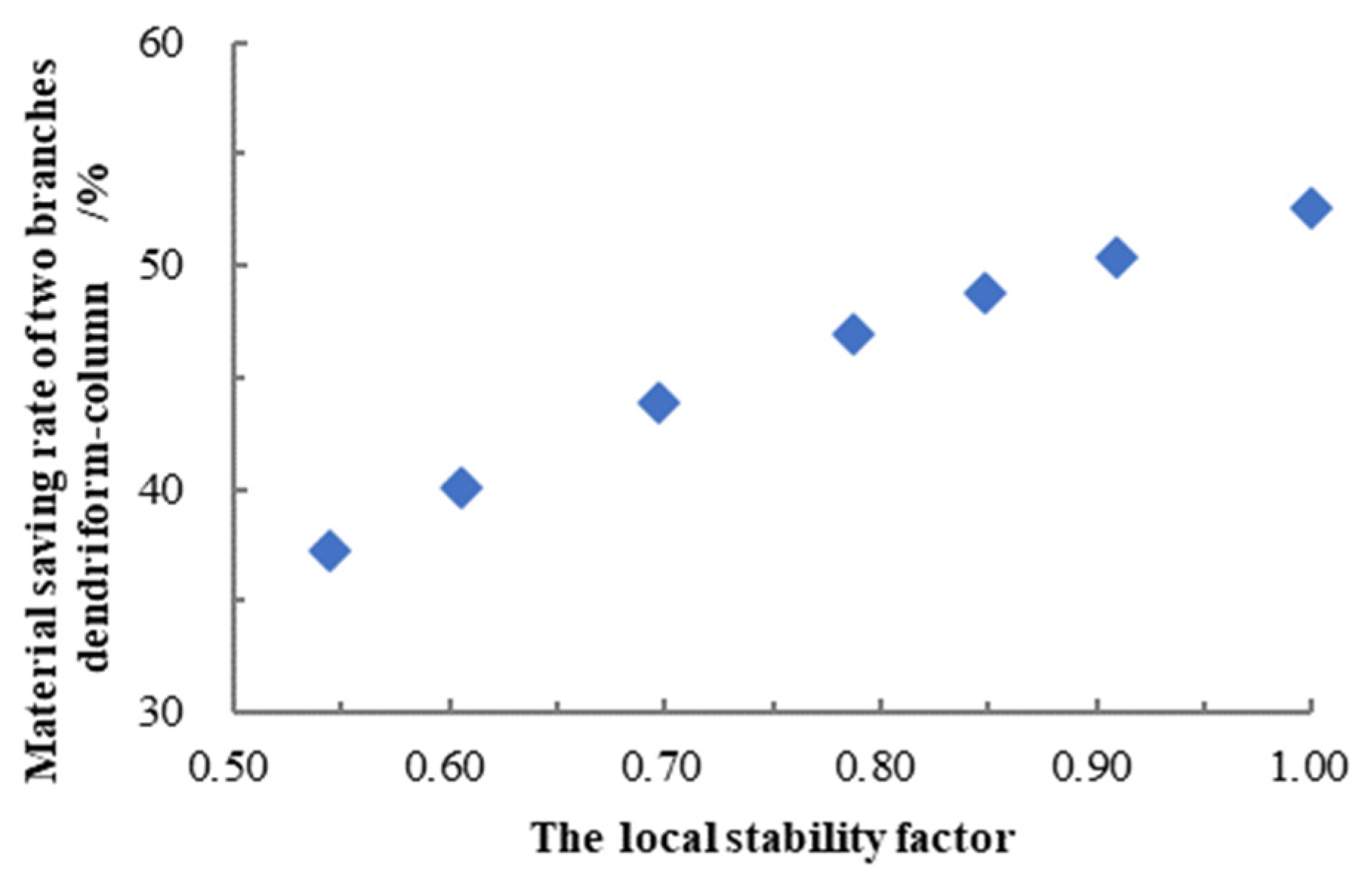
  • Compared with two arms when the tree type was optimal, the overall stability of the Y-type structure was higher under the same material, and its overall buckling load was 2.50~4.34 times that of V-type structure; otherwise, the weight of the Y type structure was light under the same critical load, and its material saving rate was 37.19~52.54%. The specific range depended on the local stability coefficient, and when the local stability coefficient was 1, the material saving rate achieved the maximum value.
This paper investigated the stability in the plane of a Y-type structure under a static load. Due to space constraints, further research on optimizing the tree type under a dynamic action, taking a hoisting load into account, will be presented in a separate paper.

Author Contributions

Conceptualization, Y.H., X.Z. and Z.W.; methodology, X.Z., K.C. and Z.W.; software, X.Z. and J.L.; validation, Y.H., X.Z. and X.C.; formal analysis, X.C.; investigation, Y.H. and K.C.; resources, Y.H., X.C. and K.C.; data curation, X.Z. and X.C.; writing—original draft preparation, Y.H. and X.Z.; writing—review and editing, Y.H., Z.W. and K.C.; visualization, Y.H. and J.L.; supervision, Z.W.; project administration, Y.H., K.C. and X.C.; funding acquisition, Y.H., K.C. and X.C. All authors have read and agreed to the published version of the manuscript.

Funding

This research received no external funding.

Institutional Review Board Statement

Not applicable.

Informed Consent Statement

Not applicable.

Data Availability Statement

Not applicable.

Acknowledgments

The author would like to gratefully acknowledge the support of NSFC and the teacher, Li Baohui, for his help in analyzing the results.

Conflicts of Interest

The authors declare no conflict of interest.

References

  1. Zhang, J.; Liu, G. Accident analysis and research on light radial steel gate. J. Hydroelectr. Power Gener. 1992, 11, 49–57. (In Chinese) [Google Scholar]
  2. Iasef, M.; Mario, S. Tree-inspired dendriforms and fractal-like branching structures in architecture: A brief historical overview. Front. Archit. Res. 2014, 3, 298–323. [Google Scholar]
  3. Zhang, J. Morphological Analysis and Engineering Applications of Branching Structures. Master’s Thesis, Harbin Institute of Technology, Harbin, China, 2011. [Google Scholar]
  4. Von Buelow, P. A Geometric Comparison of Branching Structures in Tension and Compression versus Minimal Paths. In Proceedings of the IASS 2007 Symposium, Venice, Italy, 3–6 December 2007. [Google Scholar]
  5. Falk, A.; Von Buelow, P. Evolution and Trends in Design, Analysis and Construction of Shell and Spatial Structures. In Proceedings of the International Association for Shell and Spatial Structures (IASS) Symposium 2009, Valencia, Spain, 28 September–2 October 2009. [Google Scholar]
  6. Allen, E.; Zalewski, W. Formand Forces: Designing Efficient, Expressive Structures; John Wiley & Sons: New York, NY, USA, 2009. [Google Scholar]
  7. Hunt, J.; Haase, W.; Sobek, W. A Design Tool for Spatialtree Structures. J. Int. Assoc. Shell Spat. Struct. 2009, 50, 3–10. [Google Scholar]
  8. Kurz, E.; Rau, L.; Frühauf, N.; Haase, W.; Prskalo, M.; Sobek, W. Cost-Efficient manufacturing process of switchable glazing based on twisted nematic LC cells. Proc. SPIE-Int. Soc. Opt. Eng. 2011, 8114, 892753. [Google Scholar]
  9. Luo, Y. Finite element analysis of dendriform-column. Steel Constr. 2005, 20, 46–49. (In Chinese) [Google Scholar]
  10. Ma, H.; Shen, L.; Gao, B. Stability design on the dendritic structure with steel tubes. Build. Struct. 2009, 39, 97–99. (In Chinese) [Google Scholar]
  11. Zhang, J.; Chen, S.; Lin, J. Morphological analysis of steel pipe dendritic supporting structure. Eng. J. Wuhan Univ. 2009, 42, 240–243. (In Chinese) [Google Scholar]
  12. Wang, Z.; Chen, J.; Zhang, Q. Research on design of dendritic columns in Bionic Steel Structures. Struct. Eng. 2010, 26, 21–25. (In Chinese) [Google Scholar]
  13. Wu, Y.; Zhang, J.; Cao, Z. Form-finding analysis and engineering application of branching structures. J. Archit. Struct. 2011, 32, 162–168. (In Chinese) [Google Scholar]
  14. Ministry of Water Resources of the People’s Republic of China. Specification for Design of Steel Gate in Hydraulic and Hydroelectric Engineering (SL74-2013); Water & Power Press: Beijing, China, 2013.
  15. Zhu, J.; Wang, Z.; Fang, H. Application of topology optimization in optimal layout of large radial steel gate. Yellow River 2007, 29, 63–64. (In Chinese) [Google Scholar]
  16. Memon, B.; Su, X.Z. Arc-length technique for nonlinear finite element analysis. J. Zhejiang Univ. Sci. 2004, 48, 121–131. [Google Scholar] [CrossRef] [PubMed]
  17. Wang, G.; Dong, M. Structural Optimization Design; Higher Education Press: Beijing, China, 1987. (In Chinese) [Google Scholar]
  18. Shi, G.; Lin, C.; Zhou, W.; Wang, Y. Finite element analysis and design method study on the local buckling of 460 mpa hss box section axial compressed columns. Eng. Mech. 2014, 31, 128–136. (In Chinese) [Google Scholar]
Figure 1. Layout of the dendritic arm of the radial gate with two branches.
Sustainability 14 16507 g001
Figure 2. Cross-section of the trunk.
Sustainability 14 16507 g002
Figure 3. Cross-section of branch.
Sustainability 14 16507 g003
Figure 4. Finite element model of two arms.
Sustainability 14 16507 g004
Figure 5. Finite element model of two branches.
Sustainability 14 16507 g005
Figure 6. Relation graph of i g z and p c r ( s ) / p c r ( e ) . Note: tg is the ratio of width and thickness of the trunk, tz is the ratio of width and thickness of the branch, i g z is the unit stiffness ratio of trunk and branch, p c r ( s ) is the buckling load of the dendritic arm with two-branched structure (KN), and p c r ( e ) is the buckling load of that with a two-armed structure.
Sustainability 14 16507 g006
Figure 7. Relation graph of j z and ν . Note: j z is the local stability factor, ν is the material saving rate of dendritic arm with two branches under the same buckling load ν = ( m e m s ) / m e × 100 % , m e is the material consumption of the two-armed structure (Kg), and m e is the material consumption of the dendritic arm with two branches (Kg).
Sustainability 14 16507 g007
Figure 8. Relation graph of G ( x ) / P c r ( x ) and i g z .
Sustainability 14 16507 g008
Figure 9. Relation graph of and G ( x ) / P c r ( x ) and α / β .
Sustainability 14 16507 g009
Figure 10. Relation graph of G ( x ) / P c r ( x ) and i g z under the different radii.
Sustainability 14 16507 g010
Table 1. Optimization parameters and variables.
Trunk Length/mBranch Length/mLength Ratio of Branch and TrunkUnit Stiffness Ratio of Trunk and BranchAngle Ratio between Two Branches and Two Arms
1.0031.0131.01171.881.03
1.5030.5220.35112.761.05
29.005.480.191.057.09
29.505.260.180.997.65
Table 2. Calculation results.
R(m)283236
i g z [5.33, 6,11][5.33, 6.02][5.34, 5.95]
α / β [1.91, 2.04][1.92, 2.04][1.93, 2.04]
l z g [0.96, 1.10][0.96, 1.09][0.96, 1.07]
h g z 1.8051.8051.805
t g z 1.4051.4051.405
Publisher’s Note: MDPI stays neutral with regard to jurisdictional claims in published maps and institutional affiliations.

