Abstract
Vacuum tube well dewatering technology has gradually become an effective means to deal with low-permeability soil groundwater. The vacuum degree transfer law is an important element in the study of the mechanism of deep foundation pit vacuum tube well dewatering. To further study the transfer law of vacuum degree in vacuum tube well dewatering, a laboratory test setup for vacuum tube well dewatering was developed, and vacuum tube well dewatering tests were conducted under various in-well vacuum values, tube diameter, depth of tube well, and other factors. The variation law of vacuum degree under various working condition coupling was thoroughly analyzed in this research. The results show that with the increase of vacuum value in the well, the radial vacuum degree and vertical vacuum degree have about 14.9~47.7% and 14.9~32.4% increase, respectively, and transmission attenuation of radial vacuum degree, transmission attenuation of vertical vacuum degree, and the range of the vacuum field all increase to some extent. With the outward transmission of the vacuum degree, the transmission attenuation of the radial vacuum degree decreases rapidly and then tends to be stable, and the transmission attenuation of the vertical vacuum degree decreases gradually. The radial vacuum degree, the transmission attenuation of the radial vacuum degree, and the range of the radial vacuum field are not affected by the buried depth of the tube well. The study’s conclusions can serve as a foundation and point of reference for projects involving the design and implementation of deep foundation pit vacuum tube well dewatering.
1. Introduction
In recent years, more and more deep foundation pit projects are in the process of being built in China as urban rail transit and subterranean space increase quickly [1,2,3,4]. Groundwater disasters frequently occur in the process of deep foundation pit dewatering, such as quicksand, piping, inrush, ground subsidence, and other adverse geological disasters [5,6]. At the same time, difficulties such as the small amount of water, long periods, and low efficiency of dewatering in the process of deep foundation pit dewatering are becoming more and more prominent [7,8]. Therefore, some researchers have applied vacuum technology to foundation pit dewatering engineering and put forward vacuum tube well dewatering technology [9]. Compared with conventional tube well dewatering, the water yield under vacuum tube well dewatering can be increased by more than 10 times. Vacuum tube well dewatering technology has also achieved a good dewatering effect in low permeability strata. Although vacuum tube well dewatering technology has been widely used in deep foundation pits in low-permeability soil layers, theoretical study on vacuum tube well dewatering is still in its early stages [10]. The distribution of vacuum degree in the soil directly affects the effect of vacuum tube well dewatering, which is an important content of vacuum tube well dewatering mechanism research in deep foundation pits. Therefore, it is of great engineering significance to study the transfer law of vacuum degree in vacuum tube well dewatering and improve the dewatering efficiency.
At present, many research scholars have carried out a series of studies on the law of vacuum degree transmission in the soil body. Zhang [11] derived the theoretical relationship equation between vacuum degree and pore water pressure difference based on the gas state equation and equilibrium equation. Stewart [12] proposed an analytical model for stable, axisymmetric gas flow in a single-well inhomogeneous (laminar) soil and derived expressions for vacuum, velocity, and flow lines using the generalized integral transformation method. Huang [13,14,15] found four stages of vacuum degree transmission with distance, such as high vacuum section, rapid decay section, relatively smooth section and vacuum extinction section, through laboratory tests on unsaturated sandy soil. He derived the distribution law of vacuum pressure in the soil using Darcy’s law and the steady-state seepage control equation based on the particle and pore model. Jia [16] divided the area around the vacuum tube well into the vacuum and gravity field coupling zone, coupling field and gravity field transition zone, and gravity field zone by establishing a submerged 3D groundwater flow model, and the vacuum degree in the well affects all three zone ranges. Vu [17] found that the distribution of vacuum degree along the tube well was different from that of PVD (prefabricated vertical drain) at the axisymmetric single vacuum well point. The vacuum degree in the well increased linearly with depth and was constant at the bottom. Zhuo [18] studied the temporal and spatial variation of vacuum degree in soil by laboratory tests and proposed a vacuum transfer model considering the variation of attenuation coefficient inside and outside the congested zone. Zhu [19] found that different medium resistance has a great influence on vacuum degree, and the transmission of vacuum degree was blocked by the groundwater level. Geng [20] analyzed the distribution law of vacuum degree under sealed and unsealed membranes by analytical method. According to field studies, Bao [21] discovered that the soil’s self-weight deposition law had some bearing on the properties of soil’s negative pressure transfer at various depths, and negative pressure attenuation was negatively correlated with coarse particle content at depth. Through the field test of vacuum tube well dewatering, Zeng [22] and Li [23] found that the consolidation effect of vacuum tube well dewatering technology is remarkable, and they described the change law of vacuum degree in the soil layer. The majority of researchers agree that there is an attenuation of the vertical transmission of vacuum degree in the soil, but the shape of the attenuation is characterized variably. Jiang [24] analyzed the distribution law of negative pressure through a 15 m large-scale laboratory model test. He discovered that there is a clear hysteresis effect when measuring the vacuum degree in saturated clay, and the vacuum degree in the soil at key time points was linearly distributed along the depth. Based on a one-dimensional semi-permeable boundary foundation model, Hu [25,26] discovered that the ultimate negative pressure down the depth displayed a single linear attenuation, piecewise linear attenuation, and curve attenuation when the permeability coefficient of the soil layer was equal, uneven, and continuous. Khan [27] found that the transfer rate of vacuum degree in the soil is different at different depths. However, after soil consolidation under ideal assumptions, the vacuum degree was constant with depth.
The studies mentioned above primarily concentrate on the attenuation law of vacuum degrees in soil and the transfer law of vacuum degrees with distance, depth, and time. However, there are few publications on the influencing factors of vacuum transfer under vacuum tube well dewatering. For this purpose, the article has performed vacuum tube well dewatering model experiments under various circumstances, including varying vacuum values, pipe diameters, and buried depths. Through repeated tests, a butyl rubber that can effectively solve the problem of sealing in the model test was found. The article analyzed the influence mechanism of various factors on vacuum degree transmission law. This article is expected to give direction for vacuum tube well dewatering construction in actual engineering.
2. Development of Vacuum Tube Well Dewatering Laboratory Model and Scheme Design
2.1. Development of Model Test Device
Laboratory model test with a deep foundation pit precipitation in a station of Zhengzhou subway as the research background. The groundwater in the foundation pit is phreatic water, and the phreatic water layer exists in the silty sand and clay silty soil layer. The transfer law of vacuum degree is primarily studied in this research under different affecting conditions. To study the above issues in a targeted manner, some working circumstances have been relatively simplified, and the geometric similarity ratio is 1:25.
The model test device is mainly composed of six parts: model box, dewatering tube well, water pumping system, air pumping system, measuring system, and sealing system. The test device is shown in Figure 1, Figure 2, Figure 3 and Figure 4. The test apparatus is described in Table 1.
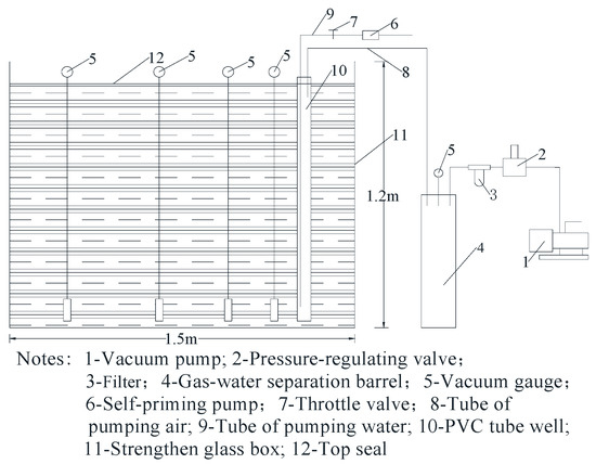
Figure 1.
Schematic diagram of vacuum tube well dewatering laboratory test device.
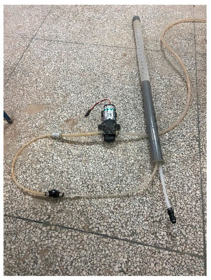
Figure 2.
Physical drawing of the water pumping system.
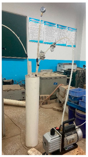
Figure 3.
Physical drawing of the air pumping system.
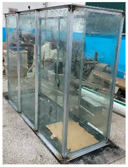
Figure 4.
Model box physical drawing.

Table 1.
Description of the experimental model system.
The test model is a cuboid structure bonded with 15 mm thick toughened glass, whose length is 1.5 m, width is 0.5 m, and height is 1.2 m. Triangle steel is welded to the test device to hold back the soil sample’s radial distortion, to ensure that the test box will not produce large deformation under the combined force of water and soil, and to prevent the test chamber from producing water leakage and air leakage. The model box entity is shown in Figure 4.
The dewatering tube well is made of PVC pipe. By drilling holes in the PVC pipe to simulate the permeable section of the tube well and drilling in strict accordance with the porosity of the permeable section of the actual dewatering well. The permeable section is wound with 100 mesh nylon mesh to prevent soil particles from entering the tube well. The length of the permeable section varies with the length of the tube well. The wellhead is sealed with professional glue and a transparent PC plate, and the water pumping hole and the bleeder hole are reserved on the PC plate. The tube diameter and length are set to 40 mm, 50 mm, 63 mm and 0.7 m, 0.9 m, 1.1 m, respectively.
During engineering, the vacuum degree in the soil is usually measured by a spring tube vacuum gauge. In the process of vacuum pumping, the fluid state of the measuring point in the soil changes. When the fluid pressure is less than the standard atmospheric pressure, a pressure difference will be generated inside and outside the vacuum degree probe. The air in the cavity of the thin tube and measuring tube is sucked away, and then the vacuum gauge generates a reading. That is the vacuum degree of the measuring point [24]. This paper uses a vacuum gauge with a range of −0.1 to 0 MPa. The physical and structural drawings of the vacuum degree measuring tube are shown in Figure 5 and Figure 6. See Table 1 for details.
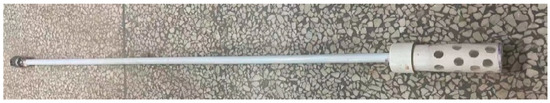
Figure 5.
Vacuum degree measuring tube physical drawing.
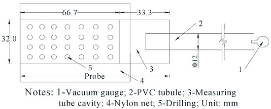
Figure 6.
Vacuum degree measuring tube structure diagram.
The quality of sealing control directly affects the vacuum degree in the soil, thus affecting the test results. To effectively handle the problem of sealing between the contact of diverse materials, after repeated testing to discover a strong adhesion, strong application, and good sealing butyl adhesive. The plastic cloth and the measuring tube (plastic cloth and tube well) are first wound with butyl rubber mud and then wound with rubber cloth. In addition, the sealing of the surface of the soil sample is first covered with plastic cloth, then clay powder (compaction thickness of 1 cm), and finally, plastic cloth and butyl adhesive bonding.
Compared with the existing vacuum tube well dewatering-related indoor model test, the test has the following improvements: ① compared with sandbag +adhesive tape and bentonite slurry sealing method, the found butyl adhesive has a better sealing effect. The vacuum degree is easier to form. ② properly increasing the length of the opening section of the vacuum degree test probe can effectively avoid the occurrence of the phenomenon of no reading of the vacuum gauge. ③ the self-made steam separator effectively solves the problem that the water in the tube well enters the vacuum pump due to excessive suction.
2.2. Test Scheme
2.2.1. Test Soil Sample
The soil samples in this paper were taken from the clayey silt layer within the foundation pit of a station of the Zhengzhou subway, and its relevant physical and mechanical parameters are shown in Table 2. The on-site soil samples were transported back to the laboratory for air-drying, grinding into powder form, and screening. The soil samples were laid in uniform layers from bottom to top and compacted to about 1.1 m, strictly guaranteeing the quality of each layer of filling soil. In addition, in the process of soil sample laying, holes were pre-set for buried dewatering tubes and measurement tubes. Then, water was added to the soil sample according to 22% moisture content, and the moisture content of the soil samples was determined by the drying method. By continuously adjusting the amount of water added to ensure that the moisture content of the test soil sample is essentially consistent with the on-site measured value in the field, the experiment was started after the soil sample stood for a month.
Table 2.
Physical and mechanical parameters of the soil layer.
2.2.2. Test Scheme Design
In this paper, the transmission law of vacuum degree in horizontal and vertical directions under different tube diameters, different vacuum values, and different buried depths is simulated by a single-well vacuum tube well dewatering test with a total of 36 sets of trials. The specific test scheme of single-well vacuum tube well dewatering is shown in Table 3 and Table 4. This test arranged a pumping well and four vacuum degree observation points, and its specific plan layout is shown in Figure 7. The filter section of the tube well and around the vacuum degree probe were backfilled with filter media. The remaining part was sealed with clay. The specific steps of this test are: ① Lay test soil sample in the model box. The moisture content of the soil sample remained at 22%. Embed the tube well and moisturize the tube; ② Close the pumping valve. Open the vacuum pump. Vacuum degree in the tube well reaches the set value by regulating valve (Since the suction force of the vacuum pump is much greater than that of the self-priming pump, pumping and pumping air cannot be carried out at the same time); ③ When the value on the vacuum meter is stable, start recording the data, and the average value is repeated three times.
Table 3.
Single-well vacuum tube well dewatering test scheme in the horizontal direction.
Table 4.
Single-well vacuum tube well dewatering test scheme in the vertical direction.
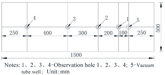
Figure 7.
Layout plan of single-well vacuum tube well dewatering test.
3. Experiment Results and Analysis
Different in-well vacuum values, tube diameters, and depth of embedment will have different degrees of influence on the vacuum source, thus affecting the variation law of the vacuum degree. Therefore, the variation law of vacuum degree in horizontal and vertical directions is studied by establishing various in-well vacuum values, tube diameters, and depth of embedment.
3.1. Effect of Vacuum Value in the Tube Well on the Vacuum Degree Distribution
In order to study the effect of different in-well vacuum values on the vacuum distribution, a single-well vacuum tube well precipitation test was performed by setting three different vacuum value gradients of 40 kPa, 60 kPa, and 80 kPa. The depth of the tube well was set at 1.1 m to reduce the effect of the depth of the tube well. To avoid the contingency of the test and supplement multiple test groups, such as pipe diameter 50 mm, 63 mm test group.
3.1.1. The Distribution of Vacuum Degree in the Horizontal Direction
Based on the data measured in the four vacuum observation holes, the process of the variation of vacuum degree in the horizontal direction under different values of in-well vacuum and different distances (distance from the tube well) is obtained. As shown in Figure 8. As can be seen from Figure 8, the radial vacuum at each point decreases by 41.7%, 30.6%, 20.6%, and 22.3%, respectively (Calculated from Figure 8a) as the distance increases to 100 cm (vacuum value 60 kPa). It can be seen that the radial vacuum presents a tendency to decrease with increasing distance, but the magnitude of the decrease is different at different positions. The process of radial vacuum degree reduction mainly includes two processes: rapid reduction and stable reduction. That is, the radial vacuum degree decreases rapidly in the range of 0~30 cm (41.7%, 30.6%), and the decrease of radial vacuum degree gradually becomes slower in the range of 30~100 cm (20.6%, 22.3%). The three working conditions of 40 kPa, 60 kPa, and 80 kPa are in line with the above trend. This indicates that there is a certain range of vacuum fields [16].
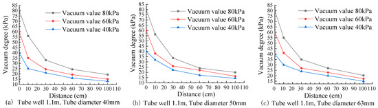
Figure 8.
Variation curve of radial vacuum degree with the value of vacuum in the well.
According to the variation curve of radial vacuum with the value of vacuum in the well in Figure 8, it can be seen that when the vacuum value in the well increases from 40kPa to 60kPa, the radial vacuum degree at each point has an average increase of 30.8%, 15.3%, 20.8%, and 14.9%, respectively. When the vacuum value in the well increases from 60kPa to 80kPa, the radial vacuum degree at each point has an average increase of 47.4%, 31.7%, 17.5%, and 22.9%. This indicates that increasing the in-well vacuum values (40kPa, 60kPa, and 80kPa) can significantly increase the radial vacuum degree at various points within the vacuum field. At the same time as the radial vacuum increases, the increased amplitude is different under different in-well vacuum values. The increasing effect in the range of 60~80kPa is significantly better than that of 40~60kPa. On the other hand, when the vacuum value in the well is increased by 20kPa in turn, the vacuum degree at 100cm has an increase of about 14.9% (Compared to 40kPa) and 22.9% (Compared to 60kPa) respectively. It can be shown that there is a certain degree of increase in radial vacuum degree further away from the tube well, i.e. the range of the radial vacuum field will increase.
As can be seen from Figure 9, the attenuation of the radial vacuum degree transmission attenuation and stabilizes with the vacuum degree transmission to the distant radial direction. The transmission attenuation of the radial vacuum degree near the tube well is larger. The main reason is that when the radial vacuum degree is transmitted from the tube well to the soil, there is a big difference between the two media environments (The obstacles in the soil are greater, which is not conducive to the transmission of vacuum degree). In addition, the pore water flows quickly gather around the tube well (pooling area) under the action of the vacuum seepage field, resulting in an increase in the area occupied by pore water in the seepage channel. Radial vacuum degree overcomes the increase of pore water convection resistance. The radial vacuum degree transmission attenuation is larger [28]. The decay value of the radial vacuum transmissions gradually stabilizes as the distance increases. This is because after the radial vacuum degree crosses the pore water pooling area, the seepage channel has formed and reached stability. The pore water convection resistance gradually stabilized. When the vacuum value in the well increases by 20 kPa in turn, the transmission attenuation of radial vacuum degree increases to some extent, i.e., the attenuation values at different in-well vacuum values are 0.27~1.5 kPa/cm, 0.45~2.5 kPa/cm, 0.61~2.4 kPa/cm, respectively (Calculated from the Figure 9a). It can be seen that the change of the vacuum source caused by the change of the vacuum value in the well affects not only the extent of the vacuum field but also the efficiency of the radial vacuum degree transfer.
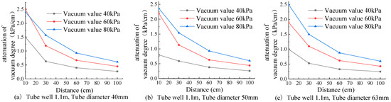
Figure 9.
Variation curve of transmission attenuation of radial vacuum degree with vacuum value in well.
3.1.2. The Distribution of Vacuum Degree in the Vertical Direction
According to the data measured at 70 cm, 90 cm, and 110 cm depths of the No. 2 observation hole, the variation curve of vacuum degree in a vertical direction under different vacuum values is obtained, as shown in Figure 10. It can be observed that the vacuum degree at observation hole No. 2 decreases with the increase of depth, and the vertical vacuum degree is approximately linearly distributed. It has mean slope values of −0.13 kPa/cm, −0.21 kPa/cm, and −0.25 kPa/cm, respectively. This is similar to the results obtained by Jiang et al. in the vertical large laboratory model.
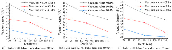
Figure 10.
Variation curve of vertical vacuum degree with vacuum value in the well.
As can be seen from Figure 10, the vertical vacuum degree shows a positive correlation with the value of vacuum in the well as the value of vacuum in the well increases (40 kPa, 60 kPa, 80 kPa). At the same time, the growth of the vacuum degree gradually becomes slower as the depth increases. It can be shown that the greater the depth, the more unfavorable the transmission of vertical vacuum. For example, the average increasing margin of vacuum at each measurement point is 24.8%, 32.4%, and 14.9% when the vacuum value in the well increases from 40 kPa to 60 kPa. The average increasing margin of vacuum at each measurement point is 28.3%, 17.5%, and 24.3% when the vacuum value in the well increases from 40 kPa to 60 kPa. On the other hand, as the vacuum value in the well increased sequentially from 40 kPa to 80 kPa, the vacuum degree at a depth of 110 cm increased by about 14.9% and 14.3% on average, respectively. It can be shown that there is a certain degree of increase in radial vacuum degree further away from the tube well, i.e., the range of the vertical vacuum field will increase.
The diagram line in Figure 11 at a vacuum value of 60 kPa is opposite to the other two diagram lines. This may be due to the vacuum tube at 90 cm being buried improperly or caused by end blockage. With the increase of depth, the transmission attenuation of vertical vacuum degree decreases gradually, but the variation of this transmission attenuation is small. For example, when the depth increases from 90 cm to 110 cm, the transmission attenuation value of vertical vacuum degree is 0.04 kPa/cm, 0.08 kPa/cm, and 0.08 kPa/cm, respectively. As the vacuum value increases from 40 kPa to 80 kPa successively, the average attenuation of vertical vacuum degree is 0.13~0.17 kPa/cm, 0.13~0.21 kPa/cm, and 0.25~0.33 kPa/cm, respectively. It can be seen that when the vacuum value in the well increases, the transmission attenuation of the vertical vacuum also increases. The change of in-well vacuum value also has a certain extent of influence on the transmission attenuation of vertical vacuum, but how it affects the transmission attenuation of vacuum degree needs to continue the related research.
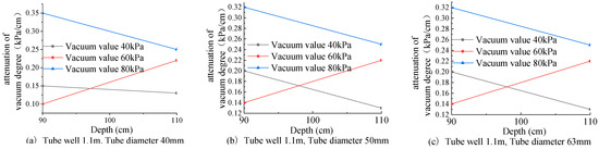
Figure 11.
Variation curve of transmission attenuation of vertical vacuum degree with vacuum value in well.
The essence of vacuum degree transfer is the movement of gas molecules from the high-density region to the low-density region, and the movement of gas molecules needs to overcome the resistance to perform work, and then there will be energy loss [29]. When vacuum pumping is performed, the pore water in the vacuum seepage field gradually moves to the tube well along the vacuum seepage channel between porous media [30,31]. The radial vacuum degree is transmitted to the distance, and convection occurs with pore water. The vertical vacuum degree is hindered by pore water convection and the self-weight sedimentation of the soil. This leads to a gradual increase in radial and vertical vacuum transfer losses, so there is a decrease in a vacuum degree with increasing distance and depth. When increasing the vacuum in the well, the residual energy of the vacuum degree to overcome the same path resistance increases; therefore, there is an increase in the vacuum at the same location. At the same time, the transmission path of the radial vacuum increases gradually, and the range of the vacuum field increases accordingly.
3.2. The Influence of Tube Well Diameter on Vacuum Degree Transmission
3.2.1. The Distribution of Vacuum Degree in the Horizontal Direction
To study the influence of tube diameter on the change of vacuum degree in the horizontal direction, three kinds of tube diameters of 40 mm, 50 mm, and 63 mm are used for the vacuum tube well dewatering test. The vacuum value in the well was set to 60 kPa to reduce the effect of the vacuum value in the well; at the same time, two test groups of tube well depths of 0.7 m and 0.9 m were conducted. The test results are shown in Figure 12.
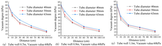
Figure 12.
Variation curve of radial vacuum degree with tube well diameter.
According to the variation curve of radial vacuum degree with the vacuum value in the well in Figure 12, it can be seen the average increasing margin of vacuum at each measurement point is 6.9%, 5.4%, 9.0%, and 6.0% when the vacuum value in the well increases from 40 mm to 50 mm. The average increasing margin of vacuum at each measurement point is 9.2%, 11.9%, 5.9%, and 8.0% when the vacuum value in the well increases from 50 mm to 63 mm. It can be observed that the increase of the tube diameter increases the radial vacuum degree at the points in the vacuum field, but the effect of this improvement is not good (compared to changing the vacuum value in the well). This is mainly because the increase of the tube diameter is equivalent to the expansion of the vacuum source to the outside, the vacuum degree measurement tube buried position remains unchanged, and thus it can be considered that the distance between the buried position of the measurement tube and the wall of the tube well is reduced. The radial vacuum increases with the decrease in the distance, so there is a certain degree of increase in the vacuum when the tube diameter increases. Due to the limited increase of tube diameter, the improvement of radial vacuum degree is not good. Additionally, the increase of radial vacuum degree at each point shows a decreasing trend, and the increased margin of radial vacuum degree is small. This indicates that the farther radial vacuum does not change greatly with the increase in distance, i.e., the range of the radial vacuum field is essentially constant. The main reason for this is that the path of radial vacuum degree transfer remains the same when only the diameter of the pipe is changed, given that both the vacuum in the well and the nature of the soil layer remain unchanged. It can be considered that the range of vacuum field expansion is equivalent to an increased tube diameter. The increased tube diameter is much smaller than the range of the vacuum field; therefore, the range of the vacuum field can be considered to be constant.
It can be seen from Figure 13 that when the tube diameter increases in turn, the transmission attenuation of the radial vacuum degree decreases first and then remains unchanged. When in the range of 0~30 cm, the transmission attenuation of the radial vacuum exists significantly decreases with the increase of the tube diameter (compared to the range of 30~100 cm). The main reason is that with the increase in tube diameter, the distance between the measuring tube and the tube wall decreases, and the transmission path of radial vacuum degree in the seepage channel decreases. With other conditions unchanged, the transmission attenuation of radial vacuum degree will decrease. On the other hand, as the distance continues to increase, the transmission attenuation of the radial vacuum degree is essentially unchanged. It can be found that the change of the vacuum source caused by the change of the tube diameter does not affect the extent of the radial vacuum field and the transmission attenuation at a farther distance.
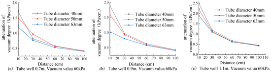
Figure 13.
Variation curve of transmission attenuation of radial vacuum degree with tube well diameter.
3.2.2. The Distribution of Vacuum Degree in the Vertical Direction
The vacuum tube well dewatering test was conducted by setting three different tube diameter gradients of 40 mm, 50 mm, and 63 mm. At the same time, the tube well depth was set to 1.1 m to reduce the effect of tube well depth, and two sets of simulation tests with supplemental in-well vacuum values of 40 kPa and 80 kPa. The effect of the tube diameter on the variation of the vacuum in the vertical direction is obtained based on the data measured in observation hole No. 2. As shown in Figure 14.
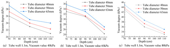
Figure 14.
Variation curve of vertical vacuum degree with tube well diameter.
As can be seen from Figure 14, the trend of the vertical vacuum degree at the three pipe diameters is almost the same. When the tube diameter increases from 40 mm to 50 mm, the vertical vacuum degree at each point has an average increase of 3.2%, 2.9%, and 5.1%, respectively. When the tube diameter increases from 40 mm to 50 mm, the vertical vacuum degree at each point has an average increase of 4.7%, 4.5%, and 5.2%, respectively. The vertical vacuum degree increases with the increase of tube diameter, but the effect of this improvement is not good (compared to changing the vacuum value in the well). This indicates that the increase in tube diameter has little influence on the vertical vacuum degree. The increase of vertical vacuum degree is small when the tube diameter changes. The transfer path transformed by the increased vacuum degree is smaller. The increasing range of the vacuum field is far less than the actual range of the vacuum field, so the range of the vertical vacuum field can be considered unchanged.
From the vertical vacuum transmission attenuation curve of Figure 15, it can be concluded that the transmission attenuation of vertical vacuum degree gradually decreases with the increase of depth. In addition, the law presented by Figure 15a–c is the opposite. This may be due to the vacuum tube at 90 cm being buried improperly or caused by end blockage. As the tube diameter increases from 40 mm to 63 mm successively, the average attenuation of vertical vacuum degree is 0.198~0.2 kPa/cm, 0.195~0.207 kPa/cm, 0.198~0.218 kPa/cm, respectively. It can be found that when the tube diameter increases, the transmission attenuation of the vertical vacuum degree remains unchanged.
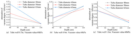
Figure 15.
Variation curve of transmission attenuation of vertical vacuum degree with tube well diameter.
3.3. Influence of Tube Well Burial Depth on Vacuum Degree Transfer
Three types of tube wells of 0.7 m, 0.9 m, and 1.1 m lengths were used to simulate vacuum dewatering tests at different burial depths, and the unified burial depth of the measurement tube was 0.7 m. At the same time, the tube diameter was set to 40 mm to reduce the influence of the tube diameter, and two sets of simulation tests with supplemental in-well vacuum values of 40 kPa and 80 kPa. The variation curve of the vacuum degree with the burial depth of the tube well is obtained, as shown in Figure 16.
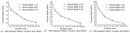
Figure 16.
Variation curve of radial vacuum degree with burial depth of tube well.
As can be seen from Figure 16, the vacuum degree in the vacuum field does not change significantly when the depth of the tube well increases sequentially. For instance, when the burial depth of the tube well is 0.7 m, 0.9 m, and 1.1 m, respectively, the vacuum degree of the No.2 observation hole is 26 kPa, 26 kPa, and 27 kPa, respectively, and the vacuum degree of the No. 3 observation hole is 19 kPa, 20 kPa, and 19 kPa respectively (Take Figure 16a as an example, and other observation holes are similar). The radial vacuum at each points did not produce significant variations. This indicates that increasing the buried depth of the tube well will not affect the radial vacuum degree, and the range expansion of the radial vacuum field is independent of the burial depth of the tube well. Figure 17 is the variation curve of radial vacuum degree transmission attenuation at different burial depths. It can be seen that the transmission attenuation curve of the radial vacuum is essentially the same when the burial depth of the tube well changes. It indicates that increasing the burial depth of the tube well does not affect the attenuation of the radial vacuum degree transmission.The primary reason for this is that the radial transfer fluid path of the vacuum does not change when the burial depth of the tube well changes. The path of radial vacuum transfer and the energy required to overcome the obstruction remains the same. The radial vacuum degree transfer reaches a relatively stable state. As the burial depth of the tube well increases, the vacuum degree at the measurement points farther away from the tube well does not differ much. This indicates that the expansion of the vacuum field in the horizontal direction is independent of the burial depth of the tube well. It can be seen that the change in the burial depth of the tube well does not influence both the radial vacuum and the extent of the vacuum field in the horizontal direction. The primary reason for this is that the path of radial vacuum transfer and the energy required to overcome the obstruction remains the same when the burial depth of the tube well increases.
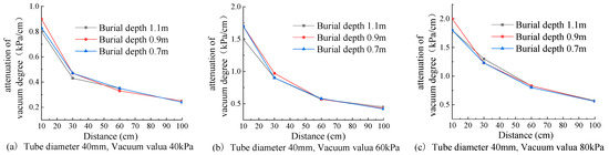
Figure 17.
The variation curve of radial vacuum degree transmission attenuation at different burial depths.
4. Conclusions
Through the vacuum tube, well dewatering test with various in-well vacuum values, tube diameters, tube well burial depths, etc., the change law of vacuum degree under each factor was investigated and mainly obtained the following conclusions.
- (1)
- A laboratory test setup for vacuum tube well dewatering was developed, and the device was composed of six parts: model box, dewatering tube well, water pumping system, air pumping system, measuring system, and sealing system. It effectively solved the problem of poor air tightness and the in-well water entering the vacuum pump. The device’s viability for researching the vacuum degree transfer law in vacuum tube well dewatering was verified after numerous rounds of testing.
- (2)
- With the increase of vacuum value in the well, the radial vacuum degree and vertical vacuum degree have about 14.9~47.7% and 14.9~32.4% increase, respectively, and the range of vacuum field increases. With the outward transmission of the vacuum degree, the transmission attenuation of the radial vacuum degree decreases rapidly and then tends to be stable, and the transmission attenuation of the vertical vacuum degree decreases gradually. When the vacuum value in the well increases, the transmission attenuation of the radial vacuum degree and the vertical vacuum degree increases to a certain extent, this shows that the change of vacuum value in the well will affect the transmission efficiency of the vacuum degree.
- (3)
- The increase in pipe diameter can improve the radial and vertical vacuum degree in the vacuum field, but the effect of this improvement is not good. Its increasing margin is 5.4~11.9% and 2.9~5.2%, respectively. The change in tube diameter will not affect the range of the vacuum field. When the tube diameter increases, the transmission attenuation of the radial vacuum degree initially reduces and then stays constant, whereas the transmission attenuation of the vertical vacuum degree stays the same.
- (4)
- By comparing and analyzing the measured data under different buried depths, it is found that when the buried depth of the tube well increases, the radial vacuum degree, the range of the radial vacuum field, and the transmission attenuation of the radial vacuum degree do not change obviously.
Based on the laboratory model test of vacuum tube well dewatering, the distribution law of vacuum degree under different influencing factors is initially derived, and there is still a need to continue the relevant research in the actual engineering of vacuum dewatering in clayey silt foundation pits to guide the actual engineering.
Author Contributions
Conceptualization, Y.Y. and J.T.; writing—review and editing, Y.Y. and J.Z.; writing—original draft preparation, J.T.; investigation, L.F.; resources, J.T., C.G., J.Z. and J.Y.; funding acquisition, Y.Y. and L.F. All authors have read and agreed to the published version of the manuscript.
Funding
This research was funded by the General Project of the National Natural Science Foundation of China (grant number 52208244) and the Henan Province Science and Technology Research Funding Project (grant number 222102320034).
Institutional Review Board Statement
Not applicable.
Informed Consent Statement
Not applicable.
Data Availability Statement
Not applicable.
Acknowledgments
The writers wish to thank the National Fund Committee for its financial support for this study, as well as the staff of the School of Civil Engineering, Henan Polytechnic University, for their help and valuable contributions.
Conflicts of Interest
The authors declare no conflict of interest.
References
- Liu, N.; Wan, Y.H.; Cao, C.Y.; Liu, X.Y. Innovative solutions for layout planning and implementation of a metro station and its accessory structures in mountainous cities, China. Tunn. Undergr. Space Technol. 2022, 129, 104670. [Google Scholar] [CrossRef]
- Zeng, C.F.; Zheng, G.; Xue, X.L.; Mei, G.X. Combined recharge: A method to prevent ground settlement induced by redevelopment of recharge wells. J. Hydrol. 2018, 568, 1–11. [Google Scholar] [CrossRef]
- Cao, C.Y.; Shi, C.H. Analytical procedure for massive water-sealing barriers used in deep excavations considering seepage effect and its application. J. Cent. South Univ. 2022, 29, 2033–2048. [Google Scholar] [CrossRef]
- Zhou, F.C.; Zhou, P.; Li, J.Y.; Lin, J.Y.; Ge, T.C.; Deng, S.M.; Ren, R.; Wang, Z.J. Deformation characteristics and failure evolution process of the existing metro station under unilateral deep excavation. Eng. Fail. Anal. 2022, 131, 105870. [Google Scholar] [CrossRef]
- Wu, Y.X.; Zheng, Q.; Zhou, A.N.; Shen, S.L. Numerical evaluation of the ground response induced by dewatering in a multi-aquifer system. Geosci. Front. 2021, 12, 101209. [Google Scholar] [CrossRef]
- Chen, Z.; Huang, J.T.; Zhan, H.B.; Wang, J.G.; Dou, Z.; Zhang, C.J.; Chen, C.S.; Fu, Y.S. Optimization schemes for deep foundation pit dewatering under complicated hydrogeological conditions using MODFLOW-USG. Eng. Geol. 2022, 303, 106653. [Google Scholar] [CrossRef]
- Zeng, C.F.; Song, W.W.; Xue, X.L.; Li, M.K.; Bai, N.; Mei, G.X. Construction dewatering in a metro station incorporating buttress retaining wall to limit ground settlement: Insights from experimental modelling. Tunn. Undergr. Space Technol. 2021, 116, 104124. [Google Scholar] [CrossRef]
- Hong, C.Y.; Zhang, J.Y.; Chen, W.B. An Integrated Intelligent Approach for Monitoring and Management of a Deep Foundation Pit in a Subway Station. Sensors 2022, 22, 8737. [Google Scholar] [CrossRef]
- He, Y.Y.; Sun, B.L.; Wang, M.N. Study on Stability of Tunnel Surrounding Rock and Precipitation Disaster Mitigation in Flowing Sand Body. Geofluids 2021, 2021, 6043807. [Google Scholar] [CrossRef]
- Zou, B.; Song, C.Y.; Zhang, D.D.; Chen, L.Z.; Chen, B. Numerical simulation of high vacuum dewatering in low permeability soil. J. Harbin Inst. Technol. 2018, 50, 78–83. (In Chinese) [Google Scholar]
- Zhang, G.X.; Mo, H.Y.; Dong, Z.L.; Zhao, J.G. Analysis of relationship between vacuity and pore-water pressure in vacuum preloading. Rock Soil Mech. 2005, 26, 1949–1952. (In Chinese) [Google Scholar]
- Stewart, L. Analytical Solutions for Steady-State Gas Flow in Layered Soils with Field Applications. Groundw. Monit. Remediat. 2022, 42, 35–46. [Google Scholar] [CrossRef]
- Huang, F.; Wang, G. The Influence of Air Injection on Effects of Vacuum Dewatering: Experimental Study on Vacuum-air Injection Dewatering Method. Electron. J. Geotech. Eng. 2012, 17, 2913–2923. [Google Scholar]
- Huang, F.; Lyu, J.G.; Gao, H.; Yu, Z.T. Groundwater Level Distribution in Vacuum Dewatering Method in Phreatic Aquifer. Geofluids 2018, 2018, 8459289. [Google Scholar] [CrossRef]
- Huang, F.; Lyu, J.G.; Wang, G.H.; Liu, H.Y. One-Dimensional Vacuum Steady Seepage Model of Unsaturated Soil and Finite Difference Solution. Math. Probl. Eng. 2017, 2017, 9589638. [Google Scholar] [CrossRef]
- Jia, X.X.; Nie, Q.K.; Wang, Y.H.; Liang, S.Q. Analysis and numerical simulation of vacuum well point dewatering test. Rock Soil Mech. 2014, 35, 607–612+618. (In Chinese) [Google Scholar]
- Vu, V.T.; Yao, L.H.; Wei, Y.J. Laboratory investigation of axisymmetric single vacuum well point. J. Cent. South Univ. 2016, 23, 750–756. [Google Scholar] [CrossRef]
- Zhou, Y.F.; Wang, P.; Shi, L.; Cai, Y.Q.; Wang, J. Analytical solution on vacuum consolidation of dredged slurry considering clogging effects. Geotext. Geomembr. 2021, 49, 842–851. [Google Scholar] [CrossRef]
- Zhu, J.C.; Wen, X.G.; Gong, X.N.; Cen, Y.R. Analysis of factors having effect on distribution of vacuum degrees during soft ground by vacuum drainage preloading. J. Harbin Inst. Technol. 2003, 35, 1399–1401+1404-1408. (In Chinese) [Google Scholar]
- Geng, X.Y.; Buddhima, I.; Cholachat, R. Analytical Solutions for a Single Vertical Drain with Vacuum and Time-Dependent Surcharge Preloading in Membrane and Membraneless Systems. Int. J. Geomech. 2012, 12, 27–42. [Google Scholar] [CrossRef]
- Bao, S.F.; Mo, H.O.; Dong, Z.L.; Chen, P.S.; Qiu, Q.Z. Research on transfer properties and distribution model of negative pressure in fresh hydraulic reclamation muck foundation. Rock Soil Mech. 2014, 35, 3569–3576. (In Chinese) [Google Scholar]
- Zeng, B.; Zhen, Y.; Zhang, D.W.; Meng, T.; Gong, Z.J.; Liu, S.Y. A case study of vacuum tube-well dewatering technology for improving deep soft soil in Yangtze River floodplain. Environ. Earth Sci. 2021, 80, 598. [Google Scholar] [CrossRef]
- Li, L.H.; Wang, Q.; Wang, N.X.; Wang, J.P. Vacuum dewatering and horizontal drainage blankets: A method for layered soil reclamation. Bull. Eng. Geol. Environ. 2009, 68, 277–285. [Google Scholar] [CrossRef]
- Jiang, Y.B.; He, N.; Xu, B.H.; Zhou, Y.Z.; Zhang, Z.L. Model tests on negative pressure distribution in vacuum preloading. Chin. J. Geotech. Eng. 2017, 39, 1874–1883. (In Chinese) [Google Scholar]
- Hu, Y.Y.; Qian, J.L.; Zhang, C.J. Distribution patterns of final negative pressure in vacuum preloading. Chin. J. Geotech. Eng. 2019, 41, 1139–1148. (In Chinese) [Google Scholar]
- Hu, Y.Y. Consolidation solution for sand-drained ground with impeded boundaries under vacuum preloading. Adv. Eng. Sci. 2018, 50, 32–41. (In Chinese) [Google Scholar]
- Khan, A.Q.; Mesri, G. Vacuum distribution with depth in vertical drains and soil during preloading. Geomech. Eng. 2014, 6, 377–389. [Google Scholar] [CrossRef]
- Lyu, H.M.; Shen, S.L.; Wu, Y.X.; Zhou, A.N. Calculation of groundwater head distribution with a close barrier during excavation dewatering in confined aquifer. Geosci. Front. 2021, 12, 791–803. [Google Scholar] [CrossRef]
- Yan, Y.Z. Experimental study on vacuum degree transfer law of soft clay of different grain size grading under vacuum preloading. Port Waterw. Eng. 2010, 10, 109–112. (In Chinese) [Google Scholar]
- Shan, W.C.; Chen, H.E.; Yuan, X.Q.; Ma, W.L.; Li, H. Mechanism of pore water seepage in soil reinforced by step vacuum preloading. Bull. Eng. Geol. Environ. 2021, 2021, 2777–2787. [Google Scholar] [CrossRef]
- Chen, L.; Zhang, H.F.; Li, Z.P.; An, Y.Y.; Li, Y.L. Experimental study on radial consolidation of soil around drainage plate. Chin. J. Geotech. Eng. 2016, 38, 163–168. (In Chinese) [Google Scholar]


Publisher’s Note: MDPI stays neutral with regard to jurisdictional claims in published maps and institutional affiliations. |
© 2022 by the authors. Licensee MDPI, Basel, Switzerland. This article is an open access article distributed under the terms and conditions of the Creative Commons Attribution (CC BY) license (https://creativecommons.org/licenses/by/4.0/).