Article

Effect of Using ECC Layer on the Flexural Performance of RC Beams Previously Strengthened with EB CFRP Laminates

1
Structural Engineering Department, Faculty of Engineering, Zagazig University, Zagazig P.O. Box 44519, Egypt
2
Department of Civil Engineering, Delta Higher Institute for Engineering & Technology, Talkha 35681, Egypt
3
Department of Engineering and Technology, Texas A&M University-Commerce, Commerce, TX 75429, USA
*
Author to whom correspondence should be addressed.
Sustainability 2022, 14(24), 16990; https://doi.org/10.3390/su142416990
Submission received: 25 October 2022 / Revised: 9 December 2022 / Accepted: 16 December 2022 / Published: 18 December 2022
(This article belongs to the Special Issue Intelligent Sustainable Buildings and Information Technologies)

Abstract

:
This paper studies the efficiency of applying an engineered cementitious composite (ECC) layer to the tensile surface of (RC) beams that were previously strengthened using externally bonded (EB) carbon fiber-reinforced polymer (CFRP) laminates. One control and ten strengthened RC beams were produced and tested utilizing a four-point loading regime. For strengthened beams, two beams were kept strengthened using only CFRP, and additional ECC layers were added to the rest of the strengthened beams. The CFRP width and overlap length and position were among the test factors. Experimental results revealed that strengthening RC beams with CFRP laminates enhanced both the stiffness and flexural capacity of beams. Additional enhancements were obtained through the application of the additional ECC layers. The existence of the ECC layer alongside the CFRP laminate improved the flexural capacity by 102% and 125% when using CFRP widths of 50 mm and 100 mm, respectively, and the stiffness was improved by an average value of 318%. Three-dimensional (3D) finite element models (FEMs) were developed using ABAQUS software and verified against the experimental results to model the response of the tested beams. The verified model was used to conduct a parametric study to consider the effect of the ECC layer thickness and the reinforcement ratio on the strengthened beam behavior. The numerical results revealed that the effect of the reinforcement ratio was more significant than the ECC layer thickness in enhancing the load-displacement response, especially after the cracking stage.

1. Introduction

Due to its economic effectiveness, strengthening and upgrading degraded and aging structures/structural members is a frequent practice today. Over the previous decades, numerous procedures and strengthening materials have emerged. Recently, several approaches have emerged which can be followed for the strengthening process of Reinforced Concrete (RC) elements. For the flexural strengthening of RC beams, the most common approaches are Near Surface Mounted (NSM), Externally Bonded Reinforcement (EBR), Textile Reinforced Mortar (TMR), and reinforced/non-reinforced High-Performance Concrete (HPC) layers [1,2,3,4,5,6,7]. Both NSM and EBR techniques extensively use steel and fiber-reinforced polymers (FRP) as reinforcing and retrofit materials. Due to their advantages over traditional steel, such as its non-corrosive nature, high tensile strength, ease of handling, strength-to-weight ratio, and resistance to chemical attacks, FRP materials are now employed extensively [8,9]. Per ton of production, FRP emits significantly fewer emissions than steel. FRP-reinforced beams use approximately half as little energy and emit 43% less carbon dioxide than steel [10]. Therefore, these materials present a feasible and cost-effective solution in which environmental sustainability plays a significant role. On the other hand, the existence of epoxy resins in FRP presents the main drawback resulting in its high cost, inadequate behavior at high temperatures, and inadequacy to be applied on wet surfaces or low temperatures [11,12,13,14].
On the tension side of the concrete element, longitudinal grooves are cut using the NSM method, in which bars or strips are inserted into the concrete surface utilizing an adhesive [15,16]. For the EBR technique, FRP sheets/laminates or steel plates are bonded to the tensile surface of concrete for flexural strengthening [17,18]. In addition, the NSM approach has potential advantages over the EBR technique, including quicker installation and improved resistance to environmental regimes such as temperature and humidity [19]. One critical aspect concerning the EBR is its undesirable failure modes such as plate-end cover separation and plate-end interfacial debonding [20,21,22,23], while concrete cover separation and the bar–epoxy surface debonding are the most critical NSM failure modes [24,25,26]. Premature failure is caused by cracks that start at the ends of the FRP strips or intermediate cracks that spread and cause tensile flexural failure [27,28]. The concrete cover is a weakness for both NSM and EBR approaches. In addition, using the NSM approach needs extra time, effort, and safety measures.
Another popular strengthening method that may be seen as a logical progression of FRP, since it gets over the issues with FRP epoxy, is the usage of TRM. TRM is made up of FRP in the form of textiles that are embedded in the inorganic matrix such as mortar that is made of cement. TRM is appropriate for wet surfaces, extremes in ambient temperature, and concrete substrates [2,29,30]. TRM may be used for the seismic retrofitting of RC components, the jacketing of RC columns, and the flexure strengthening of RC beams [31,32,33]. The application of an HPC layer to the tension side of an RC beam is another popular method for flexural strengthening. According to previous studies, strengthening RC elements with an ultra-high performance concrete (UHPC) covering increased their tensile properties, cracking resistance, and fracture progress control [34,35,36,37,38,39,40]. On the other hand, the strengthening of RC beams through the application of the UHPC layer reduced its ability to sustain inelastic deformation before failure. Additionally, the given UHPC layer’s microcracks reduced its ductility and caused the tensile reinforcement to prematurely break. For this, additional reinforcement in the strengthening layers should be considered. The formation of micro-cracks can be controlled using fiber-reinforced concrete however this may result in a high tensile reinforcement ratio causing over-reinforced failure of the strengthened beam [39]. Engineered Cementitious Composites (ECC) are a different variety of HPC concrete. ECC is characterized by its increased durability in harsh weather conditions and greater tensile strength. Additionally, when compared with normal concrete, ECC has strain hardening and several, narrower fractures that increase ductility, prevent localized cracking, and better protect the reinforcing steel [41,42,43,44]. Studies showed that the use of ECC improved the flexural capacity, ductility, and failure of composite structures [45,46,47]. Moreover, after first cracking, ECC exhibited strain-hardening instead of tension-softening, which is exhibited in normal fiber-reinforced concrete.
Today, according to the competencies of both ECC and FRP, in conformity with keeping away from the FRP’s untimely failure, a hybrid ECC-FRP technique is being considered a promising technique that could improve the toughness of RC elements. Zhou et al. [48] investigated the flexural efficiency of RC beams reinforced with composite CFRP and ECC layers. Combinations of these layers improved the flexural capacity, ductility, and fracture width management at the maximum loads. In addition, CFRP rupture, rather than debonding, was the mode of failure. Hu et al. [49] studied the flexural response of RC beams with varying degrees of corrosion in steel rebars. Hybrid ECC-CFRP and ECC layers were used for strengthening these beams. The RC beams with hybrid ECC-CFRP exhibited flexural performance, cracking, yielding loads, and stiffness much better than that of beams retrofitted with ECC only. Moreover, at high levels of steel corrosion, strengthening with the ECC layer could not recover the beam to its original conditions but the use of hybrid ECC-CFRP could. Another study, carried out by Li et al. [50], confirmed that strengthening RC beams using an ECC layer reinforced with basalt FRP (BFRP) increased the load-carrying capacity by about 47.1%.
Because of the fast development of the construction industry and changes in the usage of buildings, the problem of how to enhance the performance of structural sections that have already been strengthened arises. In addition, there is no previous research available in the literature concerning the addition of the ECC strengthening technique to RC beams that were previously strengthened with CFRP laminates. Therefore, this paper looks at how applying an ECC layer to RC beams that have previously been strengthened with EB ECC-CFRP laminates enhances their flexural performance. One control and ten strengthened RC beams were subjected to a four-point loading regime up to failure. Two beams were strengthened using only CFRP, and the rest of the tested beams were strengthened with additional ECC layers alongside the CFRP. The main parameters were the CFRP width and the overlap of length and position. Numerical analysis was implemented to model the response of the RC beams strengthened using CFRP laminates and ECC overlay. Three-dimensional (3D) finite element models (FEMs) were developed using ABAQUS software and verified against the experimental results. The verified model was used to conduct a parametric study to investigate the response of strengthened beams while changing either the reinforcement ratio or the thickness of the ECC layer.

2. Experimental Work

2.1. Details of Specimens and Test Matrix

A total of eleven simply supported RC beams were manufactured. Each had a total length of 1500 mm (1300 mm clear span), with a cross-section of 150 mm in width (b), and an overall height (h) of 260 mm. The beams were designed according to the ECP 203 [51]. To ensure that all the beams were subjected to flexural failure, the stirrups in the shear span were arranged with a spacing of 130 mm. The detailed beam configurations are shown in Figure 1 and listed in Table 1.
The main parameters of the study were the CFRP laminate width, the length and position of the CFRP laminates overlap, and the existence of an additional ECC layer attached to the tension surface of the RC beam. Therefore, the first column in Table 1 illustrates the specimen’s ID. The second column shows the width of the CFRP layer (50 mm and 100 mm). Then, the third column presents the overlap length of the CFRP laminates (if any) and the fourth column indicates the existence of the ECC layer or not. One beam was used as a control one without strengthening (beam B1) as shown in Figure 1a. Six RC beams were cast and strengthened as follows: one beam was strengthened using a 100 mm-wide CFRP laminate (beam B2), another beam was strengthened using a full-length CFRP laminate and a 30 mm ECC layer (beam B3), as shown in Figure 1b, and four RC beams were strengthened using an ECC layer in addition to overlapped CFRP laminates with different overlapping lengths (beams B4, B5, B6, and B6), as listed in Table 1 and shown in Figure 1c. To investigate the effect of CFRP width on the behavior of RC beams, four more beams were strengthened using CFRP laminates of 50 mm in width as follows: one beam was strengthened using a full-length CFRP laminate only (beam B8), one beam was strengthened using CFRP laminate and an ECC layer (beam B9), and the last two beams (beams B10 and B11) were strengthened using an ECC layer and CFRP laminates overlapped at different positions, as listed in Table 1. The overlap parameter was investigated to consider the case of using two CFRP strips in series. Therefore, it was important to consider the continuity between the two strips by applying overlap.

2.2. Materials Properties, Mix Proportions, and Specimen Preparation

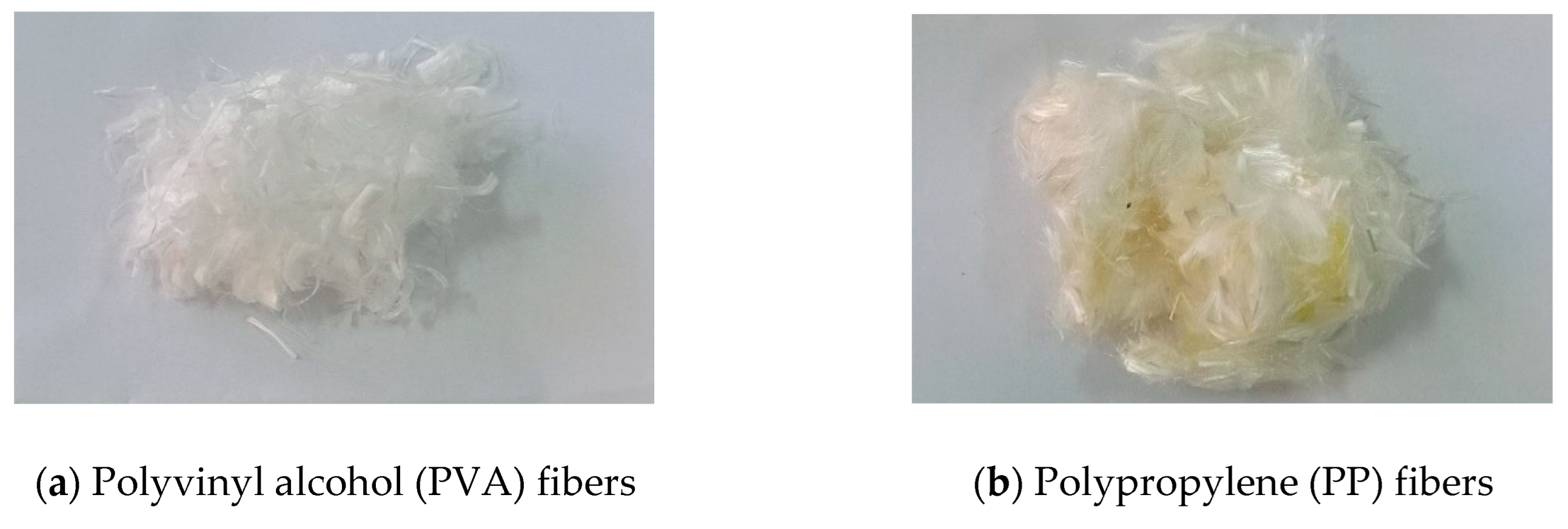
Normal Concrete (NC) and ECC mixtures were used in the current study and the mixing proportions for each mixture are presented in Table 2. For NC, Ordinary Portland Cement, crushed limestone of 10 mm maximum nominal size as coarse aggregate, natural siliceous sand as fine aggregate, and tap water were used. On the other hand, Ordinary Portland cement, fly ash, silica sand with a maximum size of 250 µm, high-range water reducer, tap water, polyvinyl alcohol (PVA) fibers (Figure 2a), and polypropylene (PP) fibers (Figure 2b) were the main ingredients for the ECC. The tensile and compressive stress–strain relationships of ECC specimens utilized in this research are presented in Figure 3. The properties of the PP and PVA fibers are presented in Table 3. For both NC and ECC, the compressive strength was determined as an average result of three tested standard cylinders of 150 mm in diameter and 300 mm in height.
The control beam was designed to ensure flexural failure mode and avoid compression failure according to the ECP 203 [51]. For this reason, deformed steel rebars of 10 mm diameter, 360 MPa yield strength, and 520 MPa ultimate strength, according to the supplier datasheet, were used as the main longitudinal tension and compression reinforcement while 8 mm plain steel rebars of yield strength and ultimate strength of 240 MPa and 350 MPa, respectively, were used for the stirrups (see Figure 1).
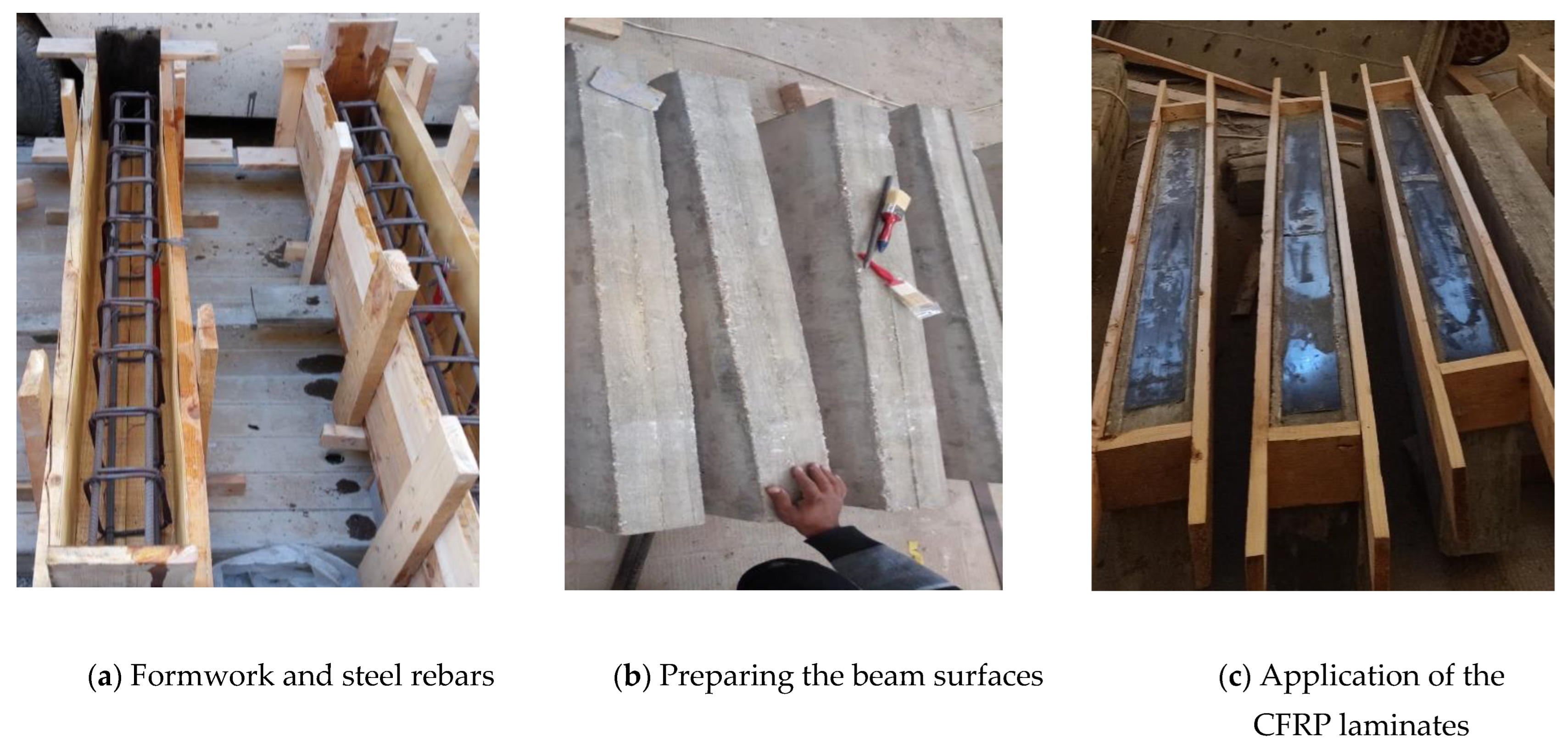
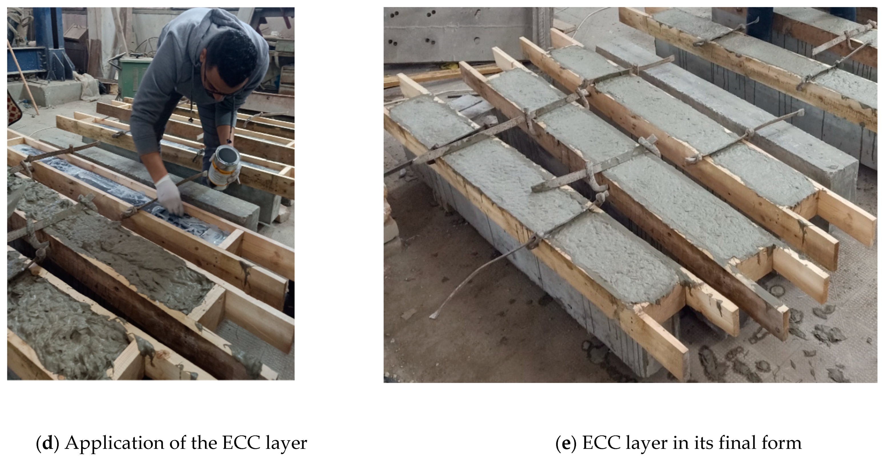
Two types of CFRP laminates, namely CARBODUR 1012SK and CARBODUR 512SK, with a width of 100 mm and 50 mm, respectively, were used. Both types of CFRP have tensile strength and modulus of elasticity of 3100 MPa and 170 GPa, respectively, with 1.8% elongation at failure. Two-component epoxy resins with the commercial names SIKADUR®-30LP and SIKADUR®-32LP were employed for the bonding between the hardened concrete surface and CFRP laminates as well as between the CFRP laminates and the applied fresh ECC layer, respectively. The CFRP laminates were applied first to the tension surface of the RC beam and, after curing, the ECC layers were applied to the designated strengthened beams as shown in Figure 4.

2.3. Test Setup and Instrumentations

All beams were tested in flexural under a four-point loading regime (see Figure 5). The load was applied using a 2000 kN hydraulic testing machine under displacement-controlled loading with a loading rate of 0.5 mm/min to detect the softening after the peak. The load was applied using a single hydraulic jack and was distributed to two points loading using a spreader beam. The applied loads and the mid-span deflections were recorded by a calibrated load cell and linear variable differential transducer (LVDT).

3. Test Results and Discussions

3.1. Ultimate Flexural Capacities and Deformations

Table 4 lists the experimental results in terms of the applied loads and their corresponding displacements at the cracking, yielding, and ultimate stages. The obtained values were determined from the load-displacement relationship as illustrated in Figure 6. Moreover, the initial stiffness (K) and the observed failure mode are presented in Table 4.
The load-displacement relationships of the tested beams are illustrated in Figure 7. Determined by two turning points indicating the concrete cracking and steel yielding, all tested specimens showed almost similar behaviors as the curves might be split into three phases, namely the cracking stage, yielding stage, and ultimate stage. Results revealed that strengthening RC beams with CFRP laminates had almost no effect on the cracking load while the yielding load and ultimate load increased by 28% and 29%, respectively, due to the use of the 100 mm-width CFRP laminate (beam B2), thus increasing the elastic stiffness of B2 compared with the control beam. These improvements were only 7% and 16% for the beams strengthened using the 50 mm-width CFRP laminate (beam B8). Moreover, the application of CFRP led to a reduction in the reinforcing steel axial strain as illustrated in Figure 7a,b. Doubling the CFRP width increased both the cracking load and the ultimate load by 20% and 11%, respectively, as presented in Table 4.
As shown in Figure 7a, the two strengthened beams B2 and B8 with CFRP widths of 50 mm and 100 mm, respectively, exhibited the same initial stiffness, which was about 67% higher than the control specimen. However, the two beams became stiffer after reaching the cracking load as more resistance was provided by the CFRP resulting in lower strain in the main reinforcement as shown in Figure 8. Moreover, the wider the CFRP, the more stiffness was gained and the lower strains were captured in the longitudinal reinforcement (see Figure 8).
The effect of using the ECC layers alongside CFRP laminates can be shown in Figure 7b. The existence of an additional ECC layer improved the overall load-displacement behavior of the tested beams. The observed improvement was significant at all loading stages. With respect to the control beam (B1), the use of ECC in addition to the 100 mm-width CFRP laminate for beam B3 increased the cracking, yielding, and ultimate loads by about 63%, 113%, and 125%, respectively, whereas the observed corresponding displacements decreased by about 49%, 6%, and 39%, respectively. For beam B9 with the 50 mm-width CFRP laminate, the ECC layer provided slight effects on the cracking and yielding loads. However, this effect was significant at the ultimate stage as the ultimate load increased by 11.6%. In general, the additional ECC layer increased the depth of the RC beams and enhanced the overall stiffness thus improving the behavior at both yielding and ultimate stages. Moreover, the higher tensile strength of the ECC retarded the crack initiation and increased the cracking load of strengthened beams.
The effect of the overlap length is illustrated in Figure 7c. The yielding loads and ultimate capacities of the strengthened beams were enhanced as the laminate overlap length at the mid-spans increased, while no notable change was observed regarding the cracking load. For the overlap lengths 100 mm, 200 mm, and 300 mm, the yielding load increased by about 24%, 26%, and 33%, respectively, compared with the beam without overlap (B3). These improvements were about 8%, 23%, and 20%, respectively, in the ultimate capacities. Compared with the control beam, the mid-span deflections for all strengthened beams were reduced by 65 % and 77 % for the cases of 50 mm and 100 mm CFRP width, respectively. It is worth mentioning that beam B6 exhibited higher yielding load and stiffness compared with B5 (with shorter overlapping length) however the Pu of B6 is lower than that of B5 by about 2%. This can be attributed to the intermediate crack debonding that was observed in B6 and resulted in premature failure. Under the identical strengthening configurations (50 mm CFRP laminate combined with an ECC layer) with various overlap positions, specimen B11, with a 100 mm third-span overlap, had a 10% lower flexural capacity and higher mid-span displacement than specimen B10, with a 100 mm mid-span overlap, however the enhancement strained capacity. This can be attributed to the higher mid-span stiffness of B10 compared with B11.

3.2. Modes of Failure and Cracking Patterns

The observed mode of failure for the control specimen (B1) was the typical flexural failure mode, in which mid-span flexural cracks were first observed then followed by steel yielding and concrete crushing as shown in Figure 9a. At 25% of the ultimate load, the formation of the initial cracks started and then more cracks were created and propagated as the applied load increased. Before the failure, yielding in the tension steel rebars occurred when the applied load reached 83% of the ultimate load, as illustrated in Figure 8. For the beams strengthened with CFRP laminates only (B2 and B8), the mode of failure was severe shear cracks accompanied by the debonding of the CFRP strips and concrete cover separation, as shown in Figure 9b,h. None of the strengthened beams experienced any intermediate debonding at the ECC-to-concrete interface, demonstrating that this sort of strengthening approach was effective in minimizing flexural crack-induced debonding failure. For beams with the ECC layers accompanied by a 100 mm width of CFRP and overlapped at the mid-span (B3, B4, B5, and B7), the first flexural cracks were initiated at a load range between 16% and 20% of their ultimate loads. By increasing the applied load, shear and flexural cracks were created and grew in the direction of the compression zone, as shown in Figure 9c–e,g. Moreover, insufficient shear resistance caused a large shear stress concentration at the end of the CFRP laminate layer resulting in debonding at the interface between the strengthening ECC layer and the concrete substrate for beams B3 and B7. The same behavior was observed for beam B9, in which the growth of the shear crack resulted in the slippage of the CFRP laminate in addition to the debonding at the ECC–concrete interface accompanied by concrete crushing in the compression zone as shown in Figure 9i. For beam B6, a major wide crack was initiated in the ECC layer due to the rupture of the layer at the mid-span and then progressively extended to the ECC–concrete interface, resulting in CFRP slippage, and then propagated up towards the loading plates under which the concrete was crushed as illustrated in Figure 9f. Some other traditional flexural cracks were registered with the increase in loading. Similar to specimen B6, both specimens B10 and B11 demonstrated a significant wide crack that started in the ECC layer but at the shear span and gradually spread to the ECC–concrete interface. These cracks were accompanied by numerous flexural-shear cracks and concrete crushing at the loading point, as depicted in Figure 9i,k, respectively. Additionally, in beam B11, a separation between the two overlapped CFRP laminates was noticed.

3.3. Stiffness of the Tested Beams

The elastic stiffness values are listed in Table 4. These values were calculated by dividing the cracking load (Pcr) by the corresponding displacement (∆c) as demonstrated in Figure 6. The obtained results emphasized that the application of CFRP as an s strengthening technique could significantly enhance elastic stiffness. Regardless of the CFRP width, the application of CFRP only (B2 and B8) increased the elastic stiffness by about 15.5% compared with the control beam (B1). Additional elastic stiffness was exhibited after the application of the ECC layers to the tension surfaces. The increase in the stiffness for beams B3 and B9 (with ECC layer and CFRP without overlap) was almost twice that of beams B2 and B8 (with CFRP only). Compared with the specimen without CFRP overlap (B3 and B9), a slight increase in the elastic stiffness was registered due to the application of 100 mm CFRP overlap at the mid-span (beams B4 and B10). Moreover, increasing the overlap length to 200 mm and 300 mm (beams B4 and B6) significantly increased the beam stiffness by about 60% and 134%, respectively, when compared with beam B3 without CFRP overlap.

4. Finite Element Modeling

Numerical analysis was implemented to model the response of the RC beams strengthened using CFRP laminates and ECC overlay. Three-dimensional (3D) finite element models (FEMs) were developed using ABAQUS software and verified against the experimental results. The verified model was used to conduct a parametric study to consider the effect of various parameters that affect the strengthened beam behavior.

4.1. Model Built-Up and Interaction Properties

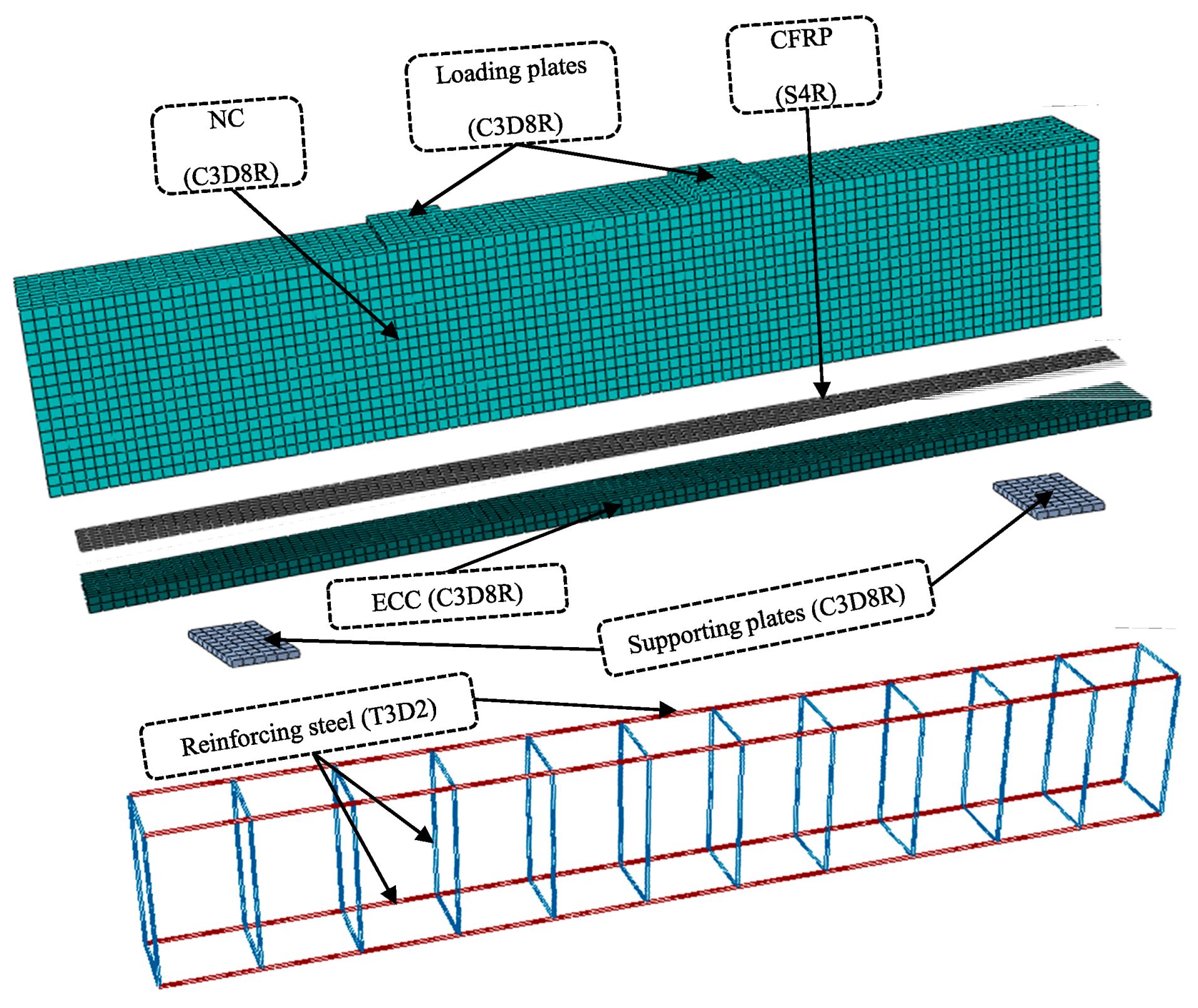
The dimensions of the tested beams were utilized in the FEMs. The NC, ECC, loading plates, and supporting plates were modeled using eight-node solid elements with linear reduced integration (C3D8R). The longitudinal and transverse steel rebars were modeled using two-node linear 3D truss elements (T3D2). The CFRP laminates were simulated using four-node shell elements (S4R) and the contact between the concrete substrate and CFRP was modeled using the cohesive element (COH3D8). The finite element mesh and elements are shown in Figure 10. The FE mesh plays an important role in the FE analysis [52]. Decreasing the size of elements could improve the precision of the analysis, but it is time-consuming. Various element sizes were investigated to choose the optimum density of the FE mesh and the mesh size was selected to be 15 mm.
The load was applied through two reference points linked to the loading plate surface. The contact between the steel rebars and concrete was simulated through the embedded region constraint. The concrete was defined as the host region while steel elements were defined as the embedded one. The interaction between the NC beam and the ECC layer was simulated through surface-to-surface contact considering the cohesive behavior.

4.2. Material Constitutive Models

The Concrete Damage Plasticity (CDP) model was utilized to model both tensile and compressive behaviors of the NC and ECC layers. The CDP parameters were determined through a sensitivity study. Based on the results, the dilation angle (ψ) was defined to be 25° for NC and 30° for ECC. The rest of the parameter values were selected as recommended by ABAQUS to be 0.1, 1.16, 0.667, and 0.001 for the flow potential eccentricity (e), the ratio of the biaxial to uniaxial compressive strength (fb0/fc0), the ratio (Kc), and the viscosity parameter (μ), respectively. Reinforcing steel response was modeled through the elastic perfectly plastic behavior while the CFRP was identified using the lamina properties with Hashin’s failure criteria.

4.3. Validation of the FEMs

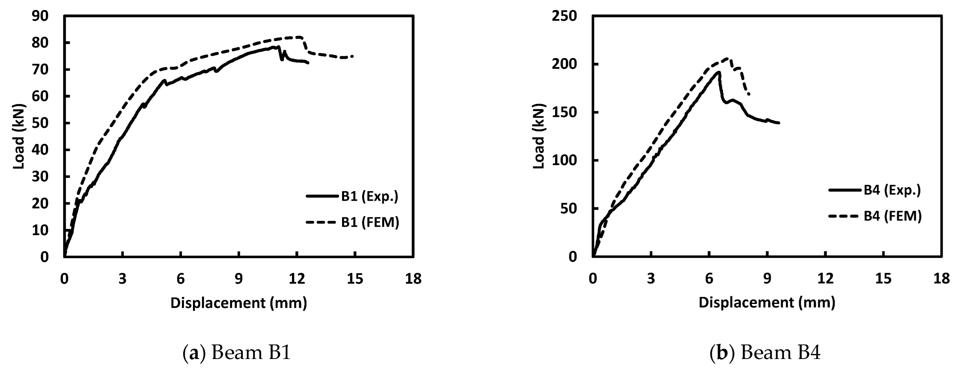
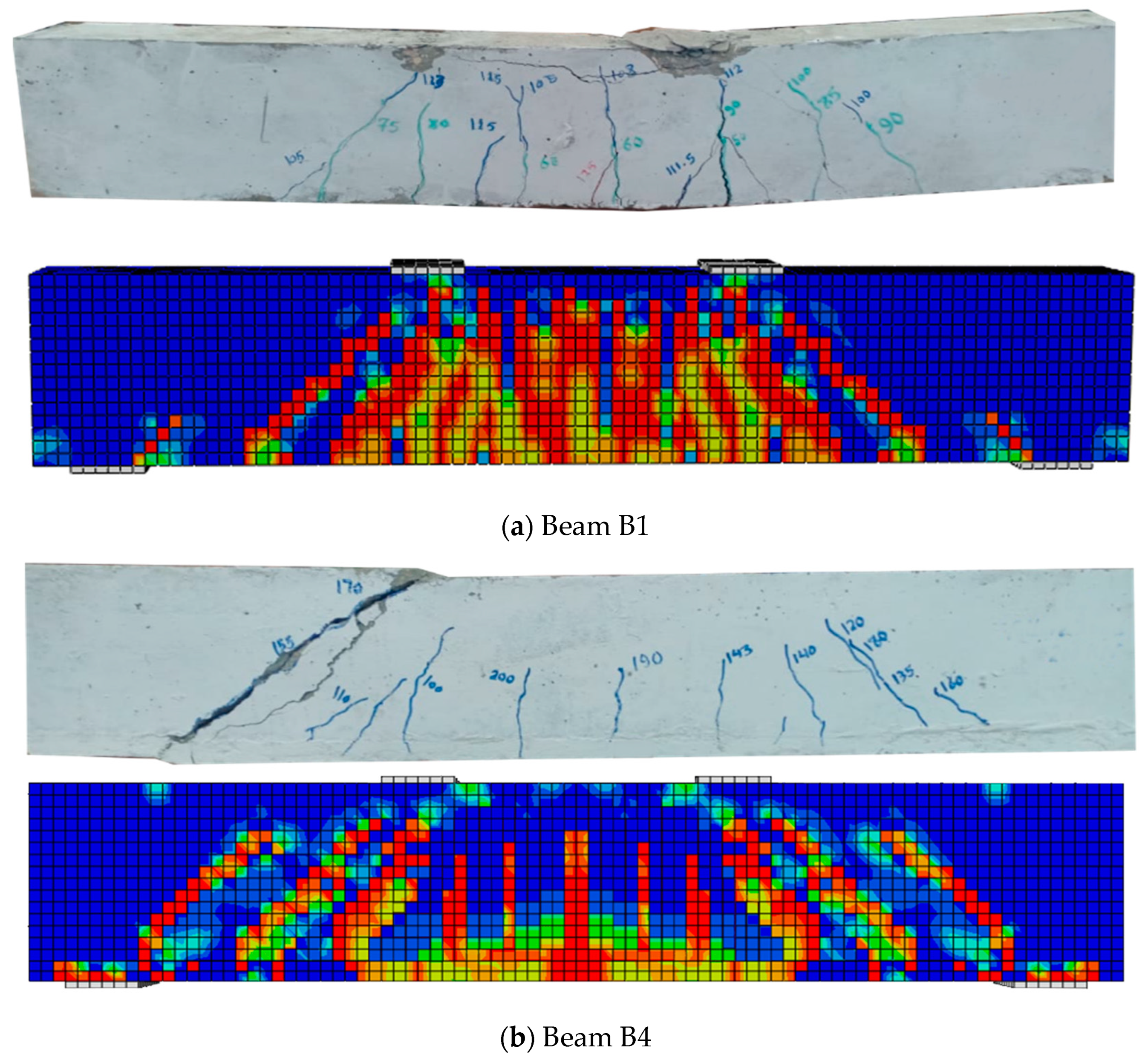
In Figure 11 and Figure 12, the load-displacement response and the crack patterns obtained from the FEMs were compared with the experimental result to assess the reliability of the FEMs. The control beam (B1) and one strengthened beam (B4) were chosen for validation. Results confirmed the ability of the FEMs to simulate the overall performance of the strengthened beams. The FEMs overestimated the load-carrying capacity by about 7%. This could be attributed to the constitutive models of materials as well as the bond behavior of the different components of the FEMs. Furthermore, the FEMs were able to forecast the failure and crack patterns as illustrated in Figure 12.

5. Parametric Study

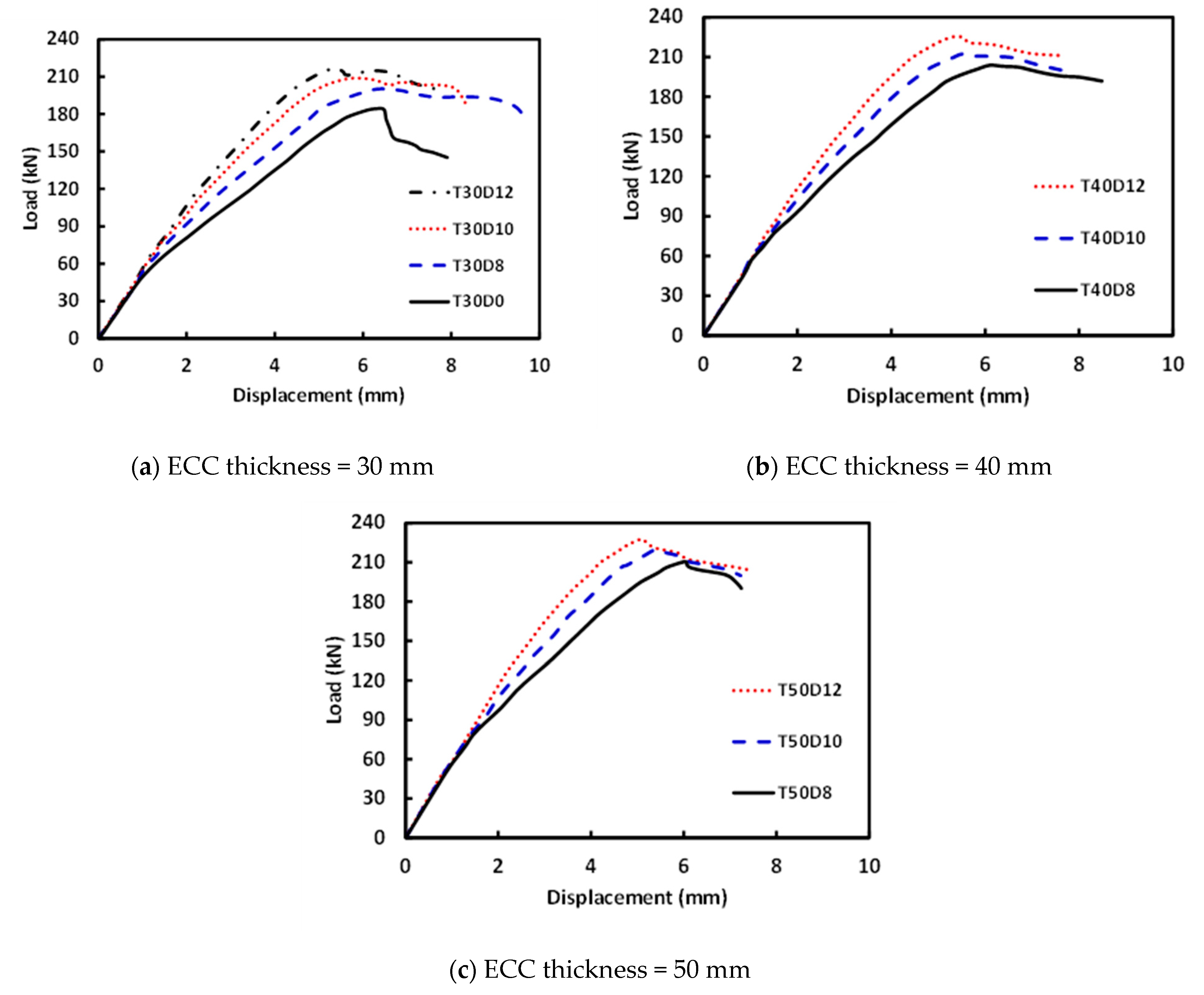
In this section, a parametric study was performed employing the FEMs to investigate the effect of the ECC layer thickness and reinforcement ratio, as listed in Table 5. For the specimen IDs presented in Table 5, the letter T is followed by the thickness of the ECC layer then the letter D is followed by the diameter of the reinforcing steel bars.
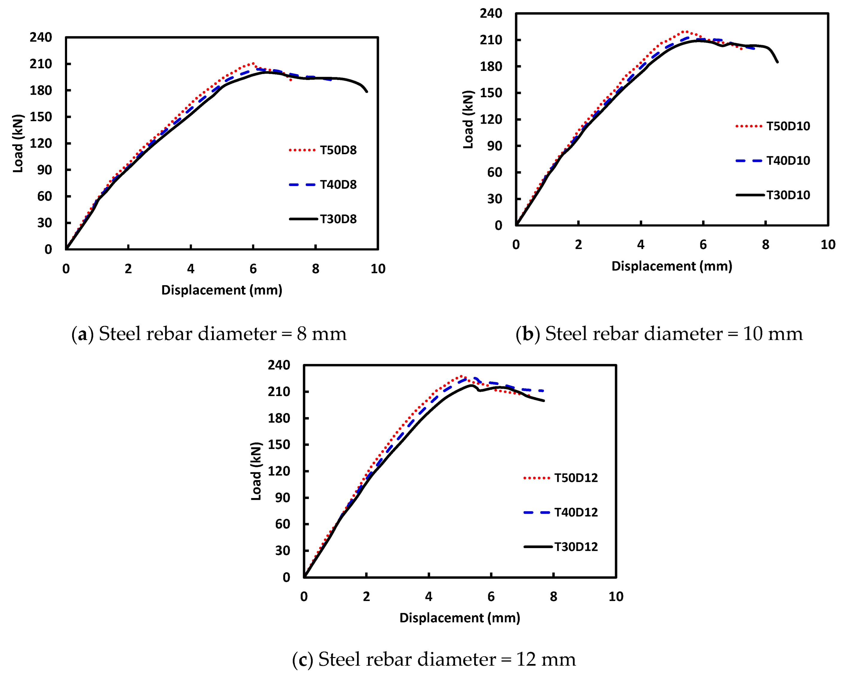
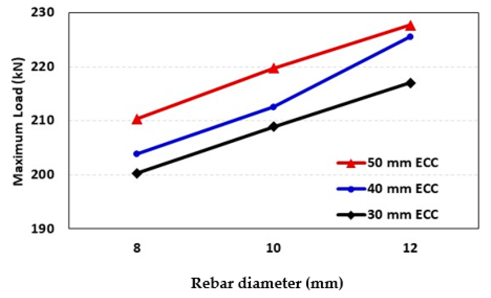
The load versus mid-span displacement responses for the analyzed beams are presented in Figure 13 and Figure 14. The increase in the ECC thickness caused a slight effect on the overall behavior of the strengthened beams. For beams having 8 mm and 10 mm steel rebars, the ECC layer thickness of 40 mm and 50 mm increased the maximum load by 1.8% and 5%, respectively, compared with the beams with 30 mm thickness. However, the observed increase in the maximum load was about 4% and 6.5% when the thickness increased to 40 mm and 50 mm, respectively, in the case of the 12 mm steel rebars. Regardless of the ECC layer thickness, increasing the steel rebar diameter from 10 mm to 12 mm enhanced the maximum load by an average value of 4.3% and 9%, respectively, compared with the 8 mm diameter as illustrated in Figure 15.

6. Conclusions

In this research, the effect of using the ECC layers on the flexural performance of RC beams previously strengthened with EB CFRP laminates was investigated. The key parameters of the experimental investigation were the existence of an additional ECC layer, CFRP width, CFRP overlap length, and CFRP overlap position. Moreover, 3D FEMs were developed using ABAQUS software and verified against the experimental results. The verified models were used to conduct a parametric study to consider the effect of the ECC layer thickness and reinforcement ratio. The main conclusions are as follows:
  • Strengthening RC beams with CFRP laminates enhanced both the stiffness and flexural capacity of beams. The flexural capacities were enhanced by 75% and 94% for the CFRP widths of 50 mm and 100 mm, respectively.
  • Providing an ECC layer to the RC beams previously strengthened with CFRP laminates exhibited additional enhancement in the flexural capacity. The improvements in the flexural capacities were 102% and 125% for the CFRP widths of 50 mm and 100 mm, respectively, compared with the control beam.
  • The employed ECC layer alongside the CFRP laminate resulted in an average increase in stiffness of about 318% when compared with the non-strengthened specimen and 149% when compared with the one strengthened with CFRP only.
  • The effectiveness of the ECC thickness on the overall behavior of the strengthened beams was affected by the steel reinforcement ratio. For the beams with 8 mm and 10 mm steel rebar diameters, the peak loads increased by 1.8% and 5% when the ECC layer thickness increased from 30 mm to 40 mm and 50 mm, respectively. However, the improvements were 4% and 6.5%, respectively, in the case of the 12 mm steel rebar diameter.
  • Regardless of the ECC layer thickness, increasing the steel rebar diameter from 8 mm to 10 mm and 12 mm enhanced the peak loads by 4.3% and 9%, respectively.

Author Contributions

Conceptualization, M.E. and M.H.; methodology, M.F.; software, M.E. and M.F.; validation, M.E. and M.F.; formal analysis, A.E.-Z.; investigation, M.E. and M.F..; resources, M.F. and A.E.-Z.; data curation, A.E.-Z. and M.H.; writing—original draft preparation, M.E., M.F. and M.H.; writing—review and editing, A.E.-Z.; visualization, A.E.-Z.; supervision, M.E. and M.H. All authors have read and agreed to the published version of the manuscript.

Funding

This research received no external funding.

Institutional Review Board Statement

Not applicable.

Informed Consent Statement

Not applicable.

Data Availability Statement

Not applicable.

Conflicts of Interest

The authors declare no conflict of interest.

References

  1. De Lorenzis, L.; Teng, J.G. Near-surface mounted FRP reinforcement: An emerging technique for strengthening structures. Compos. Part B Eng. 2007, 38, 119–143. [Google Scholar] [CrossRef]
  2. Giese, A.C.H.; Giese, D.N.; Dutra, V.F.P.; Da Silva Filho, L.C.P. Flexural behavior of reinforced concrete beams strengthened with textile reinforced mortar. J. Build. Eng. 2021, 33, 101873. [Google Scholar] [CrossRef]
  3. El-Sherif, H.E.; Wakjira, T.G.; Ebead, U. Flexural strengthening of reinforced concrete beams using hybrid near-surface embedded/externally bonded fabric-reinforced cementitious matrix. Constr. Build. Mater. 2020, 238, 117748. [Google Scholar] [CrossRef]
  4. Yuan, F.; Chen, M.; Pan, J. Flexural strengthening of reinforced concrete beams with high-strength steel wire and engineered cementitious composites. Constr. Build. Mater. 2020, 254, 119284. [Google Scholar] [CrossRef]
  5. Alharthi, Y.M.; Emara, M.; Elamary, A.S.; Sharaky, I.A. Flexural response and load capacity of reinforced concrete beams strengthened with reinforced mortar layer. Eng. Struct. 2021, 245, 112884. [Google Scholar] [CrossRef]
  6. Fawzy, K.; Hassan, H.; Madqour, M. Experimental and analytical investigations of reinforced concrete beams strengthened by different CFRP sheet schemes. Frat. Integrità Strutt. 2021, 15, 123–136. [Google Scholar] [CrossRef]
  7. Adel, B.; Noureddine, F.; Mohcene, B.; Mesbah, H.A. Modeling of CFRP strengthened RC beams using the SNSM technique, proposed as an alternative to NSM and EBR techniques. Frat. Integrità Strutt. 2020, 14, 21–35. [Google Scholar] [CrossRef]
  8. Maheswaran, J.; Chellapandian, M.; Arunachelam, N. Retrofitting of severely damaged reinforced concrete members using fiber reinforced polymers: A comprehensive review. Structures 2022, 38, 1257–1276. [Google Scholar] [CrossRef]
  9. Al-Mahmoud, F.; Castel, A.; François, R.; Tourneur, C. Strengthening of RC members with near-surface mounted CFRP rods. Compos. Struct. 2009, 91, 138–147. [Google Scholar] [CrossRef]
  10. Garg, N.; Shrivastava, S. Environmental and Economic Comparison of FRP Reinforcements and Steel Reinforcements in Concrete Beams Based on Design Strength Parameter; Malaviya National Institute of Technology (MNIT): Jaipur, India; India & Govt. Engineering College: Bikaner, India, 2019. [Google Scholar]
  11. Larrinaga, P.; Garmendia, L.; Chastre, C.; San-José, J.T. Low-grade RC beams strengthened with TRM composite based on basalt, carbon and steel textiles: Experimental and analytical study. Case Stud. Constr. Mater. 2022, 16, e00906. [Google Scholar] [CrossRef]
  12. Triantafillou, T.C.; Papanicolaou, C.G. Shear strengthening of reinforced concrete members with textile reinforced mortar (TRM) jackets. Mater. Struct. Constr. 2006, 39, 93–103. [Google Scholar] [CrossRef]
  13. Bournas, D.A.; Lontou, P.V. Papanicolaou CG, Triantafillou TC. Textile-Reinforced Mortar versus Fiber-Reinforced Polymer Confinement in Reinforced Concrete Columns. ACI Struct. J. 2007, 104, 740. [Google Scholar] [CrossRef]
  14. Emara, M.; Torres, L.; Baena, M.; Barris, C.; Cahís, X. Bond response of NSM CFRP strips in concrete under sustained loading and different temperature and humidity conditions. Compos. Struct. 2018, 192, 1–7. [Google Scholar] [CrossRef]
  15. Coelho, M.R.F.; Sena-Cruz, J.M.; Neves, L.A.C. A review on the bond behavior of FRP NSM systems in concrete. Constr. Build. Mater. 2015, 93, 1157–1169. [Google Scholar] [CrossRef] [Green Version]
  16. Al-Saadi, N.T.K.; Mohammed, A.; Al-Mahaidi, R.; Sanjayan, J. A state-of-the-art review: Near-surface mounted FRP composites for reinforced concrete structures. Constr. Build. Mater. 2019, 209, 748–769. [Google Scholar] [CrossRef]
  17. Bilotta, A.; Ceroni, F.; Nigro, E.; Pecce, M. Efficiency of CFRP NSM strips and EBR plates for flexural strengthening of RC beams and loading pattern influence. Compos. Struct. 2015, 124, 163–175. [Google Scholar] [CrossRef]
  18. Panahi, M.; Zareei, S.A.; Izadi, A. Flexural strengthening of reinforced concrete beams through externally bonded FRP sheets and near surface mounted FRP bars. Case Stud. Constr. Mater. 2021, 15, e00601. [Google Scholar] [CrossRef]
  19. Bilotta, A.; Ceroni, F.; Di Ludovico, M.; Nigro, E.; Pecce, M.; Manfredi, G. Bond Efficiency of EBR and NSM FRP Systems for Strengthening Concrete Members. J. Compos. Constr. 2011, 15, 757–772. [Google Scholar] [CrossRef]
  20. Raoof, M.; El-Rimawi, J.A.; Hassanen, M.A.H. Theoretical and experimental study on externally plated R.C. beams. Eng. Struct. 2000, 22, 85–101. [Google Scholar] [CrossRef]
  21. Barnes, R.A.; Mays, G.C. Strengthening of reinforced concrete beams in shear by the use of externally bonded steel plates: Part 1—Experimental programme. Constr. Build. Mater. 2006, 20, 396–402. [Google Scholar] [CrossRef]
  22. Smith, S.; Teng, J. FRP-strengthened RC beams. II: Assessment of debonding strength models. Eng. Struct. 2002, 24, 397–417. [Google Scholar] [CrossRef]
  23. Teng, J.G.; Yao, J. Plate end debonding in FRP-plated RC beams-II: Strength model. Eng. Struct. 2007, 29, 2472–2486. [Google Scholar] [CrossRef]
  24. Al-Obaidi, S.; Saeed, Y.M.; Rad, F.N. Flexural strengthening of reinforced concrete beams with NSM-CFRP bars using mechanical interlocking. J. Build. Eng. 2020, 31, 101422. [Google Scholar] [CrossRef]
  25. Sharaky, I.A.; Baena, M.; Barris, C.; Sallam, H.E.M.; Torres, L. Effect of axial stiffness of NSM FRP reinforcement and concrete cover confinement on flexural behaviour of strengthened RC beams: Experimental and numerical study. Eng. Struct. 2018, 173, 987–1001. [Google Scholar] [CrossRef]
  26. Sharaky, I.A.; Torres, L.; Comas, J.; Barris, C. Flexural response of reinforced concrete (RC) beams strengthened with near surface mounted (NSM) fibre reinforced polymer (FRP) bars. Compos. Struct. 2014, 109, 8–22. [Google Scholar] [CrossRef]
  27. Leung, C.K.Y. FRP debonding from a concrete substrate: Some recent findings against conventional belief. Cem. Concr. Compos. 2006, 28, 742–748. [Google Scholar] [CrossRef]
  28. Zhou, A.; Qin, R.; Feo, L.; Penna, R.; Lau, D. Investigation on interfacial defect criticality of FRP-bonded concrete beams. Compos. Part B Eng. 2017, 113, 80–90. [Google Scholar] [CrossRef]
  29. Raoof, S.M.; Koutas, L.N.; Bournas, D.A. Textile-reinforced mortar (TRM) versus fibre-reinforced polymers (FRP) in flexural strengthening of RC beams. Constr. Build. Mater. 2017, 151, 279–291. [Google Scholar] [CrossRef]
  30. Koutas, L.N.; Tetta, Z.; Bournas, D.A.; Triantafillou, T.C. Strengthening of Concrete Structures with Textile Reinforced Mortars: State-of-the-Art Review. J. Compos. Constr. 2019, 23, 03118001. [Google Scholar] [CrossRef]
  31. Vieira, A.D.A.; Triantafyllou, S.P.; Bournas, D.A. Strengthening of RC frame subassemblies against progressive collapse using TRM and NSM reinforcement. Eng. Struct. 2020, 207, 110002. [Google Scholar] [CrossRef]
  32. Al-Salloum, Y.; Siddiqui, N.A.; Elsanadedy, H.M.; Abadel, A.A. Textile-reinforced mortar versus FRP as strengthening material for seismically deficient RC beam-column joints. J. Compos. Constr. 2011, 15, 920–933. [Google Scholar] [CrossRef]
  33. Elsanadedy, H.M.; Almusallam, T.H.; Alsayed, S.H.; Al-Salloum, Y.A. Flexural strengthening of RC beams using textile reinforced mortar—Experimental and numerical study. Compos. Struct. 2013, 97, 40–55. [Google Scholar] [CrossRef]
  34. Zhang, D.; Ueda, T.; Furuuchi, H. Concrete cover separation failure of overlay-strengthened reinforced concrete beams. Constr. Build. Mater. 2012, 26, 735–745. [Google Scholar] [CrossRef]
  35. Safdar, M.; Matsumoto, T.; Kakuma, K. Flexural behavior of reinforced concrete beams repaired with ultra-high performance fiber reinforced concrete (UHPFRC). Compos. Struct. 2016, 157, 448–460. [Google Scholar] [CrossRef]
  36. Yin, H.; Teo, W.; Shirai, K. Experimental investigation on the behaviour of reinforced concrete slabs strengthened with ultra-high performance concrete. Constr. Build. Mater. 2017, 155, 463–474. [Google Scholar] [CrossRef]
  37. Prem, P.R.; Murthy, A.R. Acoustic emission and flexural behaviour of RC beams strengthened with UHPC overlay. Constr. Build. Mater. 2016, 123, 481–492. [Google Scholar] [CrossRef]
  38. Al-osta, M.A.; Isa, M.N.; Baluch, M.H.; Rahman, M.K. Flexural behavior of reinforced concrete beams strengthened with ultra-high performance fiber reinforced concrete. Constr. Build. Mater. 2017, 134, 279–296. [Google Scholar] [CrossRef]
  39. Deng, M.; Ma, F.; Ye, W.; Li, F. Flexural behavior of reinforced concrete beams strengthened by HDC and RPC. Constr. Build. Mater. 2018, 188, 995–1006. [Google Scholar] [CrossRef]
  40. Deng, M.; Zhang, M.; Ma, F.; Li, F.; Sun, H. Flexural strengthening of over-reinforced concrete beams with highly ductile fiber-reinforced concrete layer. Eng. Struct. 2021, 231, 111725. [Google Scholar] [CrossRef]
  41. Li, V.C.; Wang, S.; Wu, C. Tensile strain-hardening behavior or polyvinyl alcohol engineered cementitious composite (PVA-ECC). ACI Mater. J. 2001, 98, 483–492. [Google Scholar] [CrossRef]
  42. Zhang, J.; Leung, C.K.Y.; Gao, Y. Simulation of crack propagation of fiber reinforced cementitious composite under direct tension. Eng. Fract. Mech. 2011, 78, 2439–2454. [Google Scholar] [CrossRef]
  43. Yang, X.; Gao, W.Y.; Dai, J.G.; Lu, Z.D.; Yu, K.Q. Flexural strengthening of RC beams with CFRP grid-reinforced ECC matrix. Compos. Struct. 2018, 189, 9–26. [Google Scholar] [CrossRef]
  44. Hamoda, A.; Abdelazeem, F.; Emara, M. Concentric compressive behavior of hybrid concrete–Stainless Steel Double-Skin Tubular Columns incorporating High Performance Concretes. Thin-Walled Struct. 2020, 159, 107297. [Google Scholar] [CrossRef]
  45. Zhou, J.; Pan, J.; Leung, C.K.Y. Mechanical behavior of fiber-reinforced engineered cementitious composites in uniaxial compression. J. Mater. Civ. Eng. 2015, 27, 04014111. [Google Scholar] [CrossRef]
  46. Chen, Y.; Yu, J.; Leung, C.K.Y. Use of high strength Strain-Hardening Cementitious Composites for flexural repair of concrete structures with significant steel corrosion. Constr. Build. Mater. 2018, 167, 325–337. [Google Scholar] [CrossRef]
  47. Awad, F.; Husain, M.; Fawzy, K. Flexural behaviour of reinforced concrete beams strengthened by NSM technique using ECC. Frat. Integrità Strutt. 2022, 16, 291–309. [Google Scholar] [CrossRef]
  48. Zhou, Y.; Sui, L.; Huang, X.; Guo, M.; Luo, M.; Hu, B.; Cheng, C. Enhancing the EB-FRP strengthening effectiveness by incorporating a cracking-control layer of ECC with different thicknesses. Constr. Build. Mater. 2021, 286, 122975. [Google Scholar] [CrossRef]
  49. Hu, B.; Zhou, Y.; Xing, F.; Sui, L.; Luo, M. Experimental and theoretical investigation on the hybrid CFRP-ECC flexural strengthening of RC beams with corroded longitudinal reinforcement. Eng. Struct. 2019, 200, 109717. [Google Scholar] [CrossRef]
  50. Li, Z.Q.; Hou, W.; Lin, G. Flexural strengthening of RC beams with BFRP or high strength steel bar–reinforced ECC matrix. Constr. Build. Mater. 2021, 303, 124404. [Google Scholar] [CrossRef]
  51. ECP-203 Egyptian Code for Design and Construction of Reinforced Concrete Structures; National Housing and Building Research Center: Cairo, Egypt, 2018.
  52. Mahmood, E.M.; Allawi, A.A.; El-Zohairy, A. Analysis and Residual Behavior of Encased Pultruded GFRP I-Beam under Fire Loading. Sustainability 2022, 14, 13337. [Google Scholar] [CrossRef]
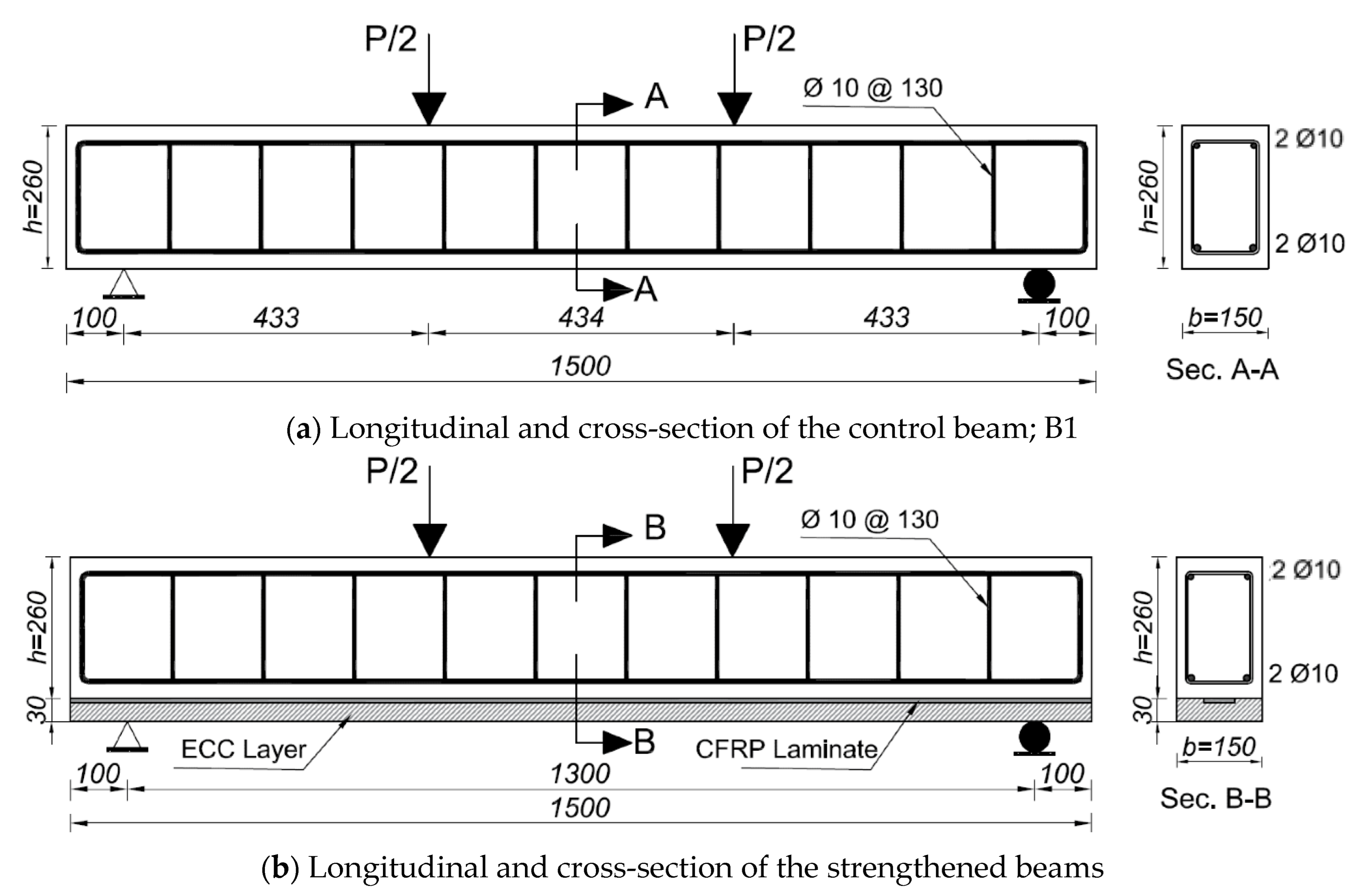
Figure 1. Schematic of the tested beams (units shown are in mm).
Sustainability 14 16990 g001aSustainability 14 16990 g001b
Figure 2. Fibers used in the ECC.
Sustainability 14 16990 g002
Figure 3. The tensile and compressive stress-strain relationships of ECC specimens.
Sustainability 14 16990 g003
Figure 4. Casting and strengthening of the tested beams.
Sustainability 14 16990 g004aSustainability 14 16990 g004b
Figure 5. Test setup and instrumentations.
Sustainability 14 16990 g005
Figure 6. Definition of main points on the load-deflection relationship.
Sustainability 14 16990 g006
Figure 7. Load–displacement curves of the tested beams.
Sustainability 14 16990 g007
Figure 8. Load–axial strain curves of the steel rebars.
Sustainability 14 16990 g008
Figure 9. Crack patterns and failure modes of the tested beams.
Sustainability 14 16990 g009aSustainability 14 16990 g009bSustainability 14 16990 g009c
Figure 10. Finite element mesh and elements.
Sustainability 14 16990 g010
Figure 11. Comparisons of the load-displacement curves for the experiments and FEMs.
Sustainability 14 16990 g011
Figure 12. Crack pattern comparisons between the experiments and FEMs.
Sustainability 14 16990 g012
Figure 13. Effect of the ECC thickness.
Sustainability 14 16990 g013
Figure 14. Effect of the steel rebar diameter.
Sustainability 14 16990 g014
Figure 15. Effects of the ECC thickness and steel rebar diameter on the ultimate capacities of the strengthened beam.
Sustainability 14 16990 g015
Table 1. Characteristics of the tested beams.
Beam IDCFRP Width (mm)CFRP Overlap Length (mm)ECC LayerRemarks
B1---------Control beam
B2100------1 CFRP strip without ECC layer
B3100---1 CFRP strip + ECC layer
B4100100100 mm overlapped CFRP strips + ECC layer
B5100200200 mm overlapped CFRP strips + ECC layer
B6100300300 mm overlapped CFRP strips + ECC layer
B7100200 tip-to-tip2 CFRP layers connected tip-to-tip + ECC layer
B850------1 CFRP strip without ECC layer
B950---1 CFRP strip + ECC layer
B1050100100 mm overlapped CFRP strips + ECC layer
B1150100100 mm overlapped CFRP strips (at the third of beam span) + ECC layer
Table 2. Mix proportions and compressive strength of the NC and ECC.
ConcreteCement Fine AggregateCoarse AggregateFly AshWater/BinderPP *PVA *HRWR *fc
(kg/m3)(kg/m3)(kg/m3)(kg/m3) (kg/m3)(kg/m3)(kg/m3)(MPa)
NC3507001150---0.43---------28
ECC600480 **---7200.2519.82612.549
* PP: polypropylene fibers; PVA: polyvinyl alcohol (PVA) fiber; HRWR: high-range water reducer. ** Silica sand.
Table 3. Properties of the PVA and PP fibers.
DiameterLengthSpecific GravityElastic ModulusTensile StrengthElongation at Breakage
(μm)(mm)(g/cm3)(GPa)(MPa)(%)
PVA20151.33713007
PP18180.915.455030
Table 4. Experimental test results.
BeamCrackingYieldUltimate Failure Mode
PcrPcr(Bi)crPyPy(Bi)yPuPu(Bi)uK
(kN)Pcr(B1)(mm)(kN)Py(B1)(mm)(kN)Pu(B1)(mm)(kN/mm)
B121.091.000.8164.291.005.2978.141.0011.0526.03F + CC
B226.341.190.57126.801.974.96151.971.946.7146.21S + ED
B336.871.630.42136.672.134.97176.092.256.7287.78S + EP
B435.191.590.39169.502.645.59191.412.456.5190.23S
B536.081.630.26172.672.674.59217.052.786.30138.76S
B636.251.640.18181.482.824.14212.292.725.62201.38F + ICD
B736.581.660.38194.333.026.08201.182.577.2296.26S + EP
B824.561.110.55105.721.644.65136.901.757.2244.65S + CCS
B936.041.670.45138.512.155.23157.732.027.3680.09S + CCS
B1036.321.640.42158.622.474.97180.612.316.1786.47S + F
B1136.331.640.51156.212.436.89162.872.087.8671.23S + F
Pcr = Cracking load, ∆c = Displacement at cracking load, Py = Yielding load, ∆y = Displacement at yielding load, Pu = Ultimate load, ∆u = Displacement at ultimate load, K = Stiffness, F = Flexural failure, CC = Concrete Crushing of the compression zone, S = Shear failure, ED = End Debonding, EP = End Peeling, ICD = Intermediate Crack Debonding, and CCS = Concrete Cover Separation.
Table 5. Summary of the investigated parameters.
Beam IDECC Layer Thickness (mm)Steel Rebar Diameter (mm)Number of Steel Rebars
T30D030--------
T30D83082
T30D1030102
T30D1230122
T40D84082
T40D1040102
T40D1240122
T50D85082
T50D1050102
T50D1250122
Publisher’s Note: MDPI stays neutral with regard to jurisdictional claims in published maps and institutional affiliations.