Article

Effect of Embedded Basement Stories on Seismic Response of Low-Rise Building Frames Considering SSI via Small Shaking Table Tests

by
Mohammed El Hoseny
1,2,*,
Jianxun Ma
1,* and
Musanyufu Josephine
1
1
School of Human Settlements and Civil Engineering, Xi’an Jiaotong University, Xi’an 710054, China
2
Department of Civil Engineering, Faculty of Engineering at Shoubra, Benha University, Cairo 11629, Egypt
*
Authors to whom correspondence should be addressed.
Sustainability 2022, 14(3), 1275; https://doi.org/10.3390/su14031275
Submission received: 10 December 2021 / Revised: 6 January 2022 / Accepted: 18 January 2022 / Published: 24 January 2022

Abstract

:
The dynamic soil-structure interaction is a combination of phenomena caused by the flexibility of soil foundation in structure response. The structure response may be changed by embedded basement stories. Thus, this study seeks to assess the dynamic response of seven-story concrete frame type buildings without a basement, one basement story, and two basement stories, considering fixed and flexible bases. For this purpose, the experimental tests on the small shaking table were executed with a small scaling coefficient of 1:50. Consequently, three scaled models of steel skeleton structures with variable embedded depths have been constructed with fixed and flexible bases. These models are exposed to three seismic input motions: Northridge (1994), Kobe (1995), and Chi-Chi (1999) at the base of the structure as a fixed base and the bedrock level in the soil structure system as a flexible base. The finite element technique is carried out for scaled and real models. Both the scaled and real numerical models are in good agreement with the obtained experimental observations with reasonable accuracy. It is concluded that the lateral deflections are overestimated by excluding embedded depths of structural elements. In the flexible prototype model, the lateral deflections of the superstructure with embedded depths (3 m, 6 m) decrease compared with no embedded depth, in which the maximum reduction percentages of 7-story with embedded depths 3 m and 6 m at the roof floor level are 21% and 42% compared with no embedded depth, respectively, under Northridge earthquake. Otherwise, ignoring the SSI effects (fixed base case), the lateral displacements are underestimated compared with the flexible base. The maximum amplification percentages at the roof floor level between flexible and fixed bases models with variable embedded depths are 35%, 37%, and 65% under Northridge, Kobe, and Chi-Chi earthquakes, respectively. The amplification and reduction percentages may be high or low, mainly depending on soil condition (fixed, flexible), variable embedded depths, characteristics of seismic motion, travel pass, and source of seismic motion. These items are summarized as the frequency domain of the coupled system compared with the frequency domain of the earthquake motion.

1. Introduction

The effects of dynamic soil-structure interaction are sometimes ignored during seismic analysis. However, in reality, the system of soil-foundation is detrimental to structural behavior. In addition, numerous reports of damaged structures due to earthquakes presented that the Soil-Structure Interaction (SSI) has influenced structures’ seismic vulnerability. Therefore, the soil-structure interaction problem becomes substantial, especially in active seismic regions. The Soil-Structure Interaction (SSI) can be summarized as inertial and kinematic interactions. Both inertial and kinematic interactions generally affect the foundation vibrations and can increase displacements and decrease base shear and overturning moments [1,2,3]. In addition, many design engineers consider the walls around basement stories to be only used to prevent the soil from collapsing inside the building and neglecting its effects in seismic analysis. Therefore, it is imperative to simulate the seismic response of structures considering SSI and variable embedded depths.
Several researchers have discussed the SSI effects, but fewer have addressed the effects of embedment structural elements considering SSI. Beredugo and Novak (1972) mentioned that the structural elements embedment had increased the resonant frequencies, reduced resonant amplitudes [4], and increased the radiation damping [5]. Spyrakos and Xu (2004) studied the embedment depth effects by comparing two different embedment depths of foundations (2 m and 4 m) with a surface foundation [6]. It was observed that the resonance frequencies of embedded foundations are close compared with the surface foundation. Another investigation [7] simulated the elevated fluid tank with a structural frame supported on a foundation soil system with variable embedded depths. The finite element technique was carried out by ANSYS software. The models were analyzed for the foundations with and without embedded depths. It was indicated that the lateral displacement of the roof level of the elevated tank was significantly affected with variable embedment depths, especially in soft soil. Others [8,9] studied the effect of foundation embedment under different frequencies. It was concluded that the foundation embedment decreases the roof displacements under all frequencies with different percentages. This study [10] focused on SSI analysis considering the foundation’s embedded depths of asymmetric six-story reinforced concrete space frame building supported on stiff soil and exposed to seismic loadings. It was concluded that the soil foundation structure interaction with the consideration of different embedment depths is significant in modifying the seismic response of the building. Turan et al. (2013) stated that the lateral dynamic responses of a single degree of freedom considering variable embedment depths decrease slightly in the soil-structure interaction analysis. In addition, with increasing embedment depth, the resonance frequency becomes a bit higher [11]. However, the general consensus about the increasing embedment depths is that the lateral response and period of the structures decrease because the soil stiffness (shear modulus) increases with the soil depth [7].
Many researchers have applied different approaches to study the SSI effects. For example, the analytical studies [12,13] were carried out to investigate the torsional response of embedded foundations considering the SSI effects. While Ref. [14] examined the response of the embedded footing under vertical vibration by approximate analytical solution. Moreover, Stewart et al. [15] applied analytical methods to evaluate the inertial SSI effects on seismic response of the structure by considering site conditions, foundation embedment, shape, and flexibility. While Mylonakis et al. [16] used the simplified expressions for computing the kinematic response of footings under seismic loading. Later, Kim et al. [17] improved two SSI parameters using the dynamic centrifuge tests and analytical approach.
Other studies were extended, such as in Ref. [18], the researchers used the numerical model to solve the steady-state problem of coupled rocking and horizontal vibrations of footings embedded. Moreover, Wolf and Darbre [19] based on the boundary element method in numerical analysis to conclude the dynamic stiffness matrix of the embedded foundation. In addition, Gan et al. [20] investigated numerically the seismic response of three adjacent tall buildings with pile raft foundations arranged in a viscoelastic half-space. In this study [21], they observed the seismic response of a cooling tower supported on the pile of a petrochemical facility located in Italy by 3D Finite Element Method (FEM) analysis considering the SSI effects. Ref. [22] simulated 3D structural modeling supported on shallow foundations numerically by Opensees software to investigate the complex soil-structure interaction with liquefaction. In addition, Forcellini [23] observed the SSI effects on a residential structure with base isolation by performing 3D numerical simulations with Opeensees software. While he performed a new framework to assess the SSI effects by equivalent fixed-based models and validated with nonlinear dynamic numerical simulations modeled by Opensees [24]. Ref. [25] focused on the FEM and bi-directional lumped-mass-story-stiffness numerical models to investigate the SSI effects on an instrumented 16-story building. However, most analytical and numerical studies are more than experimental observations.
The experimental studies are not commonly performed due to cost and skilled labor requirements, which Ref. [26] examined the experimental observations on a school building in Taiwan under forced vibration tests and compared the results with numerical simulations. Furthermore, Ref. [27] assessed the frequency and damping variation of low-rise masonry buildings based on experimental observations. Goktepe et al. [28] investigated the seismic response of a six-story building considering the SSI effects, while Ref. [29] examined the SSI effects of fifteen stories supported on soft soil. In addition, Lee et al. [30] assessed the boundary effects of laminar container in centrifuge shaking table test. Moreover, Ahn et al. [31] examined the shaking-table tests for single-degree of freedom and multi-degree of freedom superstructures.
The full-scale experimental observations are the better research methods for observing and understanding the seismic SSI effects on the building. Ref. [32] examined the seismic response of a 14-story reinforced concrete building as full-scale construction in Srpska under 20 recorded earthquakes. In addition, Ref. [33] applied a large-scale single degree of freedom structure supported on soft soil experimentally and compared the results with FEM results. Nevertheless, such research execution would be difficult due to complex high-technical instrumentations with skilled labor and the high costs of the experimental setup. The small capacity shaking table tests provide an alternative cost-effective research method to determine the essential characteristics of the seismic analysis of a coupled system. Therefore, to verify the computer analysis models and the environment of limited experiment conditions for instrumented model structures, it is a condition to compare the gathered data from the laboratory tests with numerical findings to verify and extend parametric studies for prototype models [34].
Several experimental tests with scaled models have been accomplished to investigate the dynamic response of buildings. The 1:45 scale model of the 6-story moment-resisting frames was executed on the shaking table by Goktepe et al. (2019) to evaluate the small scale coefficient to capture the dynamic response of structures [28]. The experimental and numerical simulations achieved reasonable accuracy. Tabatabaiefar et al. (2014) developed a scaled factor of 1:30 for a real coupled SSI system [35]. The laboratories investigations were verified with numerical results examined by FLAC2D software and obtained good results. Therefore, the developed numerical model was compatible with Laboratory measurements. In addition, the seismic behavior of four steel models rested on soft soil were evaluated as experimental tests with a scale of 1:100 that achieved good agreements with numerical results [36]. Chunyu et al. (2012) applied a series of shaking table tests with a 1:40 scale model to estimate the seismic response of the irregular tall buildings under earthquake loadings [37]. The experimental results showed that the structure could meet the Chinese code requirements. Others [38] performed a 1:30 scaled factor of an Office Building consisting of a concrete-filled steel tube frame and a steel plate reinforced concrete core wall in Beijing, China. It was concluded that the prototype structure could meet the performance-based seismic design requirements.
In the past, most researchers studied only the dynamic behavior of the soil inside the container under seismic motions [30,39,40]. Other studies [41,42] had considered the soil container with simplified structural models as a single degree of freedom. However, the simplified structural models may not be convenient to reality. Therefore, in this study, the coupled system models, including soil and superstructure, are simulated in one model to represent the real construction of buildings.
The increasing demand for low-income housing in Egypt has fostered the construction of buildings with reinforced concrete and with few stories (low-rise buildings) that necessitate the study of low-rise buildings’ behavior with variable embedded depths considering SSI effects. For addressing this issue, the objectives of this study are to (i) assess the accuracy of the small-scaled coefficient in representing the dynamic behavior of structures by verifying the experimental results with numerical simulations, (ii) evaluate the SSI effects on seismic response of low-rise buildings compared with fixed bases, and (iii) simulate the effects of basement stories on the dynamic response of the low-rise buildings whether with fixed and flexible bases.

2. Model Description

In this study, the actual prototype examined for the SSI system consists of a seven-story reinforced concrete frame-type building with variable embedded depths of structural elements. For simulating the real construction of the SSI system in the laboratory, a series of small-scale shaking table tests of the 7-story steel frame with variable embedded depths were considered. These models were laid directly on the shaking table as a fixed base and on the silty clay soil to consider SSI effects. The experimental tests were carried out on a shaking table in the construction and material laboratory, American University in Cairo (AUC), Egypt. The shaking table characteristics are: length is 1.70 m; width is 1.30 m; maximum displacement is ±75 mm, and the maximum applied load is five tones. Therefore, the appropriate geometric scaling coefficient is 1:50 for the shaking table tests due to dimension limitations and maximum loads of the shaking table. Three seismic records have been applied at the level of the shaking table. The experimental observations were compared with numerical simulations of the coupled system accomplished by PLAXIS 3D software [43]. The full details are illustrated as follows:

2.1. Real Characteristic of the Soil-Structure System

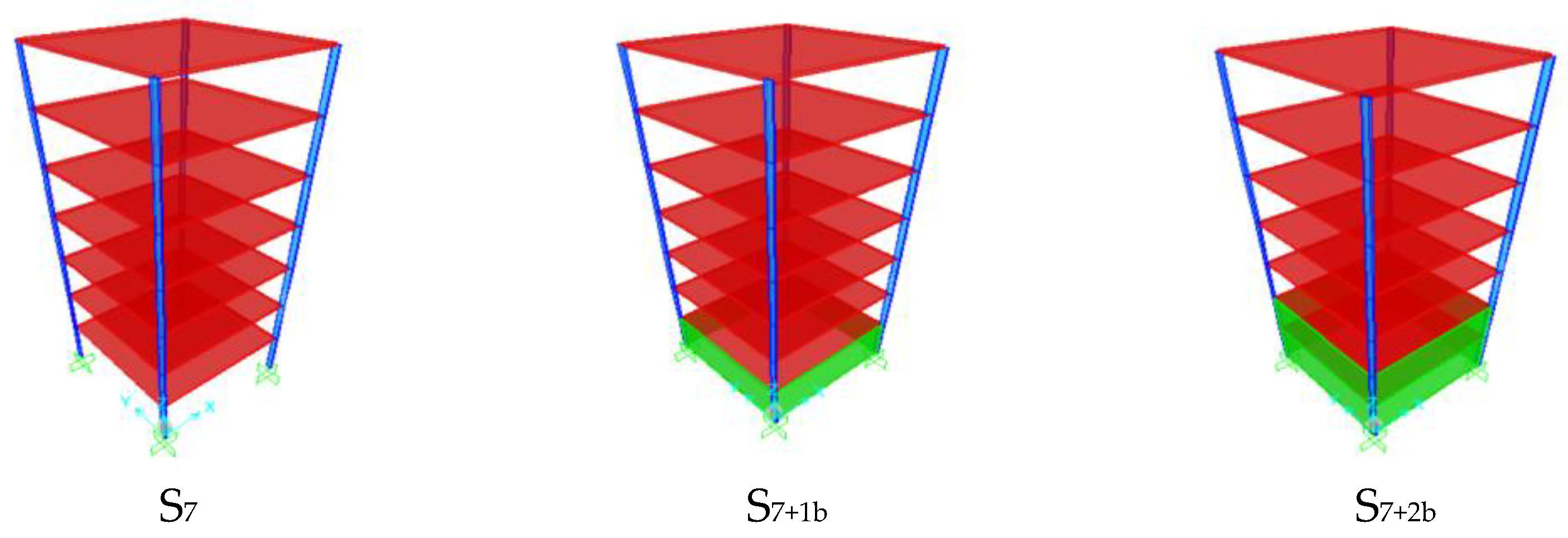
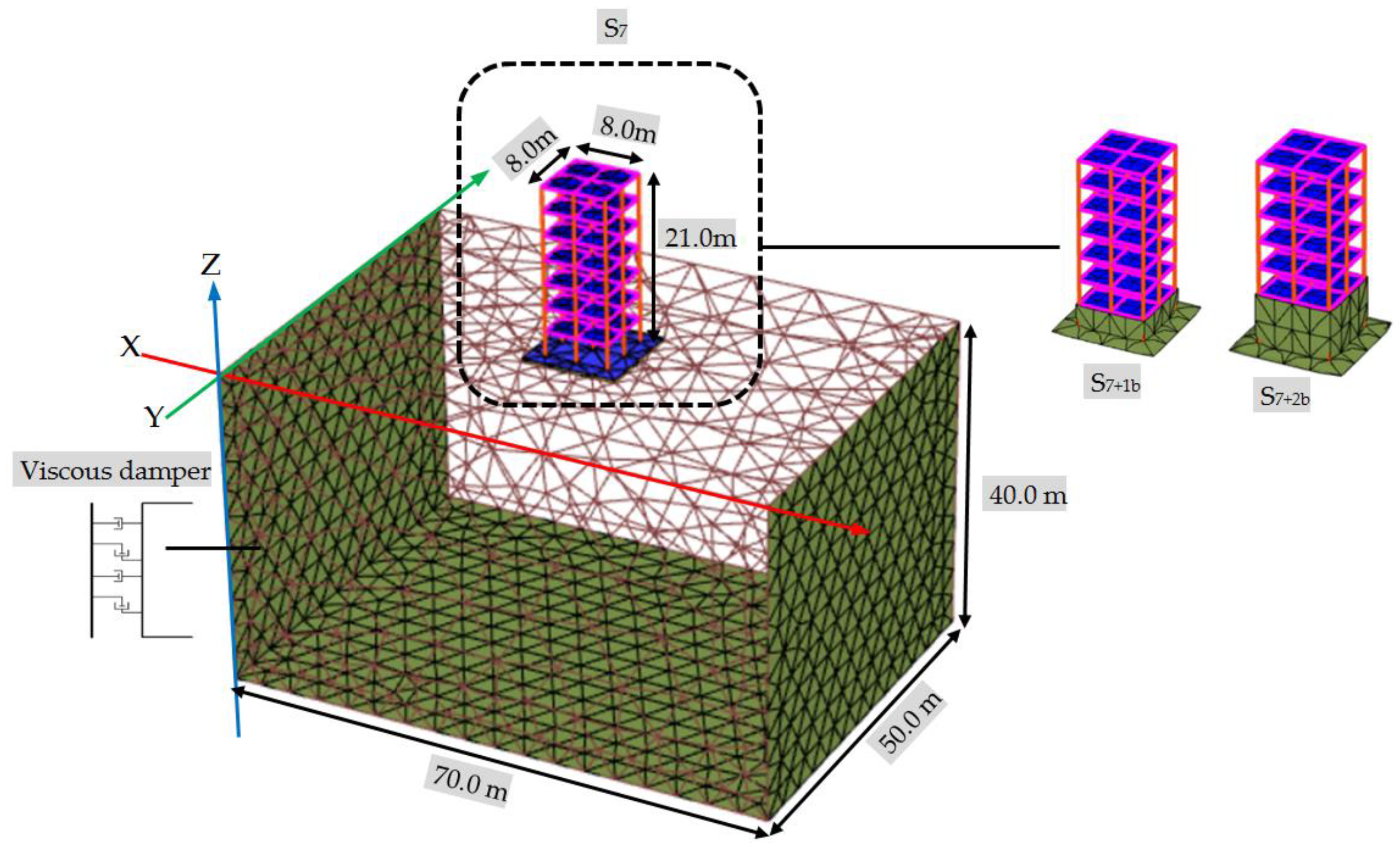
The three prototype superstructures consist of seven-story concrete frames with variable raft foundation levels (i.e., at near ground level (S7), −3 m (S7+1b), and −6 m (S7+2b) from ground level). The total height of the prototypes is 21 m. Each prototype model has double bays designed to be 8 m in and out of planes, and the bay span is 4 m. For basement stories, the prototype models have retaining walls around the building with a thickness of 250 mm. The dimensions of all columns and beams are 800 mm × 800 mm and 300 mm × 600 mm, respectively. The slab thickness is 160 mm. The mechanical properties of all elements are the same, in which the modulus of elasticity (E) is 25,742.96 MPa, and the average compressive strength (ƒc) is 30 MPa. The prototype models are supported on fixed and flexible bases. The configuration of the real models in the SSI system is shown in Figure 1. In addition, the actual dimensions of discretized soil layer over bedrock level used in the dynamic analysis are to be 70 m in length, 50 m in width, and 40 m in depth. The soil medium is silty clay with a shear wave velocity of vs. = 220 m/s and unit weight of γ = 17.8 kN/m3.
Numerical analyses were simulated on the prototype models with a fixed base by SAP 2000 software [44] to check the preliminary safety of sections and conclude the fundamental frequencies of these models. Therefore, Table 1 presents the natural frequencies and total masses of the three prototypes.

2.2. Scaling Coupled Models for Shaking Table Tests

An electric actuator can activate the shaking table with an electric servo valve and a controller, controlled by special software in the computer. In addition, Accelerometers and Linear Variable Differential Transformers (LVDTs) simulated the dynamic superstructure by connecting with dynamic data collectors. The environmental components of the shaking table tests are displayed in Figure 2.
The convenient geometric scaling coefficient is one of the fundamental steps of the experimental studies with limitations of the shaking table. Therefore, the Cauchy condition is essential to establish the series shaking table tests for dynamic analyses of the coupled system [45]. The similitude laws of geometric and dynamic between the prototype and scale models used in the shaking table test are presented in Table 2 [11,29].
According to the specifications (dimensions and max. loads) of the shaking table and similitude laws, the dimensions and weight of the scaled model are shown in Table 3. Consequently, the suitable geometric scaling factor was determined to be λ = 1:50 in this study. Thus, the total height and width in both directions of superstructures were scaled as 0.42 m and 0.16 m, respectively. Due to the fact that the models of the concrete frame were not favorable for the test conditions, equivalent steel structure models were determined according to the similitude rule. In addition, the scaled soil size domain applied in the shaking table test was selected to be 1.40 in length, 1.0 m in width, and 0.80 m in depth.
To conclude the steel skeleton section properties, the natural frequencies and total masses of the three prototypes shown in Table 1 should be scaled with a factor of λ−0.5 and λ3, respectively. Therefore, Table 4 presents the required frequencies and masses of three scaled models.
3D numerical models have been achieved through SAP2000 software as shown in Figure 3 to conclude the steel skeleton section properties by employing the required characteristics of scaled models in Table 4 and dimensions of scaled models. After several trials to adopt the required characteristics, the final dimensions of each floor plate are 160 mm × 160 mm × 3.5 mm while 7 mm × 1.5 mm × 420 mm as four vertical steel column plates. Additionally, four and eight vertical steel plates with dimensions 160 mm × 60 mm × 1.5 mm are used as retaining walls in the case of seven stories with one basement story (S7+1b) and two basements stories (S7+2b), respectively. The connection used between elements is welded, and the mild steel 240/350 is adopted. Consequently, Table 5 presents the adopted natural frequencies and total masses of three scaled models. It is observed that the maximum variations between required and adopted for natural frequencies and total masses do not exceed 2.6%. The three scaled models were assembled in the workshop, as depicted in Figure 4.

Scaling Geotechnical Model and Soil Properties

The geotechnical model cannot be directly found on the shaking table; a container is required to represent the boundary of the soil in which the soil is placed. The inner dimensions of the laminar box for homogenous soil are 1.40, 1.00, and 0.80 m, corresponding to the length, width, and depth, respectively.
Many researchers [46,47] mentioned that the laminar shear box is the most appropriate method used to describe the truncated boundaries of the soil in the dynamic analysis, with aluminum sections and rubber layers used as manufacturing materials. In addition, the essential parameter to construct the laminar box is the natural frequency. It should be close to the natural frequency of the soil medium to prevent any interaction effects between the soil and container. Therefore, the natural frequency of the scaled soil layer was calculated as 9.72 Hz [48].
Based on the previous discussion, 3D numerical models were simulated by SAP2000 software as 1D frame elements, and 2D shell elements were applied to represent the aluminum sections and rubber layers, respectively, as shown in Figure 5. After trial and error cycles to match with the required frequency of the soil layer, the natural target frequency of the laminar shear box was concluded as 9.43 Hz, which matched with the natural frequency of the soil layer [48]. As a result, the manufacturing of the laminar box was composed of ten aluminum frames with dimensions 80 mm × 40 mm × 2 mm and nine rubber layers with dimensions 40 mm × 50 mm.
The aluminum frames and rubber layers were joined by high-strength resin. Afterward, the interior container was covered with 20 mm thick foam sheets for truncated sides to reduce the reflected waves in the free field conditions [35,49]. In addition, plastic sheeting was added to prevent the water in the soil from evaporation. A wooden base plate connected both the shaking table and the first aluminum frame to prevent the soil from being placed on the shaking table directly. Finally, the soil particles were resin at the bottom of the container to represent the frictional surface between the bedrock and the soil, as displayed in Figure 5.
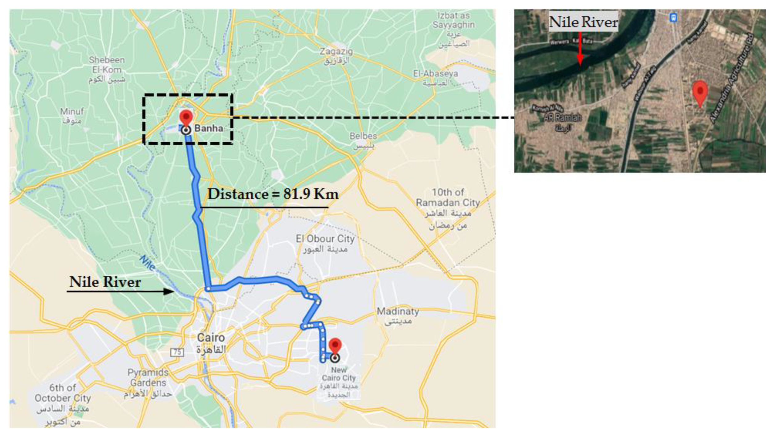
Most of the population in Egypt is concentrated around the Nile River, of which the common type of soil may be clayey to loamy in texture. Representative soil block was taken from a site located in Banha city, Qalyubia, Egypt, as shown in Figure 6 to represent the real condition of the coupled system. Samples of the soil block were examined in the soil mechanics laboratory at the AUC. It was found that the structure of this soil is mainly 70% clay and 30% silty. Table 6 summarizes the soil layer characteristics examined in the soil laboratory. During the transportation of the soil block to the laboratory (a distance of more than 80 km), the soil moisture content decreased.
In order to place the soil in the laminar box, the box was divided into 16 layers by laser lines; each layer of soil was remolded with specific water quantities in the determined layer and compacted with a free hammer to get the same characteristics as in Table 6. Many specimens were provided to ensure the mechanical properties of the underlying soil in the laminar box. It is noted that the soil properties used in the laminar shear box are accepted with the field specimens as in Table 6. A rectangular hole of 60 mm and 120 mm depths were excavated to locate the scaled models with one basement and two basements, respectively, ensuring no gaps around sidewalls.

2.3. Displacement Time Histories Records

Seismic analyses of the prototype and scaled models were tested under three different seismic loadings: Northridge (Mw = 6.7 in 1994), Kobe (Mw = 6.9 in 1995), and Chi-Chi (Mw = 7.6 in 1999) records. To conclude the three scaled seismic records, the displacement and time step values were scaled by a coefficient of λ = 0.02 and λ0.5 = 0.14142, respectively, according to the similitude rule in Table 2. Figure 7 shows the displacement time histories for studied earthquakes as original records for prototype models and scaled records for scaled models. In addition, the properties of the original earthquakes are reported in Table 7. The seismic earthquakes records have been carried out at the fixed base and the bedrock level (a flexible base).
The dynamic electric actuator can measure the output displacement at the direction of movement to ensure the consistency of the obtained records of the input motions. Consequently, the average dynamic actuator records (Avg. Dyn. Act.) are displayed in Figure 7b, which agree with the different scaled input motions.

3. Experimental Measurements

3.1. Shaking Table Tests without SSI Effects (a Fixed Base)

Three scaled superstructures were secured and fixed on the shaking table to determine the natural frequencies and lateral seismic response. Therefore, instrumentations including LVDTs and accelerometer were set up on each structure. Three LVDTs were installed as two LVDTs at the shaking table level and one LVDT at the roof level. In addition, one accelerometer was fixed on the roof floor level to verify the LVDT reading values by double integration for acceleration values readings. The installation of LVDTs and accelerometer are displayed in Figure 8.
A sine sweep test was applied to three scaled models before observing the seismic behavior of scaled models in the case of a fixed base. The frequency of the shaking table has increased from 1 Hz to 20 Hz. The first resonance between the scaled model and the shaking table displayed the fundamental natural frequency of each model. The test was repeated to an adequate accuracy. The natural frequencies of three constructed models obtained from the sine sweep test were 11.5, 13.5, and 16.0 Hz for S7, S7+1b, and S7+2b models, respectively. These agreed with the required and target frequencies in both Table 4 and Table 5. The maximum variations between experimental and numerical analyses (required or target frequencies) for three scaled models are less than 4.0%, achieving adequate accuracy.
After ensuring the dynamic characteristics of the three scaled structural models, three scaled seismic records of Northridge (1994), Kobe (1995), and Chi-Chi (1999) were applied at the base of structural models. The obtained values from the experimental measurements are related to absolute displacement. This includes the movement of the shaking table and the relative displacement of the structural model.

3.2. Shaking Table Tests with SSI Effects (a Flexible Base)

The laminar shear box was fixed on the shaking table by a hardwood plate. After that, the soil was placed into the box. After filling the laminar box in one day, the surface was sealed and covered by a plastic sheet to maintain the water content, and the soil became homogenous. On the second day, the structural models were lifted and placed on the determined location. For structural models with basements, the filling soil around retaining walls was executed by the same soil and compaction to maintain the homogenous soil mix. Accelerometer and LVDTs were set up as similar to fixed base cases. Figure 9 displays the final setup of the seven stories without a basement (S7) as an example of the SSI system. Shaking table tests were excited by three scaled seismic motions at the shaking table level. Therefore, the obtained results are also in the term of absolute lateral displacements, including the transition component of the shaking table, rocking component from foundation rotation, and elastic-plastic relative movement of the superstructure.

4. Numerical Simulations

4.1. Finite Element Analyses of Prototype and Scaled Models without SSI Effects (Fixed Base)

The main goal of the numerical analyses is to verify the results with experimental observations to extend parametric studies in actual cases. Therefore, the numerical prototype and scaled models of the fixed bases were carried out by SAP2000 software based on the finite element method as mentioned above. After ensuring the fundamental frequencies agreed with experimental results, fully nonlinear time histories were applied at the base of the structures under three seismic motions. The maximum absolute lateral displacements of the roof floor level under three seismic motions for prototype and scaled models are concluded.

4.2. Finite Element Analyses of Prototype and Scaled Models with SSI Effects (Flexible Base)

The effects of the SSI system on seismic response were simulated numerically under three seismic scenarios. In order to evaluate these effects, the finite element models were built by the PLAXIS 3D software. The direct method was developed to simulate the soil-structure system problem. Many researchers mentioned that the linear elastic- perfectly plastic under Mohr-coulomb criteria failure represents the constitutive soil model in dynamic analyses and achieved good results [2,28,35]. According to Mohr-Coulomb (MC) criterion, the normal and shear stresses are generated at Gauss points and then compared with the Mohr-Coulomb failure criterion. The Friction angle (Φ), Cohesion (C), and the Dilatancy angle (Ψ) are used to describe the irreversible change in volume during seismic forces. Fully nonlinear dynamic analyses were applied under three earthquake records adopted at the bedrock level.
The appropriate boundary conditions simulate the far-field behavior of the soil medium by absorbing the increment of stresses and voiding any reflecting waves. Therefore, Free field boundaries and interface elements were recommended in the seismic analysis [43]. The free field boundaries with viscous dampers were employed for infinite soil medium to minimize the reflecting waves and simulate the energy losses. The normal and shear stresses at the boundaries depending on the pressure and shear wave velocities are described by Lysmer and Kuhlmeyer (1969) [51] as follow:
σ x , y = C 1 ρ V p u ˙ x , y
τ = C 2 ρ V s u ˙ z
where σx,y is the normal stresses in the x or y direction, respectively, τ is the shear stress in zx or zy planes, ρ is the density of the soil material, Vp and Vs are pressure and shear wave velocities, respectively, u ˙ x and u ˙ y are the nodal velocities at the boundaries in x and y directions, respectively, and C1 & C2 are the relaxation coefficients were used to develop the absorbent boundaries at the calculation stages. Therefore, several trials were examined to adopt the best values of the relaxation coefficients to improve the absorption effects. The best values of records C1 & C2 are based on measuring output vs. input records at the bedrock level, which are 1.00 and 0.67, respectively. The compliant base was considered at the bottom of the soil medium to represent the bedrock level. The compliant base is combined between the viscous boundaries to absorb any reflecting waves and surface prescribed displacement to apply the earthquake records. Moreover, the surface prescribed displacements were u ˙ x = 0.001 m (which the unit of displacement earthquake records is mm), u ˙ y = 0, and u ˙ z = 0 at the compliant base to multiple these factors with seismic record values.
The slab element and column element were represented as plate and beam elements, respectively. To achieve the desired accuracy of dynamic analyses of the SSI system with appropriate time, the mesh sensitively is essential to ensure transmitting seismic waves in the finite element models. Therefore, the mesh size should not exceed one-eighth to one-fifth of the shortest wavelength at the highest frequency of the significant components of the input motions [52]. Therefore, the mesh size in the seismic analyses for real and scaled models could be around less than 3.28 m and 0.077 m, respectively.
Figure 10 and Figure 11 display the fully 3D numerical real and scaled models with a flexible base, respectively. In addition, the sidewalls and the foundation facing were separated from the adjacent soil zone by interface elements to develop frictional contact. The interface element is an elastic-plastic model, in which the normal and shear strengths of the interface have been simulated by the Mohr-coulomb criteria soil model. The green color in Figure 10 and Figure 11 indicates the interface element.
The dynamic analyses of the considered real and scaled models were simulated under three seismic loadings. Therefore, the absolute displacements for three real and three scaled models in numerical computations are deduced under seismic motions.

5. Results and Discussion

This section presents the obtained experimental measurements that are compared with numerical simulations of scaled and real models to evaluate the small-scaled coefficient in the dynamic analyses. This simulation is in terms of maximum absolute lateral displacement at the roof floor level. In addition, concerning the experimental results, the SSI effects are studied and compared with the fixed bases. Then the embedment length effects are assessed. All these studies are in terms of relative displacement at the roof floor level. Finally, simulate these effects (SSI, embedment length) on the prototype models. The full details are illustrated as follows:

5.1. Absolute Lateral Displacements of Three Scaled and Real Models

The maximum absolute lateral displacements at the roof floor level of the real and scaled models in the case of fixed and flexible bases under three seismic motions are summarized comparatively in Table 8 and Table 9, respectively. In addition, the average percentages of the geometric scaling factors between prototype and scaled models (experimental & numerical) are presented. These percentages were calculated by dividing the real and average scaled models’ peak absolute lateral displacement at the roof floor level to estimate the adopted small shaking table factor (herein, λ = 1:50).
By examining the results of the experimental and numerical scaled models, it is noted that the maximum calculated error percentages are 6% and 7% for fixed and flexible bases, respectively, under different seismic motions for three scaled model cases. Therefore, the numerical scaled models are consistent with experimental results and adequately represent the SSI system.
Concerning the geometric scaling factors in Table 8 and Table 9, the maximum geometric scaling factor is less than 60 in both fixed and flexible bases except under the Northridge earthquake. Consequently, it is generally considered agreement to capture the small scaling coefficient (herein, λ =1:50) to represent the dynamic analysis of the real structures and complex SSI problems with reasonable accuracy. As a result, it is noticeable that the numerical simulations of the real and scaled models are in good agreement with sufficient accuracy.
It may be noted that the SSI effects have slightly amplified in the absolute lateral displacement compared with a fixed base for low-rise buildings under different input motions. Whilst investigating the effects of embedment depth of structural elements, it is observed that the lateral displacement generally decreases with increasing embedded depth under different input motions, whether in fixed and flexible bases. However, the decrease in lateral displacement may be minimal with increasing embedded depth, as displayed in Table 8 and Table 9 that may refer to the dominant frequencies of the input motion being close to the dominant frequencies of the system. Therefore, the structural vibration will increase dramatically during nearly the resonance case with increasing embedded depth of the structural element.

5.2. Relative Lateral Displacements of Three Scaled Models

The components of the absolute lateral displacement in Table 8 and Table 9 comprise the translational component of the earthquake motions, the rocking component caused by foundation rotation (generated in the flexible cases), and an elastic-plastic component of the superstructure. The three components are: in phase or out of phase, overlapped or disjoint and sync or out of sync. Therefore, the results of relative lateral displacement differ compared with absolute lateral displacement. Due to the fact that the shaking table movement is the conjoint movement in the case of fixed and flexible bases, the measured roof floor time histories have been subtracted from the shaking table of the input motions to determine the relative lateral deflection. Therefore, concerning the laboratory measurements to study the SSI effects on structural response, Figure 12 shows the maximum relative lateral deflection at the roof floor level for three scaled models under seismic motions in the case of fixed and flexible bases. In addition, it explains the SSI effects compared with a fixed base as amplification percentages.
The results show that the SSI effects have amplified in lateral displacements compared with a fixed base, which agree with absolute lateral displacement discussion.
The maximum amplification reaches up to 97% under the Chi-Chi earthquake in the S7+1b model. In addition, the lowest amplification is 11% under the Kobe earthquake in the S7 model. Therefore, the highest and lowest amplification ratios mainly depend on the frequency domain of the input motion with respect to the frequency domain of the SSI system. Thus, the assumption of the fixed base is not proper in the seismic analysis of buildings, and flexible bases have modified the dynamic characteristic of the superstructure. Consequently, the conventional analysis excluding SSI may not be suitable to guarantee structural element safety.
The embedded depth of structural elements plays a role in converting the seismic response of the building. Therefore, Figure 13a,b show the maximum relative lateral displacements at the roof floor level of three scaled models in the case of fixed and flexible bases, respectively, under different scaled seismic motions. In addition, the reduction percentages of the lateral displacement at the roof floor level in cases with basement stories (S7+1b, S7+2b) compared with no basement story (S7). In the fixed base case in Figure 13a, the S7+1b model has reduced lateral deflection by 2%, 35%, and 33% compared with the S7 model under Northridge, Kobe, and Chi-Chi earthquakes, respectively. At the same time, the reduction percentages are increased to 43%, 43%, and 36% in the case of S7+2b with respect to the S7 model under Northridge, Kobe, and Chi-Chi earthquakes, respectively. It becomes apparent in the flexible base case in Figure 13b; the lateral deflections decrease around 14%, 1.5%, and 7% for the S7+1b model and 40%, 11%, and 40% in the case of the S7+2b model compared with the S7 model under Northridge, Kobe, and Chi-Chi earthquakes, respectively. Therefore, neglecting the embedded depth effect is considered conservative in the seismic analysis of buildings.
It is displayed that the lateral deflections values of the S7+2b model with flexible base in Figure 13b are the closest to values of the S7 model with a fixed base in Figure 13a under three input motions due to the increasing confining soil around basement stories.
The deviations between the S7 model with a fixed base and the S7+2b model with a flexible base are 9%, 2%, and 17% under Northridge, Kobe, and Chi-Chi motions, respectively.

5.3. Relative Lateral Displacements of Real Models

The studying real numerical models with variable embedded depths under actual soil conditions was to simulate the small scaling coefficient. After ensuring the appropriate scaling coefficient (herein, λ = 1:50) was suitable to represent dynamic response of the coupled system. The SSI and embedment depths effects on the superstructure are considered. The foundation level movement is subtracted from the floor level movement under different seismic motions. Therefore, Figure 14 exhibits the maximum relative lateral displacement at all floors for three prototype models under different input motions with fixed and flexible bases.
It is noticed that the importance of SSI effects compared with fixed base, especially for upper floors, which the maximum amplification percentages at the roof floor level are 35%, 37%, and 65% under Northridge, Kobe, and Chi-Chi earthquakes, respectively. That ensured the previous conclusions about the importance of SSI effects in seismic analysis of buildings. In addition, the flexibility behavior of structural elements for lower floors with basements compared with a rigid base.
On the other hand, the embedded depth of structural elements has reduced the lateral displacement compared with no embedded element depth. The reduction values may be high or low based on the frequency content of input motion compared with the frequency content of the system. Therefore, by examining flexible models in Figure 14, the embedded element depths have decreased lateral displacements in the upper floors. For example, the lateral displacements at the roof floor level in the S7+1b model reduce by 21%, 14%, and 10% compared with the S7 model under Northridge, Kobe, and Chi-Chi motions. At the same time, the reduction percentages are 42%, 25%, and 39% in the case of the S7+2b model compared with the S7 model under Northridge, Kobe, and Chi-Chi earthquakes, respectively. Consequently, the embedded depths of structural elements have decreased in lateral deflection compared with no embedment depth under different input motions that ensured the previous discussion.

6. Conclusions

This research aims to evaluate the small geometric scaling factor for representing the real low-rise building with variable embedment depths of structural elements underneath silty clay soil with shear wave velocity of vs. = 220 m/s. In addition, the seismic behavior of low-rise buildings is studied considering SSI effects and variable embedded element depths. The geometric scaling coefficient was determined as 1:50 according to shaking table dimensions and specifications. The actual system and scaled models were excited under three seismic scenarios: Northridge (1994), Kobe (1995), and Chi-Chi (1999) applied at the base of structures (fixed base) and the bedrock level of the soil (flexible base). The experimental observations and numerical simulations for scaled models were examined under different input motions by comparing the structural lateral displacements obtained from fixed and flexible bases. Afterward, they were compared with actual model results to evaluate the small scaling factor.
The obtained results show that the scaled numerical simulations are consistent with the experimental measurements. In addition, they are in good agreement with real numerical models under different frequency contents. Therefore, the adopted geometric scaling coefficient with a small rational scale for the coupled system can capture the dynamic response of the full-scale system with adequate accuracy for complex SSI models.
It can be clearly observed that the soil deposit has significantly amplified the dynamic response of structures with respect to the fixed base cases. Therefore, the assumption of a fixed base excluding SSI effects is considered detrimental in the dynamic analyses of low-rise buildings, especially in the active seismic regions. The maximum amplification percentages between flexible and fixed bases of three prototype models at roof floor level are 35%, 37%, and 65% under Northridge, Kobe, and Chi-Chi earthquakes, respectively. On the other hand, the embedment depth has reduced lateral displacements compared with no embedded depth. Therefore, considering the embedded depth in the dynamic analyses gives generally positive effects due to minimizing lateral deflection of buildings. In the flexible base of prototype model, the lateral deflections at roof floor level with an embedded depth of 3 m reduces compared with no embedded depth, which the maximum reduction percentages are 21%, 14%, and 10%, while the maximum reduction percentages in the case of embedded depth of 6 m are 42%, 25%, and 39% compared with no embedded depth under Northridge, Kobe, and Chi-Chi earthquakes, respectively. However, the negative effect may be occurred due to increasing embedded depth, which the natural frequency of structure increases and may close to the natural frequency of seismic motion. Therefore, the reduction in lateral displacements may be very low compared with no embedded depth.
The beneficial and detrimental dynamic responses of buildings mainly depend on soil conditions (fixed, flexible), embedment length of structural elements, and characteristics of input motion, travel pass and source of earthquakes. All these properties are summarized to become the frequency content of the coupled system with respect to the frequency content of the input motion. Therefore, the design engineers should consider the SSI and embedment length in the seismic analysis even though the building is low-rise.
However, it should be acknowledged that the studies of SSI and embedded depths effects were somewhat complex. This research only discussed the absolute and relative lateral displacements of the structure. Therefore, more work needs to be done to simulate other parameters. In addition, assess the different structural configurations and soil types. Further study is still in progress.

Author Contributions

Conceptualization, M.E.H. and J.M.; methodology, J.M.; software, M.E.H.; validation, M.E.H., J.M.; formal analysis, M.E.H.; investigation, M.J.; resources, M.E.H.; data curation, M.E.H.; writing—original draft preparation, M.E.H.; writing—review and editing, M.J.; visualization, J.M.; supervision, J.M.; project administration, J.M.; funding acquisition, J.M. All authors have read and agreed to the published version of the manuscript.

Funding

This research was funded by the National Natural Science Foundation of China (NSFC), grant number 51178390.

Institutional Review Board Statement

Not applicable.

Informed Consent Statement

Not applicable.

Data Availability Statement

Please contact the corresponding authors.

Acknowledgments

This work is supported by the construction laboratory at the American University in Cairo (AUC), Egypt, especially; thankfulness to Omar El Kadi for supporting us in this laboratory. In addition, my Chinese friends are in our office.

Conflicts of Interest

The authors declare no conflict of interest. The funders had no role in the design of the study, in the collection, analyses, or interpretation of data, in the writing of the manuscript, or in the decision to publish the results.

References

  1. Lysmer, J.; Udaka, T.; Tsai, C.; Seed, H.B. FLUSH-A Computer Program for Approximate 3-D Analysis of Soil-Structure Interaction Problems; University of California: Berkeley, CA, USA, 1975. [Google Scholar]
  2. Goktepe, F.; Sahin, M.; Celebi, E. Small Shaking Table Testing and Numerical Analysis of Free-Field Site Response and Soil-Structure Oscillation under Seismic Loading. Bull. Eng. Geol. Environ. 2020, 79, 2949–2969. [Google Scholar] [CrossRef]
  3. Stewart, J.P.; Seed, R.B.; Fenves, G.L. Empirical Evaluation of Inertial Soil-Structure Interaction Effects; Pacific Earthquake Engineering Research Center University of California: Berkeley, CA, USA, 1998. [Google Scholar]
  4. Beredugo, Y.O.; Novak, M. Coupled Horizontal and Rocking Vibration of Embedded Footings. Can. Geotech. J. 1972, 9, 477–497. [Google Scholar] [CrossRef]
  5. Hushmand, B. Experimental Studies of Dynamic Response of Foundations. Ph.D. Thesis, California Institute of Technology, Pasadena, CA, USA, 1984. [Google Scholar]
  6. Spyrakos, C.C.; Xu, C. Dynamic Analysis of Flexible Massive Strip-Foundations Embedded in Layered Soils by Hybrid BEM-FEM. Comput. Struct. 2004, 82, 2541–2550. [Google Scholar] [CrossRef]
  7. Livaoglu, R.; Dogangun, A. Effect of Foundation Embedment on Seismic Behavior of Elevated Tanks Considering Fluid–Structure-Soil Interaction. Soil Dyn. Earthq. Eng. 2007, 27, 855–863. [Google Scholar] [CrossRef]
  8. Makhmalbaf, M.O.; Alitalesh, M.; Samani, M.Z.; Tutunchian, M.A. Parametric Study on Displacements of Buildings Considering the Dynamic Soil-Structure Interaction Effects. Electron. J. Geotech. Eng. 2011, 16, 1617–1628. [Google Scholar]
  9. Fattah, M.Y.; Salim, N.M.; Al-Shammary, W.T. Effect of Embedment Depth on Response of Machine Foundation on Saturated Sand. Arab. J. Sci. Eng. 2015, 40, 3075–3098. [Google Scholar] [CrossRef]
  10. Hamood, M.; Abid, S. Effect of Foundation Embedment on the Response of a Multi-Story Building to Earthquake Excitation. MATEC Web Conf. 2018, 162, 3–8. [Google Scholar] [CrossRef]
  11. Turan, A.; Hinchberger, S.D.; El Naggar, M.H. Seismic Soil–Structure Interaction in Buildings on Stiff Clay with Embedded Basement Stories. Can. Geotech. J. 2013, 50, 858–873. [Google Scholar] [CrossRef]
  12. Apsel, R.J.; Luco, J.E. Torsional response of rigid embedded foundation. ASCE J. Eng. Mech. Div. 1976, 102, 957–970. [Google Scholar] [CrossRef]
  13. Novak, M.; Sachs, K. Torsional and Coupled Vibrations of Embedded Footings. Earthq. Eng. Struct. Dyn. 1973, 2, 11–33. [Google Scholar] [CrossRef]
  14. Novak, M.; Beredugo, Y.O. Vertical Vibration of Embedded Footings. J. Soil Mech. Found. Div. 1972, 98, 1291–1310. [Google Scholar] [CrossRef]
  15. Stewart, J.P.; Fenves, G.L.; Seed, R.B. Seismic Soil-Structure Interaction in Buildings. I: Analytical Methods. J. Geotech. Geoenviron. Eng. 1999, 125, 26–37. [Google Scholar] [CrossRef]
  16. Mylonakis, G.; Nikolaou, S.; Gazetas, G. Footings under Seismic Loading: Analysis and Design Issues with Emphasis on Bridge Foundations. Soil Dyn. Earthq. Eng. 2006, 26, 824–853. [Google Scholar] [CrossRef]
  17. Kim, H.U.; Ha, J.G.; Ko, K.W.; Kim, D.S. Optimization of Two Soil-Structure Interaction Parameters Using Dynamic Centrifuge Tests and an Analytical Approach. Sustainability 2020, 12, 7113. [Google Scholar] [CrossRef]
  18. Urlich, C.M.; Kuhlemeyer, R.L. Coupled Rocking and Lateral Vibrations of Embedded Footings. Can. Geotech. J. 1973, 10, 145–160. [Google Scholar] [CrossRef]
  19. Wolf, J.P.; Darbre, G.R. Dynamic-stiffness Matrix of Soil by the Boundary-element Method: Embedded Foundation. Earthq. Eng. Struct. Dyn. 1984, 12, 401–416. [Google Scholar] [CrossRef]
  20. Gan, J.; Li, P.; Liu, Q. Study on Dynamic Structure-Soil-Structure Interaction of Three Adjacent Tall Buildings Subjected to Seismic Loading. Sustainability 2020, 12, 336. [Google Scholar] [CrossRef] [Green Version]
  21. Castelli, F.; Grasso, S.; Lentini, V.; Sammito, M.S.V. Effects of Soil-Foundation-Interaction on the Seismic Response of a Cooling Tower by 3D-FEM Analysis. Geosciences 2021, 11, 200. [Google Scholar] [CrossRef]
  22. Forcellini, D. Soil-Structure Interaction Analyses of Shallow-Founded Structures on a Potential-Liquefiable Soil Deposit. Soil Dyn. Earthq. Eng. 2020, 133, 106108. [Google Scholar] [CrossRef]
  23. Forcellini, D. Seismic Assessment of a Benchmark Based Isolated Ordinary Building with Soil Structure Interaction. Bull. Earthq. Eng. 2018, 16, 2021–2042. [Google Scholar] [CrossRef]
  24. Forcellini, D. A Novel Framework to Assess Soil Structure Interaction (SSI) Effects with Equivalent Fixed-Based Models. Appl. Sci. 2021, 11, 10472. [Google Scholar] [CrossRef]
  25. Zaicenco, A.; Alkaz, V. Soil-Structure Interaction Effects on an Instrumented Building. Bull. Earthq. Eng. 2007, 5, 533–547. [Google Scholar] [CrossRef]
  26. Ko, Y.-Y.; Chen, C.-H. Soil-Structure Interaction Effects Observed in the in Situ Forced Vibration and Pushover Tests of School Buildings in Taiwan and Their Modeling Considering the Foundation Flexibility. Earthq. Eng. Struct. Dyn. 2010, 39, 945–966. [Google Scholar] [CrossRef]
  27. Michel, C.; Zapico, B.; Lestuzzi, P.; Molina, F.J.; Weber, F. Quantification of Fundamental Frequency Drop for Unreinforced Masonry Buildings from Dynamic Tests. Earthq. Eng. Struct. Dyn. 2011, 40, 1283–1296. [Google Scholar] [CrossRef]
  28. Goktepe, F.; Celebi, E.; Omid, A.J. Numerical and Experimental Study on Scaled Soil-Structure Model for Small Shaking Table Tests. Soil Dyn. Earthq. Eng. 2019, 119, 308–319. [Google Scholar] [CrossRef]
  29. Tabatabaiefar, S.H.R. Determining Seismic Response of Mid-Rise Building Frames Considering Dynamic Soil-Structure Interaction. Master’s Thesis, University of Technology Sydney, Sydney, Australia, 2012. [Google Scholar]
  30. Lee, C.J.; Wei, Y.C.; Kuo, Y.C. Boundary Effects of a Laminar Container in Centrifuge Shaking Table Tests. Soil Dyn. Earthq. Eng. 2012, 34, 37–51. [Google Scholar] [CrossRef]
  31. Ahn, S.; Park, G.; Yoon, H.; Han, J.H.; Jung, J. Evaluation of Soil–Structure Interaction in Structure Models via Shaking Table Test. Sustainability 2021, 13, 4995. [Google Scholar] [CrossRef]
  32. Trifunac, M.D.; Todorovska, M.I.; Manić, M.I.; Bulajić, B.D. Variability of the Fixed-Base and Soil--Structure System Frequencies of a Building—The Case of Borik-2 Building. Struct. Control Health Monit. Off. J. Int. Assoc. Struct. Control Monit. Eur. Assoc. Control Struct. 2010, 17, 120–151. [Google Scholar] [CrossRef]
  33. Abate, G.; Gatto, M.; Massimino, M.R.; Pitilakis, D. Large Scale Soil-Foundation-Structure Model in Greece: Dynamic Tests vs FEM Simulation. In Proceedings of the 6th ECCOMAS Thematic Conference on Computational Methods in Structural Dynamics and Earthquake Engineering, Rhodes Island, Greece, 15–17 June 2017. COMPDYN; 2017. [Google Scholar]
  34. Campiche, A. Numerical Modelling of Cfs Three-Story Strap-Braced Building under Shaking-Table Excitations. Materials 2021, 14, 118. [Google Scholar] [CrossRef]
  35. Tabatabaiefar, S.; Fatahi, B.; Samali, B. Numerical and Experimental Investigations on Seismic Response of Building Frames under Influence of Soil-Structure Interaction. Adv. Struct. Eng. 2014, 17, 109–130. [Google Scholar] [CrossRef]
  36. Hosseinzadeh, N.; Davoodi, M.; Rayat Roknabadi, E. Shake Table Study of Soil Structure Interaction Effects in Surface and Embedded Foundations. In Proceedings of the 15th World Conference on Earthquake Engineering, Lisbon, Portugal, 24–28 September 2012; pp. 24–28. [Google Scholar]
  37. Chunyu, T.; Congzhen, X.; Hong, Z.; Jinzhe, C. Shaking Table Test and Seismic Performance Evaluation of Shanghai Tower. Int. J. High-Rise Build. 2012, 1, 221–228. [Google Scholar] [CrossRef]
  38. Lu, X.; Yin, X.; Jiang, H. Shaking Table Scaled Model Test on a High-Rise Building with CFT Frame and Composite Core Wall. Eur. J. Environ. Civ. Eng. 2013, 17, 616–634. [Google Scholar] [CrossRef]
  39. Taylor, C.A. Large Scale Shaking Tests of Geotechnical Structures: Report No. 3; Laboratorio Nacional de Engenharia Civil: Lisboa, Portugal, 1997. [Google Scholar]
  40. Prasad, S.K.; Towhata, I.; Chandradhara, G.P.; Nanjundaswamy, P. Shaking Table Tests in Earthquake Geotechnical Engineering. Curr. Sci. 2004, 1398–1404. [Google Scholar]
  41. Pitilakis, D.; Dietz, M.; Wood, D.M.; Clouteau, D.; Modaressi, A. Numerical Simulation of Dynamic Soil-Structure Interaction in Shaking Table Testing. Soil Dyn. Earthq. Eng. 2008, 28, 453–467. [Google Scholar] [CrossRef]
  42. Chau, K.T.; Shen, C.Y.; Guo, X. Nonlinear Seismic Soil–Pile–Structure Interactions: Shaking Table Tests and FEM Analyses. Soil Dyn. Earthq. Eng. 2009, 29, 300–310. [Google Scholar] [CrossRef]
  43. Brinkgreve, R.B. Plaxis 3D; Plaxis Bv.: Delft, The Netherland, 2012. [Google Scholar]
  44. SAP. Integrated Finite Element Analysis and Design of Structures Graphic User Interface Manual; Computers and Structures, Inc.: Berkley, CA, USA, 2000. [Google Scholar]
  45. Krawinkler, H.; Moncarz, P.D. Theory and Application of Experimental Model Analysis in Earthquake Engineering. NASA STI/Recon Tech. Rep. N 1981, 82, 18430. [Google Scholar]
  46. Gazetas, G. Vibrational Characteristics of Soil Deposits with Variable Wave Velocity. Int. J. Numer. Anal. Methods Geomech. 1982, 6, 1–20. [Google Scholar] [CrossRef]
  47. Cheung, W.M.; Qin, X.; Chouw, N.; Larkin, T.; Orense, R. Experimental and Numerical Study of Soil Response in a Laminar Box. In Proceedings of the 2013 NZSEE Conference, Wellington, NZ, USA, 26–28 April2013. [Google Scholar]
  48. El Hoseny, M.; Jianxun, M.; Dawoud, W. Experimental Studies and Numerical Simulations on Seismic Analysis of Tall Building with Variable Embedded Depths Considering Soil-Structure Interaction. Bull. Earthq. Eng. under review.
  49. Gohl, W.B.; Finn, W.D.L. Seismic Response of Single Piles in Shaking Table Studies. In Proceedings of the the Fifth Canadian Conference Earthquake Engineering, Ottawa, CA, Canada, 6–8 July 1987; pp. 435–444. [Google Scholar]
  50. PEER Strong Motion Database. Available online: https://peer.berkeley.edu/ (accessed on 8 December 2021).
  51. Lysmer, J.; Kuhlemeyer, R.L. Finite Dynamic Model for Infinite Media. J. Eng. Mech. Div. 1969, 95, 859–877. [Google Scholar] [CrossRef]
  52. Kramer, S.L. Geotechnical Earthquake Engineering; Pearson Education: Noida, India, 1996. [Google Scholar]
Figure 1. Configurations of the three prototype models in the SSI system.
Sustainability 14 01275 g001
Figure 2. Environmental components of the shaking table tests.
Sustainability 14 01275 g002aSustainability 14 01275 g002b
Figure 3. 3D numerical models for three cases with fixed base.
Sustainability 14 01275 g003
Figure 4. Equivalent steel models. (i) S7 model (ii) S7+1b model (iii) S7+2b model.
Sustainability 14 01275 g004
Figure 5. Constructed laminar shear box.
Sustainability 14 01275 g005
Figure 6. Distance and location of the case study of soil.
Sustainability 14 01275 g006
Figure 7. Three earthquake records (a) original (b) scaled.
Sustainability 14 01275 g007
Figure 8. LVDTs and Accelerometer installation in the fixed case for three scaled models (i) S7 model (ii) S7+1b model (iii) S7+2b model.
Sustainability 14 01275 g008
Figure 9. Final setup of the S7 scaled model as an example in the case of soil-structure system.
Sustainability 14 01275 g009
Figure 10. 3D numerical simulations with flexible base for real models.
Sustainability 14 01275 g010
Figure 11. 3D numerical simulations with flexible base for scaled models.
Sustainability 14 01275 g011
Figure 12. Maximum relative lateral displacements (mm) at the roof floor level under three scaled seismic input motions in the case of fixed (No SSI) and flexible bases (SSI) for three models: (i) S7 (ii) S7+1b (iii) S7+2b.
Sustainability 14 01275 g012
Figure 13. Maximum relative lateral displacement (mm) at roof floor level for three models under three seismic motions with different bases: (a) Fixed base (b) Flexible base.
Sustainability 14 01275 g013
Figure 14. Peak relative lateral deflection of the superstructure models in the case of fixed and flexible bases under three input motions. (a) Northridge (1994) (b) Kobe (1995) (c) Chi-Chi (1999).
Sustainability 14 01275 g014
Table 1. Natural frequencies and total masses of the three real model cases.
S7S7+1bS7+2b
Natural Frequency (Hz)1.621.842.26
Total Mass (tones)645706767
(S7) without embedment depth (No basement story), (S7+1b) with embedment depth 3 m (one basement story), and (S7+2b) with embedment depth 6 m (two basement stories).
Table 2. Scale factors applied for experimental shaking table tests.
Mass Density1Acceleration1Lengthλ
Forceλ3Shear wave velocityλ0.5Stressλ
Stiffnessλ2Timeλ0.5Strain1
ModulusλFrequencyλ−0.5EIλ5
Table 3. The dimensions of prototype and scaled coupled system according to the similitude law considering various scaling factors.
Geometric Scaling FactorsWidth
of Structure (m)
Length of Structure
(m)
Height of Structure (m)Length
of
Soil (m)
Width of
Soil (m)
Depth of Soil (m)Volume of
Soil (m3)
Mass (Kg)
1:18.08.021.070.050.040.0140,000249,200,000
1:100.800.802.1754140249,200
1:200.400.401.053.52.5217.531,150
1:400.200.200.5251.751.251.02.18753893.75
1:500.160.160.421.41.00.81.121993.6
Table 4. Required natural frequencies and masses of three scaled models.
S7S7+1bS7+2b
Natural Frequency (Hz)11.4513.0115.98
Total Mass (Kg)5.165.646.13
Table 5. The adopted natural frequencies and masses of three scaled models.
S7S7+1bS7+2b
Natural Frequency (Hz)11.5613.3515.78
Total Mass (Kg)5.065.515.98
Table 6. Characteristics of silty clay soil for scaled SSI system from laboratory investigations [48].
ParameterSymbolMagnitudeUnit
Average unit weightγ17.8kN/m3
Shear modulusG1758kN/m2
Young modulusE4571kN/m2
Poisson’s ratioν0.3---
Shear wave velocityVs31.13m/s
Compression wave velocityVp58.23m/s
CohesionC60kN/m2
Friction angleΦ31.8(°)
Dilatancy angleΨ1.8(°)
Table 7. Characteristics of the actual earthquake ground motions from NGA-west2 records [50].
EarthquakeCountryDatePGA (g)Mw (R)Duration(s)Station
NorthridgeUSAJan. 19940.576.740CDMG STATION 24278
KobeJapanJan. 19950.346.940KAKOGAWA
Chi-ChiTaiwanSep. 19990.367.6120CHY006
Table 8. Geometric scaling coefficients between real and scaled models of the peak absolute displacements (mm) at the roof floor level under three seismic loadings in the case of fixed base.
Northridge (1994) EarthquakeKobe (1995) EarthquakeChi-Chi (1999) Earthquake
Scaled modelRealAverage geometric scale (1/λ = 50)Scaled modelRealAverage geometric scale (1/λ = 50)Scaled modelRealAverage geometric scale (1/λ = 50)
Exp. (mm)Num. (mm)Num. (mm)Exp. (mm)Num. (mm)Num. (mm)Exp. (mm)Num. (mm)Num. (mm)
S71.891.89116611.851.93105555.045.0027555
S7+1b1.791.73107601.701.70102604.804.8226355
S7+2b1.601.69106641.661.6998584.534.8026256
Table 9. Geometric scaling coefficients between real and scaled models of the peak absolute displacements (mm) at the roof floor level under three seismic loadings in the case of flexible base.
Northridge (1994) EarthquakeKobe (1995) EarthquakeChi-Chi (1999) Earthquake
Scaled modelRealAverage geometric scale (1/λ = 50)Scaled modelRealAverage geometric scale (1/λ = 50)Scaled modelRealAverage geometric scale (1/λ = 50)
Exp. (mm)Num. (mm)Num. (mm)Exp. (mm)Num. (mm)Num. (mm)Exp. (mm)Num. (mm)Num. (mm)
S71.931.92129671.982.05117585.305.4529254
S7+1b1.911.90119621.871.98113595.044.9029058
S7+2b1.751.75108621.801.93105564.704.8028660
Publisher’s Note: MDPI stays neutral with regard to jurisdictional claims in published maps and institutional affiliations.