
Three-Level Reduced Switch AC/DC/AC Power Conversion System for High Voltage Electric Vehicles


Abstract
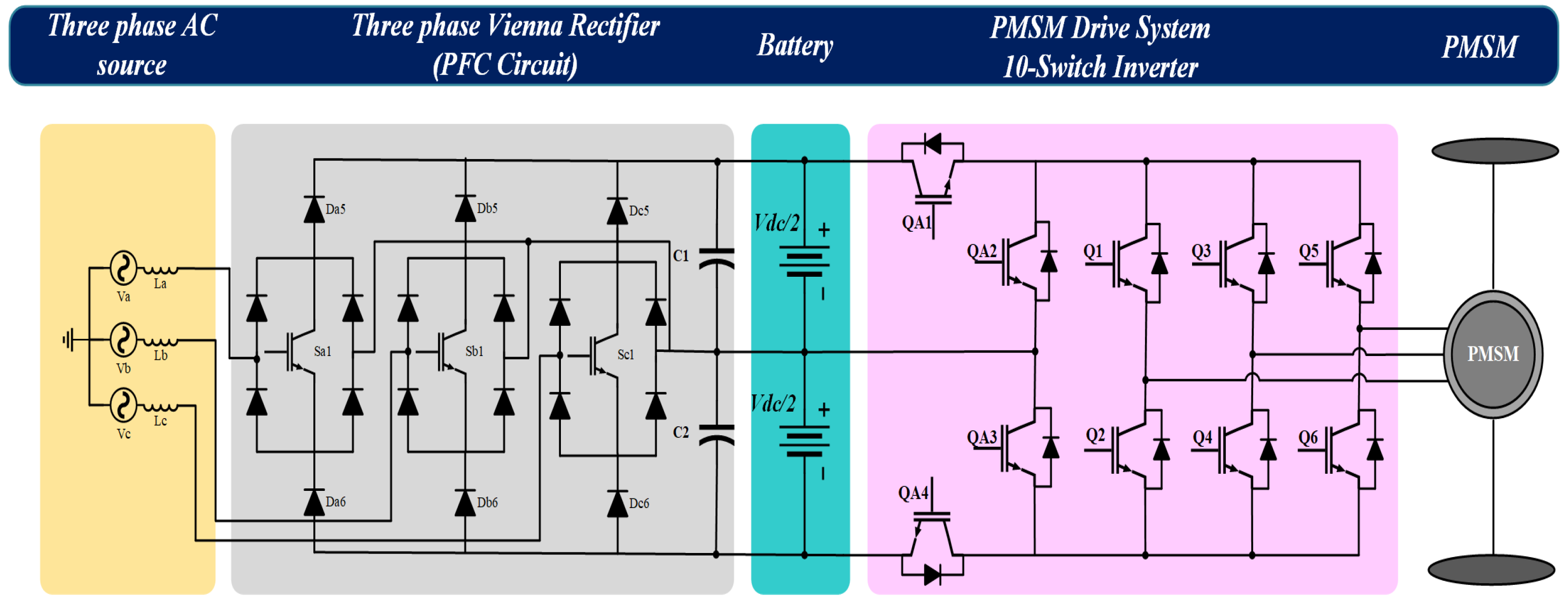
:1. Introduction
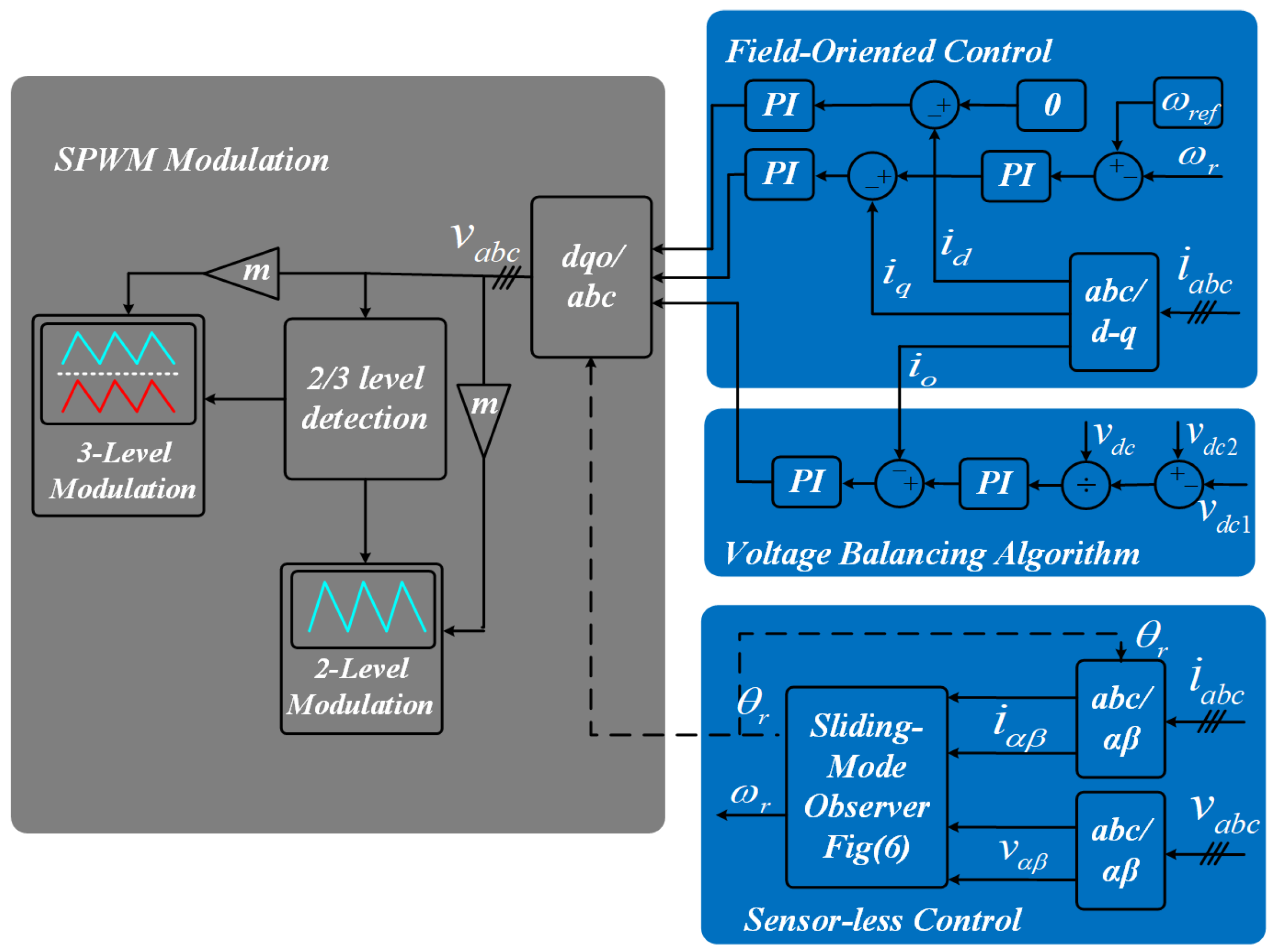
2. Power Conversion System
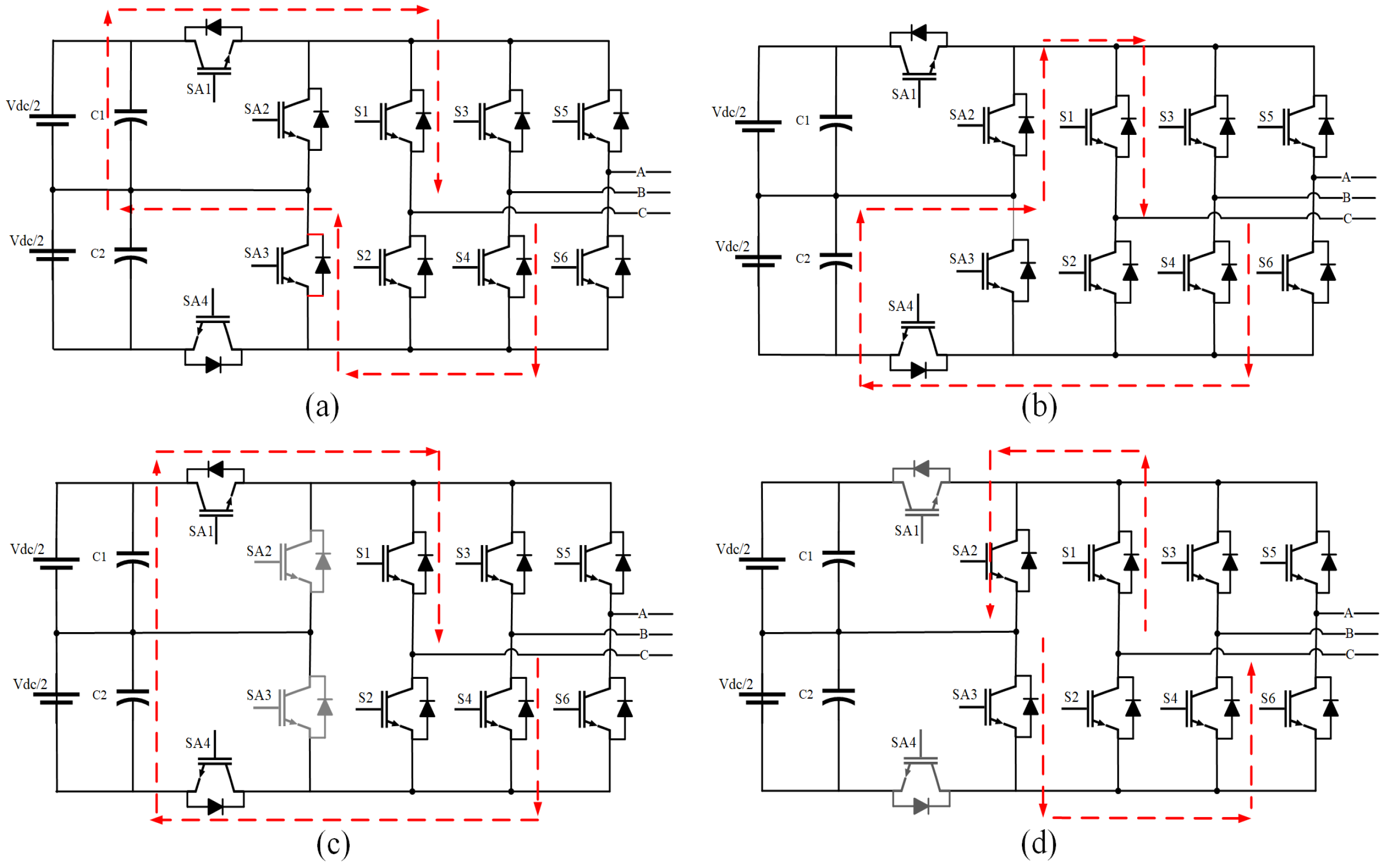
2.1. Machine Side Converter (10-Switch Inverter)
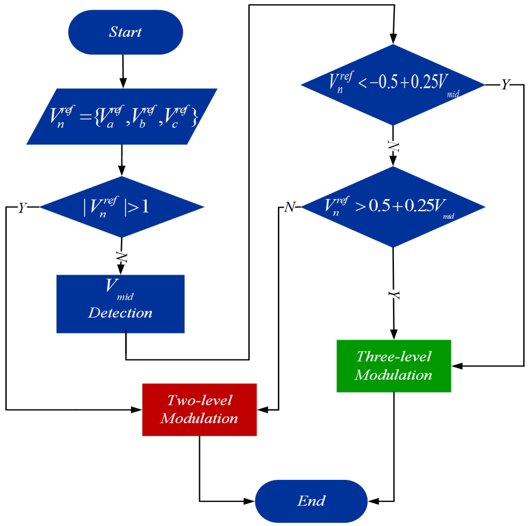
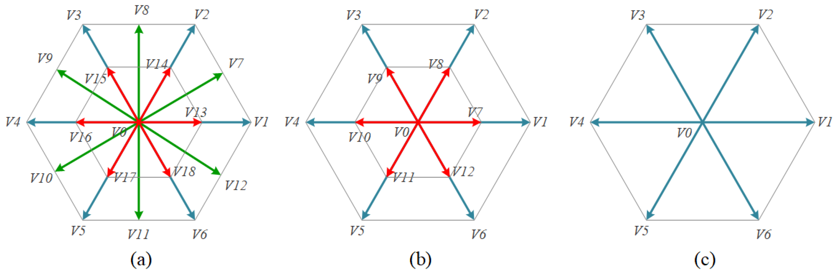
2.1.1. Modulation
2.1.2. Inverter Losses
3. Control Scheme
3.1. On-Board Charger
- Low voltage stress across switches;
- Low number of active switches and high efficiency;
- Ability to balance output voltages and control the neutral point voltage.
3.2. PMSM Model
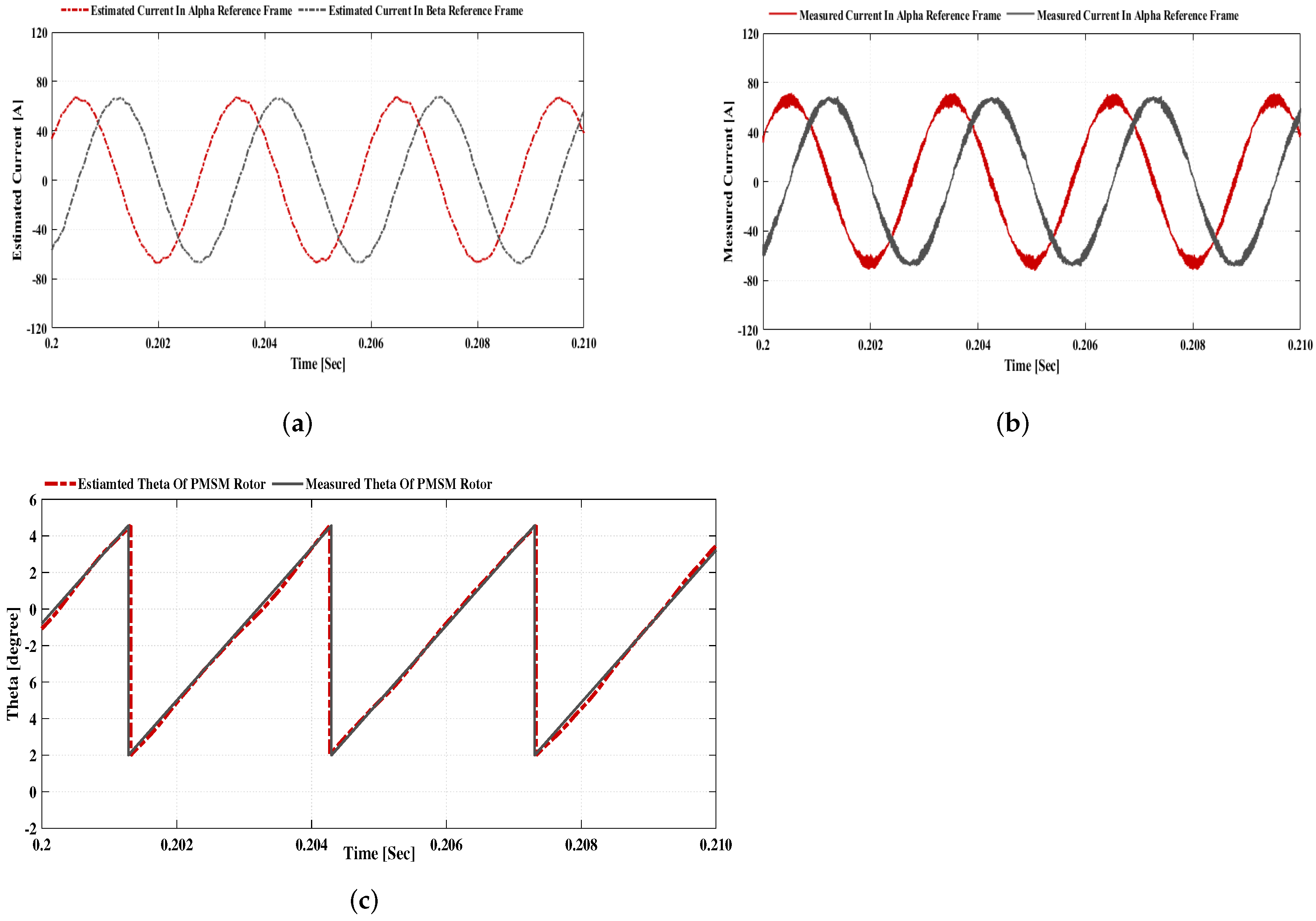
3.3. Sensorless Control Method
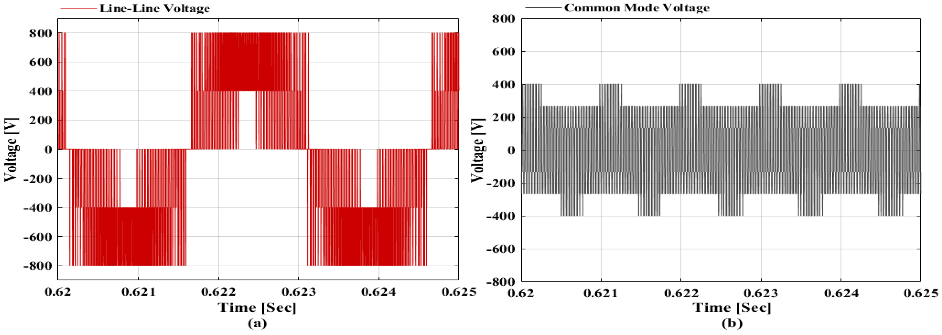
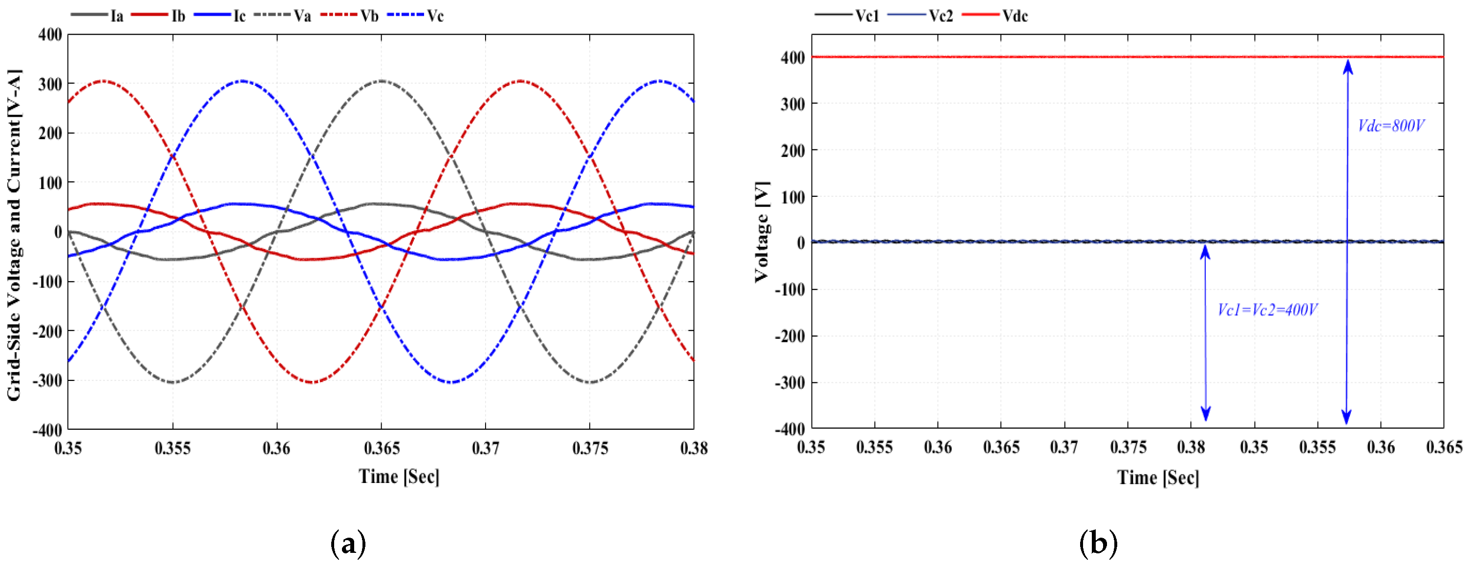
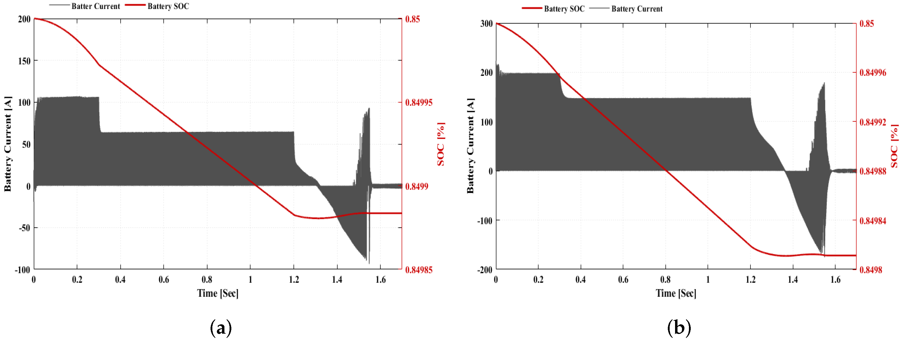
4. Simulation Results
5. Conclusions
Author Contributions
Funding
Institutional Review Board Statement
Informed Consent Statement
Data Availability Statement
Conflicts of Interest
References
- Omahne, V.; Knez, M.; Obrecht, M. Social Aspects of Electric Vehicles Research—Trends and Relations to Sustainable Development Goals. World Electr. Veh. J. 2021, 12, 15. [Google Scholar] [CrossRef]
- Towoju, O.A.; Ishola, F.A. A case for the internal combustion engine powered vehicle. Energy Rep. 2020, 6 (Suppl. S2), 315–321. [Google Scholar] [CrossRef]
- Rezvani, Z.; Jansson, J.; Bodin, J. Advances in consumer electric vehicle adoption research: A review and research agenda. Transp. Res. Part D Transp. Environ. 2015, 34, 122–136. [Google Scholar] [CrossRef] [Green Version]
- Messagie, M. Life Cycle Analysis of the Climate Impact of Electric Vehicles. European Federation for Transport and Environment AISBL. Available online: https://www.transportenvironment.org/sites/te/files/publications/TE%20-%20draft%20report%20v04.pdf (accessed on 30 May 2018).
- Hawkins, T.R.; Gausen, O.M.; Strømman, A.H. Environmental impacts of hybrid and electric vehicles—A review. Int. J. Life Cycle Assess. 2012, 17, 997–1014. [Google Scholar] [CrossRef]
- Broadbent, G.; Metternicht, G.; Drozdzewski, D. An Analysis of Consumer Incentives in Support of Electric Vehicle Uptake: An Australian Case Study. World Electr. Veh. J. 2019, 10, 11. [Google Scholar] [CrossRef] [Green Version]
- Keyser, M.; Pesaran, A.; Li, Q.; Santhanagopalan, S.; Smith, K.; Wood, E.; Bloom, I.; Dufek, E.; Shirk, M.; Meintz, A.; et al. Enabling fast charging–battery thermal considerations. J. Power Sources 2017, 367, 228–236. [Google Scholar] [CrossRef]
- Sanguesa, J.A.; Torres-Sanz, V.; Garrido, P.; Martinez, F.J.; Marquez-Barja, J.M. A Review on Electric Vehicles: Technologies and Challenges. Smart Cities 2021, 4, 372–404. [Google Scholar] [CrossRef]
- Emadi, A. Advanced Electric Drive Vehicles; CRC Press: Boca Raton, FL, USA, 2014; ISBN 978-1-4665-9769-3. [Google Scholar]
- Aghabali, I.; Bauman, J.; Kollmeyer, P.; Wang, Y.; Bilgin, B.; Emadi, A. 800 V Electric Vehicle Powertrains: Review and Analysis of Benefits, Challenges, and Future Trends. IEEE Trans. Transp. Electrif. 2020, 7, 927–948. [Google Scholar] [CrossRef]
- Yilmaz, M.; Krein, P.T. Review of the Impact of Vehicle-to-Grid Technologies on Distribution Systems and Utility Interfaces. IEEE Trans. Power Electron. 2013, 28, 5673–5689. [Google Scholar] [CrossRef]
- Abad, G. Power Electronics and Electric Drives for Traction Applications; John Wiley & Sons: Hoboken, NJ, USA, 2016. [Google Scholar]
- Gurpinar, E.; Ozpineci, B. Loss Analysis and Mapping of a SiC MOSFET Based Segmented Two-Level Three-Phase Inverter for EV Traction Systems. In Proceedings of the 2018 IEEE Transportation Electrification Conference and Expo (ITEC), Long Beach, CA, USA, 13–15 June 2018; pp. 1046–1053. [Google Scholar]
- Reimers, J.; Dorn-Gomba, L.; Mak, C.; Emadi, A. Automotive Traction Inverters: Current Status and Future Trends. IEEE Trans. Veh. Technol. 2019, 68, 3337–3350. [Google Scholar] [CrossRef]
- Peng, F.Z.; Shen, M.; Holland, K. Application of Z-Source Inverter for Traction Drive of Fuel Cell—Battery Hybrid Electric Vehicles. IEEE Trans. Power Electron. 2007, 22, 1054–1061. [Google Scholar] [CrossRef]
- Pillay, P.; Krishnan, R. Modeling, simulation, and analysis of permanent-magnet motor drives. I. The permanent-magnet synchronous motor drive. IEEE Trans. Ind. Appl. 1989, 25, 265–273. [Google Scholar] [CrossRef]
- Vas, P. Sensorless Vector and Direct Torque Control; Oxford University Press: Oxford, UK, 1998. [Google Scholar]
- Bolognani, S.; Oboe, R.; Zigliotto, M. Sensorless full-digital pmsm drive with ekf estimation of speed and rotor position. IEEE Trans. Ind. Electron. 1999, 46, 184–191. [Google Scholar] [CrossRef]
- Xu, D.; Wang, B.; Zhang, G.; Wang, G.; Yu, Y. A review of sensor-less control methods for ac motor drives. CES Trans. Electr. Mach. Syst. 2018, 2, 104–115. [Google Scholar] [CrossRef]
- Lian, K.-Y.; Chiang, C.-H.; Tu, H.-W. Lmi-based sensorless control of permanent-magnet synchronous motors. IEEE Trans. Ind. Electron. 2007, 54, 2769–2778. [Google Scholar] [CrossRef]
- Genduso, F.; Miceli, R.; Rando, C.; Galluzzo, G.R. Back emf sensorless-control algorithm for high-dynamic performance pmsm. IEEE Trans. Ind. Electron. 2009, 57, 2092–2100. [Google Scholar] [CrossRef]
- Kivanc, O.C.; Ozturk, S.B. Sensorless PMSM Drive Based on Stator Feedforward Voltage Estimation Improved With MRAS Multiparameter Estimation. IEEE/ASME Trans. Mech. 2018, 23, 1326–1337. [Google Scholar] [CrossRef]
- Liang, D.; Li, J.; Qu, R.; Kong, W. Adaptive second-order sliding-mode observer for pmsm sensorless control considering vsi nonlinearity. IEEE Trans. Power Electron. 2017, 33, 8994–9004. [Google Scholar] [CrossRef]
- Metwly, M.Y.; Abdel-Majeed, M.S.; Abdel-Khalik, A.S.; Hamdy, R.A.; Hamad, M.S.; Ahmed, S. A Review of Integrated On-Board EV Battery Chargers: Advanced Topologies, Recent Developments and Optimal Selection of FSCW Slot/Pole Combination. IEEE Access 2020, 8, 85216–85242. [Google Scholar] [CrossRef]
- Vu, H.; Choi, W. A Novel Dual Full-Bridge LLC Resonant Converter for CC and CV Charges of Batteries for Electric Vehicles. IEEE Trans. Ind. Electron. 2018, 65, 2212–2225. [Google Scholar] [CrossRef]
- Singh, B.; Kushwaha, R. A PFC Based EV Battery Charger Using a Bridgeless Isolated SEPIC Converter. IEEE Trans. Ind. Appl. 2020, 56, 477–487. [Google Scholar] [CrossRef]
- Tu, H.; Feng, H.; Srdic, S.; Lukic, S. Extreme Fast Charging of Electric Vehicles: A Technology Overview. IEEE Trans. Transp. Electrif. 2019, 5, 861–878. [Google Scholar] [CrossRef]
- Mihalache, L. A Hybrid 2/3 Level Converter With Minimum Switch Count. In Proceedings of the Conference Record of the 2006 IEEE Industry Applications Conference Forty-First IAS Annual Meeting, Tampa, FL, USA, 8–12 October 2006; pp. 611–618. [Google Scholar]
- Najafi, P.; Houshmand Viki, A.; Shahparasti, M.; Seyedalipour, S.S.; Pouresmaeil, E. A Novel Space Vector Modulation Scheme for a 10-Switch Converter. Energies 2020, 13, 1855. [Google Scholar] [CrossRef] [Green Version]
- Taha, W.; Nahid-Mobarakeh, B.; Bauman, J. Efficiency Evaluation of 2L and 3L SiC-Based Traction Inverters for 400V and 800V Electric Vehicle Powertrains. In Proceedings of the 2021 IEEE Transportation Electrification Conference & Expo (ITEC), Chicago, IL, USA, 21–25 June 2021. [Google Scholar]
- Berringer, K.; Marvin, J.; Perruchoud, P. Semiconductor power losses in AC inverters. In Proceedings of the Conference Record of the 1995 IEEE Industry Applications Conference Thirtieth IAS Annual Meeting, Orlando, FL, USA, 8–12 October 1995; Volume 1, pp. 882–888. [Google Scholar]
- Hang, L.; Li, B.; Zhang, M.; Wang, Y.; Tolbert, L.M. Equivalence of SVM and Carrier-Based PWM in Three-Phase/Wire/Level Vienna Rectifier and Capability of Unbalanced-Load Control. IEEE Trans. Ind. Electron. 2014, 61, 20–28. [Google Scholar] [CrossRef]
- Kim, H.; Son, J.; Lee, J. A High-Speed Sliding-Mode Observer for the Sensorless Speed Control of a PMSM. IEEE Trans. Ind. Electron. 2011, 58, 4069–4077. [Google Scholar]


| Vector Categories | Space Vector | Switching State |
|---|---|---|
| Zero Vectors (0) | , , | |
| Small Vectors () | P-type | |
| N-type | ||
| Large Vectors () | , , | |
| , , |
| PMSM Parameter | Value | Control Parameter | Value |
|---|---|---|---|
| PMSM Rated Speed | 2500 r/min | AC Input Voltage(rms) | 380 V |
| PMSM Rated Torque | 100 N·m | DC-link Voltage | 800 V |
| Rated Power | 26 kW | Switching Frequency | 30 KHz |
| Stator Inductance/Resistance | 1 mH/0.25 Ω | k (SMO Gain) | 2000 |
| Number of Poles | 8 | a (Sigmoid Constant) | 0.054 |
| PMSM Parameter | 400 V System | 800 V System |
|---|---|---|
| Rated power (kW) | 30 | 30 |
| Rated voltage (V) | 250–450 | 450–600 |
| Max current (A) | 150 | 95 |
| Max torque (N·m) | up to 150 | up to 100 |
| Max speed (r/min) | up to 3000 | up to 6000 |
| Flux linkage (mWb) | 45 | 98 |
| Moment of inertia (kg·m2) | 0.08 | 0.08 |
| Inverter Topology | Leg | Part Number | Blocking Voltage | Continuous Current Rating | Rds,on |
|---|---|---|---|---|---|
| VSI | All three legs | C3M0025065D | 650 (V) | 97 (A) | 25 (mΩ) |
| 10-Switch | The leg with four series switches | C3M0015065D | 650 (V) | 81 (A) | 15 (mΩ) |
| 10-Switch | Legs with two series switches | C3M0021120D | 1200 (V) | 81 (A) | 21 (mΩ) |
Publisher’s Note: MDPI stays neutral with regard to jurisdictional claims in published maps and institutional affiliations. |
© 2022 by the authors. Licensee MDPI, Basel, Switzerland. This article is an open access article distributed under the terms and conditions of the Creative Commons Attribution (CC BY) license (https://creativecommons.org/licenses/by/4.0/).
Share and Cite
Sadeghi, Z.; Shahparasti, M.; Rajaei, A.; Laaksonen, H. Three-Level Reduced Switch AC/DC/AC Power Conversion System for High Voltage Electric Vehicles. Sustainability 2022, 14, 1620. https://doi.org/10.3390/su14031620
Sadeghi Z, Shahparasti M, Rajaei A, Laaksonen H. Three-Level Reduced Switch AC/DC/AC Power Conversion System for High Voltage Electric Vehicles. Sustainability. 2022; 14(3):1620. https://doi.org/10.3390/su14031620
Chicago/Turabian StyleSadeghi, Zahra, Mahdi Shahparasti, Amirhossein Rajaei, and Hannu Laaksonen. 2022. "Three-Level Reduced Switch AC/DC/AC Power Conversion System for High Voltage Electric Vehicles" Sustainability 14, no. 3: 1620. https://doi.org/10.3390/su14031620
APA StyleSadeghi, Z., Shahparasti, M., Rajaei, A., & Laaksonen, H. (2022). Three-Level Reduced Switch AC/DC/AC Power Conversion System for High Voltage Electric Vehicles. Sustainability, 14(3), 1620. https://doi.org/10.3390/su14031620