1. Introduction
By the end of January 2021, the total weight of space debris had reached 8400 tons, with 128 million debris with a size of 0.1–1 cm, about 90,000 debris with a size of 1–10 cm and 34,000 debris with a size greater than 10 cm [
1]. The has been a rapid increase in the amount of space debris and the increasingly serious space debris environment poses a serious challenge to the sustainable development of space activities [
2,
3,
4,
5,
6,
7]. Active removal of space debris has become a common consensus [
8]. Among the currently proposed active debris removal technologies [
9,
10], space-energy driven laser-ablation debris removal technology has attracted extensive attention because of its wide removal range, fast response speed, adaptability to multiple scale debris and high cost-effectiveness ratio. This method has high requirements for lasers and mainly involves the problems of laser energy storage, instantaneous release and rapid heat dissipation. The controllability of laser energy and the high conversion rate of space energy make space-energy driven laser systems more advantageous [
11,
12,
13]. The perigee of space debris is reduced under the irradiation of high-energy laser and finally the space debris falls into the atmosphere to be removed.
Since the proposal of a space-energy driven laser-ablation removal scheme in 1989, scholars have designed a variety of removal schemes for different removal requirements [
14,
15], debris orbit [
16,
17], shape [
18,
19] and attitude characteristics [
20,
21]. Removal processes and effects under different removal scenarios through different orbit change models [
22] and relative position relationships have been fully studied [
23].
Laser energy efficiency is a comprehensive index to evaluate the debris removal process. It is a key parameter to be considered in system design and mission planning. However, the efficiency of laser during the removal process has yet to be considered. The objective of this paper is to analyze the energy efficiency of a space-energy driven active laser-ablation debris removal system. The specific objectives are: (a) to detail the energy efficiency of the space-energy driven active laser-ablation debris removal system, and (b) to study the effects of laser energy, laser frequency and laser range on the energy efficiency.
2. Analysis Methods
2.1. Physical Model
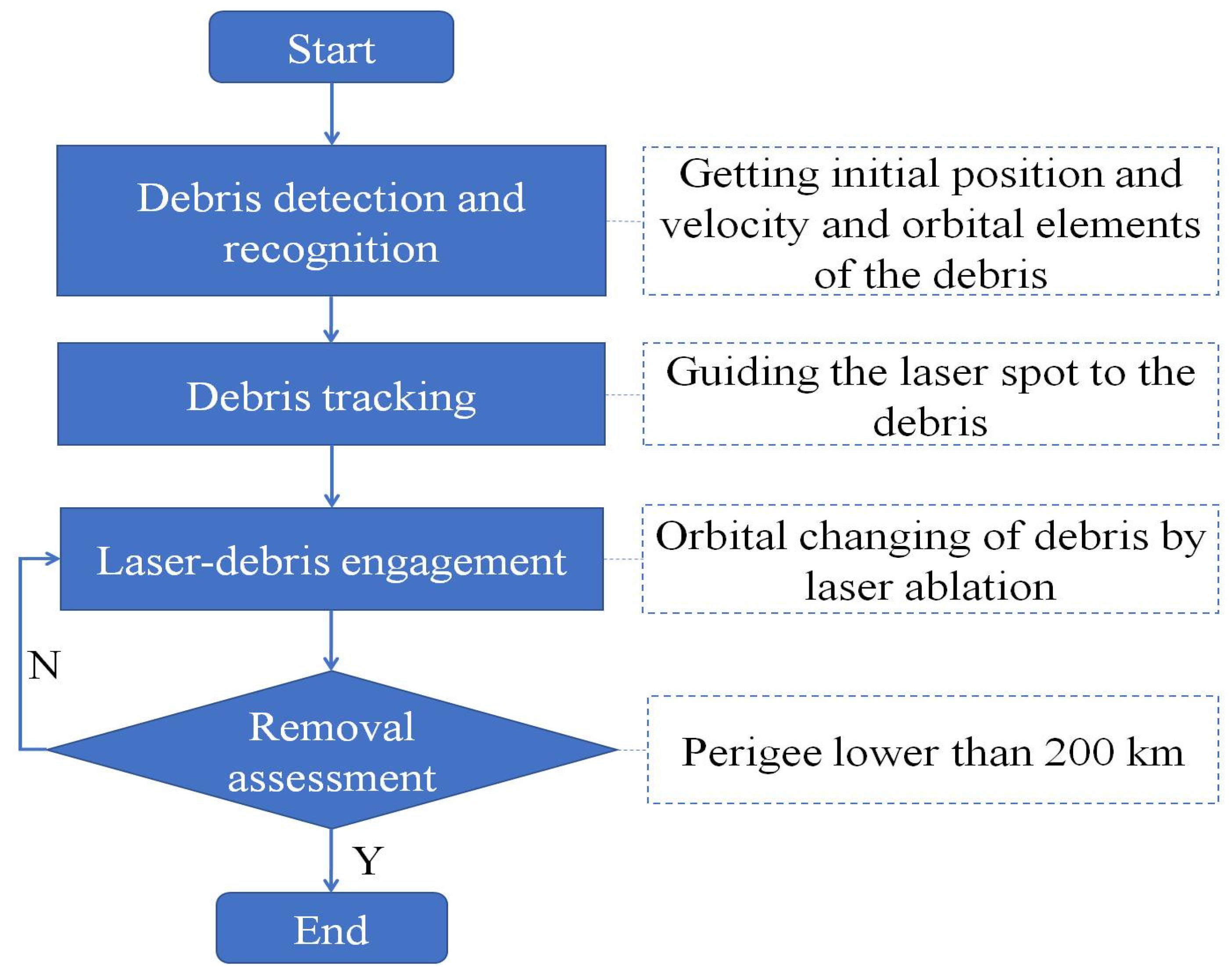
Debris removal system with laser-ablation driven by space-energy mainly includes debris detection, identification, tracking, irradiation, and removal evaluation. Among them, debris detection mainly extracts the target debris from the star background through the visible light characteristics of debris. It obtains the location, velocity and rough orbit information of debris. According to the information obtained from debris detection, the aim of a tracking system is to accurately determine the debris orbit, and to ensure that the far-field spot can accurately reach the debris surface. When the debris enters a certain range, the laser starts to emit the laser pulses, which reach the debris surface through the tracking system.After the space debris is irradiated by pulsed laser, the surface melts, vaporizes and plasmas, and the ablation products are sprayed outward to obtain an impulse, which can change the orbit of debris and finally remove it. Based on the measurement information of the detection system, the removal system evaluates whether the laser driving has achieved the expected effect. The process is shown in
Figure 1.
Without considering the influence of orbital perturbation, the laser ablation affects the motion state of debris in the above process. The laser energy, frequency, pulse width and wavelength all affect the size and direction of velocity increment in the driving process [
24,
25,
26]. The existing lasers usually have fixed pulse width and output wavelength. Due to the laser energy density threshold (10
8 W/cm
2) of laser ablation at a given laser energy, a longer distance means a larger field spot area, which results in the rapid decline of laser energy density. Therefore, there is an effective laser range where debris can obtain the velocity increment caused by laser irradiation. To sum up, the key parameters of the removal system affecting the motion state of debris are the laser energy, frequency and range powered by space energy.
2.2. Mathematic Models
Position and velocity information of the space debris and removal system can be obtained by giving initial orbital elements. The process of debris removal by a space-energy driven laser-ablation system is as follows:
Perigee of debris is obtained according to the initial debris orbital elements, if the perigee is lower than 200 km, the debris can be removed by itself. Otherwise, we go to step 2.
The position and velocity of debris and removal system are obtained from initial orbital elements. According to the current position and velocity information of debris and removal system, determine if the debris can be in the range of the laser. If the debris can be in the laser range, the speed increment will be obtained after being irradiated by the laser. Otherwise, the removal system cannot ablate and drive the debris. For the debris, which can be in the laser range, we further proceed to step 3.
For the debris in a laser range at a certain time in the future, the relative position and distance at each time are obtained through the orbital evolution of the debris and the removal system. When the relative distance is less than the laser range R, it indicates that the debris is within the laser range, and then the orbital elements are changed by laser ablation.
When the distance between the debris and the removal system is greater than laser range R, it indicates that the laser cannot ablate and drive the debris. In this case, go to step 1 and analyze the perigee of the debris.
When the debris is in the laser range again, follow the steps 1–4 until the debris is not in the laser range or it has been removed. The above process is shown in
Figure 2.
2.3. Irradiation Time Window
Given orbital elements of the debris {
hD, eD, iD, ΩD, ωD, θD} and removal system {
hL, eL, iL, ΩL, ωL, θL}, the period of the removal system is:
The period of the debris is:
The nearest distance between the debris and removal system is the smallest relative distance within T = Max(TL,TD) period. It can be obtained by calculating the relative distance between debris and removal system at each time within T. The irradiation time window is determined by comparing it with laser range R. If the nearest distance is less than R, it means that debris can be irradiated by laser at some time.
2.4. Laser Ablation
The velocity increment Δ
v of the debris with mass
m ablated by a laser
pulse with energy
E with the impulse coupling coefficient
Cm is:
The instantaneous velocity of debris after the ablation is v1 = v0 + Δv, where v0 is the initial velocity of debris before ablation. At this position, the change of orbital elements caused by the change of velocity is obtained from the conversion relationship between position velocity and orbital elements.
2.5. Orbit Evolution
When the position
r0 and velocity
v0 at the initial
t0 time are known, the position
r and velocity
v at given time can be obtained from the Lagrange coefficient and its first derivative according to the following expressions [
27]:
The Lagrange coefficients expressed by using global variable
χ and Stamf function are as follows:
where
α is the reciprocal of long half axis:
For elliptical orbits, α > 0.
2.6. Perigee of Debris
After being ablated many times until the debris cannot enter the laser range, the orbital elements of debris are {
hD1, eD1, iD1, ΩD1, ωD1, θD1}, and the perigee of debris is:
The orbital descent effect of debris can be evaluated by the perigee changing of debris before and after laser ablation.
2.7. Energy Efficiency
The energy efficiency effi
t is defined as the ratio of the currently lowered perigee height to the consumed laser energy, which mainly represents the dynamic change trend of laser energy efficiency with time in the process of debris removal. That is, the perigee descent height Δ
Ht divided by the total energy
∑Et at time t:
If the energy efficiency is negative, it indicates that the perigee increases gradually driven by the laser.
3. Results and Discussion
Taking the space debris with the perigee of with 800 km, located in the densest distribution of space debris, as an example, the removal process and influence of the key parameters of the system on the energy efficiency were studied from two different running planes. It is assumed that the velocity increment of laser ablation pointed to the direction of space debris along the removal platform without considering the influence of orbital perturbation.
The orbital elements of space debris are shown in
Table 1.
The orbital elements of the removal system under two removal circumstances are shown in
Table 2. In the initial state, the removal system is located 1 km in front of the debris running direction.
In a large number of experimental studies on impulse coupling of laser ablation target, a variety of experiments with different lasers (continuous laser, pulsed laser), different pulse widths (ns, ps, and fs) and different wavelengths (1064 nm, 532 nm) have been carried out [
28]. Based on this, there are many debris removal schemes under different laser parameters. Referring to the previous experimental data and the current debris removal scheme design [
29], in order to simplify the research, the laser ablation parameters are selected as
Table 3.
3.1. Effect of Laser Energy
3.1.1. Same Orbital Plane
1. Perigee changing
The perigee of space debris with time under different laser energies when the removal system is coplanar with space debris is shown in
Figure 3. The perigee of space debris does not change significantly when irradiated by 10 J within 100 s. Perigee below 200 km allows for space debris to finally be removed within 76 s when irradiated by 100 J. However, space debris cannot be removed when irradiated by 500 J and 1000 J, even if the irradiation lasts almost 32 s and 22 s, respectively.
Figure 3 shows that less irradiation time with higher laser energy, which resulted in a greater decline of the perigee per unit time. It is indicated that a greater velocity increment was obtained by space debris under a single laser shot with higher laser energy, while there was less time for the space debris to be located in the laser range. Despite the rapid decline in the perigee of space debris, the cumulative velocity increment obtained does not meet the requirements of debris removal.
2. Energy efficiency
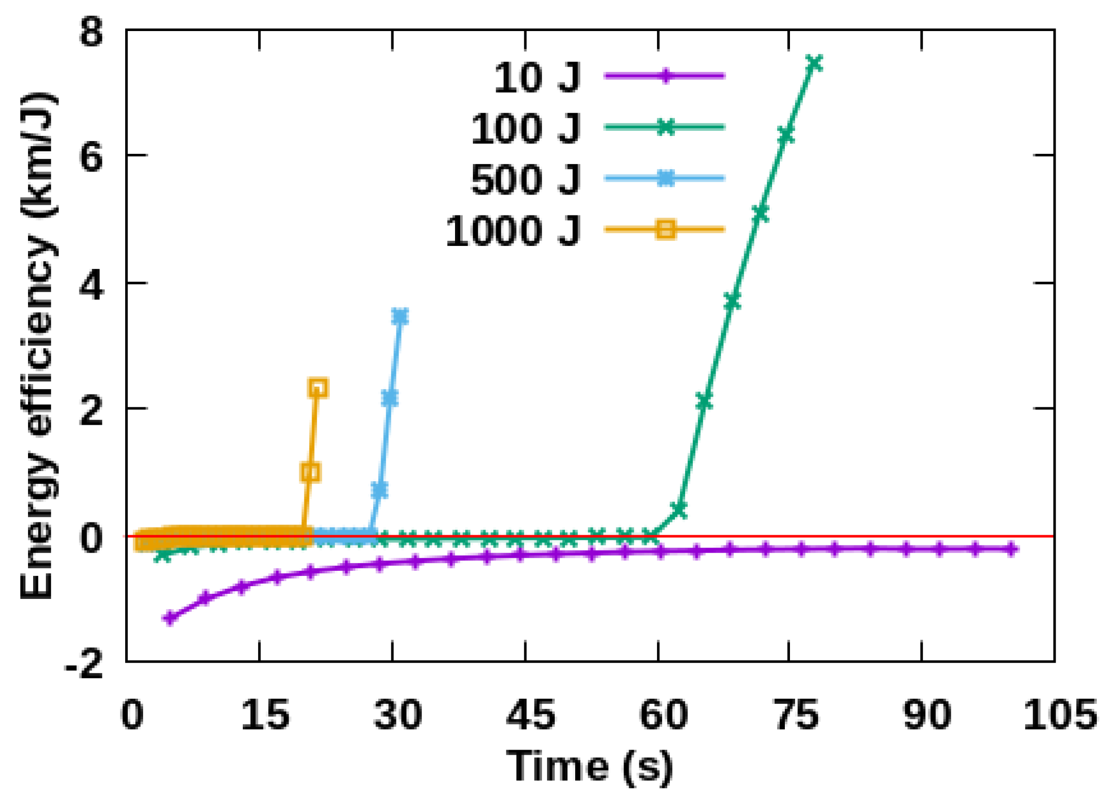
The energy efficiency with time under different laser energy when the removal system is coplanar with space debris is shown in
Figure 4. The energy efficiency gradually increased from −1.5 km/J to 0 km/J when laser energy is 10 J, which means the perigee of space debris is increasing. The energy efficiency gradually increased from −0.2 km/J to 7.8 km/J within 76 s when the energy is 100 J, from 0 km/J to 3.8 km/J within 32 s with 500 J and from 0 km/J to 2.9 km/J within 22 s with 1000 J respectively. The trend shows that lower laser energy means less energy efficiency in the initial state. A higher energy density would lead to a rapid increase in the energy efficiency. It indicates that a greater velocity increment is obtained by space debris under single driving with higher laser energy, which results in less time for space debris to be located in the laser range. The cumulative velocity increment gradually increases when it is driven by multiple times with lower laser energy, and the perigee changing per unit time is faster than before.
3.1.2. Different Orbital Planes
1. Perigee changing
The perigee of space debris with time under different laser energy when the removal system is not coplanar with space debris is shown in
Figure 5. Perigee is at 192 km within 4800 s with 10 J, 195 km within 2880 s with 100 J, 226 km within 3050 s with 500 J and 198 km in 2800 s with 1000 J. The perigee presents an oscillated process despite the perigee finally going down. The energy efficiency was significantly lower than the coplanar case. It indicates that in the case of different planes, relative position of space debris and the removal system change with time, and the direction of incremental velocity is inconsistent with the plane of space debris movement. The direction of cumulative velocity increment is changed from time to time, which results in the oscillation trend of perigee.
2. Energy efficiency
The change of energy efficiency with time under different laser energy when the removal system is not coplanar with space debris is shown in
Figure 6. The energy efficiency gradually oscillates from −0.1 km/J to 1.4 km/J within 4800 s with 10 J. During this period, the energy efficiency is changed repeatedly in the positive and negative directions. When the laser energy is 100 J, the energy efficiency gradually increases from −0.01 km/J to 0.25 km/J within 2880 s. The energy efficiency always oscillates around 0 km/J when the laser energy is 500 J and 1000 J. It shows that less irradiation time and low energy efficiency are obtained with high laser energy. It is indicated that the varying relative position between removal system and space debris leads to the continuous change of the velocity increment obtained by the space debris, which results in the oscillation of energy efficiency.
3.2. Effect of Laser Energy
3.2.1. Same Orbital Plane
1. Perigee changing
The perigee of space debris under different laser frequencies when the removal system is coplanar with space debris is shown in
Figure 7. Space debris cannot be removed under the frequency of 1 Hz and 10 Hz. The perigee is at 198 km within 78 s with 100 Hz, 185 km within 31 s with 100 Hz and 199 km within 21 s with 1000 Hz.
Figure 7 shows that the amplitude gradually increases with the increase in time, and the decline of perigee presents an obvious cumulative effect. Higher frequency meansless driving time which results in more perigee descent. It indicates that a greater velocity increment is obtained per unit time with higher frequency.
2. Energy efficiency
The energy efficiency with time at different laser frequencies when the removal system is coplanar with space debris is shown in
Figure 8. The energy efficiency is negative when the frequencies are 1 Hz and 10 Hz, which indicates that the perigee gradually increases with time. When the frequencies are 100 Hz, 500 Hz and 1000 Hz, the energy efficiency increases gradually with the increase in time. It indicates that the greater velocity increment is obtained per unit time at high frequency.
3.2.2. Different Orbital Planes
1. Perigee changing
The perigee of space debris at different frequencies when the removal system is not coplanar with space debris is shown in
Figure 9. When the frequency is 1 Hz, the perigee of space debris gradually increases within 4850 s. The perigee is at 190 km within 4600 s with 10 Hz, 195 km within 2850 s with 100 Hz, 199 km with 3150 s with 500 Hz and 194 km within 2800 s with 1000 Hz. The perigee change shows an oscillatory downward trend when the removal system is not coplanar with space debris. It indicates that a greater velocity increment is obtained per unit time with higher frequency. However, the direction of cumulative velocity increment in different planes changes because of the relative position between removal system and space debris. The magnitude of velocity increment in the direction of debris velocity changes from time to time, which results in the oscillation of perigee descent.
2. Energy efficiency
The energy efficiency at different frequencies when the removal system is not coplanar with space debris is shown in
Figure 10. When the frequency is 1 Hz, the energy efficiency is negative and it increases gradually with time, indicating that the perigee is increased gradually with time. The energy efficiency oscillates around 0 km/J with time when the frequencies are 10 Hz, 100 Hz, 500 Hz and 1000 Hz, which are consistent with the downward trend of perigee oscillation in the
Figure 9. It indicates that the velocity increment generated by high energy is inconsistent with the velocity direction, resulting in low energy utilization.
3.3. Effect of Laser Range
3.3.1. Same Orbital Plane
1. Perigee changing
The perigee of space debris in the range of 100 km and 500 km when the removal system is coplanar with space debris is shown in
Figure 11. It shows that the perigee of space debris is decreased from 800 km to 198 km within 78 s. In the two ranges, the trends of perigee are completely consistent. It indicates that the change of velocity increment in the process of debris removal is mainly related to the laser driving process. When the debris is within the range of the laser, distant range of the laser has no effect on the laser driving process, but only the number of debris can be removed by the removal system. Therefore, there is no effect on the perigee changing of space debris with different laser ranges.
2. Energy efficiency
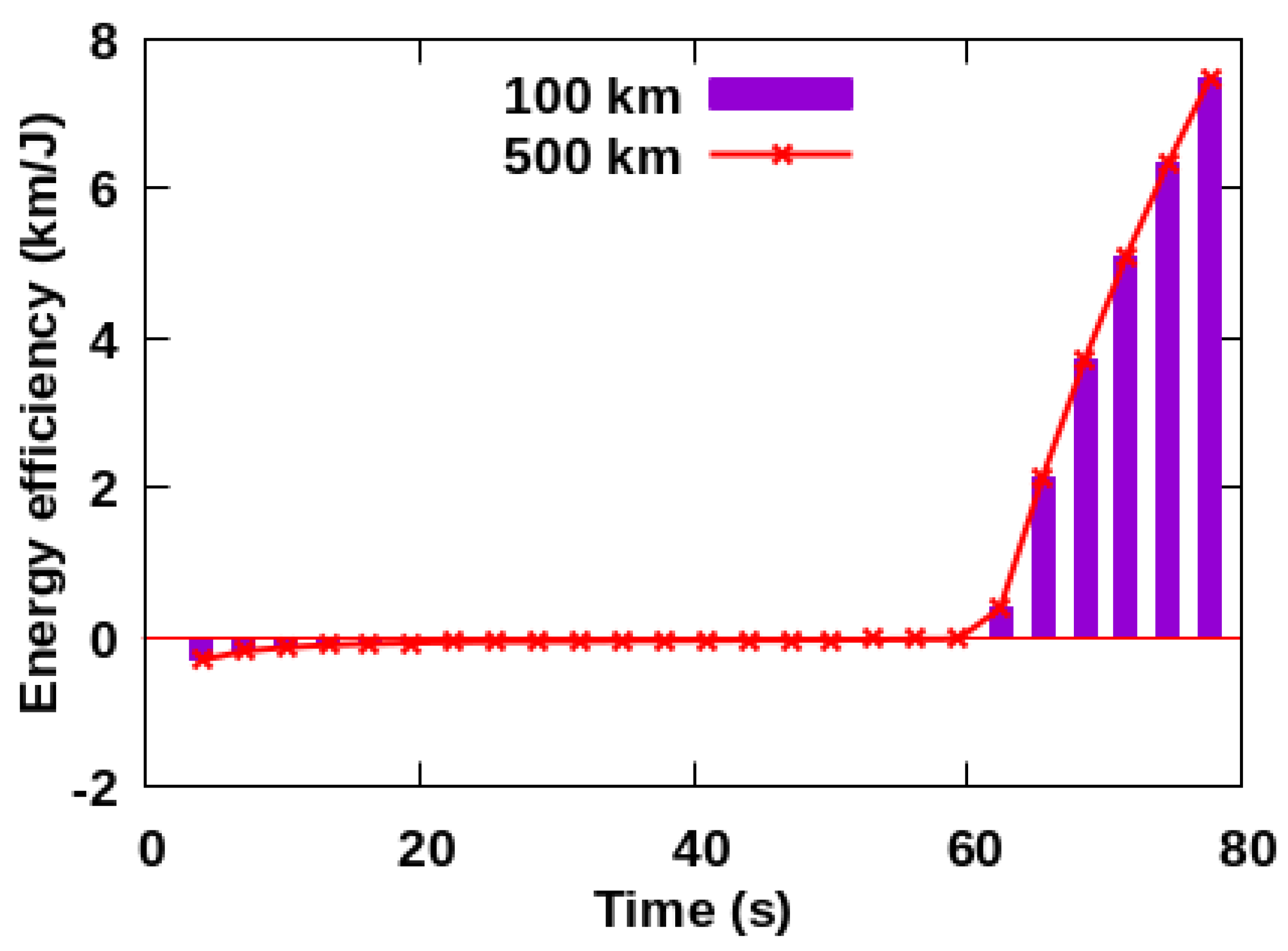
The energy efficiency with time in the removal range of 100 km and 500 km when the removal platform is coplanar with space debris is shown in
Figure 12. In the two removal ranges, both the energy efficiencies are gradually increased from −0.5 km/J to 7.5 km/J. The increase in time leads to energy efficiency increasing significantly, which is completely consistent with the results in
Figure 11. It shows that the laser range has no effect on energy efficiency.
3.3.2. Different Orbital Planes
1. Perigee changing
The perigee of debris in the removal range of 100 km and 500 km when the removal system is not coplanar with space debris is shown in
Figure 13. At the two states, the perigee of debris is decreased from 800 km to 195 km in 2800 s, and the change trend is completely the same. It shows that the laser range has no effect on the perigee change of debris.
2. Energy efficiency
The energy efficiency with time in the removal range of 100 km and 500 km when the removal system is not coplanar with space debris is shown in
Figure 14. In the two removal ranges, the energy efficiency gradually increases from −0.03 km/J to 0.22 km/J, and the trend is completely consistent. With the increase in time, the energy efficiency shows an oscillatory change, which is completely consistent with the results in
Figure 6. It shows that the laser range has no effect on energy efficiency.
4. Conclusions
In this paper, system configurations and working processes of a space-energy driven laser-ablation debris removal system are introduced, and an orbit transfer model is established to study the perigee change and energy efficiency under various laser energies, frequencies and ranges. Some conclusions have been reached.
When the space debris is coplanar with the removal system, the space debris cannot be removed with 10 J energy, despite the driving time being 100 s, and the energy efficiency is between −2 km/J and 8 km/J. In the case of different planes, the driving time is 4800 s and the energy efficiency is from −0.5 km/J to 1.5 km/J. Space debris cannot be removed at the frequency of 1–10 Hz, and the energy efficiency is between −0.0004 km/J and 0.0008 km/J under coplanar and out of plane conditions, which is significantly lower than the energy change. When the laser ranges are 100 km and 500 km, the removal process and energy efficiency remain unchanged.
At the coplanar state, there is a cumulative effect on the perigee and energy efficiency with different energies and frequencies. The variation increases gradually with the increase in time. At the different plane states, the perigee and energy efficiency under different frequencies and energy show an oscillation, the variation fluctuates up and down, but the overall increase or decrease trend remains unchanged with the increase in time. The laser range does not affect the perigee change and energy efficiency of space debris in both coplanar and different plane situations.
Author Contributions
W.Y., H.F. and Z.S. designed the study and simulation; W.Y. and C.C. did the code; W.Y., Q.W. and C.C. conducted the data analysis; W.Y. and C.C. provided the mathematical methods; W.Y., Z.S. and H.Z. drafted the paper; W.Y., H.F., H.Z., Q.W. and C.C. edited the paper. All authors have read and agreed to the published version of the manuscript.
Funding
This work was financially supported by Special Fund for Space Debris Project (KJSP2020010304).
Institutional Review Board Statement
Not applicable.
Informed Consent Statement
Not applicable.
Data Availability Statement
Not applicable.
Acknowledgments
A special thanks is expressed to Zizheng Gong for his support in simulation algorithm.
Conflicts of Interest
The authors declare no conflict of interest.
References
- Pardini, C.; Anselmo, L. Evaluating the impact of space activities in low earth orbit. Acta Astronaut. 2021, 184, 11–22. [Google Scholar] [CrossRef]
- Peltoniemi, J.I.; Wilkman, O.; Gritsevich, M.; Poutanen, M.; Halli, A.R.; Näränen, J.; Flohrer, T.; Mira, A.D. Steering reflective space debris using polarised lasers. Adv. Space Res. 2021, 67, 1721–1732. [Google Scholar] [CrossRef]
- Newman, C.; Dinsley, R.; Ralston, W. Introducing the law games: Predicting legal liability and fault in satellite operations. Adv. Space Res. 2021, 67, 3785–3792. [Google Scholar] [CrossRef]
- Pardini, C.; Anselmo, L. Environmental sustainability of large satellite constellations in low earth orbit. Acta Astronaut. 2020, 170, 27–36. [Google Scholar] [CrossRef]
- Bonnal, C.; Francillout, L.; Moury, M.; Aniakou, U.; Perez, J.C.D.; Mariez, J.; Michel, S. CNES technical considerations on space traffic management. Acta Astronaut. 2019, 167, 296–301. [Google Scholar] [CrossRef]
- Virgili, B.B.; Dolado, J.C.; Lewis, H.G.; Radtke, J.; Krag, H.; Revelin, B.; Cazaux, C.; Colombo, C.; Crowther, R.; Metz, M. Risk to space sustainability from large constellations of satellites. Acta Astronaut. 2016, 126, 154–162. [Google Scholar] [CrossRef] [Green Version]
- Lidtke, A.A.; Lewis, H.G.; Armellin, R.; Urrutxua, H. Considering the collision probability of Active Debris Removal missions. Acta Astronaut. 2017, 131, 10–17. [Google Scholar] [CrossRef] [Green Version]
- Gong, Z.; Xu, K.; Mu, Y.; Cao, Y. The space debris environment and the active debris removal techniques. Spacecr. Environ. Eng. 2014, 31, 129–135. [Google Scholar]
- Phipps, C.R.; Bonnal, C. A spaceborne, pulsed UV laser system for re-entering or nudging LEO debris, and re-orbiting GEO debris. Acta Astronaut. 2016, 118, 224–236. [Google Scholar] [CrossRef]
- Battistona, R.; Burgerb, W.J.; Cafagnac, A.; Manead, A.; Spataroe, B. A systematic study of laser ablation for space debris mitigation. J. Space Saf. Eng. 2017, 4, 36–44. [Google Scholar] [CrossRef]
- Herrera-Jaramillo, D.A.; Henao-Bravo, E.E.; González Montoya, D.; Ramos-Paja, C.A.; Saavedra-Montes, A.J. Control-Oriented Model of Photovoltaic Systems Based on a Dual Active Bridge Converter. Sustainability 2021, 13, 7689. [Google Scholar] [CrossRef]
- Al-Nimr, M.; Milhem, A.; Al-Bishawi, B.; Al Khasawneh, K. Integrating Transparent and Conventional Solar Cells TSC/SC. Sustainability 2020, 12, 7483. [Google Scholar] [CrossRef]
- Miao, H.; Zhang, L.; Liu, S.; Zhang, S.; Memon, S.; Zhu, B. Laser Sealing for Vacuum Plate Glass with PbO-TiO2-SiO2-RxOy Solder. Sustainability 2020, 12, 3118. [Google Scholar] [CrossRef] [Green Version]
- Phipps, C.R.; Baker, K.L.; Libby, S.B.; Liedahl, D.A.; Olivier, S.S.; Pleasance, L.D.; Rubenchik, A.; Trebes, J.E.; Victor, G.E.; Marcovici, B.; et al. Removing orbital debris with lasers. Adv. Space Res. 2012, 49, 1283–1300. [Google Scholar] [CrossRef] [Green Version]
- Wen, Q.; Yang, L.; Zhao, S.; Fang, Y.; Yi, W.; Ding, X.; Tao, L. Research on de-orbiting model of small scale space debris removal using space-based laser. Infrared Laser Eng. 2018, 48, 35–41. [Google Scholar]
- Li, M.; Gong, Z.; Liu, G. Frontier technology and system development of space debris surveillance and active removal. Chin. Sci. Bull. 2018, 63, 2570–2591. [Google Scholar] [CrossRef] [Green Version]
- Onge, D.S.; Sharf, I.; Sagnières, L.; Gosselin, C. A deployable mechanism concept for the collection of small-to-medium-size space debris. Adv. Space Res. 2018, 61, 1286–1297. [Google Scholar] [CrossRef]
- Liedahla, D.A.; Rubenchika, A.; Libbya, S.B.; Nikolaeva, S.; Phipps, C.R. Pulsed laser interactions with space debris: Target shape effects. Adv. Space Res. 2013, 52, 895–915. [Google Scholar] [CrossRef] [Green Version]
- Scharring, S.; Wilken, J.; Eckel, H.A. Laser-based removal of irregularly shaped space debris. Opt. Eng. 2016, 56, 011007. [Google Scholar] [CrossRef] [Green Version]
- Phipps, C.R. A laser-optical system to re-enter or lower low Earth orbit space debris. Acta Astronaut. 2014, 93, 418–429. [Google Scholar] [CrossRef]
- Phipps, C.R.; Albrecht, G.; Friedman, H.; Gavel, D. ORION: Clearing near-Earth space debris using a 20-kW, 530-nm, Earth-based, repetitively pulsed laser. Laser Part. Beams 1996, 14, 1–44. [Google Scholar] [CrossRef] [Green Version]
- Murtaza, A.; Pirzada, S.J.H.; Xu, T.; Liu, J. Orbital Debris Threat for Space Sustainability and Way Forward. IEEE Access 2020, 8, 61000–61019. [Google Scholar] [CrossRef]
- Kang, B.; Jin, X.; Chang, H. Simulation analysis of orbit characteristics of space debris irradiated by space-based laser system. Infrared Laser Eng. 2017, 46, 43–52. [Google Scholar]
- Phipps, C.R.; Luke, J.; Funk, D.; Moore, D.; Glownia, J.; Lippert, T. Laser impulse coupling at 130 fs. Appl. Surf. Sci. 2006, 252, 4838–4844. [Google Scholar] [CrossRef]
- Chang, H.; Ye, J.; Zhou, W. Effects of Typical Laser Wavelength on Impulse Coupling Characteristics Ablated by Nanosecond Pulsed Laser with Al Target. J. Propuls. Technol. 2015, 36, 1754–1760. [Google Scholar]
- Phipps, C.R.; Boustie, M.; Chevalier, J.M.; Baton, S.; Brambrink, E.; Berthe, L.; Schneider, M.; Videau, L.; Boyer, S.A.R.; Scharring, S. Laser impulse coupling measurements at 400 fs and 80 ps using the LULI facility at 1057 nm wavelength. J. Appl. Phys. 2017, 122, 193103. [Google Scholar] [CrossRef]
- Howard, D.C. Orbital Mechanics for Engineering Students, 1st ed.; Elsevier Aerospace Engineering: Oxford, UK, 2005; pp. 114–115. [Google Scholar]
- Phipps, C.R.; Turner, T.P.; Harrison, R.F. Impulse coupling to targets in vacuum by KrF, HF, and CO2 single-pulse lasers. J. Appl. Phys. 1988, 64, 1083–1096. [Google Scholar] [CrossRef]
- Phipps, C.R. L’ADROIT-A spaceborne ultraviolet laser system for space debris clearing. Acta Astronaut. 2014, 104, 243–255. [Google Scholar] [CrossRef]
| Publisher’s Note: MDPI stays neutral with regard to jurisdictional claims in published maps and institutional affiliations. |
© 2022 by the authors. Licensee MDPI, Basel, Switzerland. This article is an open access article distributed under the terms and conditions of the Creative Commons Attribution (CC BY) license (https://creativecommons.org/licenses/by/4.0/).


