Article

Autonomous Vehicle Overtaking: Modeling and an Optimal Trajectory Generation Scheme

1
Graduate School of Science and Technology, Gunma University, Kiryu 376-8515, Japan
2
School of Engineering, Monash University, Bandar Sunway 47500, Malaysia
*
Author to whom correspondence should be addressed.
Sustainability 2022, 14(3), 1807; https://doi.org/10.3390/su14031807
Submission received: 31 December 2021 / Revised: 28 January 2022 / Accepted: 3 February 2022 / Published: 5 February 2022

Abstract

:
Traffic congestion or accidents may occur as a consequence of the difficulty of performing a safe, comfortable, and efficient overtaking in a timely manner when there is a slow or stopped vehicle, cyclist, or partial lane blockage on the road. Specifically, most drivers find it challenging to overtake a sluggish vehicle on a single-lane road in the presence of vehicles coming from other directions. To resolve such overtaking concerns, this paper proposes a novel optimal trajectory generating scheme for autonomous vehicle overtaking that is both smooth and safe and can be used in a variety of traffic scenarios. The proposed scheme is based on the solution of an optimal predictive problem with the goal of minimizing driving costs while limiting collision risks in the presence of any opposite vehicle on the overtaking lane. The computational burden of the scheme is almost negligible and can be implemented in real-time. The scheme is evaluated in a variety of traffic conditions, including stopped and slow vehicles in the lane, as well as the presence or absence of a nearby opposite vehicle. The simulation results show that the proposed scheme effectively obtains the optimal trajectories even in the difficult overtaking contexts considering various constraints imposed by the road curve, opposite vehicles, and slow preceding vehicles. Finally, the optimal overtaking costs are obtained for various states of the associated vehicles, which provide an indication of the best state to initiate the overtake. The proposed technology can be employed as a fully automated system or an advanced driver assistance system (ADAS) to improve the vehicle flows at challenging driving conditions and enhance transportation sustainability.

1. Introduction

For decades, traffic-related issues have been a major source of concern in the society. Particularly, traffic accidents remain the most feared thing that can happen to both drivers and passengers, despite the fact that they occur regularly. According to the national highway traffic safety administration (NHTSA), there were an estimated 6,756,000 police-reported traffic accidents in the United States in 2019, resulting in 36,096 fatalities and 2,740,000 injuries [1]. With a fatality rate of 1.11 deaths per 100 million vehicle miles traveled (VMT), 1 person died every 15 min on average, and an estimated 5 people were injured every minute, which reveals the severity of traffic accidents. Moreover, traffic accidents cause substantial economic losses to people, their families, and societies as a whole, accounting for about 3% of global gross domestic product (GDP) in most countries [2]. The primary cause of collisions and accidents (about 94%) are related to human mistakes [3]. Specifically, traffic accidents are more likely to occur during high-risk maneuvers, such as overtaking and avoiding obstacles [4]. In principle, overtaking is most commonly defined as crossing to the wrong side of the road to pass a vehicle in front. To avoid colliding with an approaching vehicle, the overtaking driver must estimate how much time is left before colliding with it. However, it is quite difficult for a human driver to anticipate surrounding traffic situations and conduct such risky maneuvers, especially when the speed of the approaching vehicle is high. Therefore, to increase traffic safety and efficiency, policymakers and automotive researchers/manufacturers are exploring various sustainable vehicular technologies.
Intelligent transportation systems (ITS), which provide numerous solutions for vehicle and traffic control systems, could be one viable option to reduce traffic congestion and accidents caused by human errors while enhancing road safety, efficiency, and passenger comfort [5]. As part of ITS, autonomous vehicles have received significant attention in recent years because they can successfully execute a variety of tasks without human involvement, such as lane-following, lane-changing, merging, platooning, and overtaking [6,7,8,9,10]. However, autonomous overtaking is amongst the most challenging and risky when compared to other maneuvers because it involves the following tasks: (1) departing from the original lane, (2) cruising in the opposite lane to drive past a slower moving (or stopped) vehicle (preceding vehicle) traveling in the same direction (lane-keeping), and (3) returning to the original lane in a successive manner [11,12]. Overtaking has an intrinsically complicated structure due to its reliance on a variety of factors, such as road and traffic conditions, type of overtaking and overtaken vehicles, relative velocity between vehicles, climate, traffic rules, etc., [13,14]. Furthermore, safely executing an overtaking maneuver necessitates precise information of road and lane capacity, driver intents, lead vehicle trajectory, and road conditions. Therefore, overtaking maneuvers are difficult to standardize and categorize.
The control objective for autonomous vehicle overtaking can be achieved in two ways: with infrastructure support or autonomously [15]. The infrastructure-assisted strategy is based on paths that can be designated physically or virtually, as well as vehicle–vehicle (V2V) communication. The system is not fully integrated in this case since each vehicle follows the proper reference lane independently during the second step (lane-keeping) of the overtaking maneuver. On the other hand, only on-board sensors are employed in the automated overtaking strategy to assess the relative position and direction between vehicles, with no route marking system or V2V communication. The development of autonomous overtaking is receiving a lot of attention recently, since it opens the ability to undertake a variety of maneuvers and advances the abilities of autonomous vehicles closer to the ultimate objective of total end-to-end autonomy [16].
In this paper, we develop a novel optimal trajectory generation scheme for the autonomous overtaking of a vehicle (hereafter called the host vehicle) in a smooth and collision-free manner. The proposed scheme is based on solving an optimal prediction problem with the goal of minimizing driving costs while eliminating accident risks in the presence of any opposite vehicle on the overtaking lane. The scheme works on both straight and curving roads. It has a low computing cost and can be implemented in real-time. The scheme is evaluated on a real single-lane road under a variety of traffic situations, including stopped and slow vehicles in the lane, as well as the presence or absence of an opposite vehicle. The results reveal that the proposed scheme is effective even in problematic overtaking contexts considering various constraints imposed by the road curve, opposite vehicles, and slow preceding vehicles. Finally, the optimal overtaking costs are obtained for various states of the associated vehicles, which can be used to determine the best state to initiate an overtake in the course of driving. The proposed scheme can be employed as a fully automated or advanced driver assistance system (ADAS).
The paper is organized as follows. In Section 2, we first describe the scenario of our proposed autonomous overtaking scheme and the modeling of vehicle control for the overtaking maneuver. Then, we discuss the overtaking feasibility design and the optimal overtaking problem formulation, including the collision avoidance constraints. In Section 3, we present the simulation settings and the key results of optimal trajectory generation and overtaking costs for various simulation cases. Finally, Section 4 gives the conclusion.

2. Literature Review

In the literature, a number of different methods have been proposed for planning safe trajectories to undertake an autonomous overtaking maneuver. In [17], an optimal trajectory was designed for overtaking a slower moving vehicle under normal conditions by formulating a nonlinear constrained optimization problem. The solution to the optimization problem determines the optimal time and distance for the maneuver. In [18], an on-road cooperative driving solution was demonstrated for an overtaking maneuver by autonomous vehicles designed for city roads. The demonstration was facilitated by combining the decision and control algorithms of ICSL (a hardware platform consists of a number of modules) with INRIA’s experimental vehicles. In [19], a time-optimal online trajectory planning algorithm was proposed based on the Rendezvous Guidance principle for overtaking a slower leading vehicle on a two-lane highway. The pursuer vehicle’s driving parameters were adjusted in real-time in response to changes in the driving parameters of the obstacle vehicles in the driving lane using the shadow-target concept. Some researchers proposed a fuzzy control system for autonomous vehicles overtaking maneuver using sensory data from a high-precision global positioning system (GPS) and a wireless communication system [20]. Two fuzzy steering controllers were used, one for path tracking and the other for lane changing. Similarly, a fuzzy-logic-based control system was developed to imitate overtaking behavior of human drivers in [21]. The system used a stereo-vision system to identify the leading vehicle and a positioning-based system that included a differential global positioning system (DGPS) and an inertial measurement unit (IMU) to accurately determine the vehicle’s position. In [22], a multiple-goal reinforcement-learning (MGRL) algorithm was proposed for making overtaking decisions in automated vehicle navigation.
Some other researchers proposed a nonlinear model predictive control (MPC) method for intelligent vehicles overtaking based on the estimation of the conflict probability [23]. The method combined decision making and overtaking maneuver control into a tracking control problem with the conflict probability as the safety indicator. In line, a nonlinear MPC method was developed for an autonomous three-phase overtaking maneuver based on information from on-board sensors about the current relative inter-vehicle position and orientation [15]. The overtaking maneuver was modeled as a tracking problem with respect to desired polynomial virtual trajectories generated in real-time for each phase. In [16], a robust MPC framework was presented for trajectory planning to execute autonomous overtaking in high-speed highways and motorways. A combination of a vehicle’s potential fields, such as function and reachability sets, were utilized to determine safe zones on a route that the vehicle could travel to, and these safe zones were then sent to an MPC as a reference to produce feasible trajectories. Another study [24] proposed a hybrid trajectory planning strategy for automatic overtaking maneuvers based on linear MPC combined with smooth and continuous Bézier curves using V2X (vehicle communications). The MPC utilized a decoupled dynamics model based on integrator chains to ensure fast computation times.
The above studies [15,16,17,18,19,20,21,22,23,24] mainly developed autonomous overtaking systems for multi-lane roads by treating it as a static or moving obstacle avoidance problem and did not consider any opposite vehicle. However, in the real world, single-lane overtaking is a common scenario in which a vehicle must enter the opposite lane, and overtaking becomes more difficult and risky in the presence of a fast approaching vehicle [25,26]. Moreover, existing research has mostly focused on overtaking on straight roads, and there is no guarantee that it will function on a curved road [15,16,17,18,19,20,21].

3. Autonomous Overtaking Scheme

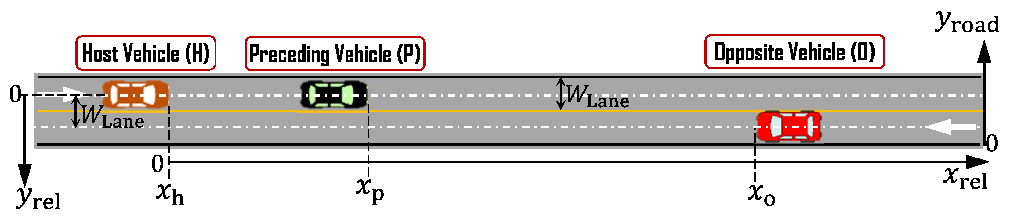
3.1. Overtaking Scenario

Consider a real-world overtaking scenario depicted in Figure 1 (showing the front gate of Gunma University, Kiryu-campus, Japan), where a single-lane curved road has a bus stop. Note that in Japanese tradition of right handed driving, vehicles flow on the left side of the road. Whenever a bus stops for 1–3 min, vehicles behind it have to wait for a while or overtake it safely using the opposite flow lane. On this type of single-lane road, vehicles often need to overtake a slow vehicle by using the opposite lane. However, with an oncoming vehicle on the opposite lane, a driver often fails to make the right decision to initiate the overtake and choose the optimal speeds or trajectories. For simplicity, we use the term Opposite Vehicle (O) to refer to the oncoming vehicle in the opposite lane. Vehicles with fully or partly automated driving systems must also decide and follow the overtaking trajectories for smooth and safe driving on such roads. With the above driving contexts, an optimal overtaking path generation problem is formulated as illustrated in Figure 2, where, with the center-line of the lane (with varying curve) as the reference, the road is represented by straight lanes. We assume that the information of the surrounding traffic is available from the sensor data.

3.2. Modeling of Vehicle Control for Overtaking

We consider any vehicle n { H , P , O } , as shown in Figure 2, with the states ( y n , x n , u n , v n ) , which represent lateral position, longitudinal position, lateral speed, and longitudinal speed, respectively. At a discrete time t with a step size of Δ t , the vehicle’s motion dynamics are as follows:
y n ( t + 1 ) = y n ( t ) + u n ( t ) Δ t , x n ( t + 1 ) = x n ( t ) + v n ( t ) Δ t + 1 2 a n ( t ) Δ t 2 , v n ( t + 1 ) = v n ( t ) + a n ( t ) Δ t ,
where a n is the respective control input representing longitudinal acceleration. Considering the limited magnitude of lateral speed, u n can also be used as the control input for lateral movement. For a safe maneuver over the lanes, it is necessary to determine ( u n ( t ) , a n ( t ) ) for controlling the motion of a vehicle. We assume the host vehicle is equipped with a local controller that perfectly implements the control inputs, i.e., both steering angle control and engine torque control, when the desired overtaking trajectories are provided.

3.3. Overtaking Feasibility Design

Assume that there is no vehicle on the opposite or side lane between the longitudinal distance from the host vehicle to the slow preceding vehicle. In the context of the overtaking planning problem by the host vehicle, for simplicity, the lateral and longitudinal distances of the vehicles are represented by the relative coordinate framework (i.e., the current position of the host vehicle is the origin), as shown in Figure 2. We consider an overtaking maneuver of a host vehicle that starts at the current time t = 0 and finishes at t = T , where t denotes the discrete time with a step size of Δ t . Using the middle of a lane as a reference line, a vehicle should move to the next lane with a limited lateral speed u h , while also traveling at a speed v h along the road. Assume that the vehicle takes t 1 steps to move to the next lane and that the vehicle must maintain a safe gap from its preceding (slow or stopped) vehicle, which can be defined by the following constraint:
x p ( t ) x h ( t ) R 1 , for t = 1 , 2 , , t 1 ,
where x h , x p , and R 1 are the position of the host vehicle, the position of the preceding vehicle, and the constant distance, respectively. The time required for laterally moving the lane width of W Lane at the maximum lateral speed of u max can be used to define the parameter as t 1 = W Lane / ( u max Δ t ) . Similarly, after overtaking, the host vehicle must maintain a minimum gap in front of the preceding vehicle, which can be given as:
x h ( T ) x p ( T ) R 0 + v p t gap ,
where R 0 denotes a constant gap, and t gap is the time gap constant in car-following. The longitudinal speed and acceleration of the host vehicle are regulated by the following constraints:
0 v h ( t ) v max ,
a min a h ( t ) a max ,
where v h and a h are the velocity and acceleration of the host vehicle, and v max , a min , and a max are constants.
As shown in the real example scenario in Figure 1, an overtaking often becomes essential on a curved road, where a vehicle naturally requires lateral speed to keep the same lane. Such required lateral speed for lane-keeping can approximately be estimated using the road angle at any particular point on the road. Therefore, when overtaking on a curved road, a vehicle must move to the next lane in addition to taking into account the curved lanes. Hence, for comfortable overtaking with limited overall lateral movement, the lateral speed should be regulated considering both limits, which is given as:
u min ( t ) u h ( t ) u max ( t ) ,
where u min ( t ) = U comf u ¯ road ( x h ( t ) ) and u max ( t ) = U comf u ¯ road ( x h ( t ) ) represent the minimum and maximum possible lateral speeds, respectively. Considering the symmetry in both ways’ curves for lane-keeping, the same comfortable lateral speed limit U comf is incorporated. The naturally required lateral speed u ¯ road ( t ) for lane-keeping on the curved road is subtracted to obtain the limits of the lateral speed for overtaking as given in (6). Note that, for a straight road, u ¯ road ( x h ( t ) ) = 0 , and the maximum lateral speed for overtaking becomes U comf u max ( t ) U comf . For driving comfort, the lateral acceleration limit while negotiating a curve is usually set to 1.25 m/s2 [19,27], and with limited lateral speed, the maximum acceleration can be kept within that limit. Considering the reference lateral direction (downward) as shown in Figure 2, at the position x h ( t ) , the road angle is θ ( x ( t ) ) . For lane keeping task, the vehicle naturally has a lateral speed of approximately u ¯ h v h ( t ) sin ( θ ( x h ( t ) ) ) . Assuming the standard speed on the road, during the overtake, the corresponding position x h ( t ) of the vehicle and the u ¯ road ( x h ( t ) ) can be estimated in advance. In the case, of a sharp curved road it may be necessary to reduce the speed v h to keep the required u ¯ road ( x h ( t ) ) restricted, whereas, for slightly curved roads (e.g., for the case of Figure 1), the maximum value of u ¯ road ( · ) can be used in (6), for simplicity.
Considering the overtaking decision time t = 0 , the following constraints are also taken into account for a realistic trajectory planning and execution:
u h ( 0 ) = 0 and t = 1 t u h ( t ) Δ t = 0 ,
y h ( t 2 ) = W lane and y h ( T ) = 0 .
According to (7), the lateral movement will only start at t = 1 or later, and the net lateral movement over the period must be zero. Constraints in (8) ensure that the vehicle moves a distance of W lane laterally at t = t 2 and returns to the original lane at the end of overtaking period t = T .
Note that only the aforementioned hard constraints cannot guarantee a collision-free overtake. Furthermore, it is impossible to specify the overtaking-related timings strictly by setting some constraints. Instead, a soft constraint is introduced in terms of a risk penalty to improve safety. In particular, two types of collisions are possible while overtaking: collision with the slow preceding vehicle and collision with the opposite vehicle. Such collisions occur when the relative longitudinal distance between the host and preceding or opposite vehicles is close to zero and they are fully or partially on the same lane. Considering the current lateral position y h ( 0 ) = 0 and lane width W lane , the risk of collision (in a scale of zero to one) at any future time t can be estimated using the relative distance of the vehicle pairs. Specifically, the collision risk with the preceding vehicle is given by:
R HP ( t ) = 1 y h ( t ) W lane e γ ( x p ( t ) x h ( t ) ) 2 ,
where γ is a constant that describes the shape of a Gaussian function. When x p ( t ) x h ( t ) = 0 , the risk will be 1 for y h ( t ) = 0 (both vehicles are on the same lane) and 0 for y h ( t ) = W lane . Similarly, the collision risk with the opposite vehicle is given by:
R HO ( t ) = y h ( t ) W lane e γ ( x o ( t ) x h ( t ) ) 2 ,
where x o is the position of the oncoming vehicle. In this case, the risk will be 1 when y h ( t ) = W lane with the gap x p ( t ) x h ( t ) = 0 . For every safe overtaking, the risk of collision should be close to zero, which can be ensured by introducing a penalty function for high risk as:
P Risk ( t ) = W ( R HP ( t ) + R HO ( t ) ) ,
where W denotes a constant related to the maximum penalty for an expected collision.
In the next section, the optimal overtaking problem is formulated taking into account the above constraints for overtaking feasibility and avoiding collision risk.

3.4. Optimal Overtaking Problem Formulation

The optimal trajectory generating strategy for autonomous vehicle overtaking proposed in this study is based on the solution of an optimal prediction problem with the goal of minimizing driving costs while limiting collision risks in the presence of any opposite vehicle on the overtaking lane. For simplicity, the current position of the host vehicle on the original lane is used as the reference, i.e., x h ( 0 ) = 0 and y h ( 0 ) = 0 , to represent the relative longitudinal positions x p ( 0 ) and x o ( 0 ) of the preceding and opposite vehicles, respectively. We suppose that the slow preceding vehicle and the opposite vehicle will maintain their respective speeds, v p ( 0 ) V road and v o , until t = T . Therefore, the predicted positions x ¯ p ( t ) and x ¯ o ( t ) of the preceding vehicle and opposite vehicle at t = 1 , 2 , , T can be estimated if there are no adjacent obstructing vehicles on the road.
To implement the automated overtaking scheme subject to state dynamics, and feasibility and safety constraints (1)–(11), with given x ¯ p ( t ) , x ¯ o ( t ) , t = 1 , 2 , , T , an optimization problem is solved with the following objective:
min { u h , a h } J ( y h , x h , v h , u h , a h ) = c 1 ( V d v h ( T ) ) 2 + t = 0 T 1 c 2 a h 2 ( t ) + c 3 Δ u h 2 ( t ) + P Risk ( t ) ,
where c 2 , c 2 , and c 3 are constant weights, and Δ u h ( t ) = u h ( t ) u h ( t 1 ) denotes the change in lateral speed in two steps. The first term of the objective function (12) represents the terminal cost, which implies that the vehicle should be close to the desired speed V d at the end of the overtaking. The square of terms associated with acceleration, lateral speed, and change in lateral speed over the period t = 0 , 1 , 2 , , T , are used as the costs in (12) to ensure an efficient and comfortable overtake. By reducing these cost, a vehicle can execute a very smooth overtaking. However, in the presence of a close opposite vehicle, the risk penalty P Risk ( · ) can be significant and dominate the overall cost in (12). The optimal solution would trade off such risk costs by choosing the appropriate control inputs.
The host vehicle can be driven using any car-following scheme (e.g., human driver models, adaptive cruise control, or automated driving), and the necessity of the lane change is assumed to be decided independently when the preceding vehicle is found to be very slow (by some threshold speed level) concerning the usual traffic. In such an event-driven approach, once the host vehicle desires to change lanes, the above scheme can determine the feasibility of lane change and the optimal trajectories, if that exists. Specifically, for any given circumstance, it is necessary to find existence of a feasible solution, either by simple sensory-information-based evaluation (e.g., space unavailability due to the presence of many vehicles) or by the optimization solver. If a feasible solution is not found, the vehicle should remain on the same lane following the slow preceding vehicle using its default driving system. Secondly, if an optimal solution is found, it might be very costly and uncomfortable (e.g., due to the aggressive accelerating and braking to avoid collision risk with the opposite vehicle) and should be avoided. The magnitude of the optimal cost J * can be used to judge such a risky overtake with a suitable threshold. Once the proposed scheme finds a comfortable optimal overtaking solution, the overtaking event starts, and the local controller of the driving system switches to follow the given trajectories.

4. Numerical Simulation

4.1. Simulation Settings

We consider a single-lane both-way road, as shown in Figure 2. The speed limit on the road is 50 km/h and each lane is W lane = 2.5 m wide. The host vehicle and the slow or stopped preceding vehicle are in the left lane, while vehicles in the right lane flow in the opposite direction. The host vehicle is assumed to be 5 m long and 2 m wide. The desired speed v d is set at 50 km/h. A horizon of T = 40 steps (20 s) is considered for the overtake with Δ t = 0.5 s, as a practical overtake does not take more than 20 s [21]. We estimated the curve angle along the road at every 1 m segment. Considering the road center as the reference, the relative maximum change in road curve at each point is found to be about 2.14 , which corresponds to a lateral speed of about 2.05 km/h (considering speed of 55 km/h). Therefore, with U comf = 4 km/h, we consider a flat value of the maximum limit as u max ( · ) = 1.95 km/h and u min ( · ) = 1.95 km/h for the entire horizon. The maximum longitudinal speed V max is set at 60 km/h. The minimum time steps t 1 of (2) required to move to the next lane is estimated to be 10 steps, whereas t 2 of (8) is set at 14 steps (a few steps higher than t 1 ). Parameters R 0 , R 1 , and t gap are set at 8 m, 4 m, and 1.0 s, respectively. The parameters related to risk penalties (10) and (11) are γ = 0.02 and W = 200 . The weight constants in the objective function (12) are set as c 1 = 50 , c 2 = 20 , and c 3 = 20 . With these simulation settings, the proposed overtaking trajectory optimization problem is solved using the MATLAB Nonlinear Optimization Toolbox for evaluation in several driving scenarios considering limited road curves as described above. Figure 3 depicts the flow chart for implementing the proposed scheme, including the generation of the optimal overtaking trajectory. A vehicle must follow the (curved) lane according to the reference lane-following trajectories in usual driving. Once it detects the necessity of overtaking and obtains a feasible solution, the driving mode is changed to overtaking mode. During the overtaking mode, the vehicle follows the trajectories generated by the proposed scheme. Upon completion of overtaking, the driving mode changes to lane-following mode.

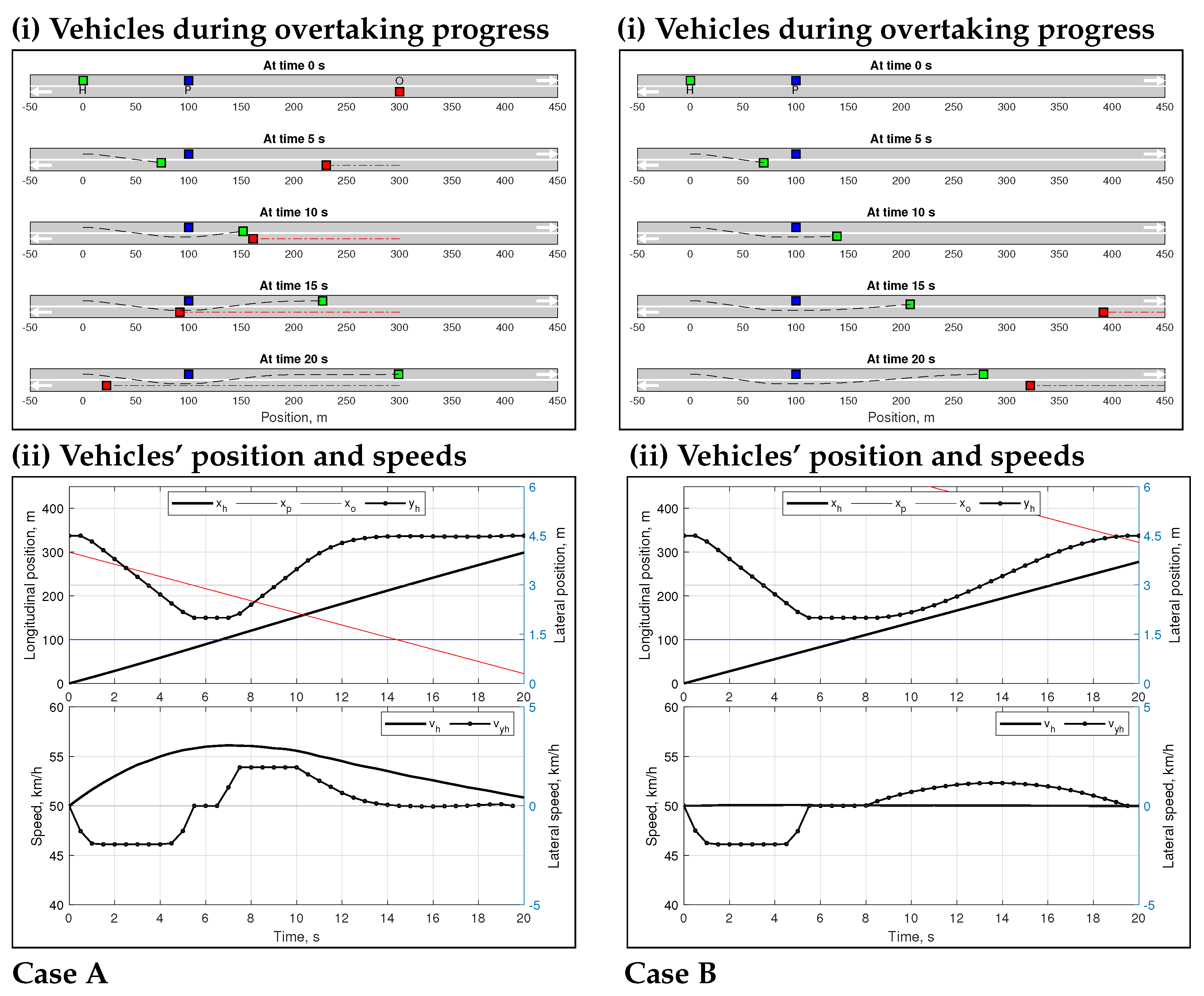
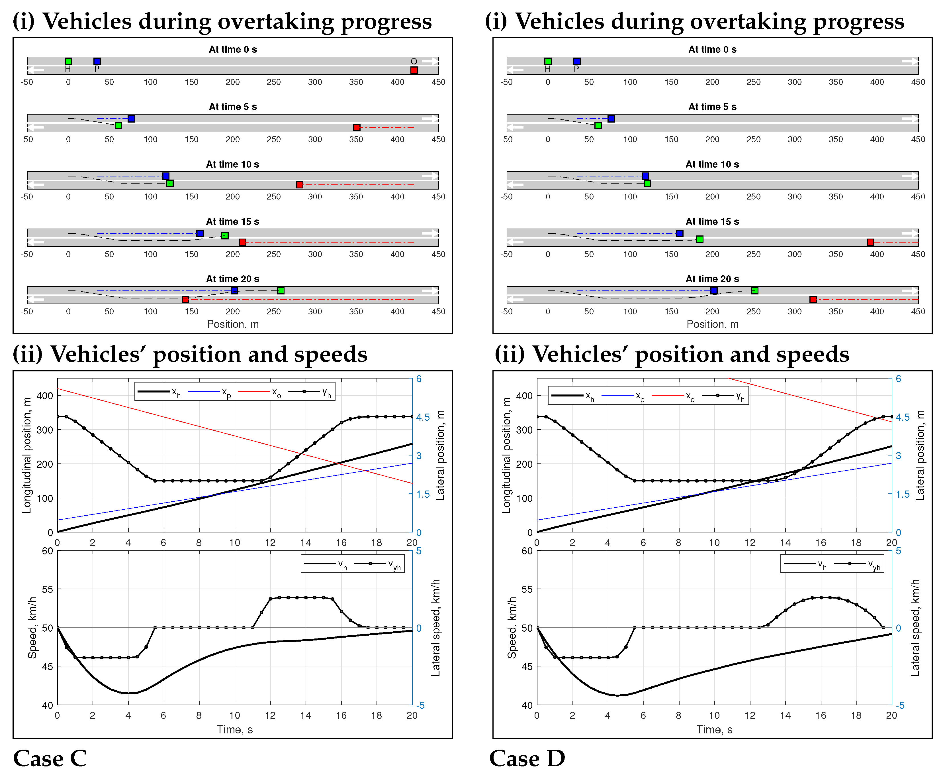
4.2. Optimal Overtaking Trajectories

We start by analyzing typical overtaking scenarios and optimizing the overtaking trajectories of the host vehicle. Specifically, we observe the optimal overtaking solution for four different cases based on the speed of the preceding vehicle (before the overtake) and the position of the opposite vehicle. In the context of a stopped vehicle in front, the optimal overtaking solution is obtained with and without the presence of an approaching vehicle, as illustrated in Figure 4. In Case A of Figure 4, the host vehicle, traveling at 50 km/h, is initially 100 m behind the stopped vehicle, i.e., in this case, overtaking is mandatory. However, overtaking becomes difficult due to the presence of an opposite vehicle at 300 m away traveling at 50 km/h. It is found that the optimal overtaking scheme ensures a smooth and safe overtake in this challenging situation with limited lateral speed imposed by the road curves. The host vehicle speeds up to about 56 km/h, entirely placing itself in the next lane while parallel to the stopped vehicle (at about 6 s), and then returning to the original lane at about 150 m, critically avoiding the opposite vehicle (at about 14 s). When the host vehicle becomes parallel to the opposite vehicle, it can completely place itself in the original lane. In Case B of Figure 4, overtaking is easier, when the opposite vehicle is far away. In this case, the host vehicle maintains a nearly constant speed of 50 km/h and returns to the original lane smoothly.
Figure 5 depicts overtaking scenarios in which the preceding vehicle is traveling at a slower speed than the normal traffic speed on the road, implying that the overtaking will take longer. Specifically, the preceding vehicle is traveling at a speed of 30 km/h and is initially located about 35 m ahead. In Case C of Figure 5, the optimal overtaking trajectory is shown when the opposite vehicle is 430 m away and traveling at 50 km/h. In this case, the difficulty of overtaking is significant since the host vehicle is already close behind the preceding vehicle. It must slow down first to shift to the next lane with limited lateral speed to avoid a rear-end collision and complete the overtake before colliding with the opposite vehicle. The simulation result shows that the host vehicle slows initially before moving completely to the adjacent lane in about 5.5 s. Remaining in the overtaking lane, it completely overtakes the vehicle while keeping the required safe lateral distance (about 11 s) before returning to the original lane. Remarkably, during overtaking, it gradually speeds up instead of aggressively accelerating, and with appropriate timing (using the maximum lateral speed limit), it can avoid the risk of collision with the opposite vehicle. Although a 20 s horizon is considered, depending on the driving context, the vehicle could return to the original lane much earlier, at around 17 s. Note that due to the curved road with the maximum lateral speed being restricted, the host vehicle takes a long time to move to the next lane and has to reduce its longitudinal speed to avoid a collision. In the case of a straight road with a higher lateral speed limit, the vehicle would not drop its speed much, and a slightly faster overtake could be expected.
In Case D of Figure 5, the opposite vehicle is far away and has no effect on the overtaking maneuver. Therefore, the host vehicle avoids a quick return to the original lane by staying on the adjacent lane for 12.5 s and maintaining smooth lateral movement. The final speed is slightly less than 50 km/h because there is no constraint to have it be 50 km/h, except for a terminal cost in the objective function. However, such a speed difference at the end and a drop in speed at the beginning could be avoided if the host vehicle could begin overtaking with a wider initial gap, assuming that other vehicles in the overtaking lane were unavailable. Note that both Figure 4 and Figure 5 show scenarios with arbitrary initial vehicle speeds and positions in order to evaluate the capability of the proposed optimal trajectory generation scheme. The results show that the scheme can generate the optimal overtaking path in any feasible scenario. However, even if a vehicle could execute an overtake by barely avoiding a collision, it is usually not desirable due to the high costs involved. Furthermore, for proper driving systems, it is necessary to determine the best point to initiate an overtaking. Even if an overtake is possible, depending on the risks or costs, it may be avoided.

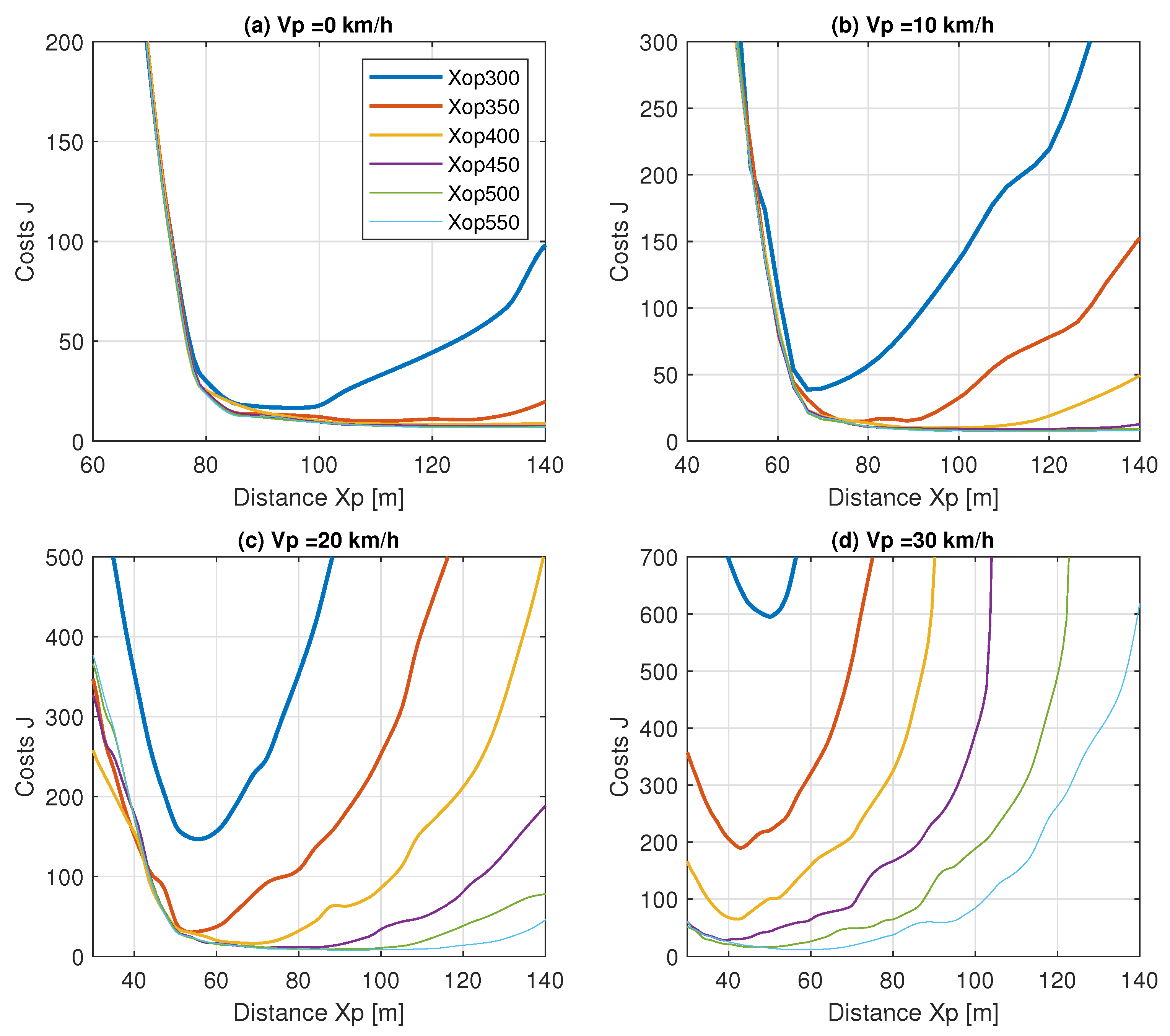
4.3. Optimal Overtaking Costs

In view of the aforementioned considerations, it is necessary to investigate the optimal overtaking states, as well as the associated overall costs. To investigate that, at first we observe the behavior of the host vehicle as it approaches a slower or overtaking vehicle. In particular, if the host vehicle is unable to initiate an overtake and must approach the slow vehicle, the distance and speed of the host vehicle are observed for various speed conditions of the slow vehicle. Figure 6 depicts the distance–speed curves in four scenarios where the preceding vehicle is traveling at 0 km/h, 10 km/h, 20 km/h, and 30 km/h, while the usual road speed is 50 km/h. This behavior is obtained using the intelligent driver model (IDM) [28], with typical parameters.
Finally, the overall cost of overtaking is observed in varying situations with respect to the distance of the opposite vehicle, as shown in Figure 7, by considering various driving states, i.e., distance to the preceding vehicle and related speed. Figure 7a demonstrates the case where the preceding vehicle is idling on the lane ( V p = 0 ) . For a particular distance ( X o p ) between the preceding and opposite vehicles, the cost J (12) for the overtaking period is evaluated. It shows that when the host vehicle is less than 80 m away from the idle vehicle, the costs increase significantly. Being close behind, the idling vehicle and slowing down causes the host vehicle to incur costs due to speed deviation and necessary acceleration, regardless of the distance of the opposite vehicle. Unless the opposite vehicle is very close, e.g., 300 m, and the overtaking is initiated from about 120 m to 140 m, the cost is minimal. Even if it is impossible to initiate the overtake in a timely manner due to the presence of a vehicle in the other lane, initiating at some closer distance of around 80 to 120 m will incur a marginal cost increase. However, for the case when the opposite vehicle is only about 300 m from the preceding vehicle, the optimal distance to overtake is between about 90 m and 100 m. To avoid collision with the opposite vehicle, a larger gap would necessitate an increase in speed and aggressive acceleration. Hence, the cost curve becomes U-shaped for this scenario.
Figure 7b–d show the overtaking costs for the preceding vehicle speeds V p of 10 km/h, 20 km/h, and 30 km/h, respectively. In any case, the overtaking cost increases as the speed of the preceding vehicle increases. However, the costs vary greatly depending on the distance of the opposite vehicle. Most interestingly, the cost characteristics become a U-shaped curve in respect to the distance of the preceding vehicle. Therefore, the minimum cost point for each scenario is distinct and easily identifiable. Nevertheless, some overtaking can be costly and dangerous because the host vehicle must complete the maneuver quickly with high acceleration and speed before colliding with the opposite vehicle. The high cost at the optimal point, e.g., as found in Figure 7c,d for X o p 300 , is mostly due to the compromise of collision risks. In addition to the costs of collision risk in part, the overtaking solution with high costs implies considerable speed variation with aggressive acceleration and braking, which causes extra fuel consumption and emissions. Therefore, the proposed scheme could contribute to transportation sustainability by promoting the best timing to initiate a least-cost overtaking maneuver with optimal trajectories.

5. Discussion

The majority of research on autonomous overtaking has been conducted on multi-lane roads, treating it as a static or moving obstacle avoidance problem without taking into account any opposite vehicles. However, single-lane overtaking is a regular scenario in the real world in which a vehicle must cross the opposite lane, and overtaking becomes more difficult and dangerous when a fast approaching vehicle is present. Furthermore, prior research has primarily focused on overtaking on straight roads, with no guarantee that it will work on a curved road. As a promising solution to this problem, we develop in this paper a novel optimal trajectory generation scheme for autonomous overtaking in a smooth and safe manner on a single-lane road. We consider different road constraints, opposite vehicles, and slow or stopped preceding vehicles in the optimization process. Moreover, we obtain the optimal overtaking costs for various states of the surrounding traffic.
The proposed scheme has some limitations, e.g., it requires perfect information of surrounding traffic, and traffic flow uncertainties or randomness are not considered in the optimization process. Although the scheme can generate optimal trajectories in critical cases, any risky overtaking in an uncertain situation with the opposite vehicle should be made by an extra safety margin. Overtaking in such an uncertain situation can be handled efficiently by adequately tuning the parameters associated with the scheme based on the types and levels of uncertainty. If the associated vehicles are connected–automated, V2V communication can be employed to have precise information instead of onboard sensors to overcome traffic uncertainty and randomness. Furthermore, under a complete cyber-physical coordination framework, e.g., [29], the proposed overtaking scheme can be employed for coordinating vehicles in dense traffic with lane blockage situations for smooth traffic flows. Such research could be a fascinating continuation of this work.

6. Conclusions

In this paper, we have developed a novel optimal trajectory generation scheme for autonomous vehicle overtaking to avoid different moving obstacles or vehicles in order to ensure driving safety and efficiency. The proposed scheme is based on solving an optimal prediction problem with the goal of minimizing driving costs while eliminating collision risks in the presence of any opposite vehicle on the overtaking lane. The scheme is applicable to both straight and curved roadways, and can be implemented in real-time. The scheme is tested on a real single-lane curved road, with stopped and slow vehicles in the lane, as well as the presence or absence of a vehicle in the opposite lane. The findings show that the proposed scheme is effective at both lane keeping and changing lanes successfully while overtaking. The optimal overtaking trajectories determined for various conditions of the associated vehicles show that the best overtaking state to initiate an overtaking maneuver in the course of driving can be identified from the obtained cost characteristics.
In contrast to the existing overtaking schemes found in the recent literature, the proposed overtaking scheme can be incorporated with any driving system for providing smooth and safe overtaking trajectories over the opposite lane despite road curves and the presence of the opposite vehicle according to the illustrated simulation results. The proposed system can be employed as either a fully automated or advanced driver assistance system (ADAS). In the perspective of the forthcoming automotive revolution on connected–automated driving, the proposed scheme can be further enhanced to develop a cooperative driving scheme. The proposed optimal overtaking scheme is expected to play an essential role in enhancing transportation sustainability by smoothing traffic flows and alleviating the adverse effects of traffic bottlenecks in challenging driving scenarios addressed in this study. In future work, the scheme will be extended for cooperative overtaking maneuver in a dense traffic conditions using inter-vehicle communication technology.

Author Contributions

Conceptualization, Y.Y., A.S.M.B. and M.A.S.K.; methodology, Y.Y., A.S.M.B. and M.A.S.K.; validation, K.H. and M.A.S.K.; formal analysis, Y.Y., A.S.M.B. and M.A.S.K.; investigation, K.H., M.A.S.K. and K.Y.; data curation, Y.Y. and M.A.S.K.; writing—original draft preparation, Y.Y.; writing—review and editing, A.S.M.B., K.H., M.A.S.K. and K.Y.; visualization, Y.Y. and M.A.S.K.; supervision, A.S.M.B., K.H., M.A.S.K. and K.Y.; project administration, K.H., M.A.S.K. and K.Y. All authors have read and agreed to the published version of the manuscript.

Funding

This research is supported by the Japan Society for the Promotion of Science (JSPS) Grant-in-Aids for Scientific Research (C) 20K04531.

Institutional Review Board Statement

Not applicable.

Informed Consent Statement

Not applicable.

Data Availability Statement

Not applicable.

Conflicts of Interest

The authors declare no conflict of interest. The funders had no role in the design of the study; in the collection, analyses or interpretation of data; in the writing of the manuscript, or in the decision to publish the results.

References

  1. National Highway Traffic Safety Administration (NHTSA). Traffic Safety Facts: Summary of Motor Vehicle Crashes; DOT HS 813 209; US Department of Transportation: Washington, DC, USA, 2019.
  2. World Health Organization (WHO). Road Traffic Injuries; WHO: Geneva, Switzerland, 2021; Available online: https://www.who.int/news-room/fact-sheets/detail/road-traffic-injuries (accessed on 12 December 2021).
  3. National Highway Traffic Safety Administration (NHTSA). Traffic Safety Facts: Critical Reasons for Crashes Investigated in the National Motor Vehicle Crash Causation Survey; DOT HS 812 115; US Department of Transportation: Washington, DC, USA, 2015.
  4. Hegeman, G.; van der Horst, R.; Brookhuis, K.; Hoogendoorn, S. Functioning and acceptance of overtaking assistant design tested in driving simulator experiment. Transp. Res. Rec. 2007, 2018, 45–52. [Google Scholar] [CrossRef]
  5. Dimitrakopoulos, G.; Demestichas, P. Intelligent transportation systems. IEEE Veh. Technol. Mag. 2010, 5, 77–84. [Google Scholar] [CrossRef]
  6. Wei, S.; Zou, Y.; Zhang, X.; Zhang, T.; Li, X. An integrated longitudinal and lateral vehicle following control system with radar and vehicle-to-vehicle communication. IEEE Trans. Veh. Technol. 2019, 68, 1116–1127. [Google Scholar] [CrossRef]
  7. Ulbrich, S.; Maurer, M. Probabilistic online POMDP decision making for lane changes in fully automated driving. In Proceedings of the IEEE International Conference on Intelligent Transportation Systems (ITSC), Hague, The Netherlands, 6–9 October 2013; pp. 2063–2070. [Google Scholar]
  8. You, F.; Zhang, R.; Lie, G.; Wang, H.; Wen, H.; Xu, J. Trajectory planning and tracking control for autonomous lane change maneuver based on the cooperative vehicle infrastructure system. Expert Syst. Appl. 2015, 42, 5932–5946. [Google Scholar] [CrossRef]
  9. Bakibillah, A.S.M.; Kamal, M.A.S.; Tan, C.P.; Susilawati, S.; Hayakawa, T.; Imura, J.I. Bi-Level coordinated merging of connected and automated vehicles at roundabouts. Sensors 2021, 21, 6533. [Google Scholar] [CrossRef]
  10. Andersen, H.; Schwarting, W.; Naser, F.; Eng, Y.H.; Ang, M.H.; Rus, D.; Alonso-Mora, J. Trajectory optimization for autonomous overtaking with visibility maximization. In Proceedings of the IEEE 20th International Conference on Intelligent Transportation Systems (ITSC), Yokohama, Japan, 16–19 October 2017; pp. 1–8. [Google Scholar]
  11. Naranjo, J.E.; Sotelo, M.A.; Gonzalez, C.; Garcia, R.; De Pedro, T. Using fuzzy logic in automated vehicle control. IEEE Intell. Syst. 2007, 22, 36–45. [Google Scholar] [CrossRef]
  12. Vlahogianni, E.I. Modeling duration of overtaking in two lane highways. Transp. Res. Part F Traffic Psychol. Behav. 2013, 20, 135–146. [Google Scholar] [CrossRef]
  13. Hegeman, G.; Brookhuis, K.; Hoogendoorn, S. Opportunities of advanced driver assistance systems towards overtaking. Eur. J. Transp. Infrastruct. Res. 2005, 5, 1–16. [Google Scholar]
  14. Vanholme, B.; Gruyer, D.; Lusetti, B.; Glaser, S.; Mammar, S. Highly automated driving on highways based on legal safety. IEEE Trans. Intell. Transp. Syst. 2012, 14, 333–347. [Google Scholar] [CrossRef]
  15. Petrov, P.; Nashashibi, F. Modeling and nonlinear adaptive control for autonomous vehicle overtaking. IEEE Trans. Intell. Transp. Syst. 2014, 15, 1643–1656. [Google Scholar] [CrossRef] [Green Version]
  16. Dixit, S.; Montanaro, U.; Dianati, M.; Oxtoby, D.; Mizutani, T.; Mouzakitis, A.; Fallah, S. Trajectory planning for autonomous high-speed overtaking in structured environments using robust MPC. IEEE Trans. Intell. Transp. Syst. 2019, 21, 2310–2323. [Google Scholar] [CrossRef]
  17. Shamir, T. How should an autonomous vehicle overtake a slower moving vehicle: Design and analysis of an optimal trajectory. IEEE Trans. Autom. Control 2004, 49, 607–610. [Google Scholar] [CrossRef]
  18. Baber, J.; Kolodko, J.; Noel, T.; Parent, M.; Vlacic, L. Cooperative autonomous driving: Intelligent vehicles sharing city roads. IEEE Robot. Autom. Mag. 2005, 12, 44–49. [Google Scholar] [CrossRef] [Green Version]
  19. Usman, G.; Kunwar, F. Autonomous vehicle overtaking-an online solution. In Proceedings of the IEEE International Conference on Automation and Logistics, Shenyang, China, 5–7 August 2009; pp. 596–601. [Google Scholar]
  20. Naranjo, J.E.; Gonzalez, C.; Garcia, R.; De Pedro, T. Lane-change fuzzy control in autonomous vehicles for the overtaking maneuver. IEEE Trans. Intell. Transp. Syst. 2008, 9, 438–450. [Google Scholar] [CrossRef] [Green Version]
  21. Milanés, V.; Llorca, D.F.; Villagrá, J.; Pérez, J.; Fernández, C.; Parra, I.; González, C.; Sotelo, M.A. Intelligent automatic overtaking system using vision for vehicle detection. Expert Syst. Appl. 2012, 39, 3362–3373. [Google Scholar] [CrossRef] [Green Version]
  22. Ngai, D.C.K.; Yung, N.H.C. A multiple-goal reinforcement learning method for complex vehicle overtaking maneuvers. IEEE Trans. Intell. Transp. Syst. 2011, 12, 509–522. [Google Scholar] [CrossRef] [Green Version]
  23. Wang, F.; Yang, M.; Yang, R. Conflict-probability-estimation-based overtaking for intelligent vehicles. IEEE Trans. Intell. Transp. Syst. 2009, 10, 366–370. [Google Scholar] [CrossRef] [Green Version]
  24. Lattarulo, R.; Pérez Rastelli, J. A hybrid planning approach based on MPC and parametric curves for overtaking maneuvers. Sensors 2021, 21, 595. [Google Scholar] [CrossRef]
  25. Shackel, S.C.; Parkin, J. Influence of road markings, lane widths and driver behaviour on proximity and speed of vehicles overtaking cyclists. Accid. Anal. Prev. 2014, 73, 100–108. [Google Scholar] [CrossRef]
  26. Bentaleb, K.; Lakouari, N.; Marzoug, R.; Ez-Zahraouy, H.; Benyoussef, A. Simulation study of traffic car accidents in single-lane highway. Phys. A Stat. Mech. Appl. 2014, 413, 473–480. [Google Scholar] [CrossRef]
  27. Tan, H.S.; Guldner, J.; Patwardhan, S.; Chen, C.; Bougler, B. Development of an automated steering vehicle based on roadway magnets-a case study of mechatronic system design. IEEE/ASME Trans. Mechatron. 1999, 4, 258–272. [Google Scholar]
  28. Kesting, A.; Treiber, M.; Helbing, D. Enhanced intelligent driver model to access the impact of driving strategies on traffic capacity. Philos. Trans. R. Soc. Math. Phys. Eng. Sci. 2010, 368, 4585–4605. [Google Scholar] [CrossRef] [PubMed] [Green Version]
  29. Kamal, M.A.S.; Tan, C.P.; Hayakawa, T.; Shun-Ichi, A.; Imura, J.I. Control of Vehicular Traffic at an Intersection Using a Cyber-Physical Multiagent Framework. IEEE Trans. Ind. Inform. 2021, 17, 6230–6240. [Google Scholar] [CrossRef]
Figure 1. An overtaking scenario based on traffic conditions of a real single-lane road, as depicted using the Map, with the front gate of Gunma University, Kiryu-campus, Japan.
Sustainability 14 01807 g001
Figure 2. An overtaking problem of a host vehicle (H) with its original preceding vehicle (P) and an oncoming vehicle in the opposite lane (opposite vehicle). With the host vehicle’s position x h as the origin, the positive lateral axis y rel is given according to the direction of the overtaking lane.
Sustainability 14 01807 g002
Figure 3. Flow chart of the proposed optimal trajectory generation scheme for autonomous overtaking in the driving framework.
Sustainability 14 01807 g003
Figure 4. Two overtaking cases with preceding (P) vehicle with zero speed: (Case A) encountering an opposite vehicle (O) and (Case B) with a far opposite vehicle. In each case, (i) the vehicles’ positions are shown at each 5 s during the overtaking course, and (ii) both longitudinal and lateral positions and speeds of the vehicles are illustrated using trajectories.
Sustainability 14 01807 g004
Figure 5. Two overtaking cases in a difficult scenario due to the non-zero speed of the P vehicle: (Case C) encountering an opposite car (O) and (Case D) without a nearby opposite car. In each case, (i) the vehicles’ positions are shown at each 5 s during the overtaking course, and (ii) both longitudinal and lateral positions and speeds of the vehicles are illustrated using curves over time.
Sustainability 14 01807 g005
Figure 6. The speed of the host vehicle when approaching a slow preceding vehicle before attempting for lane change or overtake.
Sustainability 14 01807 g006
Figure 7. The overtaking costs with respect to the initial distance X p to the slow preceding vehicle for various longitudinal gaps X o p between the preceding and opposite vehicles and speed of the preceding vehicle V p . Legend is only shown in (a), for simplicity.
Sustainability 14 01807 g007
Publisher’s Note: MDPI stays neutral with regard to jurisdictional claims in published maps and institutional affiliations.

