Article

Combination Layout of Traffic Signs and Markings of Expressway Tunnel Entrance Sections: A Driving Simulator Study

1
School of Urban Rail Transportation, Shanghai University of Engineering Science, Shanghai 201620, China
2
Transportation Safety Research Center, China Academy of Transportation Sciences, Beijing 100029, China
3
Shanghai Municipal Engineering Design and Research Institute (Group) Co., Ltd., Shanghai 200092, China
*
Author to whom correspondence should be addressed.
Sustainability 2022, 14(6), 3377; https://doi.org/10.3390/su14063377
Submission received: 29 November 2021 / Revised: 6 March 2022 / Accepted: 10 March 2022 / Published: 14 March 2022

Abstract

:
To determine a better combination of signs and markings on expressway tunnel entrance sections, three types of typical signs and markings were compared and tested according to five indicators: speed, lane lateral offset, lane change behavior, fixation behavior, and operating load, using a driving simulator. The results identified that the obvious no overtaking and speed limit signs, combined with a layer of thin red pavement, had the most influence on drivers’ speed, and they led to the highest fixation frequency of static facilities, the longest average distance from the completion point of the lane change to the entrance, and the longest average lane change distance, which could help drivers to pass through tunnel entrance sections more smoothly. The location of the static facilities should be between 3 s before the tunnel entrance and 3 s after entering the tunnel, as this is the area where a driver’s relative viewpoint changes. The improper combination of warning signs and deceleration measures will affect a driver’s judgment, causing negative effects, such as premature lane changes and an increased operating load. The research results can provide a design basis and reference for the combination setting of safety signs and markings on tunnel entrance sections.

1. Introduction

According to the existing statistics of traffic accidents in highway tunnel sections in mountainous areas, the traffic accident rate in highway tunnel sections in China is slightly higher than that of general open roads [1]. Tunnel entrance sections have always been considered a bottleneck by traffic safety management, and their safety designs are very important to reduce traffic accidents and traffic congestion caused by accidents. Amundsen pointed out that traffic accidents in bridge and tunnel sections are mainly concentrated in two parts: 50 m before the tunnel and 150 m after entering the tunnel, accounting for about 75% of the total accident rate [2]. Beard summarized three safety characteristics of European tunnels. The tunnel accident rate is slightly lower than that of general open roads, the area near the entrance section is more dangerous than that of the middle section, and non-fire accidents are far more common than fire accidents [3]. Statistics of tunnel accidents in China show that the relatively high traffic accident rate in tunnel entrance sections is mainly due to the transition between two different operating environments in tunnel entrance sections. That is to say, the differences in alignment, skid resistance, lighting and climate environment have a great impact on driving safety [1,4]. The question of how to improve the operating environment of tunnel entrance sections mainly depends on how to provide accurate tunnel entrance information for drivers, so it is very important to use and set up marking lines.
Due to the limitations of route selection in mountainous areas of China, there are a certain number of road sections at the entrance of tunnels that need to set up corresponding signs and marks to remind and warn drivers. For the traffic static facilities at the entrances of tunnels, the Chinese code mainly stipulates the setting requirements of tunnel information signs. The signs and lines used in actual projects vary greatly, and the results are mixed. Therefore, this paper conducts a comparative test for three typical combinations of signs and marks, and analyzes the combination setting method of signs and marks for the entrance sections of expressway tunnels in mountainous areas.

2. Literature Overview

2.1. Studies on Types of Traffic Signs and Markings

Research has been done on the influence of different types of traffic signs and road markings on driving safety [5,6,7]. Studies of the effects of traffic signs and markings on driving safety have largely focused on warning signs, road markings and rumble strips. Many scholars have also carried out research on the positions of traffic signs and markings, and have also focused on speed [6,8,9,10]. Vest A. et al. evaluated the use of several warning signs and pavement markings at problematic rural horizontal curves, and also evaluated their effectiveness in relation to speed reduction [6]. Ding Han proposed an index of relative speed differences to evaluate the effectiveness of speed reduction markings [8]. Zhao found that the positions of curve warning signs had a statistically significant effect on drivers’ average speed [9]. Shinta et al. found that the absence of traffic signs and road markings resulted in an increase in accidents through the observation of traffic signs and road markings, and compared these with the regulations of the Ministry of Transportation for road signs and markings [10].
In addition, research has been carried out on the design of traffic signs based on the principles of ergonomics [11,12]. Shinar D. evaluated the comprehension of traffic signs in four different countries, finding that comprehension levels vary widely and that they are apparently related to the extent that sign designs incorporate ergonomic guidelines for good design [11]. Ben-Bassat T tested the relationship between the comprehension probability of expressway signs and the extent to which they comply with three ergonomic principles of design: sign–content compatibility, familiarity, and standardization [12]. In another study, the effects of driver factors and sign design features were addressed through evaluating the comprehensibility of traffic signs [13]. To evaluate the benefits of text and symbolic displays in expressway signs relative to their familiarity and effects on comprehension speed and accuracy, an alternative to existing unfamiliar symbolic signs was tested through studying the effect of adding text [14].

2.2. Studies on Driving Simulators Used to Assess Safety

It has been found that using driving simulators to design and set traffic signs is effective [15,16,17,18,19]. Yan et al., through a driving simulator experiment, found that it is better to place the variable information board 150–200 m upstream from the accident, and that using display images on the variable information board is more advisable than just displaying text [15]. Godley verified the effectiveness of the stationary driving simulator. By comparing the experiments in virtual and real scenes, it was found that a driving simulator with the driving speed as the evaluation index was relatively effective under the conditions of vibration deceleration markings and deceleration signs [16]. Similarly, Jamson concluded that driving simulators can be applied to the evaluation of road safety facilities on the basis of studying the effectiveness of different deceleration control measures [17].
Most of the existing studies on the design of signs and markings for tunnel entrances focus on the location of signs and markings [20] and on speed limits [21]. Drivers are influenced by the combination of signs and lines in actual driving [22]. This paper focuses on the use of different combinations of signs and marks, and compares these different combinations; the conclusion should be of practical significance. Therefore, a driving simulation test was conducted on the combination setting of multi-group signs and marks at the entrance of a tunnel, and an index system is proposed to characterize the combination setting of the driving simulation’s signs and marks. On the basis of the experimental results, this paper offers guidance for the combination setting of tunnel entrance signs and markings.

3. Methods

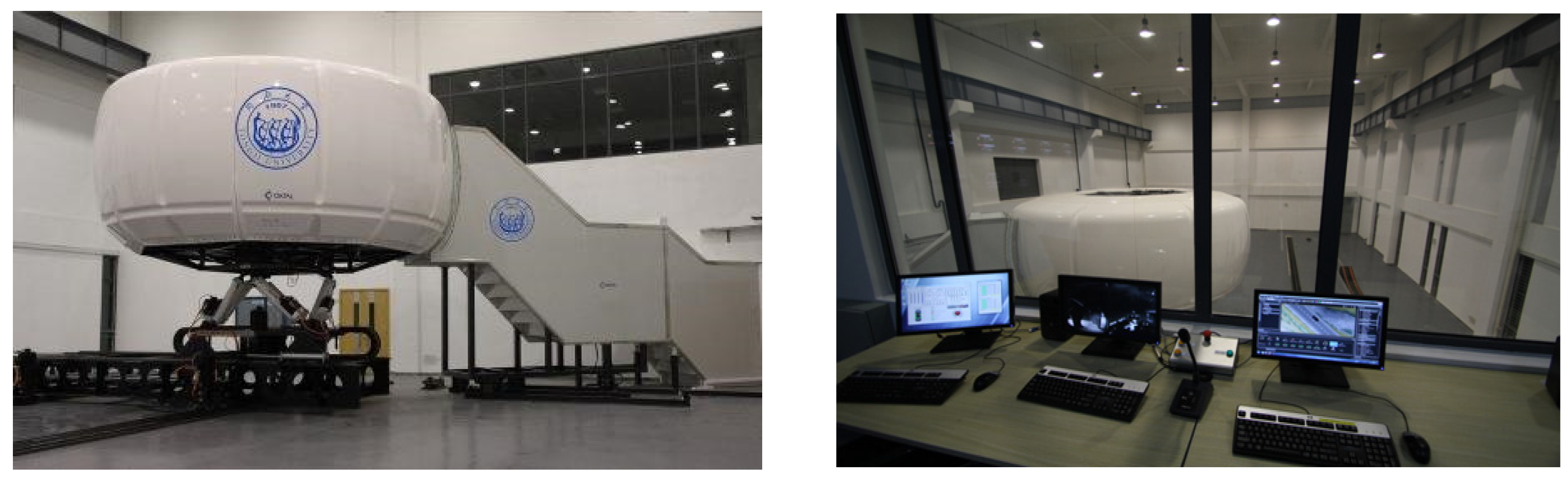
3.1. Driving Simulator

The experiment used Tongji University’s 8-DOF driving simulation platform, and the platform was equipped with SCANeR™ studio software, as shown in Figure 1, which simulated a driving scene with a refresh rate of 60 Hz through five projectors with a resolution of 1000 × 1050, and the perspective could reach 250° × 40°. The experimenter was in a full-sized MEGANA III car cab, and all dynamic feedback was provided by an 8-DOF power system under the cab. The platform collected data at a frequency of 20 Hz.

3.2. Experimental Design

The tunnel entrance section was provided with different combinations of static facilities, and the drivers’ behaviors were also different. The experiment studied the influence of different static facilities on the drivers, from changes in driving characteristics to drivers’ psychological and physiological indicators, and determined the optimal combination of static facilities for the tunnel entrance section.
The length of the experimental section was about 6 km, the length of the tunnel on the section was 680 m, the bridge section was 800 m, the design speed of the entire line was 80 km/h, the lane width was 3.75 m, the marking width was 0.15 m, and the emergency lane width was 2.5 m. In order to minimize the impact of alignment on the visual signs and markings, a flat slope was adopted for the profile. The minimum radius of the circular curve was 1000 m. The alignment superelevation and structure of signs met the requirements of Chinese specifications. The experimental scene was selected under the conditions of good climate and low traffic density.
The experimental road scene is shown in Figure 2 and Figure 3.
According to the field investigation, the common static safety facilities in bridge tunnel transition sections include the tunnel portal elevation mark, tunnel name, tunnel name sign, color thin-layer pavement, no overtaking sign, please turn on the headlights sign when entering the tunnel, ground speed limit sign and transverse deceleration mark. In this experiment, three typical static facility combination settings were selected for the experiment, and the impact of different static facility settings on the safety of drivers was analyzed. Table 1 shows the comparison scheme of static facility settings for the bridge–tunnel transition section. (In the following, combination 1, combination 2 and combination 3 are represented by ZH 1, ZH 2 and ZH 3, respectively. In addition, as this study is aimed at Chinese highway tunnels, the target drivers are mainly Chinese, so the experimental tunnel signs are designed in Chinese).

3.3. Participants

To ensure that the experimental results of the driving simulation of the tunnel entrance sections were not affected by other uncertain factors, it was ensured that the test drivers were fully rested before the driving simulation. Before the experiment, the researchers conducted simple training for the test drivers to ensure that they fully understood the use procedures of the driving simulator, and then the eye tracker was installed and debugged. Before the official driving simulation experiment, a transitional section of about 5 min was set up to ensure that the test driver fully adapted to the foggy driving simulation scene. In the subsequent formal driving simulation experiment, the researchers communicated with the test driver through communication equipment installed in the driving simulator. The experiment recruited 10 drivers over the age of 23, with an average age of 32.6 and a standard deviation of 4.5 recorded. All 10 drivers had average driving experience of 7.3 years, with a standard deviation of 2.54 years recorded. All 10 drivers were in good health, had adequate sleep, did not drink alcohol, had a driving license (Chinese C1 license) and had a cumulative mileage of more than 100,000 km.

3.4. Experimental Procedure

In order to avoid the influence of the driver on the operation proficiency of the simulator, the driver operated the simulator in the scene of the simulator for 20 min. During the formal test, ZH 1~ZH 3 scenes were played randomly, and each tested driver traversed three scenes.

3.5. Data Analysis Method

The test output data were divided into two parts: the data output by the driving simulator (including time, stake number, speed, acceleration, vehicle lateral offset, steering wheel angle coefficient, etc.) and the eye movement data output by the eye tracker (including eye status, fixation location, etc.). The comparative analysis of the data mainly used SPSS and MATLAB software. The data that met the normal distribution were tested by analysis of variance, and the data that did not meet the normal distribution were tested by non-parametric testing.

4. Results

4.1. Driving Characteristics

4.1.1. Speed Indicator

Speed is an important indicator affecting road safety. In the study, sections of the tunnel were intercepted every 100 m from K0 + 600 to K1 + 700, as shown in Figure 4. The speeds of all drivers in each section were counted, and a box plot of the speed distribution of these 10 sections was drawn, which is shown in Figure 5. In the ZH 2 scenario, the overall speed of the drivers did not change significantly, and the dispersion of the driving speed of different drivers in each section was also significantly smaller than those of the other two scenarios. In the ZH 3 scenario, the horizontal deceleration marking and the speed limit on the road had an effect on the speed of some drivers (the average speed of combination three before the tunnel entrance was lower than that of combination one, but the 85% speed performance was not consistent).
To further confirm the relationship between the speed and its related statistics in the three schemes, SPSS software was used to test whether the different combinations of static facilities had a significant impact on the section average speed, 85-bit speed, and standard deviation using the analysis of variance. According to the test results in SPSS, none of the above values met the normal distribution test. Therefore, a non-parametric test method was used for analysis. Friedman’s two-way analysis of variance showed that the average ranks were 3.0, 1.4 and 1.6, χ2 = 15.2, and p = 0.001, and Kendall’s harmony coefficient test showed that the average ranks were 3.0, 1.4, and 1.6 and that the harmony coefficient W = 0.760, χ2 = 15.2, and p = 0.001. The results showed that the three different combinations of static facilities each had a significant effect on the section average speed.
According to the test ranking, it was found that the average speed in the ZH 1 scheme was higher than that of ZH 2 and ZH 3. The 85-bit speed and standard deviation of the speed of each section were tested further. The standard deviation of ZH 2 and the standard deviation of speed were the smallest. ZH 1 and ZH 3 performed basically the same for the section 85-bit speed and the standard deviation of section speed. The advantages of ZH 3 were not obvious, as Table 2 shows.

4.1.2. Lane Offset Indicators

Figure 6 shows the lateral offsets under the three combinations of static facilities. Lane change behavior was observed in the ZH 1 and ZH 3 schemes. The average number of lane changes and the average length each test driver drove on the line were used as criteria for evaluating the different combinations of static facilities.
The statistical results in Table 3 show that the setting effect of ZH 2 was significantly better than those of the other two: as can be seen from the ZH 2 vehicle trajectory in Figure 6, there were no lane changes, so the average number of lane changes was zero. However, at the same time, it must be noted that near K0 + 900, the drivers’ lateral offset was generally too large. In contrast, the drivers’ trajectories in the other two scenarios were more consistent with the actual route. Compared with the alignment at this location, it was the section where the transition curve met the circular curve. A possible reason for this could have been that the drivers’ attention was focused on the tunnel entrance and the signs at the tunnel entrance, but attention to the curve section where the tunnel entrance was located was weakened. Therefore, when setting up signs, various safety factors such as structure, line shape, environment, etc., should be considered comprehensively.

4.1.3. Lane Change Behavior Indicator

In this experimental section, the bridge section before the bridge–tunnel transition section was a straight section, so the position of the lane change action point and the action completion point was determined through the inflection point of the driving trajectory, and the travel distance was calculated.
The statistical results in Table 4 show that the drivers’ completion point of ZH 2 was the farthest from the entrance of the tunnel, and the average lane change driving distance was the longest. Therefore, ZH 2 had a better effect on improving the driving safety state of the bridge–tunnel transition section compared with the other two schemes.

4.2. Drivers’ Eye Movement Behavior Characteristics

4.2.1. Fixation Area

Figure 7 divides the drivers’ main fixation areas into five parts: A, B, C, D, and E. The drivers’ 9 s–6 s, 6 s–3 s, and 3 s–0 s before entering the tunnel and 0 s–3 s and 3 s–6 s after entering the tunnel were analyzed in sections, and the percentage of time that the drivers’ viewpoints fell in these five areas was obtained.
The analysis of the experimental results found that the frequency of the driver’s fixation on areas C and E was low, and most of these instances were saccades. Therefore, the distribution of the drivers’ viewpoints in the vertical area was mainly analyzed. The rank sum test analysis method with a non-parametric distribution was adopted, and the Fridman test was used to determine the changes in the vertical areas of the drivers’ viewpoints during these five periods. Figure 8, Figure 9 and Figure 10 show the drivers’ viewpoints for areas A, B, and D.
Comparing the rank sum results of the three areas of A, B, and D, it was found that the proportion of drivers’ viewpoints in these five time sections in area A was basically flat, while the fixation frequency in area B gradually reduced and stabilized after the drivers entered the tunnel. Further, the fixation frequency in area D was gradually increasing. In general, the drivers’ viewpoints at the tunnel entrance section gradually decreased and stabilized after they entered the tunnel. The reduced time interval was “6–3” to “0–3”.

4.2.2. Fixation Time

Table 5 shows the analysis results of the fixation time of the drivers’ eye movement data for the three different combinations of static facilities. According to the results, the drivers of ZH 2 had the highest fixation frequency and the longest average fixation time on the static facilities.

4.3. Operating Load

A driver may perform frequent operations such as accelerating, decelerating, and steering, which significantly increase the driver’s handling load and affect the driving safety of the vehicle. There are two main driving operations. One is to control the speed of the vehicle through shifting and stepping on the accelerator, and the other is to control the direction of the vehicle through manipulating the steering wheel. For free-flow conditions on expressways, the operating load mainly comes from manipulating the steering wheel, in which the driver must turn and change lanes; these are low-frequency operations. Therefore, in this study, the energy of the high-frequency part of the vehicle steering wheel was selected as the drivers’ steering load indicator.
The standard deviation of common statistical characteristics did reflect the drivers’ steering wheel stability to a certain extent, but did not fully reflect the drivers’ operating load. Therefore, the drivers’ manipulation of the steering wheel when driving on the expressway was mainly reflected in the operating rotation frequency and rotation range. The steering data output of the driving simulation was used as a non-stationary signal to decompose the signal by wavelet to obtain its high-frequency energy. To reduce the influence of the boundary and analyze faster, the Harr wavelet was used to decompose the signal.
The power spectrum of the first layer wavelet showed that the high-frequency component of the steering wheel angle was a broadband process, and its frequency spectrum was similar to white noise. The power spectrum of the second layer wavelet signal was also approximately a broadband process, but it had a certain significant peak compared to the first layer wavelet. In the power spectrum of the third to sixth layer wavelets, the low-frequency spectrum was a narrow-band spectrum, indicating that the output of the steering wheel at a low frequency was a narrow-band process. At the same time, there were certain high-frequency components in the power spectrum, but the amplitude was small. The comparison showed that the power spectrum distribution of the fifth and sixth layers was already similar to the power spectrum of a6. Therefore, the four level was decomposed, the power of the first four layer wavelets was selected, and E(d1) + E(d2) + E(d3) + E(d4) was used as a high-frequency indicator of the drivers’ steering. The larger the value was, the more frequently the driver adjusted the steering wheel.
Figure 11 uses ZH 1 as an example, and the wavelet analysis decomposed the signal of the steering wheel data.
Figure 12 shows the changes in steering wheel operating load under combinations of different static facilities. The drivers of ZH 2 had the smallest steering wheel operating load, indicating that ZH 2 had a significant effect on improving the driving behavior and safety of the tunnel entrance section.

5. Conclusions

The research results can provide a design basis and reference for the combination setting of signs and markings on tunnel entrance sections. The study outlines an effective method to carry out the safety design and evaluation of signs and markings through a driving simulation experiment, which can be extended and used for reference in the construction, reconstruction, expansion and maintenance of highway safety improvement projects.

Author Contributions

Conceptualization, Y.F. and H.H.; methodology, Y.F.; software, Y.F. and D.X.; validation, Y.F. and H.H.; formal analysis, H.H. and S.L.; investigation, Y.H. and H.H.; resources, S.L.; data curation, and Y.H.; writing—original draft preparation, Y.F. and J.Z.; writing—review and editing, Y.F.; visualization, J.Z.; project administration, Y.F.; funding acquisition, D.X. and S.L. All authors have read and agreed to the published version of the manuscript.

Funding

This research was funded by THE NATIONAL SCIENCE FOUNDATION FOR YOUNG SCHOLARS OF CHINA, grant number 51608387 and it was funded by TONGJI UNIVERSITY.

Institutional Review Board Statement

Ethical approval was waived as the experiment would not cause any mental injury to the participants, have any negative social impact, or affect the participants’ subsequent behaviors. Although our research institutions do not have an appropriate ethics review committee, several experts assessed the research plan to be sound and feasible.

Informed Consent Statement

Informed consent was obtained from all subjects involved in the study.

Data Availability Statement

The data used in this research were provided by National Natural Science Foundation of China at Shanghai University of Engineering Science. The data are available for readers who ask the authors for academic purposes through the following email address: [email protected].

Conflicts of Interest

The authors declare that they have no conflicts of interest or personal relationships that could have appeared to influence the work reported in this paper.

References

  1. Sun, H.; Wang, Q.; Zhang, P.; Zhong, Y.; Yue, X. Spatialtemporal Characteristics of Tunnel Traffic Accidents in China from 2001 to Present. Adv. Civ. Eng. 2019, 2019, 4536414. [Google Scholar] [CrossRef] [Green Version]
  2. Amundsen, F.H.; Ranes, G. Studies on Traffic Accidents in Norwegian Road Tunnels. Tunn. Undergr. Space Technol. 2000, 15, 3–11. [Google Scholar] [CrossRef]
  3. Beard, A.N. Tunnel Safety, Risk Assessment and Decision-making. Tunn. Undergr. Space Technol. 2010, 25, 91–94. [Google Scholar] [CrossRef]
  4. Orsini, F.; Tagliabue, M.; De Cet, G.; Gastaldi, M.; Rossi, R. Highway Deceleration Lane Safety: Effects of Real-Time Coaching Programs on Driving Behavior. Sustainability 2021, 13, 9089. [Google Scholar] [CrossRef]
  5. Charlton, S.G. The Role of Attention in Horizontal Curves: A Comparison of Advance Warning, Delineation, and Road Marking Treatments. Accid. Anal. Prev. 2007, 39, 873–885. [Google Scholar] [CrossRef] [PubMed]
  6. Vest, A.; Stamatiadis, N. Use of Warning Signs and Markings to Reduce Speeds on Curves. In Proceedings of the 3rd International Symposium on Expressway Geometric Design, Chicago, IL, USA, 29 June–1 July 2005. [Google Scholar]
  7. Chen, Z.J.; Li, Y.; Zhang, S.B. Design of Traffic Signs and Markings in France Road Traffic Engineering. J. Railw. Eng. Soc. 2011, 28, 59–63. [Google Scholar]
  8. Ding, H.; Zhao, X.; Rong, J.; Ma, J. Experimental Research on the Effectiveness of Speed Reduction Markings Based on Driving Simulation: A Case Study. Accid. Anal. Prev. 2013, 60, 211–218. [Google Scholar] [CrossRef] [PubMed]
  9. Zhao, X.H.; Guan, W.; Huang, L.H.; Rong, J. Research on Influence of Warning Sign Position in Sharp Curve on Driving Behavior. J. Highw. Transp. Res. Dev. 2014, 31, 101–107. [Google Scholar]
  10. Shinta, N.L.P.; Linggasari, M.D.; Limawan, H. Cipularang Toll Road Safety Audit of Traffic Signs and Road Markings. In IOP Conference Series: Materials Science and Engineering; IOP Publishing: Bristol, UK, 2019. [Google Scholar]
  11. Shinar, D.; Dewar, R.E.; Summala, H.; Zakowska, L. Traffic Sign Symbol Comprehension: A Cross-cultural Study. Ergonomics 2003, 46, 1549–1565. [Google Scholar] [CrossRef] [PubMed]
  12. Ben-Bassat, T.; Shinar, D. Ergonomic Guidelines for Traffic Sign Design Increase Sign Comprehension. Hum. Factors 2006, 48, 182–195. [Google Scholar] [CrossRef] [PubMed] [Green Version]
  13. Ng, A.W.; Chan, A.H. The Effects of Driver Factors and Sign Design Features on the Comprehensibility of Traffic Signs. J. Saf. Res. 2008, 39, 321–328. [Google Scholar] [CrossRef] [PubMed]
  14. Shinar, D.; Vogelzang, M. Comprehension of Traffic Signs with Symbolic Versus Text Displays. Transp. Res. Part F Traffic Psychol. Behav. 2013, 18, 72–82. [Google Scholar] [CrossRef]
  15. Yan, X.; Wu, J. Effectiveness of Variable Message Signs on Driving Behavior Based on a Driving Simulation Experiment. Discret. Dyn. Nat. Soc. 2014, 2014, 206805. [Google Scholar] [CrossRef] [Green Version]
  16. Godley, S.T.; Triggs, T.J.; Fildes, B.N. Driving Simulator Validation for Speed Research. Accid. Anal. Prev. 2002, 34, 589–600. [Google Scholar] [CrossRef]
  17. Jamson, S.; Lai, F.; Jamson, H. Driving Simulators for Robust Comparisons: A Case Study Evaluating Road Safety Engineering Treatments. Accid. Anal. Prev. 2010, 42, 961–971. [Google Scholar] [CrossRef] [PubMed]
  18. Chen, F.; Peng, H.; Ma, X.; Liang, J.; Hao, W.; Pan, X. Examining the safety of trucks under crosswind at bridge-tunnel section: A driving simulator study. Tunn. Undergr. Space Technol. 2019, 92, 103034. [Google Scholar] [CrossRef]
  19. Chen, P.; Chen, F.; Zhang, L.; Ma, X.; Pan, X. Examining the influence of decorated sidewaall in road tunnels using fMRI technology. Tunn. Undergr. Space Technol. 2020, 99, 103362. [Google Scholar] [CrossRef]
  20. Wu, Z.; Dong, A. Setting of Traffic Sign in Tunnel Based on the Visual Continuity. Rail. Sci. Eng. J. 2016, 13, 369–374. [Google Scholar]
  21. Manser, M.P.; Hancock, P.A. The Influence of Perceptual Speed Regulation on Speed Perception, Choice, and Control: Tunnel Wall Characteristics and Influences. Accid. Anal. Prev. 2007, 39, 69–78. [Google Scholar] [CrossRef] [PubMed]
  22. Biancardo, S.A.; Avella, F.; Di Lisa, E.; Chen, X.; Abbondati, F.; Dell’Acqua, G. Multiobjective Railway Alignment Optimization Using Ballastless Track and Reduced Cross-Section in Tunnel. Sustainability 2021, 13, 10672. [Google Scholar] [CrossRef]
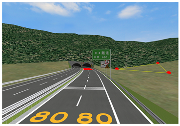
Figure 1. Driving simulator used in the study.
Sustainability 14 03377 g001
Figure 2. Horizontal section view of driving simulation scene on experimental section.
Sustainability 14 03377 g002
Figure 3. Vertical section view of driving simulation scene on experimental section.
Sustainability 14 03377 g003
Figure 4. Schematic diagram of tunnel entrance location.
Sustainability 14 03377 g004
Figure 5. Statistics of section speed per 100 m for the three combinations of static facilities.
Sustainability 14 03377 g005
Figure 6. Lateral offset distribution in different combinations of static facilities.
Sustainability 14 03377 g006
Figure 7. Area of the main visual field of the eye tracker.
Sustainability 14 03377 g007
Figure 8. Rank sum test results for area A.
Sustainability 14 03377 g008
Figure 9. Rank sum test results for area B.
Sustainability 14 03377 g009
Figure 10. Rank sum test results for area D.
Sustainability 14 03377 g010
Figure 11. Power spectrum of wavelets in each layer.
Sustainability 14 03377 g011
Figure 12. High-frequency energy values of steering wheel angle coefficients for different combinations of static facilities.
Sustainability 14 03377 g012
Table 1. Static facility combination setting scheme for bridge tunnel transition sections.
SceneSigns and Markings
Features
Driving Simulation Scene
ZH 1
  • Only facade markings and tunnels names.
  • Set white in the tunnel to realize the lane dividing line.
Sustainability 14 03377 i001
ZH 2
  • Add a tunnel name sign, a combination sign for speed limit and no overtaking at the tunnel entrance.
  • Thin red pavement is added at the entrance of the tunnel.
Sustainability 14 03377 i002
ZH 3
  • Add a tunnel name sign at the tunnel entrance, and a longitudinal combination sign prohibiting overtaking and speed limit.
  • Yellow speed limit markings and horizontal deceleration markings are set at the tunnel entrance.
Sustainability 14 03377 i003
Table 2. Test ranking of three combinations of static facilities.
Inspection ParametersRankSignificanceInspection ParametersRankSignificance
ZH 1
section 85-bit speed
2.7p < 0.05, significant differenceZH 1
standard deviation of section speed
2.7p < 0.05, significant difference
ZH 2
section 85-bit speed
1.0ZH 2
standard deviation of section speed
1.0
ZH 3
section 85-bit speed
2.3ZH 3
standard deviation of section speed
2.3
Table 3. Statistics of lane change behavior and driving distance in different combinations of static facilities.
SceneAverage Number of Lane Changes (m/Person)Average Driving Length on the Line (m/Person)
ZH 10.5030.63
ZH 20.0016.71
ZH 30.1435.00
Table 4. Statistics of lane change behavior in different combinations of static facilities.
Combination of Static FacilitiesAverage Distance from Lane Change Action Point to the Entrance(m)Average Distance from Lane Change Completion Point to the Entrance(m)Average Lane Change Distance(m)
ZH 1232.338181.58950.749
ZH 2269.297201.05768.240
ZH 3249.565193.01656.549
Table 5. Fixation time statistics for different combinations of static facilities.
ZH 1ZH 2ZH 3
1N/A3.081.44
21.520.880.8
40.721.6N/A
51.322.132.36
6N/A0.961.04
9N/A2.842.32
Fixation frequency50%100%83.30%
Average fixation time0.591.921.33
Publisher’s Note: MDPI stays neutral with regard to jurisdictional claims in published maps and institutional affiliations.

