
Control of Early-Age Cracking in Super-Long Mass Concrete Structures

Abstract
:1. Introduction
2. Project Background
2.1. Materials
2.2. Instrumentation
2.3. General Arrangement
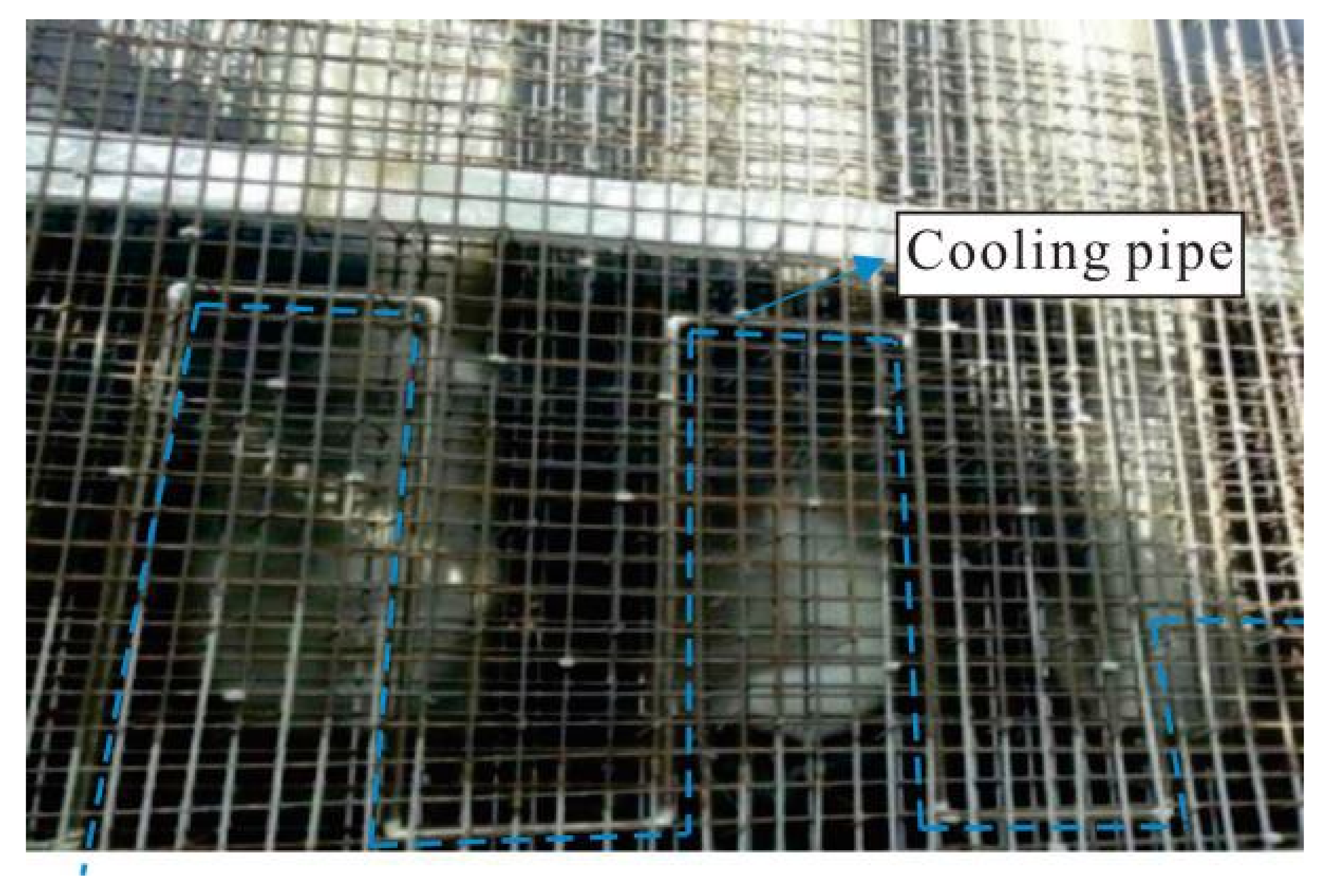
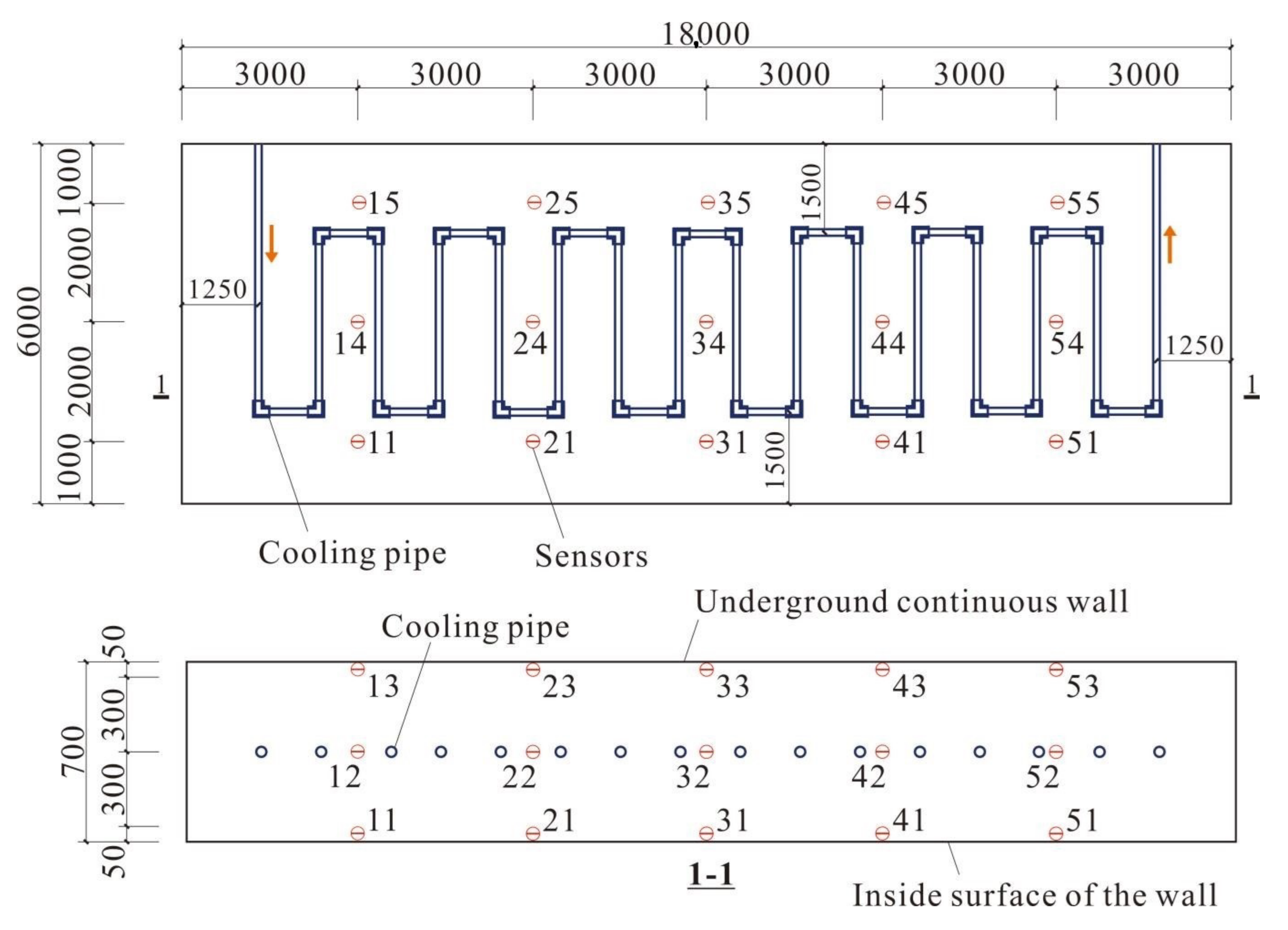
2.3.1. Pipe Cooling Method
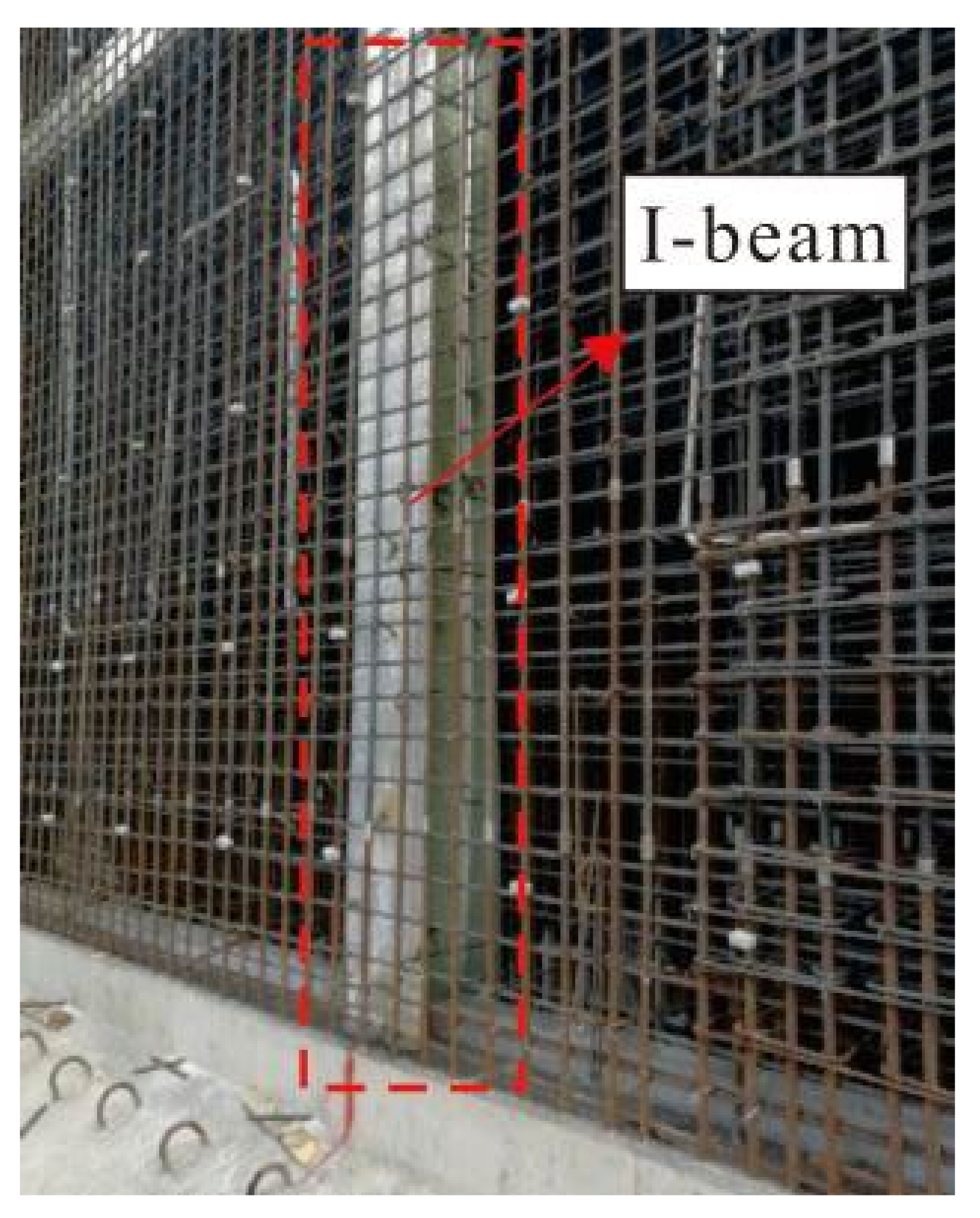
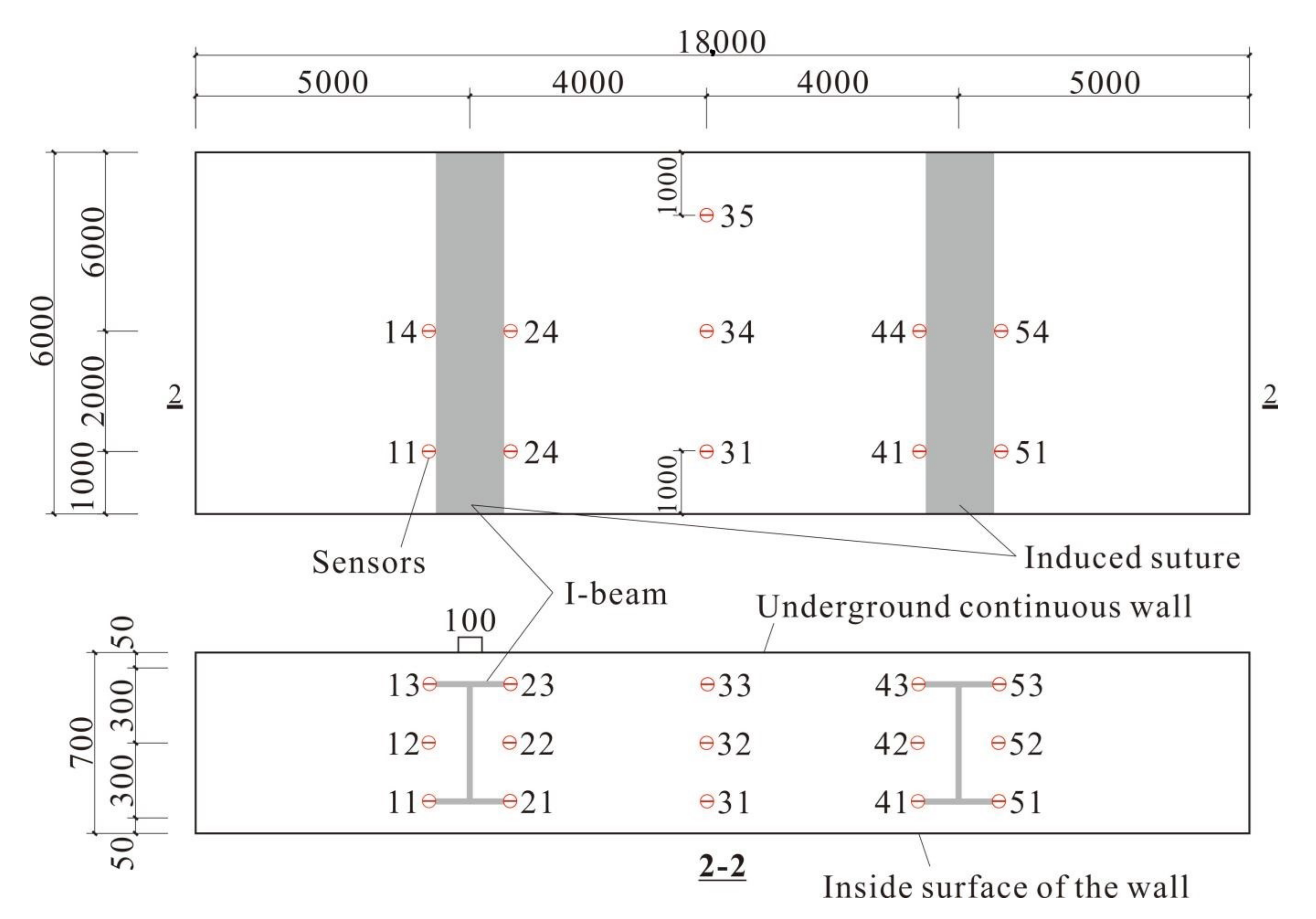
2.3.2. Induced Joint Method
2.3.3. Alternate Bay Method
- The construction length and construction interval time of the structure were calculated according to the site working conditions. The construction interval time was 7 days, and the construction length at one time was 18 m;
- The temperature of the concrete entering the formwork was controlled within 30 °C;
- A 15 mm thick piece of Styrofoam was attached between the primary lining and the other lining to allow volume expansion of the concrete;
- To eliminate defects from fast heat conduction in the steel formwork, the formwork was removed 3 days after the concrete was poured, maintenance was performed in time, and the maintenance system was adjusted according to the measured data.
2.3.4. Summary
3. Results and Discussion
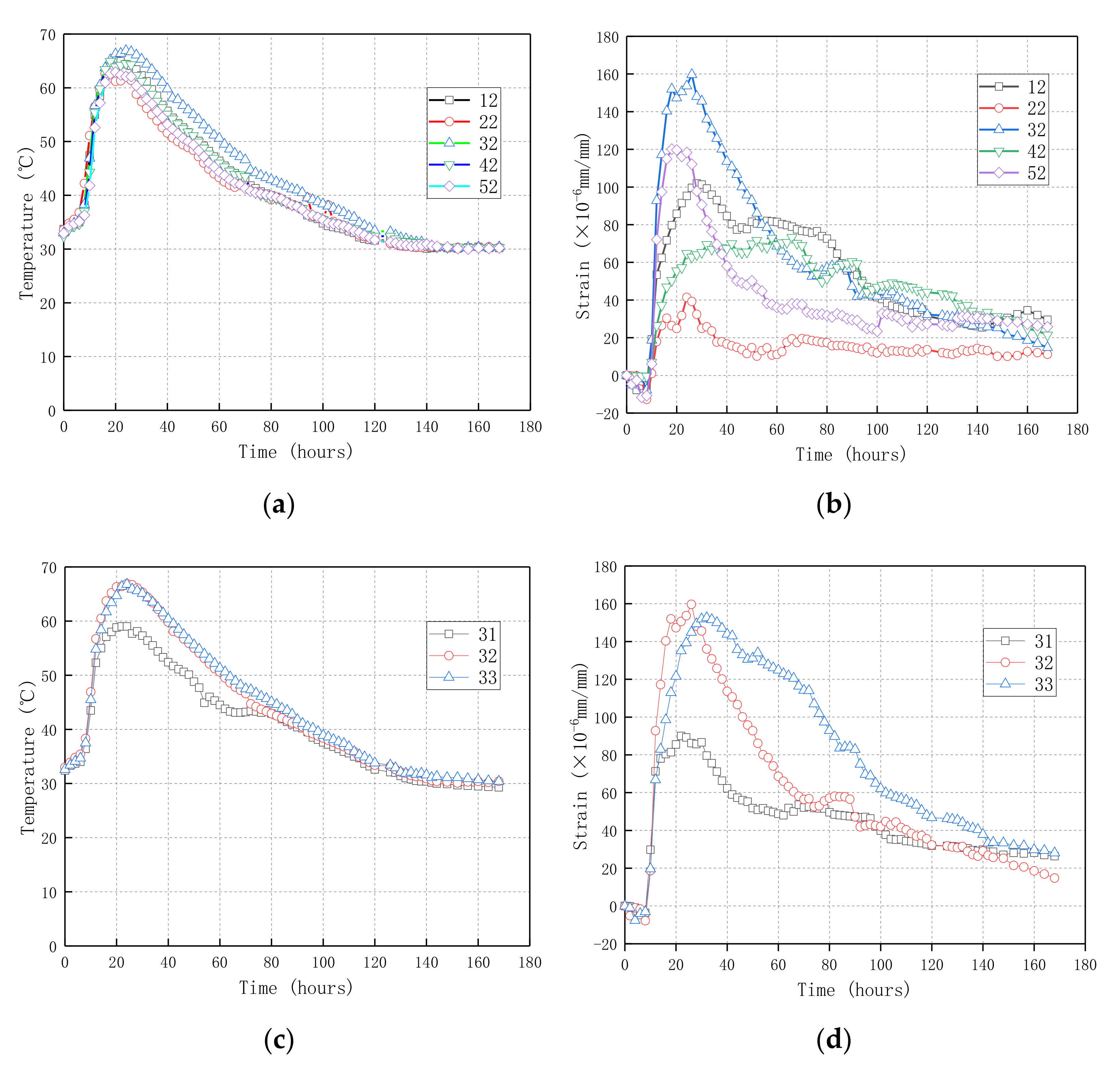
3.1. Pipe Cooling Method
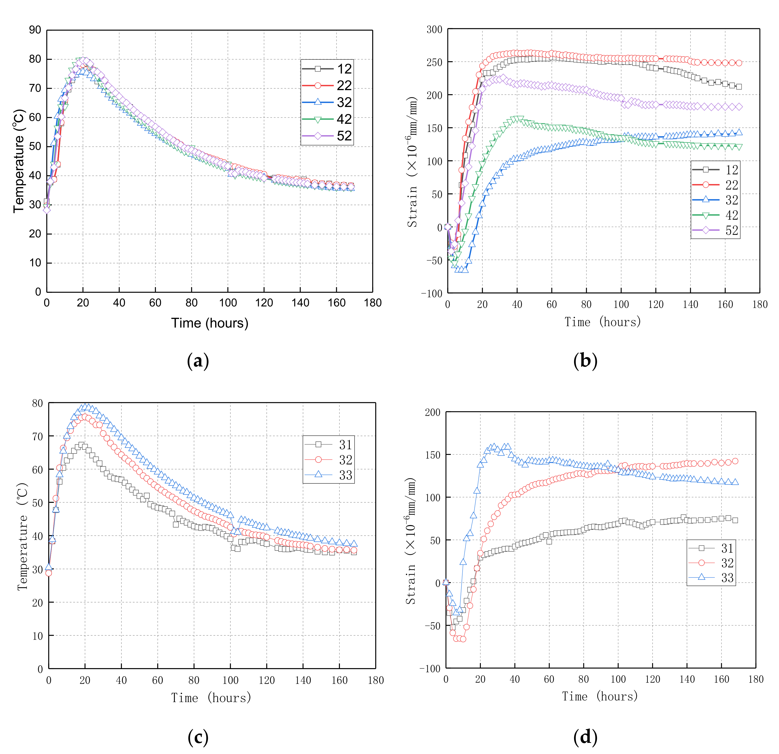
3.2. Induced Joint Method
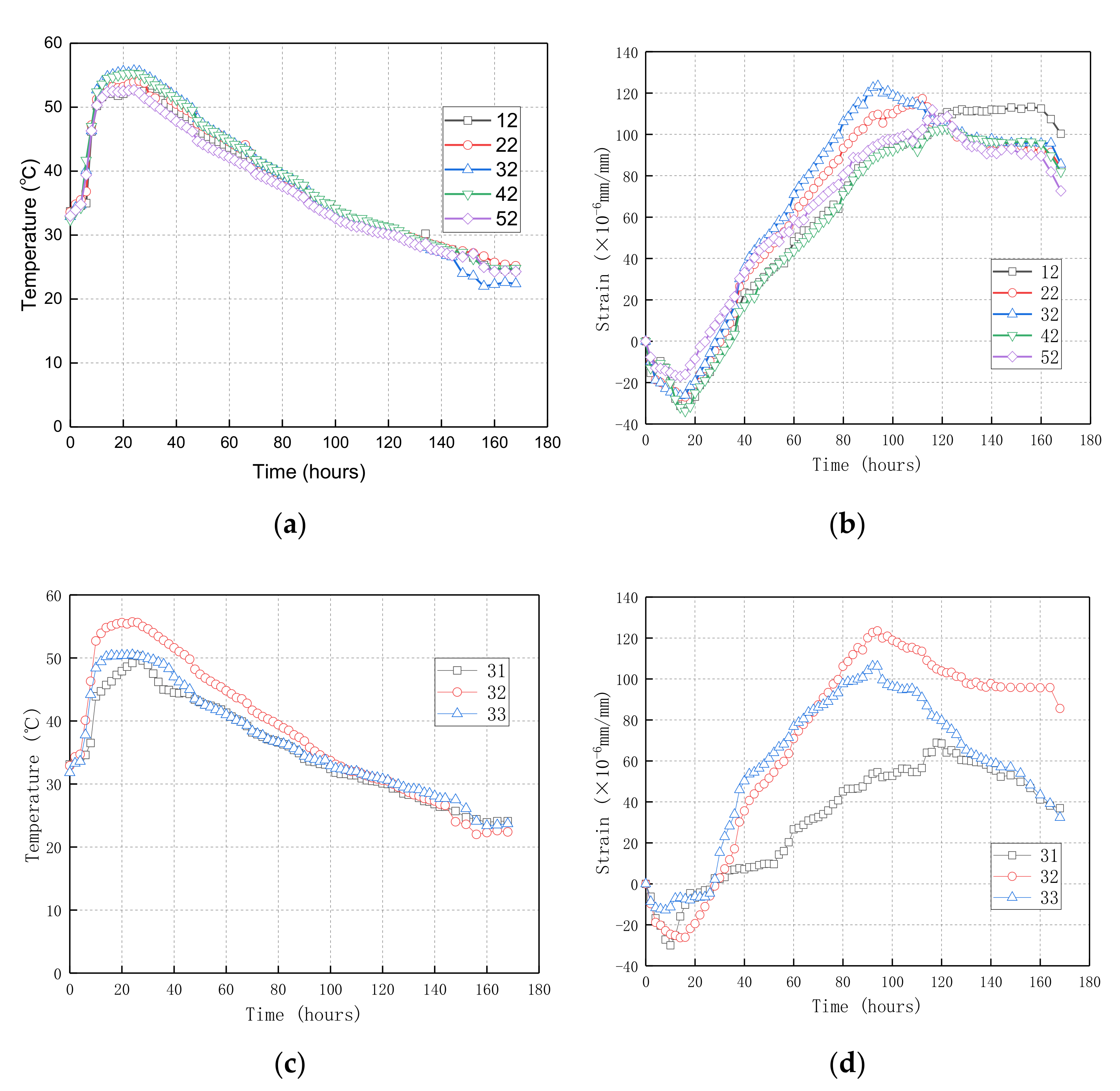
3.3. Alternate Bay Construction Method
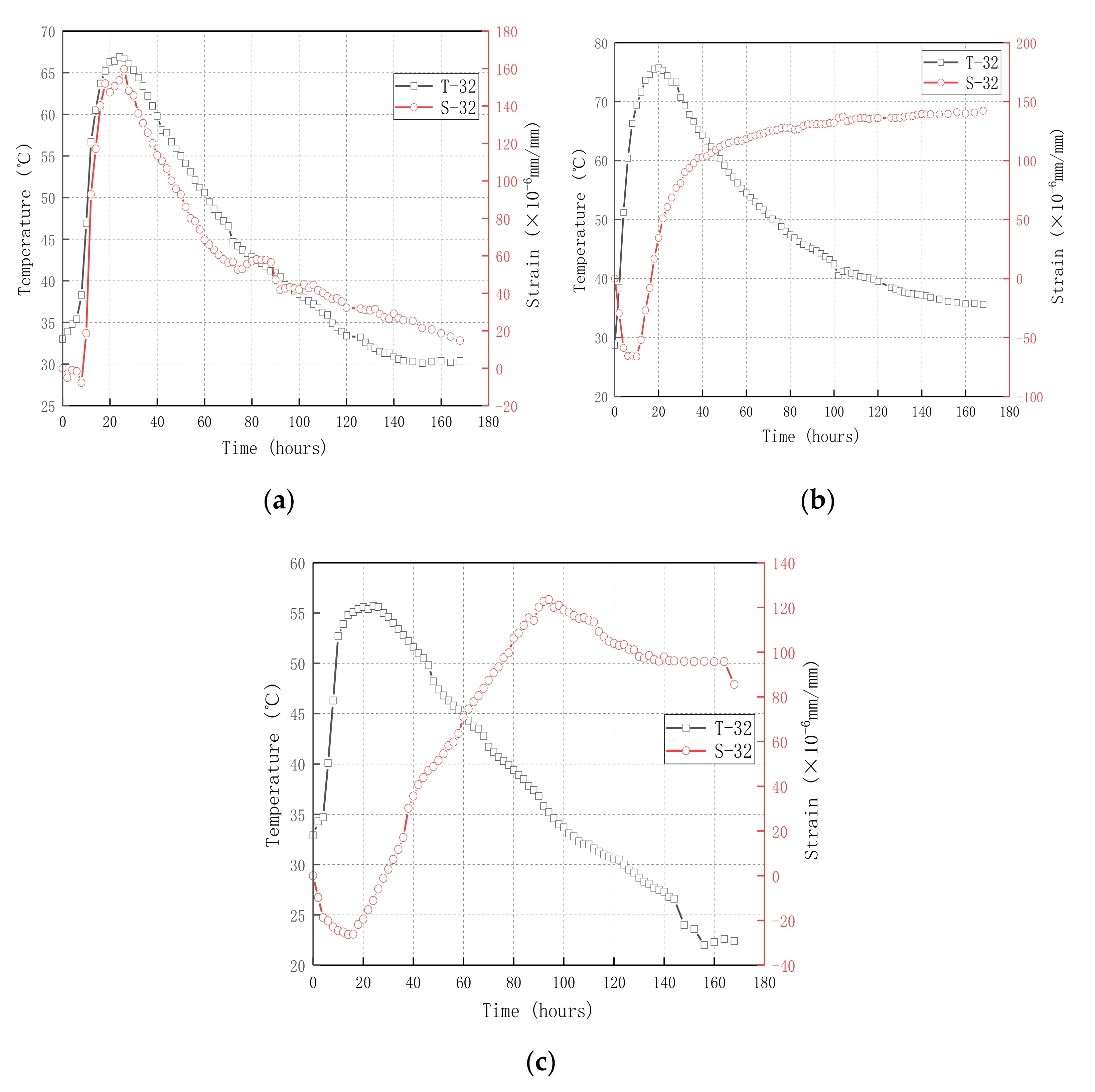
3.4. Relationship between Temperature and Strain
3.5. Analysis of Different Control Methods
4. Conclusions
- The vertical pipe cooling method with water cooling in the pouring period was applied, which reduced the heat of hydration in the concrete structure. The temperature of the sidewall structure reached its peak value in 24 h and reached the ambient temperature in 120 h. The pipe cooling method reduced the hydration heat by approximately 13 °C and effectively reduced the internal temperature strain of the structure. The time variation law of wall strain and the temperature was synchronous. The vertical pipe cooling method reduces the hydration heat of materials and is more suitable for early-age cracking structures that are only sensitive to temperature changes.
- An I-beam was inserted into the structure to create a sudden change in stiffness, and this induced joint method reduced the internal restraint strain of the structure. The maximum temperature and strain peak in the structure appeared in the web, the strain in the middle of the structure grew slowly, and the changes in strain over time lagged behind the changes in temperature. The induced joint method releases the restraint strain and is more suitable for early-age cracking structures that are only sensitive to constraints.
- The alternate bay construction method is a comprehensive measure to control the early-age cracking of concrete structures. By reasonably setting the construction length and the construction interval time, the alternate bay construction method reduces structural constraints, optimises the maintenance system, delays the development process of structural temperature and strain, and reduces the internal tensile strain of the structure. The peak values of the temperature and strain of the structure appeared in the middle of the wall, and the change in strain over time lagged behind the change in temperature. The alternate bay construction method, which comprehensively considers the influence of both temperature and restraint, is the most effective measure.
Author Contributions
Funding
Informed Consent Statement
Data Availability Statement
Acknowledgments
Conflicts of Interest
References
- Meyer, M.D.; Watson, L.S.; Walton, C.M.; Skinner, R.E. Control of cracking in concrete state of the art. In Basic Research and Emerging Technologies Related to Concrete Committee; Transportation Research Board: Washington, DC, USA, 2006; pp. 1–41. [Google Scholar]
- Bofang, Z. Thermal Stresses and Temperature Control of Mass Concrete; Butterworth-Heinemann: Oxford, UK, 2013. [Google Scholar]
- ACI Committee. 231R-10 Report on Early-Age Cracking: Causes, Measurement, and Mitigation. In ACI 231R-10; Han-sen, W., Ed.; American Concrete Institute (ACI): Farmington Hills, MI, USA, 2010; pp. 1101–1116. [Google Scholar]
- Rilem, T.C. Avoidance of thermal cracking in concrete at early ages. Mater. Struct. 1997, 30, 451–464. [Google Scholar]
- ACl Committee 207. Effect of Restraint, Volume Change, and Reinforcement on Cracking of Mass Concrete. ACl Mater. J. 1990, 87, 271–295. [Google Scholar]
- Bentur, A. Early Age Cracking in Cementitious Systems. In Report of RILEM Technical Committee 181-EAS: Early Age Shrinkage Induced Stresses and Cracking in Cementitious Systems; RILEM Publications SARL: London, UK, 2003. [Google Scholar]
- Shaikh, F.U.A. Effect of cracking on corrosion of steel in concrete. Int. J. Concr. Struct. Mater. 2018, 12, 3. [Google Scholar] [CrossRef] [Green Version]
- Kanavaris, F. Early Age Behaviour and Cracking Risk of Concretes Containing GGBS; Queen’s University Belfast: Belfast, UK, 2017. [Google Scholar]
- Knoppik-Wrobel, A. Analysis of Early-Age Thermal-Shrinkage Stresses in Reinforced Concrete Walls; Silesian University of Technology: Gliwice, Poland, 2015. [Google Scholar]
- Di Luzio, G.; Cusatis, G. Solidification–microprestress–microplane (SMM) theory for concrete at early age: Theory, validation and application. Int. J. Solids Struct. 2013, 50, 957–975. [Google Scholar] [CrossRef] [Green Version]
- Goto, T.; Sato, T.; Sakai, K. Cement Shrinkage Reducing Agent and Cement Composition. U.S. Patent #4547223, 15 November 1985. [Google Scholar]
- Weiss, J.; Lura, P.; Rajabipour, F.; Sant, G. Performance of shrinkage-reducing admixtures at different humidities and at early ages. ACI Mater. J. 2008, 105, 478–486. [Google Scholar] [CrossRef]
- Liu, F.; Shen, S.-L.; Hou, D.-W.; Arulrajah, A.; Horpibulsuk, S. Enhancing behavior of large volume underground concrete structure using expansive agents. Constr. Build. Mater. 2016, 114, 49–55. [Google Scholar] [CrossRef]
- Japan Concrete Institute. Report of JCI committee on autogenous shrinkage of concrete. In Proceedings of the International Workshop on Autogenous Shrinkage of Concrete, Hiroshima, Japan, 13–14 June 1998; pp. 5–28. [Google Scholar]
- Tankasala, A.; Schindler, A.K. Early-Age Cracking of Lightweight Mass Concrete. ACI Mater. J. 2020, 117, 223–232. [Google Scholar] [CrossRef]
- Klemczak, B.; Batog, M.; Pilch, M.; Żmij, A. Analysis of Cracking Risk in Early Age Mass Concrete with Different Aggregate Types. Procedia Eng. 2017, 193, 234–241. [Google Scholar] [CrossRef]
- Zuo, Z.; Hu, Y.; Li, Q.; Zhang, L. Data Mining of the Thermal Performance of Cool-Pipes in Massive Concrete via In Situ Monitoring. Math. Probl. Eng. 2014, 2014, 985659. [Google Scholar] [CrossRef]
- Kim, K.-H.; Jeon, S.-E.; Kim, J.-K.; Yang, S. An experimental study on thermal conductivity of concrete. Cem. Concr. Res. 2003, 33, 363–371. [Google Scholar] [CrossRef]
- Zhang, X.; Zhang, X.; Yan, T.; Huang, Y.; Liu, Q.; Wang, X. Experimental analysis and numerical calculation on equivalent strength of induced joints of different ages and weakening degrees. J. Ceram. Soc. Jpn. 2019, 127, 642–650. [Google Scholar] [CrossRef] [Green Version]
- Wang, T.M. Control of Cracking in Engineering Structure, 2nd ed.; China Construction Industry Press: Beijing, China, 2017; pp. 616–626. ISBN 978-7-112-20690-2. [Google Scholar]
- Binru, J.; Yan, W.; Liming, C.; Changsheng, G. Temperature stress calculation and crack control of long concrete walls. China Civ. Eng. J. 2011, 44, 36–41. [Google Scholar]
- Kanavaris, F.; Azenha, M.; Soutsos, M.; Kovler, K. Assessment of behaviour and cracking susceptibility of cementitious systems under restrained conditions through ring tests: A critical review. Cem. Concr. Compos. 2019, 95, 137–153. [Google Scholar] [CrossRef] [Green Version]
- Wyrzykowski, M.; Hu, Z.; Ghourchian, S.; Scrivener, K.; Lura, P. Corrugated tube protocol for autogenous shrinkage measurements: Review and statistical assessment. Mater. Struct. 2017, 50, 57. [Google Scholar] [CrossRef]
- Kanavaris, F.; Azenha, M.; Schlicke, D.; Kovler, K. Longitudinal restraining devices for the evaluation of structural behaviour of cement-based materials: The past, present and prospective trends. Strain 2020, 56, 12343. [Google Scholar] [CrossRef]
- Altoubat, S.A.; Lange, D.A. Creep, Shrinkage, and Cracking of Restrained Concrete at Early Age. ACI Mater. J. 2001, 98, 323–331. [Google Scholar] [CrossRef]
- Kovler, K. Testing system for determining the mechanical behaviour of early age concrete under restrained and free uniaxial shrinkage. Mater. Struct. 1994, 27, 324–330. [Google Scholar] [CrossRef]
- Zhu, H.; Li, Q.; Hu, Y.; Ma, R. Double Feedback Control Method for Determining Early-Age Restrained Creep of Concrete Using a Temperature Stress Testing Machine. Materials 2018, 11, 1079. [Google Scholar] [CrossRef] [Green Version]
- Breitenbücher, R. Investigation of thermal cracking with the cracking-frame. Mater. Struct. 1990, 23, 172–177. [Google Scholar] [CrossRef]
- Samouh, H.; Rozière, E.; Loukili, A. The differential drying shrinkage effect on the concrete surface damage: Experimental and numerical study. Cem. Concr. Res. 2017, 102, 212–224. [Google Scholar] [CrossRef]
- Wang, X.; Huang, Y.; Wu, G.; Fang, C.; Li, D.; Han, N.; Xing, F. Effect of nano-SiO2 on strength, shrinkage and cracking sensitivity of lightweight aggregate concrete. Constr. Build. Mater. 2018, 175, 115–125. [Google Scholar] [CrossRef]
- Chen, B.; Cai, Y.B.; Ding, J.T.; Jian, Y. Crack Resistance Evaluating of HSC Based on Thermal Stress Testing. Adv. Mater. Res. 2011, 168–170, 716–720. [Google Scholar] [CrossRef]
- Kovler, K.; Bentur, A. Cracking Sensitivity of Normal- and High-Strength Concretes. ACI Mater. J. 2009, 106, 537–542. [Google Scholar] [CrossRef]
- Lenormand, T.; Rozière, E.; Loukili, A.; Staquet, S. Incorporation of treated municipal solid waste incineration electrostatic precipitator fly ash as partial replacement of Portland cement: Effect on early age behaviour and mechanical properties. Constr. Build. Mater. 2015, 96, 256–269. [Google Scholar] [CrossRef]
- Tasri, A.; Susilawati, A. Effect of cooling water temperature and space between cooling pipes of post-cooling system on temperature and thermal stress in mass concrete. J. Build. Eng. 2019, 24, 100731. [Google Scholar] [CrossRef]
- Singh, P.R.; Rai, D.C. Effect of Piped Water Cooling on Thermal Stress in Mass Concrete at Early Ages. J. Eng. Mech. 2018, 144, 04017183. [Google Scholar] [CrossRef]
- Seo, T.S.; Kim, S.S.; Lim, C.K. Experimental Study on Hydration Heat Control of Mass Concrete by Vertical Pipe Cooling Method. J. Asian Arch. Build. Eng. 2015, 14, 657–662. [Google Scholar] [CrossRef]


| Material | CaO | SiO2 | Al2O3 | Fe2O3 | MgO | SO3 |
|---|---|---|---|---|---|---|
| Cement | 52.27 | 25.54 | 8.13 | 5.59 | 1.85 | 2.27 |
| Fly ash | 2.98 | 78.61 | 15.14 | 3.80 | 0.56 | 0.55 |
| Fineness of the 80 μm Screen Margin (%) | Specific Surface Area (m2/kg) | Standard Consistency (%) | Loss on Ignition (%) | Time of Initial Setting (min) | Time of Final Setting (min) | Compressive Strength (MPa) | |
|---|---|---|---|---|---|---|---|
| 3 d | 28 d | ||||||
| 1.726 | 345 | 25 | 1.75 | 161 | 218 | 27.4 | 50.4 |
| Code Grade | Concrete Composition (kg/m3) | Compressive Strength (MPa) | ||||||||
|---|---|---|---|---|---|---|---|---|---|---|
| Water | Cement | Fly Ash | Ground Slag | Sand | Gravel | Water Reducer | 3 d | 28 d | 56 d | |
| C45 | 151.2 | 294 | 94.5 | 31.5 | 713.2 | 1115.5 | 5.7% | 47.2 | 60.0 | 63.7 |
| Approaches | Measures |
|---|---|
| Pipe cooling method | A vertical cooling pipe is used to remove the heat from the interior of the mass concrete through cooling pipes of circulating water embedded in the concrete. |
| Induced joint method | I-beam is inserted into the structure to create a sudden change in stiffness, which causes cracks around the web of the I-beam to release stresses. |
| Alternate bay method | This systematic method includes a series of procedures, such as concrete mix proportion design, a reduction in the boundary constraints, setting of the construction length, and development of a maintenance system. |
Publisher’s Note: MDPI stays neutral with regard to jurisdictional claims in published maps and institutional affiliations. |
© 2022 by the authors. Licensee MDPI, Basel, Switzerland. This article is an open access article distributed under the terms and conditions of the Creative Commons Attribution (CC BY) license (https://creativecommons.org/licenses/by/4.0/).
Share and Cite
Wang, C.; Chen, Y.; Zhou, M.; Chen, F. Control of Early-Age Cracking in Super-Long Mass Concrete Structures. Sustainability 2022, 14, 3809. https://doi.org/10.3390/su14073809
Wang C, Chen Y, Zhou M, Chen F. Control of Early-Age Cracking in Super-Long Mass Concrete Structures. Sustainability. 2022; 14(7):3809. https://doi.org/10.3390/su14073809
Chicago/Turabian StyleWang, Chenfei, Yuehui Chen, Meili Zhou, and Fangjian Chen. 2022. "Control of Early-Age Cracking in Super-Long Mass Concrete Structures" Sustainability 14, no. 7: 3809. https://doi.org/10.3390/su14073809
APA StyleWang, C., Chen, Y., Zhou, M., & Chen, F. (2022). Control of Early-Age Cracking in Super-Long Mass Concrete Structures. Sustainability, 14(7), 3809. https://doi.org/10.3390/su14073809