Article

Applications of Hydrochar and Charcoal in the Iron and Steelmaking Industry—Part 2: Carburization of Liquid Iron by Addition of Iron–Carbon Briquettes

1
KTH Royal Institute of Technology, Material Science and Engineering, SE-100 44 Stockholm, Sweden
2
SWERIM AB, Process Metallurgy, SE-971 25 Luleå, Sweden
*
Author to whom correspondence should be addressed.
Sustainability 2022, 14(9), 5383; https://doi.org/10.3390/su14095383
Submission received: 31 March 2022 / Revised: 19 April 2022 / Accepted: 26 April 2022 / Published: 29 April 2022

Abstract

:
Hydrochar (a solid product from hydrothermal carbonization of organic feedstock) and charcoal have the potential to substitute coke and coal consumption in the iron and steelmaking processes for reduction of greenhouse gas (GHG) emissions. Among steelmaking processes, melt carburization is an important but less-studied application. In this study, briquettes produced with mixture a of iron powder, hydrochar or charcoal powder, and binder were tested as iron melt recarburizers. It was found that the hydrochar briquettes have good mechanical properties, whereas those of charcoal briquettes were poor. Melt carburization with briquettes was performed in a lab induction furnace (10 kg) in two steps: firstly, by heating up some briquettes with charged electrolytic iron from room temperature up to 1600 °C, followed by the addition of some briquettes into the melt. Recarburization efficiency (RE) during the first step of carburization was found to be controlled by the amount of carbon content bound in the solid phase (fixed carbon) determined at 1200 °C. Thus, the REs of charcoal briquettes (70–72%) were higher than those of hydrochar (43–58%) due to the higher fixed carbon contents in charcoal. REs obtained from the second step were strongly affected by the amount of briquette losses during their addition into the iron melt, which correlate with the mechanical strengths of the briquettes. Thus, the REs for hydrochar briquettes (48–54%) were higher than those of charcoal (26–39%). This study proves the feasibility of using hydrochar and charcoal as liquid steel recarburizers.

1. Introduction

Carbon serves an important role in iron and steelmaking processes. It is used as fuel, a reducing agent, a slag-foaming reagent, a carbon-alloying element of liquid steel, and also as a load-bearing component in the blast furnace (BF). However, except for the carbon that is dissolved in steel, most of the charged carbon is eventually released as CO and CO2 into the atmosphere as greenhouse gases (GHGs). This results in high CO2 emissions from the iron and steelmaking industry, representing 5–7% of the world’s total CO2 emissions [1]. The EU plans to become climate neutral by 2050, and to reach this goal, 80–95% of the CO2 emissions in 2050 need to be reduced compared to the 1990 level [1]. At the same time, the worldwide steel demand is on the rise [2], and the CO2 emission price for the EU Emission Trading System rose rapidly from 19.05 to 49.78 $USD/t GHG over the period of 2005–2021 [3]. Therefore, effective measures to reduce GHG emissions are necessary for the iron and steelmaking industry to thrive without large amounts of emission-related penalties incurred.
Research regarding substitution of fossil carbon with renewable biomass products in the BF and electric arc furnace (EAF) has been under rapid development in recent years [4,5,6,7]. In BF, biomass-derived carbon materials have been applied in cokemaking blends [8,9,10], in the production of bio-coke to replace lump coke [11,12], as a replacement for pulverized coal injection [13,14], as a solid fuel for iron ore sintering [15,16,17], and as a carbon composite agglomerate [18,19,20,21]. Biomass application in EAF steelmaking and direct-reduced iron/EAF (DRI-EAF) processes are of great future interest given that these are low CO2 steelmaking routes that are likely to become more prominent in the future [22,23]. The majority of studies concerning EAF have focused on fossil carbon replacement with biomass-based products for slag foaming [24,25,26,27,28] and fuel [29,30] purposes. However, it should not be neglected that about 8 wt% (~1.4 kg/t of hot metal [31]) out of the total consumed carbon during EAF steelmaking (15 kg/t of hot metal [31]) is used for carburization of melt.
Commercial recarburizers are usually fossil-based materials, which include graphite, anthracite, metallurgical coke, pitch coke, calcined petroleum coke, and silicon carbide [32]. The recarburizers could be charged into the EAF in the scrap basket or added directly into the melt. The recarburization efficiency (RE) for commercialized recarburizers varies significantly in the range from 35 up to 100%, with an average of 60.8% reported by Somerville et al. [33] based on 18 industrial heats. This means that, on average, 39.2% of the added recarburizers were not dissolved in melt. Similar findings were reported by Robinson et al. [34], who found that there were great fluctuations in carbon content ranging from 0.058 to 0.249 wt% in the first melt sample taken after melt-down during annual production in a 50t EAF. Thus, with the existing practice of the addition of commercial recarburizers, a significant amount of recarburizers are lost to GHGs. Therefore, some CO2 emissions during EAF steelmaking could be mitigated by substituting fossil-based recarburizers with renewable biomass-based products.
RE is an important and useful factor to evaluate the performance of a recarburizer. RE is typically calculated as [35]
R E = W t C t W i C i   W n · C n · 100 %
where W i and W t are the weights of liquid steel before and after addition of recarburizers, respectively. W n is the weight of carbon-containing material. C n is the total carbon content in carbon-containing material. C i and C t are the carbon concentration in the melt before and after addition of recarburizers, respectively. A high RE reduces the amount of recarburizers required to reach the target carbon concentration in the melt and minimizes the GHG emissions. Due to the differences between fossil-based recarburizers and biomass-based products in terms of their chemical compositions and physical properties, their reported REs differ significantly in the literature. Therefore, it is important to evaluate REs of biomass-based materials with laboratory experiments for more accurate calculations of substitution rate for fossil-based recarburizers.
Somerville et al. [33] conducted laboratory melt carburization experiments of commercial recarburizers and different types of charcoals with different volatile matter contents. They found that RE was inversely proportional to volatile matter content in the carbon materials. They proposed that the volatile matter, including tar and gases such as CO, CO2, H2, and CH4 from devolatilization of charcoal, were lost to off-gas and were not dissolved efficiently in the melt. They also compared the performance of commercial recarburizers and charcoal in industrial trials by adding the carbon materials during tapping from EAF and in a ladle furnace. The average value of RE was 67.8% for a commercial recarburizer and 86.4% for charcoal. Laboratory melt carburization experiments conducted under the GREENEAF2 project [24] reported RE of 91% for anthracite, 80% for gasification residues, 75–80% for pyrolyzed wood, 45–50% for torrefied biomasses, and 40% for virgin palm kernel shells and hydrochar. Robinson et al. [34] conducted laboratory dissolution experiments by charging briquettes with a mixture of 80 wt% iron powder and 16 wt% of carbonaceous materials into liquid steel. They reported the graphite briquettes yielded an RE of 97%, anthracite briquettes yielded an RE of 61%, and biochar briquettes yielded an RE of 47–58%. The authors also conducted six industrial trials by substituting one-third of anthracite recarburizers added in the first scrap basket with charcoal and charged them into a 50t EAF. The authors reported no deviation from usual production in terms of carbon and sulfur concentrations in the melt. The current knowledge is that charcoal yields high, consistent RE in laboratory carburization experiments, second only to graphite and anthracite. Charcoal has also shown better performance than some commercial recarburizers during industrial trials.
However, the main challenge of charcoal is its high porosity, which results in its low bulk density. Non-densified charcoal incurs high transportation costs [36], significant mass losses during transportation and handling [36], high risk of contamination by soil and sand [37], and it generates large amount of dust when charged into furnaces. Solutions to this include densifying the biomass before pyrolysis [38] or densifying the charcoal by means of addition of a binder [39,40]. In cases where high briquette strength is required, a second heat treatment at high temperatures (500–1100 °C) after the densification step could be applied [36], which is typical for production of bio-coke [11]. Densification can take place at room temperature (cold briquetting) or under heated conditions. Cold briquetting is preferred as it is more convenient and requires less energy. However, it has been reported that large amounts of water or water-based solutions (>15 wt%) need to be added to charcoal for successful briquetting at room temperature [39,40,41]. Water is not a suitable binder if the briquettes are intended to be directly charged into molten steel as it can lead to explosion [42]. Therefore, a water-free and carbon-rich binder is preferred for briquettes produced for carburization purpose. Pyrolysis oil has been used as a binder for producing biocarbon briquettes and compressive strength of the briquette up to 0.44 MPa has been reported [11,43]. Meanwhile, hydrothermal carbonization is a promising technology to convert biomass into hydrochar with strong bonding capabilities [43,44,45,46,47,48,49]. The compressive strength of binderless hydrochar pellets was reported to be as high as 9.4 MPa [50]. Hydrochar has also been used as a solid binder to strengthen wood pellets [47] and torrefied biomass pellets [47,48]. Additionally, hydrochar itself is a carbon-rich material that could be used as a recarburizer. It should be addressed that even after densification, charcoal briquettes were reported to have limited penetration in slag due to their low densities [25]. This can prevent effective contact of briquettes with the molten steel, resulting in a low RE. By briquetting biomaterials with iron powder and a binder, the mechanical strength and apparent density of the briquette could be enhanced simultaneously. Considering the field of carbon dissolution study, there is a lack of investigation regarding the impact of the addition method of recarburizers on RE. The addition method, under some circumstances, could be more important than the compositions of the recarburizer.
The aim of this study was to, firstly, investigate the feasibilities of briquetting hydrochar and charcoal powder with iron powder, with or without the addition of a binder, and characterize the mechanical strength and structures of the briquettes; secondly, compare the RE of hydrochar and charcoal briquettes obtained from two different addition methods; and thirdly, compare the REs of hydrochar and charcoal briquettes obtained in the present study with other biomass-based materials and fossil-based recarburizers in the literature.

2. Materials and Methods

2.1. Characterization of Carbonaceous Materials

2.1.1. Description of Materials

The three biomass-based carbon materials examined in this study were Charcoal 1, Charcoal 2, and Lemon Hydrochar. The production processes, proximate, and ultimate analysis of the three carbon materials have been described in the other part of this work [51]. The carbon materials were ground into a fine powder and subsequently sieved to <63 μm for production of iron–carbon briquettes (ICBs). Particle size distribution (PSD) of the iron powder, carbon powder, and binder were analyzed with Camsizer (Microtrac Camsizer X2) with 20 g of materials each. Densities of sieved powder of Charcoal 1, Charcoal 2, and Lemon Hydrochar were measured with a liquid pycnometer using water as medium. The averaged density was obtained from 5 density measurements. The binder used for enhancing bonding in ICBs was from PALMERHOLLAND (Orgasol® 3502 D NAT 1). The ultimate analysis of the three carbon materials and the binder is shown in Table 1. Chemical composition analysis of iron powder (IP) for producing ICBs and the electrolytic iron (EI) used during carburization experiments are shown in Table 2.

2.1.2. Characterization of Binder

In order to investigate the devolatilization behavior of the binder, thermogravimetric analysis (TGA) of the 10 mg binder was performed. The experimental procedure has been elaborated in the other part of our work [51].

2.2. Briquetting and Characterization of Iron–Carbon Briquettes

A sum of 100 g of iron powder (IP), char powder, and binder was thoroughly mixed and filled in a steel mold. The aim of adding iron powder was to increase the apparent density of the briquettes, such that they could penetrate the melt deeper when they are directly added into the melt. Briquetting was performed at room temperature with a hydraulic piston press at 155 MPa. Maximum pressure was maintained for 30 s before ejection of briquettes from the mold. Cylindrical briquettes of Ø40 mm and ca. 24 mm height were obtained. The obtained ICBs and their corresponding compositions are shown in Table 3.
A cross-section cold compression test (CCS) was conducted to evaluate the briquette’s mechanical strength. The compression device automatically recorded the peak pressure after cracking was observed in the briquette. Drop tests were performed to evaluate durability of briquettes during transportation, loading, and unloading processes. Each briquette was dropped with the flat face facing down from a 1.0 m height onto a steel plate. Given that small briquette pieces and fine powder cannot be utilized effectively during the addition process, the minimum possible weight loss of briquettes was evaluated by weighing the biggest briquette piece after each drop. The drop test was repeated until the retained part of the briquette was less than 1% of its initial weight or had survived 15 drops. It was assumed that the briquette had to survive 7 drops to be deemed as acceptable for transportation and handling [52].
The apparent densities of the briquettes were measured using a setup shown in Figure 1. Firstly, the weight of each briquette was measured with a weight balance. Secondly, the volume of the briquette was determined by fully submerging a briquette in a beaker containing water. The briquette had been placed in an iron wire basket that was attached to a lab stand to avoid the briquette sinking to the bottom of the beaker. The volume of the briquette was calculated by dividing the weight difference before and after submerging the briquette in water by the density of water at 25 °C. The briquette had been wrapped in a thin layer of plastic film prior to immersion in water to prevent penetration of water into the briquettes’ pores. The volume of the basket and plastic film was assumed negligible. The volume of each briquette was measured 5 times to obtain an average value. The apparent density of the briquette was then calculated by dividing the weight of the briquette by its averaged volume.
A scanning electron microscope (SEM) (Hitachi S-3700N) equipped with Bruker AXS XFlash Detector 4010 (Billerica, MA, USA) was used to study the fractured surfaces of ICBs. A small piece (~1 g) was cracked off from the ICB and dried in an oven at 105 °C for 2 h prior to analysis. Each briquette piece was fixed on a steel sample holder using copper tape and sputtered with Au/Pd. Acceleration voltage of 15 kV and working distance of 8–11 mm was used for taking images.

2.3. Melt Carburization with Iron–Carbon Briquettes

Evaluation of carburization efficiency of ICBs was carried out in a 10 kg capacity induction furnace and its schematic is shown in Figure 2a. A total of 8 ICBs of the same mixture of materials used for the carburization experiment were weighted before each experiment. During Step 1, 4 ICBs were carefully placed in an alumina crucible, and 2 kg of EI was placed on top of it. The alumina crucible was placed in a graphite susceptor for induction heating. All experimental equipment, such as alumina crucible, thermocouple, and the 4 liquid steel samplers were placed inside a furnace chamber and the chamber was kept closed throughout the entire experiment to avoid oxidation of carbon materials. Before each experiment, the furnace chamber was vacuumed and refilled with nitrogen gas three times to remove oxygen inside the chamber. During experiment, a constant nitrogen flow was introduced into the furnace chamber to maintain an over-pressure of 3–15 mbar to avoid air ingress. Heating was performed at a rate of approximately 50 K/min, such that the materials in the crucible were melted in under 30 min. This was to simulate meltdown time of the first scrap basket (20 t) in industrial EAF (60 t capacity) of 20 min [53]. After 30 min, more EI was gradually introduced into the crucible at a constant mass feeding rate with a vibrating feeder until a total of 10 kg was added. The EI was added gradually instead of in a big batch to prevent skull formation that could disturb the melting process. Then, another 30 min was allowed for melting down of EI and homogenization of the melt, such that a total of 60 min was used, similarly to the tap-to-tap time of a typical EAF of 65–75 min [54]. After confirming that the melt temperature was 1600 ± 10 °C by inserting a thermocouple into the melt, the steel sample S0 was taken with a liquid sampler to check the initial carbon and sulfur concentrations of the melt. Step 2 of carburization was subsequently conducted by adding 4 ICBs with the same briquette recipe as Step 1 into the melt. The heating powder was increased momentarily to compensate for the temperature drop of the melt. The melt temperature was kept in the range of 1600 ± 20 °C during the subsequent period. Then, 3 melt samples were taken every 30 s (S1,S2,S3) to determine the increase of carbon and sulfur concentrations in the melt. Three consecutive melt samples were taken to ensure a stable carbon concentration had been obtained in the melt for accurate evaluation of RE. The experimental procedure is summarized in Figure 2b. The carbon and sulfur concentrations of all liquid steel samples (S0–S3) were measured by a LECO analyzer (LECO CS844).

3. Results

3.1. Thermogravimetric Analysis of Binder

The thermogravimetric analysis of the binder is shown in Figure 3. Data were plotted between 120 °C and 960 °C, given that there was no decomposition but only drying of materials below 120 °C. It could be seen that the binder had a very low thermal stability and decomposed in a narrow temperature range from 370 °C to 540 °C with a mass loss peak at 478 °C. The binder showed 92.8% weight loss when heated up to 540 °C, and its weight stabilized above this temperature. The maximum rate of mass loss of the binder was much higher than the Lemon Hydrochar and the two charcoals, meaning that it was significantly more reactive. The mass loss rate was in the order of binder (−2.2 wt%/K), followed by Lemon Hydrochar (−0.5 wt%/K [51]), Charcoal 1 (−0.06 wt%/K [51]), and Charcoal 2 (−0.03 wt%/K [51]).

3.2. Characterization of Briquettes

The densities of different powders used for making ICBs and their PSDs are shown in Table 4. Densities of the IP and binder were taken from references. The terms d10, d50, and d90 denote the maximum particle size, below which 10%, 50%, and 90% of particles were found, respectively. IP had the coarsest median particle size, 80.84 µm, followed by Lemon Hydrochar (29.88 µm), Charcoal 1 (18.66 µm), binder (11.39 µm), and Charcoal 2 (10.04 µm). The apparent densities of briquettes are shown in Table 5 and the measurement error was below 3%. The densities of molten EAF slags during stainless steelmaking were reported to be between 3150–3410 kg/m3 in a temperature range of 1640–1754 °C [55]. Therefore, hydrochar briquettes might be able to penetrate liquid slag and reach the melt when it is added directly into the melt, while the charcoal briquettes could float on top the slag. The densities of the briquettes should be further increased in future work.
During CCS tests, the two hydrochar briquettes had strengths that exceeded the detectable limit of the hydraulic piston, 16 MPa. However, the two charcoal briquettes cracked immediately after stresses were applied, and no readings could be obtained from the pressure gauge. This difference is in agreement with the literature, where the strengths of the cold-briquetted hydrochar pellets were much higher than cold-briquetted charcoal pellets. For example, compressive strengths of hydrochar pellets made from cotton stalk hydrochar that were pelletized at 80 kN without binder addition were in the range of 2.9–9.4 MPa [50]. On the contrary, rice husk biochar pelletized with 30 kN showed lower compressive strength of 0.65 MPa [39], and a maximum compressive strength of 23 MPa was obtained when 15 wt% of sodium hydroxide solution was added as binder. Hu et al. [40] conducted cold briquetting of charcoal pyrolyzed at 550 °C and 650 °C. They reported at least 15 wt% water needed to be added as a binder to successfully eject the briquette from the mold without destruction. Maximum briquette strength of 4.78 MPa was obtained at a pelletizing pressure of 128 MPa and with the addition of 35 wt% water as binder. A similar finding was reported by Bazargan et al. [56] that without the addition of water, palm kernel shell biochar could not be ejected from briquetting mold.
The results from drop test of briquettes are plotted in Figure 4 and these could be used in conjunction with CCS to identify the difference between briquettes. It could be seen that the durability differed drastically between hydrochar briquettes and charcoal briquettes. Both hydrochar briquettes showed no signs of cracking until the seventh drop. The impact resistance of BR-LH16 appeared to be even better than BR-LH20, retaining 50.7% of its initial weight after 15 drops compared to 19.6% of BR-LH20. On the other hand, BR-C1 had only 20.6% of initial weight remaining after 2 drops, 3.5% of initial weight after 7 drops, and was totally destroyed on the eleventh drop. BR-C2 retained only 31% of initial weight after one drop, and was totally destroyed on the second drop. Both hydrochar briquettes were acceptable for transportation and handling since they survived at least seven drops, whereas the impact resistance of the two charcoal briquettes clearly needs to be improved. However, drop tests were only performed for one briquette per briquette recipe and more drop tests are required to get statistically representative results.
Table 4. Particle size distribution and densities of different powders used for making iron–carbon briquettes.
Iron PowderCharcoal 1Charcoal 2Lemon HydrocharBinder
Particle size distribution (µm)
d10 65.745.343.589.258.97
d50 80.8418.6610.0429.8811.39
d90 150.8946.2631.0954.4215.52
Density (kg/m3)7.874 [57]1.07 ± 0.080.76 ± 0.061.23 ± 0.021.085 ± 0.02 [58]
Table 5. Apparent densities of iron–carbon briquettes.
BR-LH20BR-LH16BR-C1BR-C2
Density (kg/m3)3.373.232.702.73
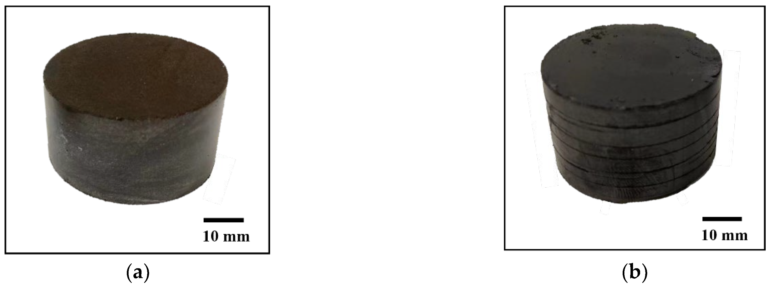
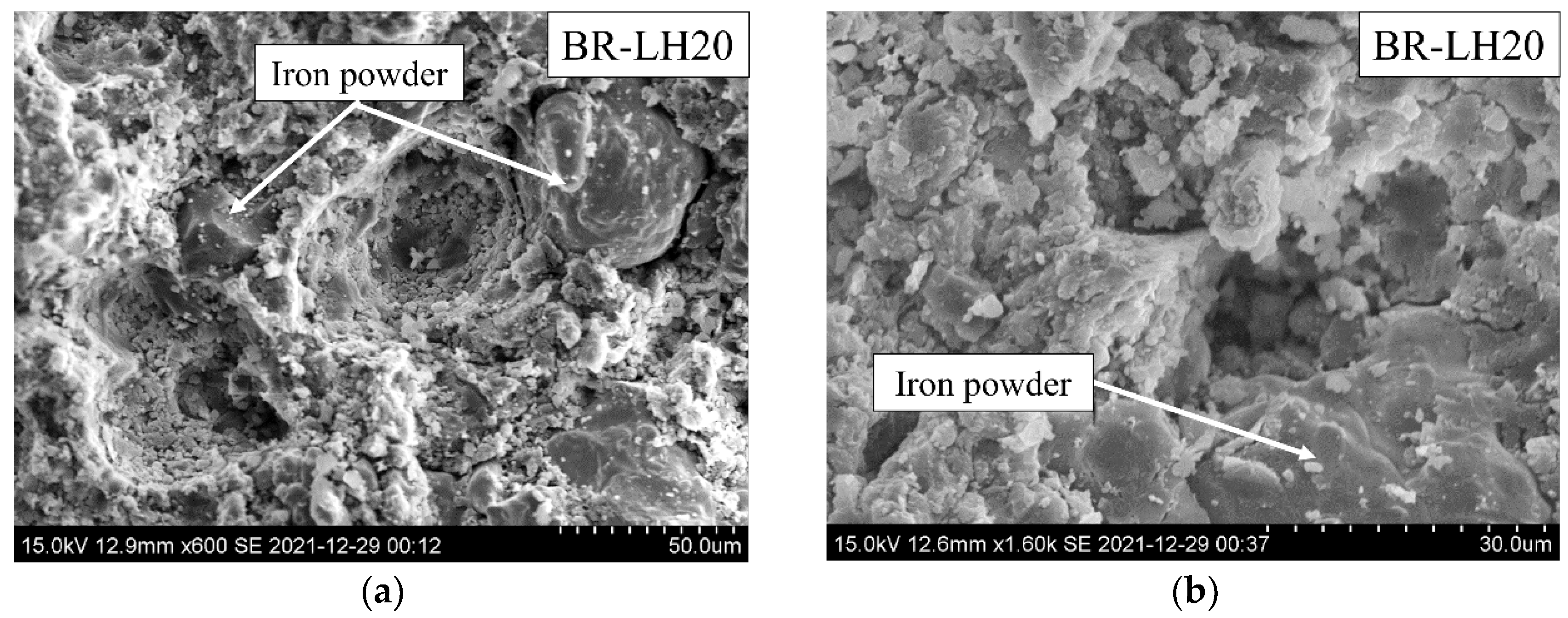
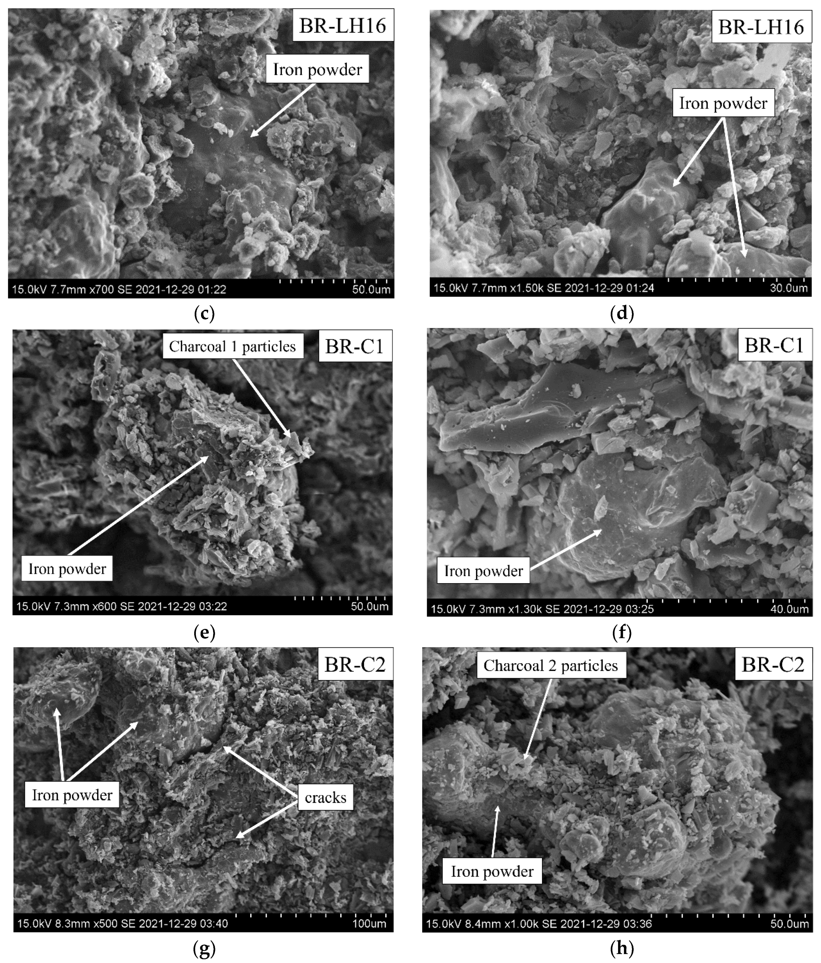
Photographs of BR-LH16 and BR-C2 are shown in Figure 5. BR-LH20 had similar appearance to BR-LH16 and BR-C1 was similar to BR-C2, thus, their photographs are not shown to avoid duplication. The morphologies of the briquettes’ fracture surfaces are shown in Figure 6.
The differences in CCS and drop test performance of briquettes appeared to be closely correlated with the briquette’s appearance at both the macroscale and microscale. The photograph of BR-LH16 revealed a smooth surface, which was also observed from hydrochar pellets produced by Liu et al. [46]. This not only indicates a high degree of compaction of particles in hydrochar briquettes, but also implies that hydrochar is an effective solid lubricant to minimize friction during ejection of the briquette from the mold to avoid surface crack formation [18]. SEM images of BR-LH20 and BR-LH16 showed that hydrochar particles formed smooth, compact matrices with a small amount of voids, which is in agreement with findings by other researchers [44,45,48,50]. Iron particles were evenly distributed in the hydrochar matrices, indicating that hydrochar powder has good flowability and it rearranged rapidly during briquetting to fill up the gaps between iron particles to “glue” them together. The deep indents created by iron particles in the hydrochar matrices indicate strong mechanical interlocking between hydrochar and iron particles, which contributed to the overall high CCS of both hydrochar briquettes. The addition of the 4 wt% binder in BR-LH16 further reduced the micro-voids between fine hydrochar particles, which could be noticed by comparing Figure 6b,d. The median particle size of binder (d50: 11.39 µm) was less than half of that of hydrochar (d50: 29.88 µm). Thus, the binder could fill up the voids between hydrochar particles to improve connection between particles and increase contact area between particles for bonding. This was likely the reason for better drop test performance of BR-LH16 compared to BR-LH20 after the seventh drop.
Contrary to hydrochar briquettes, BR-C2 already showed obvious surface cracks along the horizontal direction immediately after briquetting (Figure 5b). One possible cause of these cracks could be due to too high briquetting pressure used in the present study (155 MPa). Hu et al. [40] explained that increasing pelleting pressure of charcoal below the optimal point of 128 MPa leads to improvement in mechanical strength of the pellets as the particles are brought closer together by the pelleting force. However, the pellet strength decreased when the pelleting pressure exceeded 128 MPa. The decrease in briquette strength was likely caused by a sudden dilatation in the pellet due to reversal of plastic deformation in the charcoal, which led to formation of fractures and splits. Cracks were also observed in between clusters of charcoal particles within the briquette on a micro-scale from the SEM images, for example, in Figure 6g. Similar cracks could also be observed from high magnification SEM images of charcoal pellets in [36]. These cracks enable relative movement of the particles within the briquette [45], which leads to lowered briquette strength.
Comparing BR-LH16, BR-C1, and BR-C2, all containing 4 wt% binder, BR-LH16 had superior mechanical strength compared to the other two briquettes. This indicates that the difference was not caused by the binder. All carbon materials were dried prior to briquetting, and thus the difference in moisture level of briquettes was not an influencing factor. Lemon Hydrochar particles had larger PSD (d50: 29.88 µm) than Charcoal 1 (d50: 18.66 µm) and Charcoal 2 (d50: 10.04 µm). Finer PSD implies less voids in the briquette, shorter interparticle distances, and larger contact areas between particles for bonding. Thus, charcoal briquettes are expected to possess higher strengths than hydrochar briquettes, which contradicts the present observations. One possible explanation is that hydrochar particles have high plasticity and they underwent large plastic deformation during briquetting. On the contrary, charcoal particles fractured into finer ones upon a critical applied load. The void filling effect of deformable hydrochar particles was more pronounced than broken charcoal particles, which resulted in its lower briquette porosity and higher briquette strength. Another explanation is that the bonding strength between hydrochar particles is much higher than those between charcoal particles, such that this effect overrides the influence from PSD.
During HTC, degradation of biomass components (carbohydrates, lipid, lignin) produces large amount of bio-oil, which deposits on the surface of hydrochar. These oily compounds can form a liquid bridge between hydrochar particles and bind them together with capillary force [46]. Hoekman et al. [47] reported a 54% decrease in swelling of wood pellets after adding 22 wt% acetone extractives of hydrochar produced from Tahoe Mix wood. The authors reported insignificant change in pellet durability produced from the hydrochar before and after acetone extraction. This indicated that both the acetone extractives and undissolved components of hydrochar in acetone could operate as a binder. The authors explained that this could be due to the fact that during the HTC process, intermediate chemicals, such as furfural and 5-hydroxymethyl furfural (5-HMF), were generated. These chemicals subsequently cross-linked, aromatized, and polymerized to form furan resins and phenolic resins, which then precipitated as a part of hydrochar. These resins are common adhesives and strengtheners for engineered wood products, which contribute to the excellent binding properties of hydrochar. It is known that furan derivatives—furfurals and 5-HMF—are generated from hydrolysis and dehydration of carbohydrate components in the biomass, such as cellulose and hemicellulose, during HTC [59]. Lemon peels are rich in carbohydrates. Lemon peel consists of cellulose (23.1 wt%), pectin (13.0 wt%), hemicellulose (8.1 wt%), and sugars (6.5 wt%). The remains consist of lignin, protein, fat, polyphenolics, and other extractives [60]. Therefore, large amounts of furan derivates and furan resins are expected to form during HTC of lemon peels, which might explain the strong bonding capability of Lemon Hydrochar in this study. On the contrary, bio-oil generated from degradation of wood components is released as vapor during pyrolysis of woody biomass. It has been reported that bio-oil (tar) represented up to 30% of charcoal’s weight after pyrolysis up to 400–500 °C, which is trapped in the wood structure [61]. The tar could be driven off by further increasing the pyrolysis temperature above 500 °C [61]. However, no tar compounds were discovered from pyrolysis of Charcoal 1 and Charcoal 2 up to 1200 °C in the other part of this work [51]. Thus, it could be inferred that both charcoals had very little or no deposited bio-oil on the surface that could act as binder during briquetting.
Liu et al. [46] proposed that the polar functional groups on the surface of hydrochars could enhance particle attraction force, such as hydrogen bonds and van der Waal’s force. Common polar functional groups contain oxygen, such as hydroxyl, carboxyl, and carbonyl groups. Lemon Hydrochar had significantly higher oxygen concentration (26.8 wt%) than Charcoal 1 (6.5 wt%) and Charcoal 2 (4.2 wt%), which implies larger amount of oxygen-containing polar functional groups in hydrochar compared to both charcoals. This might be another explanation of higher bonding strength among hydrochar particles compared to the two charcoals.
Finer PSD did not improve charcoal briquette’s strength since the drop test performance of BR-C1, which consisted of coarser Charcoal 1 powder, was better than BR-C2, made from finer Charcoal 2 powder. One reason could be that the starch that had been added in Charcoal 1 during densification process acted as an additional binder for BR-C1 (1.7 wt% in Charcoal 1 [51]). Another reason could be that since Charcoal 2 has a lower density than Charcoal 1, there would be a greater number of particles of Charcoal 2 in BR-C2 than Charcoal 1 in BR-C1 given the same weight of charcoal powder in both briquettes. However, as discussed above, the bonding between charcoal particles was very weak and stronger bonding was only developed at connections with binder particles. Given that the amount of binder particles was approximately the same in both charcoal briquettes, there were more charcoal particles in BR-C2 that were unattached to the binder than in BR-C1. This could have led to a worse drop test performance of BR-C2 compared to BR-C1.
Following the above discussion, it could be concluded that: (1) hydrochar is a strong binder, and possible reasons could be that it contains chemical compounds similar to engineering adhesives and that its surface is covered with bio-oil, which could form a strong liquid bridge to bond particles together during briquetting. (2) The effect of bond strength between particles was more important than PSD in the present work. (3) The briquetting pressure (155 MPa) for charcoal briquettes may have been too high, which resulted in reversal of plastic deformation that caused the briquettes to split. (4) Due to the lack of an inherent binder in charcoal particles, binder addition is critically important to increase charcoal briquette strength. The percentage of added binder needs to be significantly increased above 4 wt%. This agrees with findings in previous studies, where a large amount of water (up to 35 wt% [40]) or other binder [39] needed to be added to obtain adequate pellet strength. Although the good agglomeration properties of hydrochar and poor agglomeration of biochar are well known in the literature, the exact mechanism causing this difference has not been clarified up to this date. Thus, it should be investigated in future studies.

3.3. Carburization Experiments

The carbon concentrations in melt samples S0, S1, S2, and S3 are plotted as function of time from the moment S0 was sampled (t = 0 s) and are shown in Figure 7a. After charging of briquettes, the carbon concentrations in the melt increased rapidly, except for the case of BR-C2. The carbon concentration of melt stabilized after 30 s from charging of briquettes. The small fluctuations in melt carbon concentrations after 30 s were due to uncertainties in carbon analysis. The rapid dissolution of charcoal briquettes is in agreement with previous work [33,34]. The increase in carbon concentration of melt from Step 1 (at t = 0 s) and Step 2 of carburization (at t = 30 s) normalized by the weight of briquettes added are shown in Figure 7b.
From Figure 7b, it could be seen that Step 1, in general, yielded a higher increase in melt carbon concentration than Step 2, although there were variations among briquettes. During Step 1, charcoal briquettes carburized the melt more effectively (1.14–1.22 wt%C/kg) than hydrochar briquettes (0.53–0.69 wt%C/kg). In order to achieve the same increase in melt carbon concentration, hydrochar briquettes needed to be added maximum 2.3 times the amount of charcoal briquettes. However, during Step 2, melt carbon concentration increase by both charcoal briquettes deteriorated more than 50% compared to Step 1. The melt carburization by different briquettes during Step 2 were not as distinguished during Step 1. BR-C1 yielded comparable increases in melt carbon concentration (0.55 wt%C/kg) with both hydrochar briquettes (0.52–0.56 wt%C/kg), whereas BR-C2 yielded a slightly lower increase (0.36 wt%C/kg). The deteriorated performance of charcoal briquettes during Step 2 was presumably caused by the weak mechanical strengths of charcoal briquettes. Charcoal briquettes broke into smaller pieces and fine powder upon getting into contact with hot melt, some of which escaped the crucible and resulted in carbon losses. Charcoal briquettes could not withstand the stresses arising from rapid thermal expansion of iron particles and devolatilization of charcoal and binder. Briquette destruction phenomena were also observed with hydrochar briquettes, although the degree was less severe. The total weight of steel melt after Step 2 of carburization could not be measured due to practical reasons, and therefore the amount of briquette losses could not be quantified. Overall, hydrochar briquettes yielded a similar degree of melt carburization during both carburization steps. Charcoal briquettes, however, were very sensitive to the method of addition due to its low mechanical strength.
The above analysis, however, does not provide insight into utilization efficiency of carbon materials since the amount of carbon contained in the same weight of briquettes were different. Lemon Hydrochar has a lower total carbon concentration (59.8 wt%) than both charcoals (86.6–89 wt%), which means that it contains less grams of carbon per gram of char. In addition, Lemon Hydrochar has a low fixed carbon content (26.9 wt%). This means that it loses a significant portion of its weight as well as some carbon through devolatilization when it is slowly heated in an inert atmosphere during Step 1 of carburization. The other part of this work [51] revealed that 54% of total carbon in Lemon Hydrochar is retained in the solid phase after it has been heated up to 1200 °C in a nitrogen atmosphere, whereas 46% of carbon is contained in the volatile matter. On the contrary, both charcoals retain 90% of their initial total carbon contents in the solid phases up to 1200 °C in inert atmosphere. The thermogravimetric analyses of Lemon Hydochar and both charcoals in a nitrogen atmosphere at a heating rate similar to the heating phase during Step 1 of carburization (50 K/min) revealed that the devolatilization of all carbon materials was completed below 950 °C [51] before there was molten EI in the crucible for carbon dissolution. Therefore, the carbon contained in the volatile matter was unlikely to have contributed to melt carburization. Thus, the difference among briquettes during Step 1 of carburization is mostly caused by the difference in the amount of carbon retained in the briquettes after complete devolatilization of carbon materials.
In order to verify this hypothesis and to evaluate the RE of different briquettes and different addition methods, detailed carbon balance calculations were performed for Step 1 and Step 2 of carburization experiments. The results are summarized in Table 6 and Table 7, respectively. The carbon in EI, IP, carbon materials, and the binder in both tables were obtained by multiplying their respective weights in the briquettes by their carbon concentrations given in Table 1. Carbon bound in the solid phase of carbon materials shown in both tables were calculated by multiplying the weight of carbon material in the briquettes by the weight fraction of the solid phase after pyrolysis at 1200 °C and the carbon concentration of the solid phase, which had been evaluated in Part 1 of this work [51]. The carbon distributed in the gas phase was obtained by subtracting total carbon content by the carbon content in the solid phase. The carbon in the binder was not further separated into solid and gas phases since its solid fraction after pyrolysis up to 960 °C was too low (8 wt%), and thus its carbon contribution by carburization was negligible.
REs for both charging methods of briquettes were computed with Equation (1). Regarding the carbon input terms,   M n · C n , only carbon content in the carbon materials and the binder were considered. The carbon bound in EI and IP were assumed to be fully dissolved in the melt. Thus, with the addition of briquettes at room temperature, RE is calculated as
R E 1 = ( W E I + W I P , 1 ) · c 0 ( W E I · c E I + W I P , 1 · c I P ) W C M , 1 · c C M + W b , 1 · c b · 100 %
where W E I , W I P , 1 , W C M , 1 , and W b , 1 are weight of EI, IP, carbon materials (CM), and the binder added initially in Step 1. c 0 , c E I , c I P , c C M , and c b are the carbon concentrations in the steel sample S0, EI, IP, carbon materials, and the binder respectively. For addition of briquettes directly into the melt in Step 2,
R E 2 = ( W E I + W I P , 1 + W I P , 2 ) · c ¯ ( W E I + W I P , 1 )   · c 0 W I P , 2 · c I P W C M , 2 · c C M + W b , 2 · c b · 100 %
where W I P , 2 , W C M , 2 , and W b , 2 denote the weight of IP, carbon materials, and the binder in the added briquettes from Step 2. c ¯ is the averaged carbon concentration of steel samples S1, S2, and S3. The percentage of added carbon in the solid phase was calculated by dividing the grams of carbon in residual char (of carbon materials) by the total added carbon.
From Table 6 and Table 7, it could be observed that the REs of hydrochar were similar during both steps of carburization, which were in the range of 43–54%. This means that 46–57% of carbon in hydrochar was lost to off-gas during carburization, indicating very low utilization efficiency of this material and a large amount of CO2 released. On the contrary, charcoals exhibited very high RE during Step 1 (70–72%) and very low RE during Step 2 (26–39%) of carburization. This implies that the CO2 emissions of charcoal could be minimized by selecting a more suitable method of addition. During Step 1, REs were closely related to the percentage of added carbon in ICBs bound in the solid phase (R2 = 0.972), as shown in Table 6. This supports the hypothesis that the carbon in the volatile matter did not participate in the solid-state carburization reaction, nor in the melt carburization. Lemon Hydrochar and charcoals both released some H2, CO, and CH4 gas below 950 °C [51], which are common carburizing gases for solid steel components [62]. However, the rate of carbon diffusion in solid iron is very sluggish at low temperatures. Thus, carburization is typically performed in a temperature range of 800–1100 °C, with a soaking time of a few hours [62]. In addition, carburizing gases were released from the carbon materials within narrow ranges of temperatures, which corresponded to short soaking time of EI in the released gases. For example, the majority of volatiles in Lemon Hydrochar, Charcoal 1, and Charcoal 2 were released in the temperature ranges of 200–600 °C, 600–950 °C, and 600–750 °C, respectively [51]. With a heating rate of 50 K/min, these temperature ranges corresponded to soaking times of 6.7, 5.8, and 2.5 min respectively, which were too short compared to the typical duration required for solid-state carburization. These factors might explain the lack of contribution of carbon in the volatile matter released by carbon materials in Step 1 of melt carburization.
It is difficult to draw a correlation between REs and percentages of added carbon bound in the solid phase during Step 2 since there were extra carbon losses from briquette destruction in addition to devolatilization of carbon materials. Mourao et al. [63] reported an RE of 77% when adding coal particles (containing 75.1 wt% fixed carbon) directly onto the melt surface for carburization. This RE was much higher than the REs obtained in the present work (26–39%), although the methods of addition were similar and fixed carbon contents of both charcoals were comparable to the coal in their study (Charcoal 1: 77.2 wt%, Charcoal 2: 81.2 wt% [51]). Likewise, Somerville et al. [33] and Baracchini et al. [24] reported REs of 64–83% and 75–80%, respectively, when directly adding charcoal onto the surface of the melt. This suggests that briquette destruction lowered the theoretically achievable RE for both charcoal briquettes in the present study. Mourao et al. [63] also reported that the total volumes of volatile matter detected in the furnace off-gas were 30–59% less when injecting coal particles into the melt compared to devolatilization of the same amount of coal alone. This implies that 40–70% of the volume of volatile gases were retained in the melt. Given that 46% of total carbon in Lemon Hydrochar is contained in the volatile matter [51], 40–70% of carbon in it could be retained in the melt for carburization. Thus, the theoretically achievable RE of hydrochar should be higher than the percentage of the carbon bound in the solid phase. However, Table 7 indicates that the REs of hydrochar briquettes were close to the percentages of added carbon in the solid phase. This could suggest that briquette destruction also impacted the REs of hydrochar briquettes negatively. The maximum carburization potential of charcoal and hydrochar should be further investigated, for example, via direct injection of carbon powder into liquid steel to minimize carbon losses during the addition process.
The REs obtained from addition of briquettes (Step 2) in the present study were compared to the values obtained from carbon dissolution experiments in the literature. The results are shown in Figure 8.
It could be observed that the REs for charcoal briquettes in the present work were lower than values reported by Robinson et al. [34] who also performed charging of iron–carbon briquettes into melt. The differences could be attributed to the fact that they used the fixed carbon content instead of total carbon of carbon materials for evaluation of C n in Equation (1), and they did not include the binder in carbon input. The REs of charcoal briquettes in this work were even lower than the values reported for carbon materials with high volatile matter contents, such as torrefied biomasses and palm kernel shells. This further emphasizes the importance of briquette strength for direct charging into the melt for minimization of briquette losses. The REs of hydrochar briquettes obtained in this work are similar to those of torrefied biomasses with similar amounts of volatile matter. Overall, the REs of hydrochar and charcoal briquettes obtained in this work were significantly lower than values reported for fossil-based recarburizers, such as graphite and anthracite. There appears to be room for improvement of charcoal’s RE just based on optimization of methods of addition, given that other authors have reported higher REs in the range of 64–83%. For hydrochar, it appears that its RE for melt carburization could be further improved by the slow pyrolysis and partial removal of volatile matter content. The RE of pyrolyzed hydrochar should be investigated in the future to confirm the effectiveness of this measure.

4. Conclusions

Iron–carbon briquettes were prepared in a laboratory scale from a mixture that consisted of iron powder (80%), three different types of biomass-based carbonaceous materials (Charcoal 1, pyrolyzed at 500 °C; Charcoal 2, pyrolyzed at 750 °C; and Hydrochar produced from lemon peel), and a binder (0–4 wt%) for use as a recarburizer for liquid steel. The mechanical properties of the briquettes were evaluated by cold compressive stress tests and drop tests, and the briquettes’ fracture surfaces were examined with a scanning electron microscope. Carburization with briquettes was performed in a two-step process: (1) firstly, by adding four 100 g briquettes together with 10 kg electrolytic iron in an alumina crucible and heating them from room temperature up to 1600 °C, (2) followed by charging four 100 g briquettes into the 1600 °C melt. The following specific conclusions can be made based on the results of this study:
  • The briquette with a mixture of 20% hydrochar and 80% iron powder had excellent mechanical properties with cold compressive stress > 16 MPa and survived seven drops from 1.0 m above ground. By adding a 4% plastic-based binder to the hydrochar briquette, the weight loss during the drop test was further decreased. Hydrochar has great potential to be used as an organic binder.
  • Briquettes that consisted of charcoal, iron powder, and 4% binder had very low cold compressive stress and were easily destroyed during drop tests. Therefore, the briquette recipe should be further optimized in the future
  • The recarburization efficiencies from the first stage of carburization were in the order of Charcoal 2 briquette (72.4% for BR-C2) > Charcoal 1 briquette (69.8% for BR-C1) > Hydrochar briquette without binder (57.7% for BR-LH20) > Hydrochar briquette with binder (43.3% for BR-LH16). Only carbon contained in the solid up to a high temperature (1200 °C) could be eventually dissolved in the melt.
  • The recarburization efficiencies from the second stage (addition of briquettes in the melt at 1600 °C) were in the following order: Hydrochar briquette without binder (53.5% for BR-LH20) > Hydrochar briquette with binder (48.3% for BR-LH16) > Charcoal 1 briquette (38.7% for BR-C1) > Charcoal 2 briquette (26.4% for BR-C2). Low efficiency of charcoal briquettes was associated with briquette losses from rapid briquette destruction upon contact with the hot melt.
  • The volatile matter in hydrochar was not utilized effectively during both stages of carburization. A preliminary slow pyrolysis of hydrochar can be performed to remove volatile matter and use it for other purpose.

Author Contributions

Conceptualization, Y.-C.L.; methodology, Y.-C.L.; validation, Y.-C.L., A.V.K. and C.W.; formal analysis, Y.-C.L.; investigation, Y.-C.L. and A.V.K.; writing—original draft preparation, Y.-C.L. and A.V.K.; writing—review and editing, A.V.K., L.B. and C.W.; supervision, A.K; project administration, C.W. All authors have read and agreed to the published version of the manuscript.

Funding

This research was funded by VINNOVA (Swedish governmental Agency for Innovation Systems) and some of the participating companies in OSMET 3.0 project (dnr: 2020-04140).

Acknowledgments

We would like to thank Ingelia for providing us Lemon Hydrochar for experiments.

Conflicts of Interest

The authors declare no conflict of interest.

References

  1. Suopajärvi, H.; Kemppainen, A.; Haapakangas, J.; Fabritius, T. Extensive review of the opportunities to use biomass-based fuels in iron and steelmaking processes. J. Clean. Prod. 2017, 148, 709–734. [Google Scholar] [CrossRef]
  2. Mousa, E.; Wang, C.; Riesbeck, J.; Larsson, M. Biomass applications in iron and steel industry: An overview of challenges and opportunities. Renew. Sustain. Energy Rev. 2016, 65, 1247–1266. [Google Scholar] [CrossRef]
  3. The World Bank Group. Carbon Pricing Dashboard. Available online: https://carbonpricingdashboard.worldbank.org/map_data (accessed on 28 February 2022).
  4. Wiklund, C.-M.; Helle, M.; Saxén, H. Economic assessment of options for biomass pretreatment and use in the blast furnace. Biomass Bioenergy 2016, 91, 259–270. [Google Scholar] [CrossRef]
  5. Wei, R.; Zhang, L.; Cang, D.; Li, J.; Li, X.; Xu, C.C. Current status and potential of biomass utilization in ferrous metallurgical industry. Renew. Sustain. Energy 2017, 68, 511–524. [Google Scholar] [CrossRef]
  6. Suopajärvi, H.; Pongrácz, E.; Fabritius, T. The potential of using biomass-based reducing agents in the blast furnace: A review of thermochemical conversion technologies and assessments related to sustainability. Renew. Sustain. Energy Rev. 2013, 25, 511–528. [Google Scholar] [CrossRef]
  7. Echterhof, T. Review on the Use of Alternative Carbon Sources in EAF Steelmaking. Metals 2021, 11, 222. [Google Scholar] [CrossRef]
  8. Fraga, M.; Flores, B.; Osório, E.; Vilela, A. Evaluation of the thermoplastic behavior of charcoal, coal tar and coking coal blends. J. Mater. Res. Technol. 2020, 9, 3406–3410. [Google Scholar] [CrossRef]
  9. Aziz, H.; Rodrigues, S.; Esterle, J.S.; Steel, K.M. Interactions between vitrinite and solid additives including inertinite during pyrolysis for coke-making considerations. Fuel Processing Technol. 2020, 201, 106321. [Google Scholar] [CrossRef]
  10. Guerrero, A.; Diez, M.A.; Borrego, A.G. Influence of charcoal fines on the thermoplastic properties of coking coals and the optical properties of the semicoke. Int. J. Coal Geol. 2015, 147–148, 105–114. [Google Scholar] [CrossRef] [Green Version]
  11. Riva, L.; Nielsen, H.K.; Skreiberg, Ø.; Wang, L.; Bartocci, P.; Barbanera, M.; Bidini, G.; Fantozzi, F. Analysis of optimal temperature, pressure and binder quantity for the production of biocarbon pellet to be used as a substitute for coke. Appl. Energy 2019, 256, 113933. [Google Scholar] [CrossRef]
  12. Kamal Baharin, N.S.; Koesoemadinata, V.C.; Nakamura, S.; Yahya, W.J.; Muhammad Yuzir, M.A.; Md Akhir, F.N.; Iwamoto, K.; Othman, N.A.; Ida, T.; Hara, H. Conversion and characterization of Bio-Coke from abundant biomass waste in Malaysia. Renew. Energy 2020, 162, 1017–1025. [Google Scholar] [CrossRef]
  13. Wang, C.; Mellin, P.; Lövgren, J.; Nilsson, L.; Yang, W.; Salman, H.; Hultgren, A.; Larsson, M. Biomass as blast furnace injectant—Considering availability, pretreatment and deployment in the Swedish steel industry. Energy Convers. Manag. 2015, 102, 217–226. [Google Scholar] [CrossRef] [Green Version]
  14. Solar, J.; Hippe, F.; Babich, A.; Caballero, B.M.; de Marco Rodríguez, I.; Barriocanal, C.; López-Urionabarrenechea, A.; Acha, E. Conversion of Injected Forestry Waste Biomass Charcoal in a Blast Furnace: Influence of Pyrolysis Temperature. Energy Fuels 2021, 35, 529–538. [Google Scholar] [CrossRef]
  15. Lovel, R.; Vining, K.; Dell’Amico, M. Iron ore sintering with charcoal. Miner. Process. Extr. Metall. 2007, 116, 85–92. [Google Scholar] [CrossRef]
  16. Cheng, Z.; Yang, J.; Zhou, L.; Liu, Y.; Wang, Q. Characteristics of charcoal combustion and its effects on iron-ore sintering performance. Appl. Energy 2016, 161, 364–374. [Google Scholar] [CrossRef]
  17. Ooi, T.C.; Thompson, D.; Anderson, D.R.; Fisher, R.; Fray, T.; Zandi, M. The effect of charcoal combustion on iron-ore sintering performance and emission of persistent organic pollutants. Combust. Flame 2011, 158, 979–987. [Google Scholar] [CrossRef]
  18. Mousa, E.; Kazemi, M.; Larsson, M.; Karlsson, G.; Persson, E. Potential for Developing Biocarbon Briquettes for Foundry Industry. Appl. Sci. 2019, 9, 5288. [Google Scholar] [CrossRef] [Green Version]
  19. Jarnerud, T.; Karasev, A.; Wang, C.; Bäck, F.; Jönsson, P. Utilization of Organic Mixed Biosludge from Pulp and Paper Industries and Green Waste as Carbon Sources in Blast Furnace Hot Metal Production. Sustainability 2021, 13, 7706. [Google Scholar] [CrossRef]
  20. Kowitwarangkul, P.; Babich, A.; Senk, D. Reduction Behavior of Self-Reducing Pellet (SRP) for Low Height Blast Furnace. Steel Res. Int. 2014, 85, 1501–1509. [Google Scholar] [CrossRef]
  21. Konishi, H.; Ichikawa, K.; Usui, T. Effect of Residual Volatile Matter on Reduction of Iron Oxide in Semi-charcoal Composite Pellets. ISIJ Int. 2010, 50, 386–389. [Google Scholar] [CrossRef] [Green Version]
  22. Skoczkowski, T.; Verdolini, E.; Bielecki, S.; Kochański, M.; Korczak, K.; Węglarz, A. Technology innovation system analysis of decarbonisation options in the EU steel industry. Energy 2020, 212, 118688. [Google Scholar] [CrossRef] [PubMed]
  23. Luh, S.; Budinis, S.; Schmidt, T.J.; Hawkes, A. Decarbonisation of the Industrial Sector by means of Fuel Switching, Electrification and CCS. In Computer Aided Chemical Engineering; Friedl, A., Klemeš, J.J., Radl, S., Varbanov, P.S., Wallek, T., Eds.; Elsevier: Amsterdam, The Netherlands, 2018; Volume 43, pp. 1311–1316. [Google Scholar]
  24. Baracchini, G.; Bianco, L.; Cirilli, F.; Echterhof, T.; Griessacher, T.; Marcos, M.; Mirabile, D.; Reichel, T.; Rekersdrees, T.; Sommerauer, H. Biochar for a Sustainable EAF Steel Production (GREENEAF2); Publications Office of the European Union: Luxembourg, 2018. [Google Scholar]
  25. Bianco, L.; Baracchini, G.; Cirilli, F.; Sante, L.D.; Moriconi, A.; Moriconi, E.; Agorio, M.M.; Pfeifer, H.; Echterhof, T.; Demus, T.; et al. Sustainable Electric Arc Furnace Steel Production: GREENEAF. BHM Berg Hüttenmännische Mon. 2013, 158, 17–23. [Google Scholar] [CrossRef]
  26. Cirilli, F.; Baracchini, G.; Bianco, L. EAF long term industrial trials of utilization of char from biomass as fossil coal substitute. Metall. Ital. 2017, 109, 13–17. [Google Scholar]
  27. Huang, X.-A.; Ng, K.W.; Giroux, L.; Duchesne, M. Carbonaceous Material Properties and Their Interactions with Slag During Electric Arc Furnace Steelmaking. Metall. Mater. Trans. B 2019, 50, 1387–1398. [Google Scholar] [CrossRef]
  28. Yunos, N.F.M.; Zaharia, M.; Idris, M.A.; Nath, D.; Khanna, R.; Sahajwalla, V. Recycling Agricultural Waste from Palm Shells during Electric Arc Furnace Steelmaking. Energy Fuels 2012, 26, 278–286. [Google Scholar] [CrossRef]
  29. Fidalgo, B.; Berrueco, C.; Millan, M. Chars from agricultural wastes as greener fuels for electric arc furnaces. J. Anal. Appl. Pyrolysis 2015, 113, 274–280. [Google Scholar] [CrossRef]
  30. Yunos, N.F.M.; Ahmad, K.R.; Zaharia, M.; Sahajwalla, V. Combustion of Agricultural Waste and Coke Blends during High Temperature Processes: Effect of Physical, Chemical and Surface Properties. J. Jpn. Soc. Exp. Mech. 2011, 11, s261–s266. [Google Scholar] [CrossRef]
  31. Mathieson, J.; Rogers, H.; Somerville, M.; Ridgeway, P.; Jahanshahi, S. Use of Biomass in the Iron and Steel Industry—An Australian Perspective. In Proceedings of the 1st International Conference on Energy Efficiency and CO2 Reduction in the Steel Industry (EECR Steel 2011)—Incorporated in METEC InSteelCon 2011, Dusseldorf, Germany, 27 June–1 July 2011; The Steel Institute VDEh: Dusseldorf, Germany, 2011. Available online: http://hdl.handle.net/102.100.100/103943?index=1 (accessed on 28 February 2022).
  32. Rađenović, A.; Kolar, M. Petroleum coke as carburizing material in foundry. Nafta 2004, 55, 409–412. [Google Scholar]
  33. Somerville, M.; Jahanshahi, S.; Ridgeway, P.; Davies, M.; Mathieson, J. Sustainable carbon in steelmaking—Plant trials at the Sydney Steel Mill, Sustainable. In Proceedings of the Sustainable Mining 2010—The Business Case, Kalgoorlie, WA, Australia, 17–19 August 2010; AusIMM: Melbourne, Australia, 2010; pp. 38–52. [Google Scholar]
  34. Robinson, R.; Brabie, L.; Pettersson, M.; Amovic, M.; Ljunggren, R. An Empirical Comparative Study of Renewable Biochar and Fossil Carbon as Carburizer in Steelmaking. ISIJ Int. 2020, advpub. [Google Scholar] [CrossRef]
  35. Janerka, K.; Jezierski, J.; Jan, S. Quality and properties of the cast iron produced on the steel scrap base. Arch. Mater. Sci. Eng. 2012, 53, 92–101. [Google Scholar]
  36. Riva, L.; Surup, G.R.; Buø, T.V.; Nielsen, H.K. A study of densified biochar as carbon source in the silicon and ferrosilicon production. Energy 2019, 181, 985–996. [Google Scholar] [CrossRef]
  37. Mathieson, J.G.; Somerville, M.A.; Deev, A.; Jahanshahi, S. 19—Utilization of biomass as an alternative fuel in ironmaking. In Iron Ore; Lu, L., Ed.; Woodhead Publishing: Sawston, UK, 2015; pp. 581–613. [Google Scholar]
  38. Somerville, M.A.; Mathieson, J.G.; Ridgeway., P.L. Overcoming problems of using charcoal as a substitute for coke in iron and steelmaking operations. In Proceedings of the 42º Seminário de Redução de Minério de Ferro e Matérias-primas/13º Seminário Brasileiro de Minério de Ferro/6th International Congress on the Science and Technology of Ironmaking, Rio de Janeiro, Brazil, 14–18 October 2012. [Google Scholar]
  39. Hu, Q.; Shao, J.; Yang, H.; Yao, D.; Wang, X.; Chen, H. Effects of binders on the properties of bio-char pellets. Appl. Energy 2015, 157, 508–516. [Google Scholar] [CrossRef]
  40. Hu, Q.; Yang, H.; Yao, D.; Zhu, D.; Wang, X.; Shao, J.; Chen, H. The densification of bio-char: Effect of pyrolysis temperature on the qualities of pellets. Bioresour. Technol. 2016, 200, 521–527. [Google Scholar] [CrossRef] [PubMed]
  41. Demus, T.; Echterhof, T.; Pfeifer, H.; Schulten, M.; Quicker, P. Investigations on the Use of Biogenic Residues as a Substitute for Fossil Coal in the Eaf Steelmaking Process. In Proceedings of the 10th European Electric Steelmaking Conference: EEC 2012, Graz, Austria, 25–28 September 2012; The Austrian Society For Metallurgy And Materials (Asmet): Leoben, Austria, 2012; pp. 500–509. [Google Scholar]
  42. Zhou, Y.; Lin, M.; Zhong, M.; Yan, X.; Yang, Y. Molten metal and water direct contact interaction research—I. Photographic experiment study. Ann. Nucl. Energy 2014, 70, 248–255. [Google Scholar] [CrossRef]
  43. Kudo, S.; Mori, A.; Soejima, R.; Murayama, F.; Karnowo; Nomura, S.; Dohi, Y.; Norinaga, K.; Hayashi, J.-i. Preparation of Coke from Hydrothermally Treated Biomass in Sequence of Hot Briquetting and Carbonization. ISIJ Int. 2014, 54, 2461–2469. [Google Scholar] [CrossRef] [Green Version]
  44. Sharma, H.B.; Panigrahi, S.; Dubey, B.K. Hydrothermal carbonization of yard waste for solid bio-fuel production: Study on combustion kinetic, energy properties, grindability and flowability of hydrochar. Waste Manag. 2019, 91, 108–119. [Google Scholar] [CrossRef]
  45. Sharma, H.B.; Dubey, B.K. Binderless fuel pellets from hydrothermal carbonization of municipal yard waste: Effect of severity factor on the hydrochar pellets properties. J. Clean. Prod. 2020, 277, 124295. [Google Scholar] [CrossRef]
  46. Liu, Z.; Quek, A.; Balasubramanian, R. Preparation and characterization of fuel pellets from woody biomass, agro-residues and their corresponding hydrochars. Appl. Energy 2014, 113, 1315–1322. [Google Scholar] [CrossRef]
  47. Hoekman, S.K.; Broch, A.; Warren, A.; Felix, L.; Irvin, J. Laboratory pelletization of hydrochar from woody biomass. Biofuels 2014, 5, 651–666. [Google Scholar] [CrossRef]
  48. Reza, M.T.; Uddin, M.H.; Lynam, J.G.; Coronella, C.J. Engineered pellets from dry torrefied and HTC biochar blends. Biomass Bioenergy 2014, 63, 229–238. [Google Scholar] [CrossRef]
  49. Wu, S.; Zhang, S.; Wang, C.; Mu, C.; Huang, X. High-strength charcoal briquette preparation from hydrothermal pretreated biomass wastes. Fuel Process. Technol. 2018, 171, 293–300. [Google Scholar] [CrossRef]
  50. Cao, Z.; Zhang, S.; Huang, X.; Liu, H.; Sun, M.; Lyu, J. Correlations between the compressive strength of the hydrochar pellets and the chemical components: Evolution and densification mechanism. J. Anal. Appl. Pyrolysis 2020, 152, 104956. [Google Scholar] [CrossRef]
  51. Lu, Y.-C.; Yang, H.M.; Karasev, A.V.; Wang, C. Applications of hydrochar and charcoal in the iron and steelmaking industry- Part 1: Characterization of carbonaceous materials. Sustainability, 2022; Unpublished. [Google Scholar]
  52. Jarnerud, T.; Karasev, A.; Jönsson, P. Briquetting of Wastes from Pulp and Paper Industries by Using AOD Converter Slag as Binders for Application in Metallurgy. Materials 2019, 12, 2888. [Google Scholar] [CrossRef] [PubMed] [Green Version]
  53. Kovačič, M.; Stopar, K.; Vertnik, R.; Šarler, B. Comprehensive Electric Arc Furnace Electric Energy Consumption Modeling: A Pilot Study. Energies 2019, 12, 2142. [Google Scholar] [CrossRef] [Green Version]
  54. Jung, E.; Kim, H.; Yang, H.; Andersson, J.; Kim, K.; Teng, L.; Lee, E. Problems with and Solutions to Skull Formation in EBT Furnace for Tool and Stainless Steel Production. In Proceedings of the Iron & Steel Technology Conference (AISTech 2020), Cleveland, OH, USA, 31 August–3 September 2020; pp. 583–593. [Google Scholar]
  55. Mostafaee, S. A Study of EAF High-Chromium Stainless Steelmaking Slags Characteristics and Foamability. Ph.D. Thesis, KTH Royal Institute of Technology, Stockholm, Sweden, 2011. comprehensive summary. [Google Scholar]
  56. Bazargan, A.; Rough, S.L.; McKay, G. Compaction of palm kernel shell biochars for application as solid fuel. Biomass Bioenergy 2014, 70, 489–497. [Google Scholar] [CrossRef]
  57. Andersson, J.O.; Helander, T.; Höglund, L.; Shi, P.; Sundman, B. Thermo-Calc & DICTRA, computational tools for materials science. Calphad 2002, 26, 273–312. [Google Scholar] [CrossRef]
  58. Arkema Inc. Safety Data Sheet—Orgasol® 3502 D NAT 1. 2017. Available online: https://www.palmerholland.com/getmedia/4b9cfaff-b4a3-46a5-932c-17d1cdff56fe/MITM01773_1 (accessed on 28 February 2022).
  59. Fernández-Sanromán, Á.; Lama, G.; Pazos, M.; Rosales, E.; Sanromán, M.Á. Bridging the gap to hydrochar production and its application into frameworks of bioenergy, environmental and biocatalysis areas. Bioresour. Technol. 2021, 320, 124399. [Google Scholar] [CrossRef]
  60. Pathak, P.D.; Mandavgane, S.A.; Kulkarni, B.D. Fruit peel waste: Characterization and its potential uses. Curr. Sci. 2017, 113, 444–454. [Google Scholar] [CrossRef]
  61. Panwar, N.L.; Kothari, R.; Tyagi, V.V. Thermo chemical conversion of biomass—Eco friendly energy routes. Renew. Sustain. Energy Rev. 2012, 16, 1801–1816. [Google Scholar] [CrossRef]
  62. Edenhofer, B.; Joritz, D.; Rink, M.; Voges, K. 13—Carburizing of steels. In Thermochemical Surface Engineering of Steels; Mittemeijer, E.J., Somers, M.A.J., Eds.; Woodhead Publishing: Oxford, UK, 2015; pp. 485–553. [Google Scholar]
  63. Mourao, M.B.; Murthy, G.G.K.; Elliott, J.F. Experimental investigation of dissolution rates of carbonaceous materials in liquid iron-carbon melts. Metall. Trans. B 1993, 24, 629–637. [Google Scholar] [CrossRef]
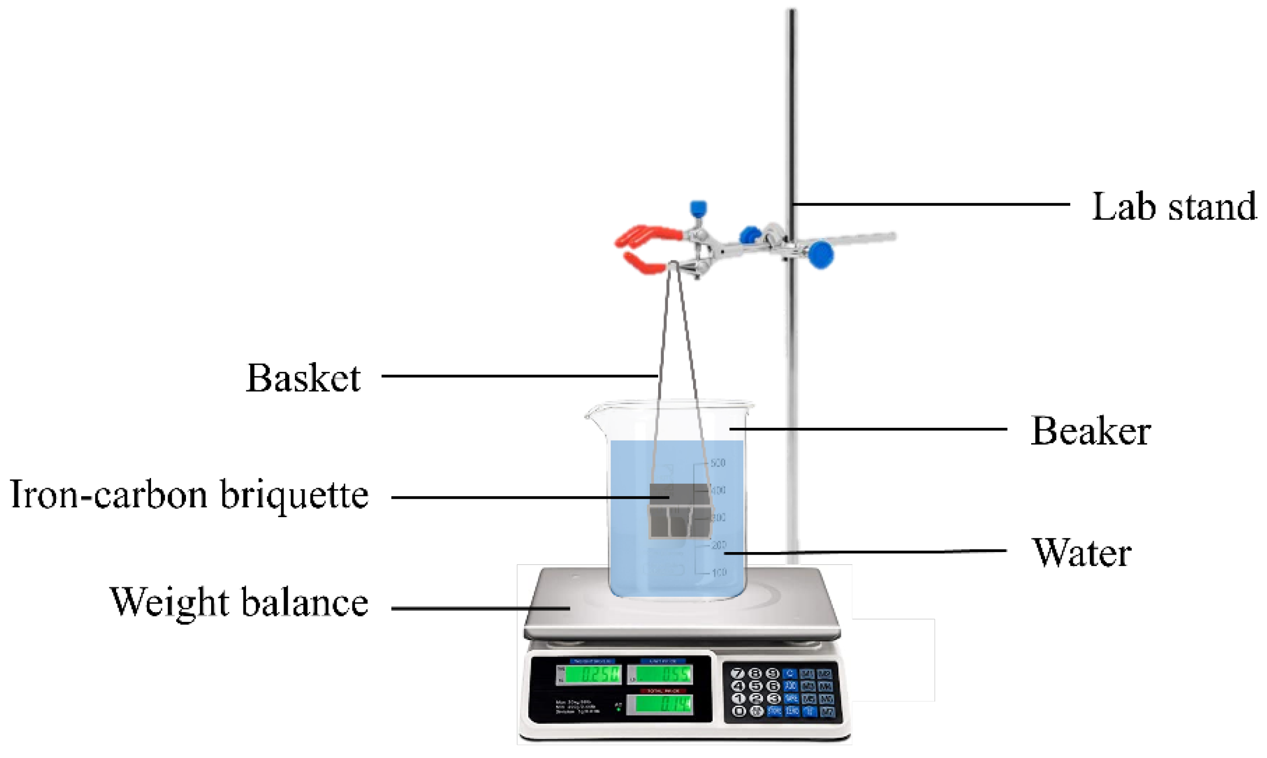
Figure 1. Experimental setup for measurement of apparent densities of briquettes.
Sustainability 14 05383 g001
Figure 2. Experimental details of melt carburization experiments with iron–carbon briquettes: (a) schematic illustration of experimental setup; (b) schematic illustration of experimental procedure.
Sustainability 14 05383 g002aSustainability 14 05383 g002b
Figure 3. Thermogravimetric analysis at heating rate of 50 K/min of the binder in the present study, and Charcoal 1, Charcoal 2, and Lemon Hydrochar taken from [51] at 50 K/min: (a) weight percentage versus temperature; (b) weight loss rate versus temperature.
Sustainability 14 05383 g003
Figure 4. Drop test results of iron–carbon briquettes.
Sustainability 14 05383 g004
Figure 5. Photographs of iron–carbon briquettes for: (a) BR-LH16; (b) BR-C2.
Sustainability 14 05383 g005
Figure 6. SEM images of fracture surfaces of iron–carbon briquettes of: (a,b) BR-LH20; (c,d) BR-LH16; (e,f) BR-C1; (g,h) BR-C2.
Sustainability 14 05383 g006aSustainability 14 05383 g006b
Figure 7. (a) Carbon concentration evolution in liquid steel samples S0, S1, S3, and S4 taken during carburization experiments; (b) melt carbon concentration increase during Step 1 and Step 2 of carburization normalized by the weight of briquette added in each step.
Sustainability 14 05383 g007
Figure 8. Recarburization efficiency obtained in the present work and comparison with values reported in literature [24,33,34].
Sustainability 14 05383 g008
Table 1. Proximate and ultimate analysis of carbonaceous materials and binder (for making of briquettes) (in weight percentages).
MaterialCharcoal 1Charcoal 2Lemon
Hydrochar
Binder
Proximate analysis (db 1)
Volatile matter 19.711.467.0NA 2
Ultimate analysis (db 1)
C86.689.059.867.1
H1.80.55.711.0
N0.570.611.4511.61
O6.54.226.810.3
S0.0290.0700.0740.037
Others (by difference)4.5005.6206.1760.003
1 db = dry basis. 2 NA = not analyzed.
Table 2. Chemical compositions of iron powder and electrolytic iron (in weight percentages).
CSPSiMnCrNiCuMoSnCa
Iron powder0.0100.0080.00260.0010.0640.0260.0140.0120.0010.0020.003
Electrolytic iron0.0070.0040.00300.0540.0300.0160.013<0.001<0.001<0.001NA
Table 3. Recipes of iron–carbon briquettes.
Briquette IDType of Carbon MaterialPercentage of Carbon
Materials (%)
Percentage of Iron Powder (%)Percentage of Binder (%)
BR-LH20Lemon Hydrochar20800
BR-LH16Lemon Hydrochar16804
BR-C1Charcoal 116804
BR-C2Charcoal 216804
Table 6. Carbon balance for Step 1 of carburization experiments by charging of briquettes at room temperature.
BR-LH20BR-LH16BR-C1BR-C2
Total weight of EI (g)10,000.00
Total weight of briquettes393.20398.18377.34299.30
   Weight of IP in briquettes (g)314.56318.54301.87239.44
   Weight of carbon materials in briquettes (g)78.6463.7160.3747.89
   Weight of binder in briquettes (g)0.015.9015.112.0
Carbon in EI (g)0.7
Carbon in IP (g)0.030.030.030.02
Total carbon in carbon materials (g)47.0338.1052.2842.62
   Carbon in residual char (solid) (g)25.5720.7246.9838.51
   Carbon in volatile matter (gas) (g)21.4517.385.314.11
Total carbon content in binder (g)0.0010.6910.138.03
Total added carbon excluding EI, IP(g)47.0348.7962.4150.65
Dissolved carbon in melt (g)27.1221.1543.5736.67
Percentage of added carbon in solid phase (%)54.3842.4775.2776.02
Recarburization efficiency (%)57.6745.3469.8772.40
Table 7. Carbon balance for Step 2 of carburization experiments by addition of briquettes into 1600 °C melt.
BR-LH20BR-LH16BR-C1BR-C2
Total weight of EI (g)0.00
Total weight of briquettes397.94397.58384.67170.60
   Weight of IP in briquettes (g) 318.35318.06307.74136.48
   Weight of carbon materials in briquettes (g)79.5963.6161.5527.30
   Weight of binder in briquettes (g)0.015.9015.396.82
Carbon in EI (g)0.00
Carbon in IP (g)0.030.030.030.01
Total carbon in carbon materials (g)47.5938.0453.3024.29
   Carbon in residual char (g)25.8820.6947.8921.95
   Carbon in volatile matter (g)21.7117.355.412.35
Total carbon content in binder (g)0.0010.6710.324.58
Total added carbon excluding EI, IP (g)47.5948.7163.6228.87
Dissolved carbon in melt (g)25.4523.5324.657.61
Percentage of added carbon in solid phase (%)54.3842.4775.2776.02
Recarburization efficiency (%)53.4748.3038.7426.37
Publisher’s Note: MDPI stays neutral with regard to jurisdictional claims in published maps and institutional affiliations.