
A Battery-Free Sustainable Powertrain Solution for Hydrogen Fuel Cell City Transit Bus Application


Abstract
:1. Introduction
2. System Architecture and Modelling
2.1. System Architecture
- A dynamically controlled FC stack, where the stack power setting is regulated as a function of the vehicle demanded power, with the drawback that the stack needs to be sized at the peak vehicle power. Moreover, considering that FC efficiency strongly depends on its operating point, the FC works at low efficiency where the required power load is fluctuating.
- A static controlled FC stack, where the FC is kept at a constant operating point close to the maximum efficiency one. The transient power is managed by the energy storage system (ESS), which requires significant storage capability.
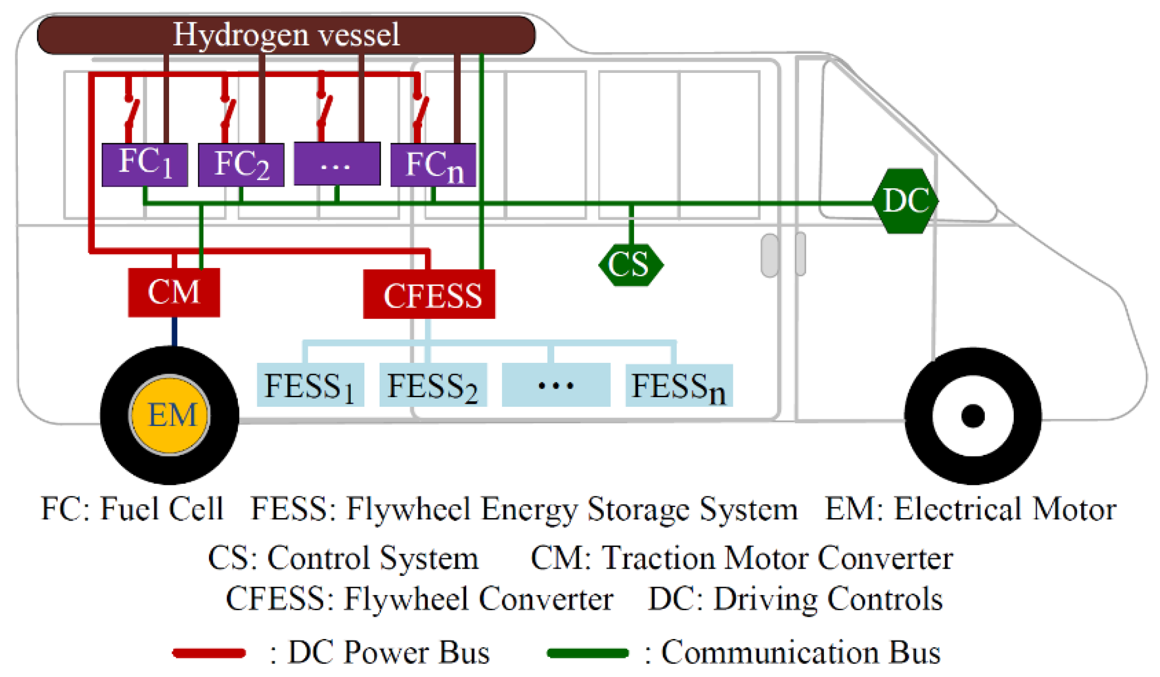
- providing power when the load power is higher than the FC power.
- recovering when the FC power is higher than the load power and during the regenerative electrical braking. The schematic of the hybrid powertrain and the reference directions of the power flows are shown in Figure 2.
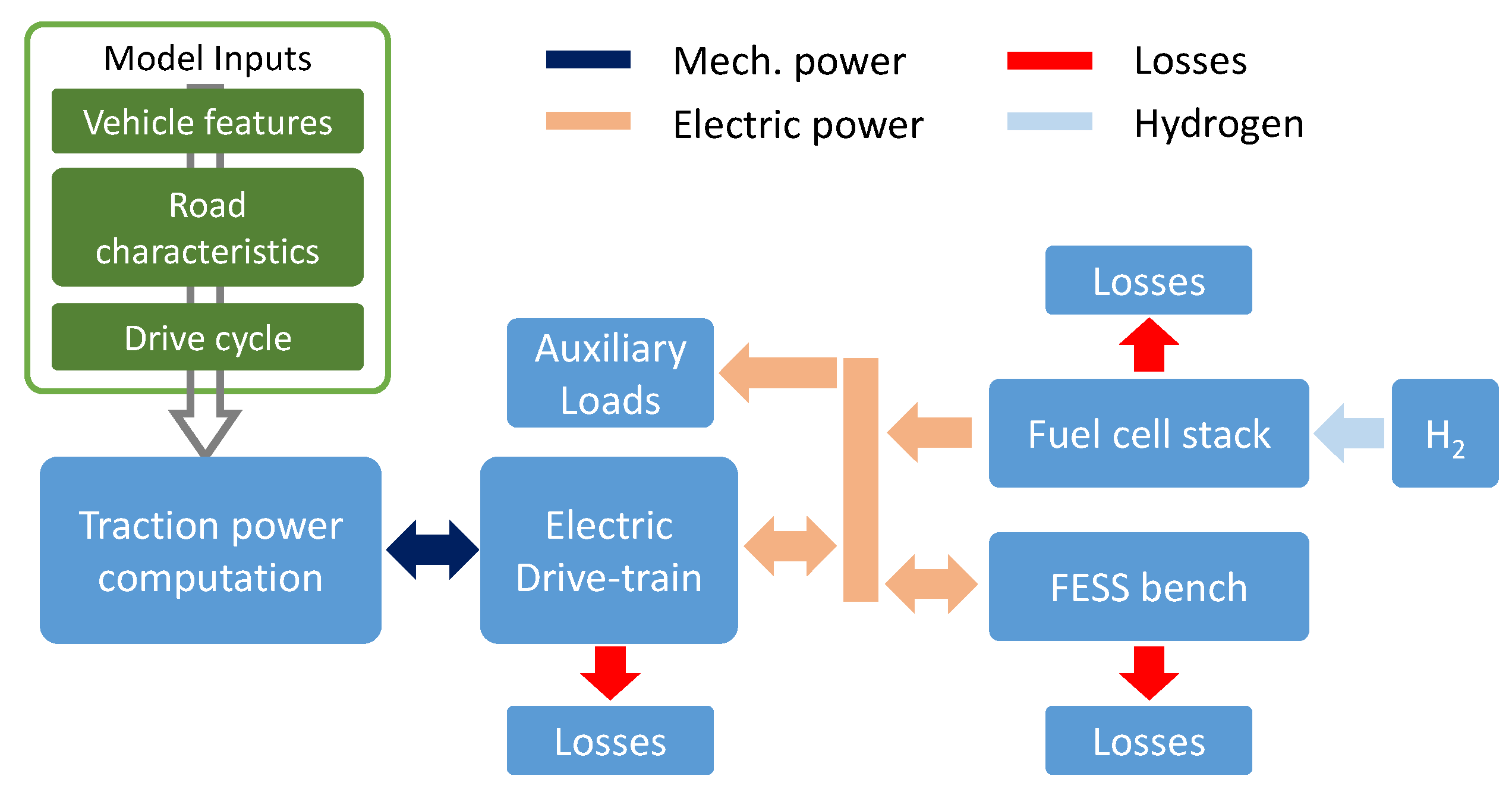
2.2. Model-Based Approach
- “Vehicle”, addressing the vehicle (mass, dimensions, mechanics, efficiency, payload, etc.);
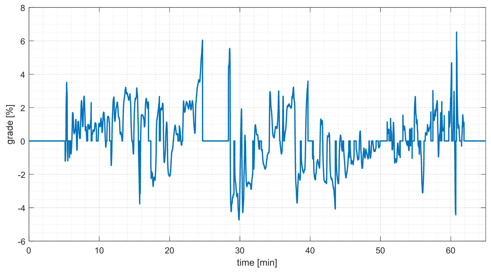
- “Road”, concerning the topography of the path and the road surface characteristics;
- “Drive Cycle”, describing the demanded driving profile by specifying the velocity vs. time;
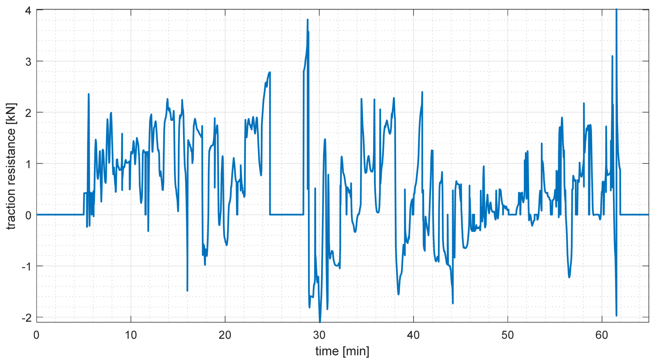
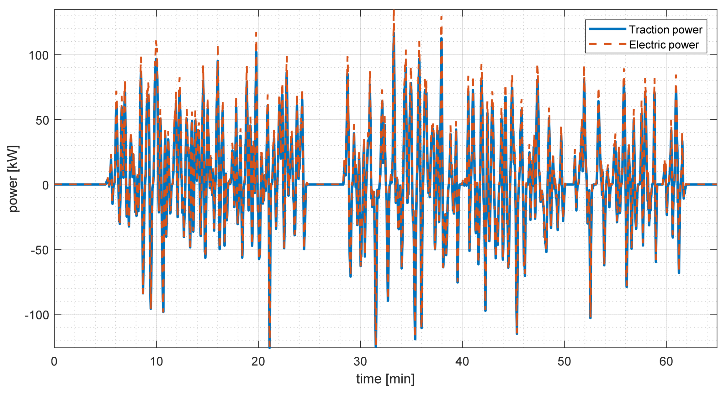
- The “Traction power” block computes the mechanical power needed to drive over the input path with the selected vehicle at the specified speed profile.
3. Application Case
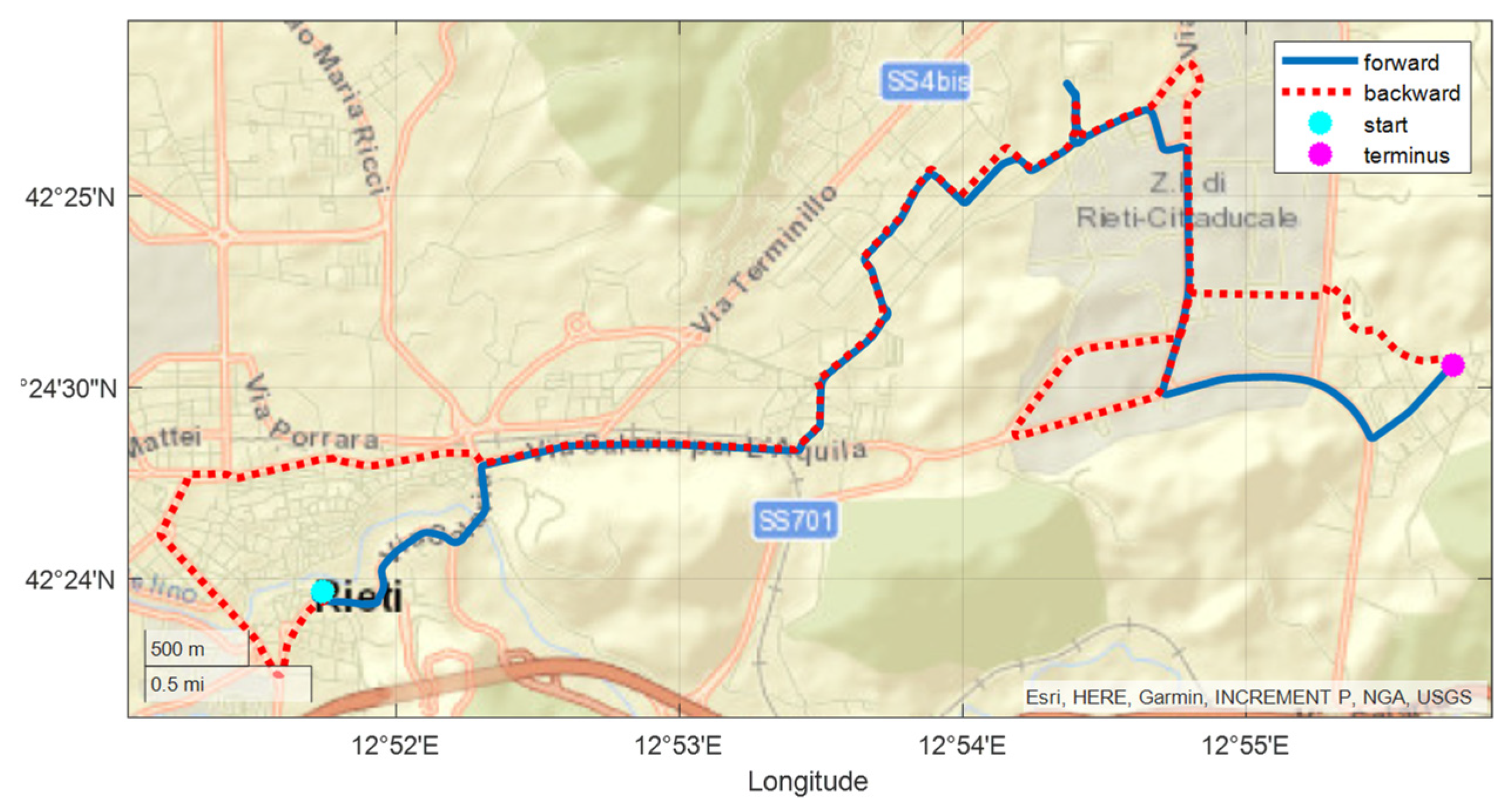
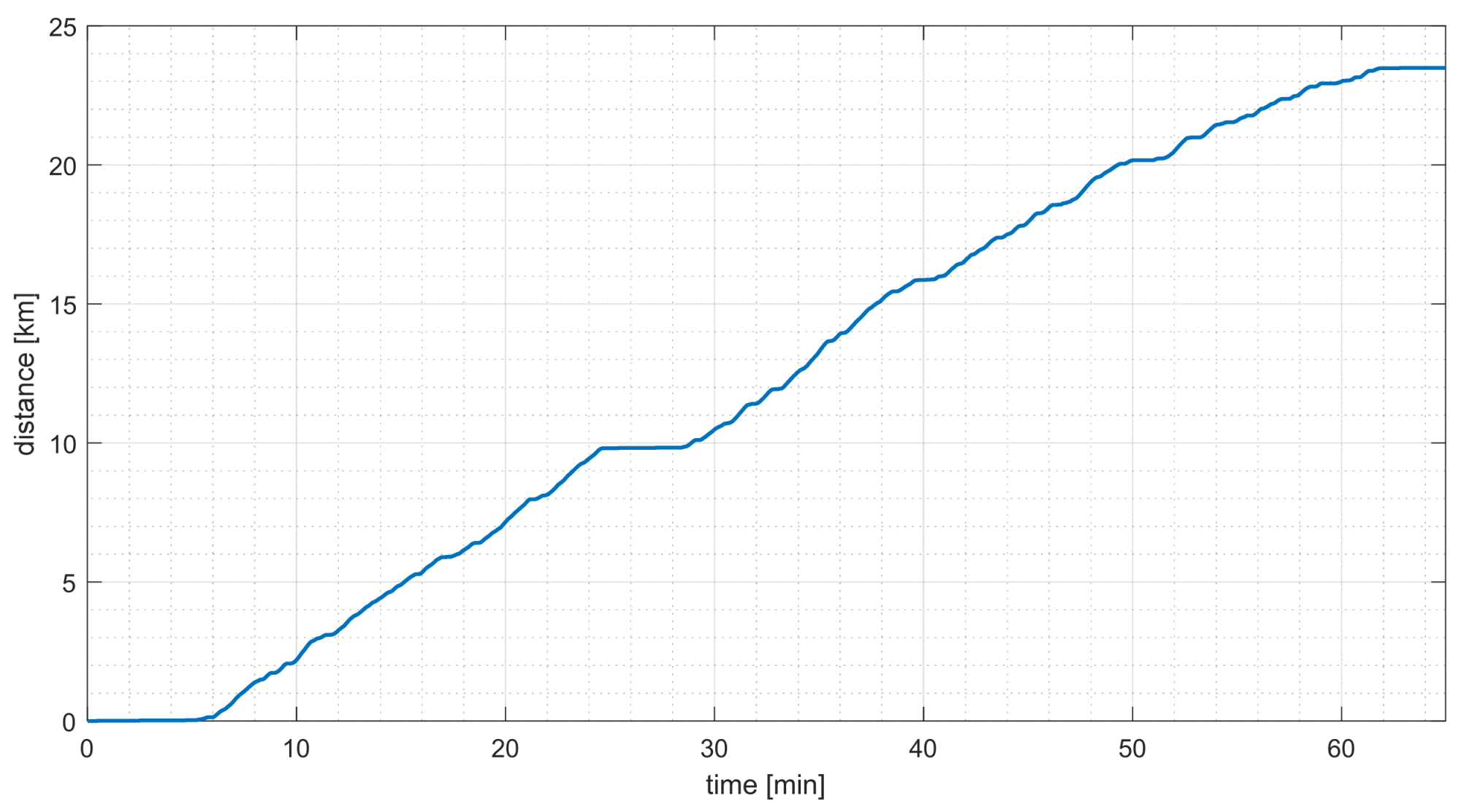
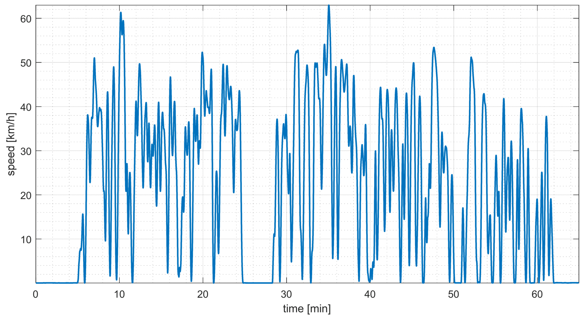
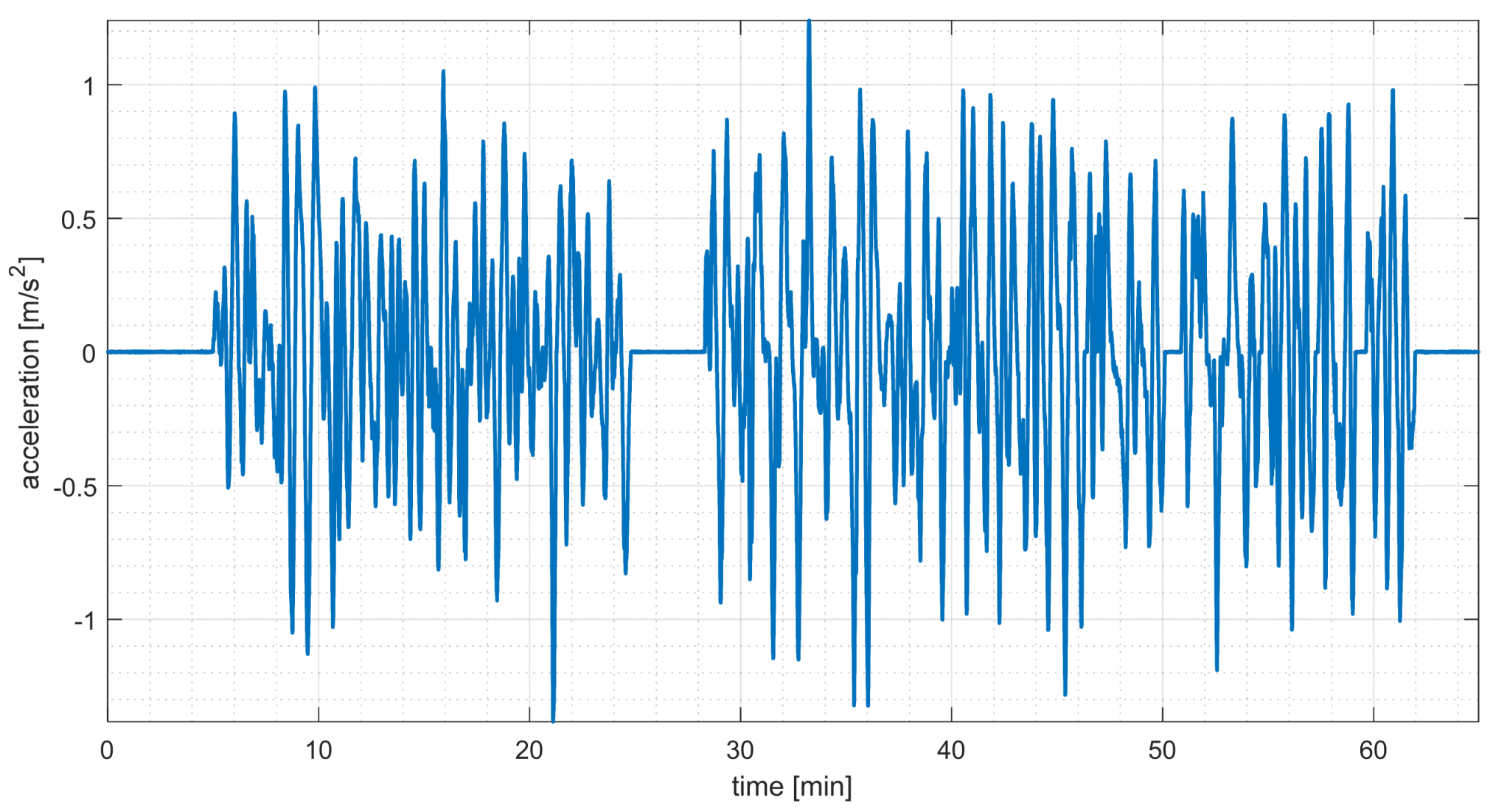
3.1. Path Characteristics
3.2. Vehicle Definition
4. Simulation Results
5. Conclusions
Author Contributions
Funding
Institutional Review Board Statement
Informed Consent Statement
Data Availability Statement
Conflicts of Interest
References
- European Commission. The European Green Deal, COM(2019) 640 Final; European Commission: Brussels, Belgium, 2019. [Google Scholar]
- European Council. European Council Meeting-Conclusions, 11 December 2020; EUCO 22/20; European Council: Brussels, Belgium, 2020. [Google Scholar]
- Omar, N.; Daowd, M.; Hegazy, O.; Mulder, G.; Timmermans, J.M.; Coosemans, T.; Van den Bossche, P.; Van Mierlo, J. Standardization work for BEV and HEV applications: Critical appraisal of recent traction battery documents. Energies 2012, 5, 138–156. [Google Scholar] [CrossRef]
- Emadi, A.; Rajashekara, K.; Williamson, S.S.; Lukic, S.M. Topological overview of hybrid electric and fuel cell vehicular power system architectures and configurations. IEEE Trans. Veh. Technol. 2005, 54, 763–770. [Google Scholar] [CrossRef]
- Ehsani, M.; Gao, Y.; Longo, S.; Ebrahimi, K. Modern Electric, Hybrid Electric, and Fuel Cell Vehicles; CRC Press: Boca Raton, FL, USA, 2018. [Google Scholar]
- Lukic, S.M.; Cao, J.; Bansal, R.C.; Rodriguez, F.; Emadi, A. Energy storage systems for automotive applications. IEEE Trans. Ind. Electron. 2008, 55, 2258–2267. [Google Scholar] [CrossRef]
- Nadeem, F.; Hussain, S.M.S.; Tiwari, P.K.; Goswami, A.K.; Ustun, T.S. Comparative review of energy storage systems, their roles, and impacts on future power systems. IEEE Access 2019, 7, 4555–4585. [Google Scholar] [CrossRef]
- Ren, G.; Ma, G.; Cong, N. Review of electrical energy storage system for vehicular applications. Renew. Sustain. Energy Rev. 2015, 41, 225–236. [Google Scholar] [CrossRef]
- Dincerab, I.; Acar, C. Review and evaluation of hydrogen production methods for better sustainability. Int. J. Hydrog. Energy 2015, 40, 11094–11111. [Google Scholar] [CrossRef]
- Noussan, M.; Raimondi, P.P.; Scita, R.; Hafner, M. The Role of Green and Blue Hydrogen in the Energy Transition—A Technological and Geopolitical Perspective. Sustainability 2020, 13, 298. [Google Scholar] [CrossRef]
- Liu, Y.; He, J.; Lu, W.; Yan, X.; Cheng, C. Evaluation Method to Select Pure Electric Buses Based on Road Operation Tests. World Electr. Veh. J. 2020, 11, 4. [Google Scholar] [CrossRef] [Green Version]
- Bergher, R. Fuel Cell Electric Buses—Potential for Sustainable Public Transport in Europe; Fuel Cells and Hydrogen Joint Undertaking: Brussels, Belgium, 2015; pp. 1–74. [Google Scholar]
- Loría, L.E.; Watson, V.; Kiso, T. Investigating users’ preferences for Low Emission Buses: Experiences from Europe’s largest hydrogen bus fleet. J. Choice Model. Open Access 2019, 32, 100169. [Google Scholar] [CrossRef]
- Hearn, C.S.; Flynn, M.M.; Lewis, M.C.; Thompson, R.C.; Murphy, B.T.; Longoria, R.G. Low-cost flywheel energy storage for a fuel cell powered transit bus. In Proceedings of the 2007 IEEE Vehicle Power and Propulsion Conference, Arlington, TX, USA, 9–12 September 2007; pp. 829–836. [Google Scholar]
- Hedlund, M.; Lundin, J.; De Santiago, J.; Abrahamsson, J.; Bernhoff, H. Flywheel Energy Storage for Automotive Applications. Energies 2015, 8, 10636–10663. [Google Scholar] [CrossRef] [Green Version]
- Doucette, R.T.; McCulloch, M. A comparison of high speed flywheels, batteries, and ultracapacitors on the bases of cost and fuel economy as energy storage system in a fuel cell based hybrid electric vehicle. J. Power Sources 2011, 196, 1163–1170. [Google Scholar] [CrossRef]
- European Commission. Critical Materials for Strategic Technologies and Sectors in the EU—A Foresight Study; European Commission: Brussels, Belgium, 2020. [Google Scholar]
- Sun, X.; Li, Z.; Wang, X.; Li, C. Technology Development of Electric Vehicles: A Review. Energies 2020, 13, 90. [Google Scholar] [CrossRef] [Green Version]
- Credo, A.; Tursini, M.; Villani, M.; Di Lodovico, C.; Orlando, M.; Frattari, F. Axial Flux PM In-Wheel Motor for Electric Vehicles: 3D Multiphysics Analysis. Energies 2021, 14, 2107. [Google Scholar] [CrossRef]
- Hernandez, M.; Messagie, M.; Hegazy, O.; Marengo, L.; Winter, O.; Van Mierlo, J. Environmental impact of traction electric motors for electric vehicles applications. Int. J. Life Cycle Assess 2017, 22, 54–65. [Google Scholar] [CrossRef]
- Boldea, I.; Tutelea, L.; Parsa, L.; Dorrell, D. Automotive Electric Propulsion Systems with Reduced or No Permanent Magnets: An Overview. IEEE Trans. Ind. Electron. 2014, 61, 5696–5711. [Google Scholar] [CrossRef]
- Widmer, J.D.; Martin, R.; Kimiabeigi, M. Electric vehicle traction motors without rare earth magnets. Sustain. Mater. Technol. 2015, 3, 7–13. [Google Scholar] [CrossRef] [Green Version]
- Heidari, H.; Rassõlkin, A.; Kallaste, A.; Vaimann, T.; Andriushchenko, E.; Belahcen, A.; Lukichev, D.V. A Review of Synchronous Reluctance Motor-Drive Advancements. Sustainability 2021, 13, 729. [Google Scholar] [CrossRef]
- Credo, A.; Fabri, G.; Villani, M.; Popescu, M. Adopting the Topology Optimization in the Design of High-Speed Synchronous Reluctance Motors for Electric Vehicles. IEEE Trans. Ind. Appl. 2020, 56, 5429–5438. [Google Scholar] [CrossRef]
- Ibrahim, M.; Sergeant, P.; Rashad, E. Simple Design Approach for Low Torque Ripple and High Output Torque Synchronous Reluctance Motors. Energies 2016, 9, 942. [Google Scholar] [CrossRef] [Green Version]
- di Leonardo, L.; Popescu, M.; Fabri, G.; Tursini, M. Performance Evaluation of an Induction Motor Drive for Traction Application. In Proceedings of the IECON 2019-45th Annual Conference of the IEEE Industrial Electronics Society, Lisbon, Portugal, 14–17 October 2019; pp. 4360–4365. [Google Scholar]
- Popescu, M.; Riviere, N.; Volpe, G.; Villani, M.; Fabri, G.; di Leonardo, L. A Copper Rotor Induction Motor Solution for Electrical Vehicles Traction System. In Proceedings of the 2019 IEEE Energy Conversion Congress and Exposition (ECCE), Baltimore, MD, USA, 29 September–3 October 2019; pp. 3924–3930. [Google Scholar]
- D’Ovidio, G.; Masciovecchio, C.; Rotondale, N. City Bus Powered by Hydrogen Fuel Cell and Flywheel Energy Storage System. In Proceedings of the Electric Vehicle Conference (IEVC), Florence, Italy, 17–19 December 2014; pp. 1–5. [Google Scholar]
- Li, J.; Zhao, J.; Zhang, X. A Novel Energy Recovery System Integrating Flywheel and Flow Regeneration for a Hydraulic Excavator Boom System. Energies 2020, 13, 315. [Google Scholar] [CrossRef] [Green Version]
- Canova, A.; Campanelli, F.; Quercio, M. Flywheel Energy Storage System in Italian Regional Transport Railways: A Case Study. Energies 2022, 15, 1096. [Google Scholar] [CrossRef]
- D’Ovidio, G.; Masciovecchio, C.; Rotondale, A. Hydrogen fuel cell and kinetic energy recover system technologies for powering urban bus with zero-emission energy cicle. IET Intell. Transp. Syst. 2016, 10, 573–578. [Google Scholar] [CrossRef]
- Ciancetta, F.; Ometto, A.; Rotondale, A.; Rotondale, N.; D’Ovidio, G.; Masciovecchio, C. Analysis of flywheel-fuel cell system for mini electrical bus during an urban route. In Proceedings of the SPEEDAM, Anacapri, Italy, 22–24 June 2016; pp. 1093–1098. [Google Scholar]
- Ciancetta, F.; Ometto, A.; D’Ovidio, G.; Masciovecchio, C. Modeling, Analysis and Implementation of an Urban Electric Light-Rail Train Hydrogen Powered. Int. Rev. Electr. Eng. 2019, 14, 237–245. [Google Scholar] [CrossRef]
- D’Ovidio, G.; Ometto, A.; Villante, C. A novel optimal power control for a city transit hybrid bus equipped with a partitioned hydrogen fuel cell stack. Energy J. 2020, 13, 2682. [Google Scholar] [CrossRef]
- D’Ovidio, G.; Masciovecchio, C.; Ometto, A.; Villante, C. On design of Hybrid Power Unit with Partitioned Fuel-cell and Flywheel Energy Storage System for City Transit Buses. In Proceedings of the 2020 International Symposium on Power Electronics, Electrical Drives, Automation and Motion (SPEEDAM 2020), Sorrento, Italy, 24–26 June 2020. [Google Scholar]
- Davis, W.J. The tractive resistance of electric locomotives and cars. Gen. Electr. Rev. 1926, 29, 685–707. [Google Scholar]


| Parameter | Unit | Value |
|---|---|---|
| Total cycle length | km | 26 |
| Total cycle time | s | 3300 |
| Maximum grade | % | −4.8; +6.8 |
| Maximum acceleration | m/s2 | +1.21; −1.40 |
| Average speed | km/h | 28.36 |
| Maximum speed | km/h | 64 |
| Parameter | Symbol | Unit | Value |
|---|---|---|---|
| Length | mm | 7168 | |
| Width | mm | 2052 | |
| Height | mm | 2900 | |
| Passengers sits | 20 | ||
| Full load vehicle mass | m | kg | 5600 |
| Time from 0 to 100 km/h | ta | s | 15 |
| Frontal section | m2 | 5.5 | |
| Aerodynamic coefficient | cx | 0.316 | |
| Tires | 195/75 R 16 110 R |
| Auxiliary | Power | Duty Cycle |
|---|---|---|
| Power steering | 2 kW | 7 s @ 70% |
| 14 s @ 30% | ||
| Air conditioning | 10 kW | 21 s @ 100% |
| 21 s @ 20% | ||
| Alternator | 2.5 kW | 10 s @ 30% |
| 10 s @ 50% | ||
| 20 s @ 80% |
| Parameter | Unit | Value |
|---|---|---|
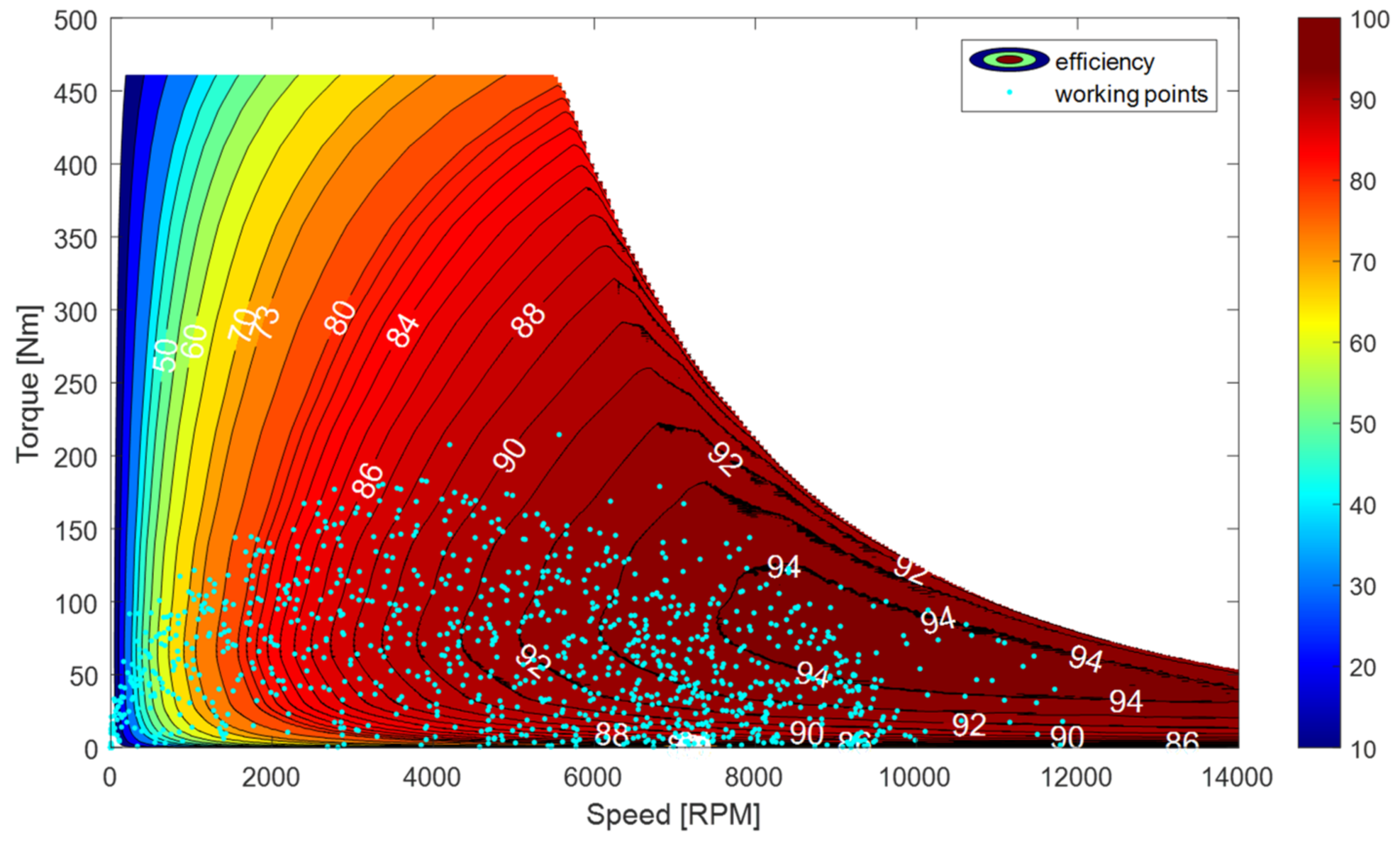
| Motor type | RE Free Synchronous Reluctance motor | |
| Motor speed | rpm | 14,000 |
| Drive type | m | SiC Mosfet based three-phase inverter |
| Drivetrain peak power | m | 200 kW |
| Drivetrain continuous power | m | 70 kW |
| Electrical drive peak efficiency | % | 94 |
| Transmission ratio | 25 | |
| Transmission efficiency (average) | % | 93 |
| FC power (at max efficiency) | kW | 10 |
| FC max efficiency | % | 55 |
| Number of FC in the stack | 5 | |
| FESS max speed | rpm | 40,000 |
| FESS bench power | kW | 200 |
| FESS bench energy | kWh | 1.5 |
| Number of FESS in the bench | 4 | |
| FESS electrical drive peak efficiency | % | 94 |
Publisher’s Note: MDPI stays neutral with regard to jurisdictional claims in published maps and institutional affiliations. |
© 2022 by the authors. Licensee MDPI, Basel, Switzerland. This article is an open access article distributed under the terms and conditions of the Creative Commons Attribution (CC BY) license (https://creativecommons.org/licenses/by/4.0/).
Share and Cite
Fabri, G.; Ometto, A.; Villani, M.; D’Ovidio, G. A Battery-Free Sustainable Powertrain Solution for Hydrogen Fuel Cell City Transit Bus Application. Sustainability 2022, 14, 5401. https://doi.org/10.3390/su14095401
Fabri G, Ometto A, Villani M, D’Ovidio G. A Battery-Free Sustainable Powertrain Solution for Hydrogen Fuel Cell City Transit Bus Application. Sustainability. 2022; 14(9):5401. https://doi.org/10.3390/su14095401
Chicago/Turabian StyleFabri, Giuseppe, Antonio Ometto, Marco Villani, and Gino D’Ovidio. 2022. "A Battery-Free Sustainable Powertrain Solution for Hydrogen Fuel Cell City Transit Bus Application" Sustainability 14, no. 9: 5401. https://doi.org/10.3390/su14095401
APA StyleFabri, G., Ometto, A., Villani, M., & D’Ovidio, G. (2022). A Battery-Free Sustainable Powertrain Solution for Hydrogen Fuel Cell City Transit Bus Application. Sustainability, 14(9), 5401. https://doi.org/10.3390/su14095401