Article

Evaluation of Water Level in Flowing Channels Using Ultrasonic Sensors

by
Tatiane Souza Rodrigues Pereira
1,
Thiago Pires de Carvalho
1,
Thiago Augusto Mendes
2,* and
Klebber Teodomiro Martins Formiga
3
1
Post-Graduate Student of the Environmental Sciences Program (PPGCIAMB)—UFG, Goiânia 74605-220, Brazil
2
Federal Institute of Education, Science, and Technology of Goias—IFG, Aparecida de Goiânia 74968-755, Brazil
3
School of Civil and Environmental Engineering (EECA)—UFG, Goiânia 74605-220, Brazil
*
Author to whom correspondence should be addressed.
Sustainability 2022, 14(9), 5512; https://doi.org/10.3390/su14095512
Submission received: 28 March 2022 / Revised: 21 April 2022 / Accepted: 27 April 2022 / Published: 4 May 2022

Abstract

:
Monitoring flow in channels is difficult, expensive, and potentially dangerous; hence, alternatives minimizing these factors are sought and indirect methods to measure the flow based on water-level information, among others, are employed. Ultrasonic sensors along with Arduino are widely used to monitor levels in reservoirs; however, the accuracy of this method in turbulent flow regimes has not been evaluated. Therefore, in this study, we evaluated the level of open channel flows using a combination of Arduino and ultrasonic sensors whilst considering turbulence. Additionally, we statistically compared the simultaneous measurements of levels obtained using five ultrasonic sensors with those of five rulers filmed individually along an artificial channel, for four permanent and two transient regimes. The results showed that the errors in measurements increased with increasing turbulence. These errors were within the range of hydraulic measurements (<0.020 m), indicating that the procedure is valid for experienced conditions. Therefore, the combination of Arduino and ultrasonic sensors is a technically and economically viable alternative. However, calibrating and validating the sensors for distances greater than 0.400 m should be performed with care because the bench tests performed in static conditions were limitedly accurate in measuring distances greater than 0.200 m.

1. Introduction

The monitoring of channel flow is essential for the study of water resources, where several measurement techniques can be used [1]. In general, a series of factors linked to the flow, such as the depth and velocity of the flow, and the turbulence, need to be evaluated in advance because some of them are used to define which technique is more suitable for a particular measurement problem [2].
The most commonly used water monitoring systems measure the water level using pressure transducers (linigraphs) or vertical linimetric rulers and are used in manual measurements [3]. All these methods have a similar objective of providing indirect measurements for the calculation of the flow series, because the flow is a difficult variable to measure directly, and even more difficult to monitor continuously [4,5]; however, it is the most common fluvial hydraulic measurement, being the main parameter to characterize the dynamics of a river [6]. To make the level data compatible with the flow, it is necessary to carry out measurements of flows and levels from the study section, in order to have the rating curve in the study section. An alternative for the continuous monitoring of levels and velocities is the use of techniques based on Particle Image Velocimetry (PIV) [7] because they allow the direct evaluation of the two variables for the flow, level, and velocity at the surface. Typically, each of these methods has advantages and limitations regarding the costs, facilities, efficiency, accuracy, autonomy, specialized human resources, data collection and transmission, measurement conversion, etc.
With the need to increasingly improve the monitoring of flow rates at different points, it is necessary to implement alternative methods that are, simultaneously, efficient and have a low cost of acquisition, installation, and maintenance. For these methods, the association of the Arduino controller and ultrasonic distance sensor has been used in level measurement [8]. Arduino is the most flexible and low-cost electronic prototyping platform in existence, besides being compatible with a range of sensors developed for different purposes [9]. Thus, according to Kondaveeti et al. [10], different Arduino boards can be prototyped to develop solutions for different problems in various fields of knowledge (health, agriculture, automation, education, mining, energy, defense etc.).
The association of Arduino and ultrasonic sensors, especially the HC-SR04 sensor model, is used to monitor water levels in reservoirs [11,12,13,14,15,16,17,18,19,20], where the water surface is smoother due to the lack of turbulence. Thus, because the surface is always regular, the measurement tends to be more accurate and stable. The opposite tends to occur in channels, where the water line is irregular due to turbulence, which can alter the angle of wave reflection and, consequently, change the accuracy of the measurement in the form of dispersion around the real value.
Thus, when Arduino and ultrasonic sensors are applied to static surfaces, the results show a better efficiency and stronger correlations between the ultrasonic sensor measurements and the observations, whether by ruler or linigraph [21,22,23]; constituting a high-value water level monitoring method when the low cost is added [18,20].
The use of Arduino and ultrasonic sensors to monitor water levels in free-surface flow has been insufficiently investigated. The limitations in the applications are related to the ignorance of the random errors generated in the measurements due to the turbulence of the flow, which can vary between sensors of the same model or different models, since the sensors are not factory calibrated.
According to Bae and Ji [24], measurements for free flow in channels tend to exhibit a relatively large number of discrepant values for non-permanent flows and Panagopoulos et al. [25] found strong correlations of the measurement of levels between ultrasonic sensors and linigraphs; however, 7% higher for the ultrasonic sensors.
Thus, this study aims to evaluate water level monitoring data through the association of the Arduino controller and five HC-SR04 ultrasonic sensors, for the investigation of the flows in artificial channels considering the effects of turbulence (irregular water surface and variable runoff). In artificial channels, there are always great difficulties in determining flows, especially in unsteady flows, so the best determination of the variation of flow levels fills this difficulty, since it can relate level and flow.

2. Materials and Methods

2.1. Hardware Components Description—Ultrasonic Sensor and Arduino

The components of our proposed circuit are HC-SR04 ultrasonic sensors (Figure 1a), which is a standard and affordable model and an Arduino with an embedded microcontroller board based on ATmega2560 (Figure 1b).
The ultrasonic sensor measures distances between 0.20 m and 4.00 m with an accuracy of 0.003 m, opening angle of 30°, and ultrasonic frequency of 40 kHz [26,27]. In practice, an ultrasonic sensor is composed of an emitter (trigger) and a receiver (echo), where the emitter emits a high-frequency ultrasonic sound wave that reflects on any surface (in this case water); subsequently, the receiver partially receives the sound wave as an echo. The control circuits then process this echo to measure the time and calculate the difference between the sender and receiver signal. Subsequently, the echo wave’s signal duration or return time is converted into the distance [23]. Thus, the ultrasonic sensor’s calculation of the distance (D) in centimeters is given by the following Equation:
D = V t 2
where V is the speed of sound in air of 340 m s−1 (0.034 cm μs −1) and t (μs) is the sending-response time of the acoustic pulse. Their product is divided by two because the wave travels the measured distance twice, once on the way (trigger) to the obstacle and once back after reflection (echo). The echo pulse can vary from a minimum of 150 μs to a maximum of 25 ms. If there is no obstacle in the path of the emitted wave (or the wave gets lost on the path for some reason), the obtained time value will be 38 ms, the maximum specified by the manufacturer [28].
Arduino is an open-source platform for electronic prototyping based on hardware (controller board) and software (development environment) flexibility. The Arduino used in this study was the MEGA type with 54 digital input and output pins, 16 analog inputs, 4 serial communication ports, reset button, USB communication, and an external power connector (Figure 1b) [27].

2.2. Bench Tests

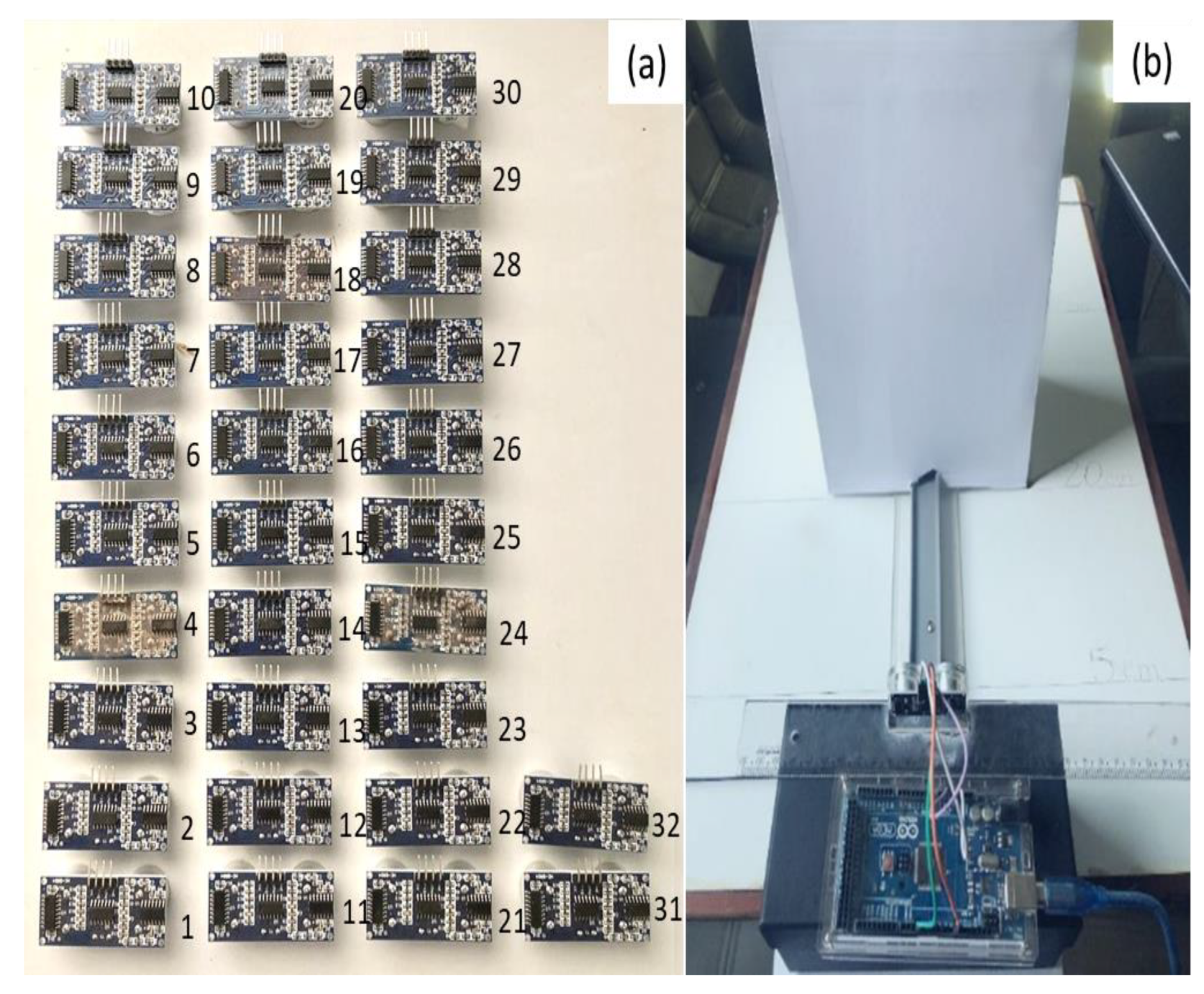
The bench tests were performed to validate the measurements obtained by the ultrasonic sensors against the readings of a fixed measurement scale and thus, determine the errors between them because the sensors from the manufacturer need to be individually calibrated. We used an XY table from a board with a parallel ruler and fixed the distances of 0.050, 0.200, and 0.400 m for calibration (Figure 2).
After analysis, we selected only those ultrasonic sensors from a set of 32, named S1 to S32, that presented the best results (lowest error values) in the bench test.

2.3. Experimental Set-Up and Monitoring of Flow Events in the Channel

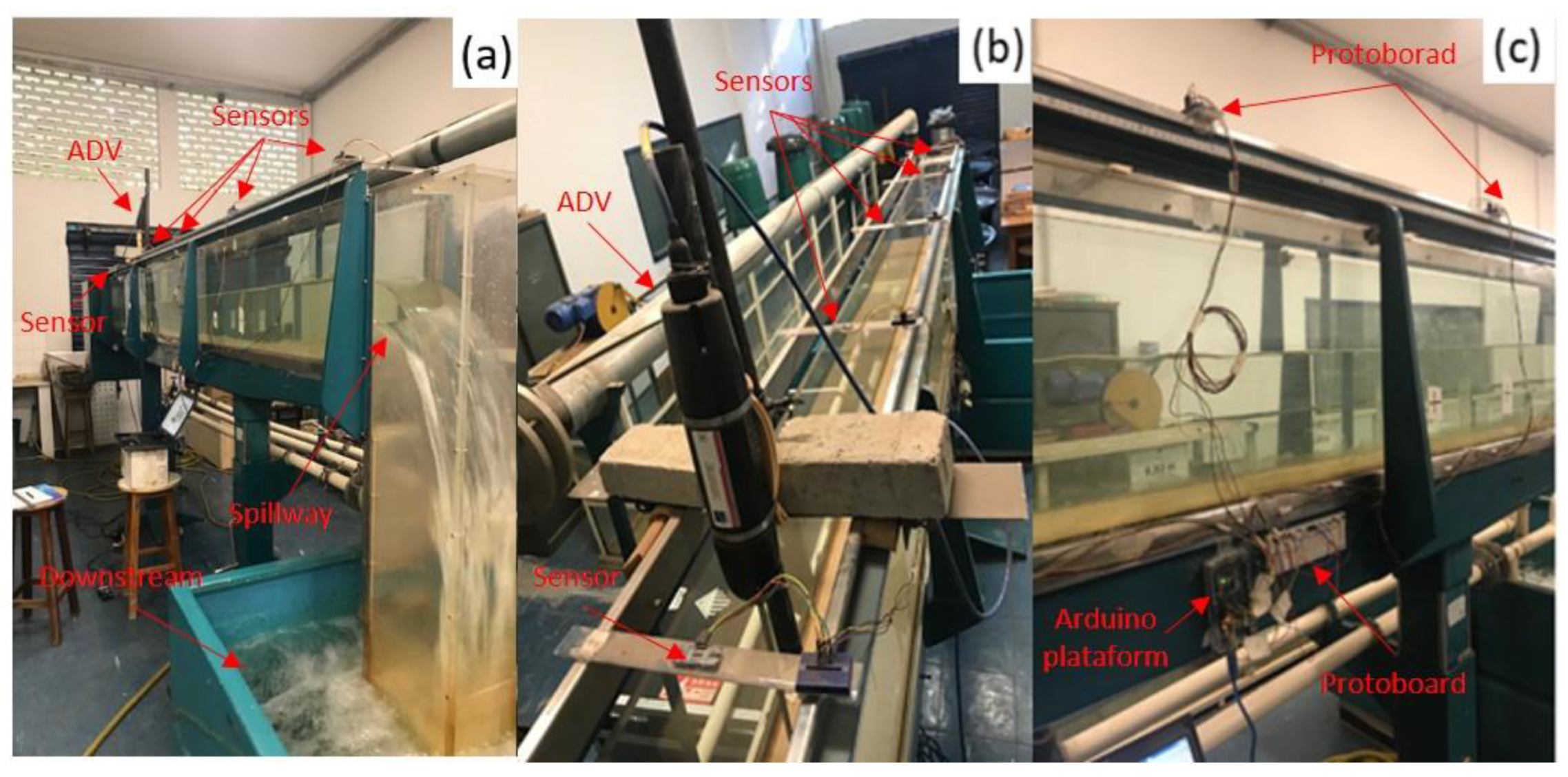
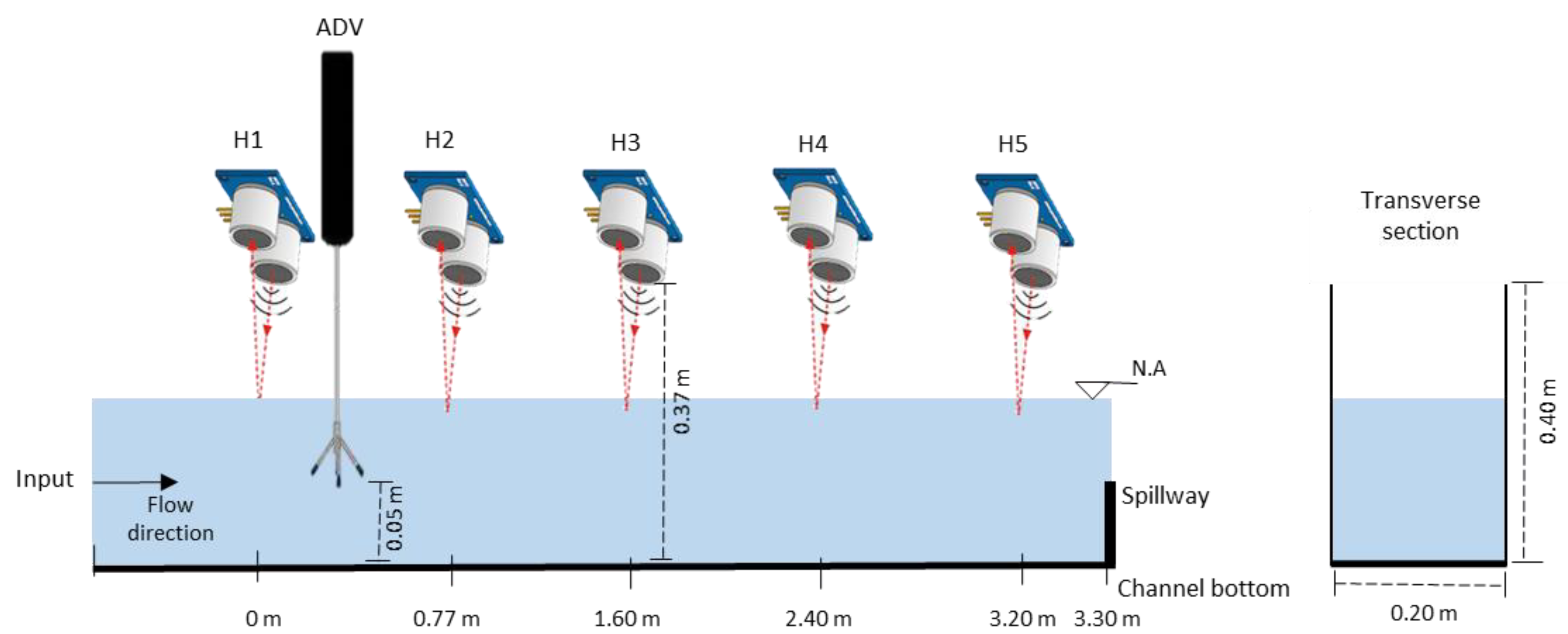
The scheme used to measure the water levels had five ultrasonic sensors installed at different points of the upper part of the experimental channel (Figure 3). The channel had 4.00 m of length, a rectangular cross-section of 0.205 × 0.400 m, lateral walls of transparent glass, and a transparent acrylic bottom. A slender sill spillway without lateral contractions was set up at the end of the channel at a height of 0.10 m and the slope of the channel bottom was set at 0.017 (1.7%) for permanent flows (Events 1 to 4). For transient flows, the slope was set at 0.0055 (Event 5) and 0.008 (Event 6). These values were chosen to represent the types of flows (permanent and transient) in the channel, as well as to compare the turbulence behavior. Only 3.30 m of the total channel length was analyzed to exclude the strongest turbulences generated at the channel inlet.
The electronic scheme presented in Figure 4 was used to connect the ultrasonic sensors to the Arduino: two power pins (Voltage Current Continuous—VCC = 5 V in red color and Ground Neutral Difference—GND in blue color) and ten digital ports (five pins for trigger and five pins for echo). The software (script) was developed using the Ultrasonic library (Appendix A—Algorithm A1). The Arduino was programmed to record the average of ten water-level readings per second in millimeters for each sensor presented in the serial monitor and export the data to a file (.txt), according to Algorithm A1 (Appendix A).
As shown in Figure 5, the positioning of the ultrasonic sensors along the hydraulic channel was aimed at acquiring the water-level data from different sections of interest. The water-level measurements were performed using a reading algorithm and the output data transferred to the Arduino (Equation (2)) to continuously and simultaneously obtain the average water levels from the five sensors in time increments of approximately 0.6 s.
N A ( p ) x = d t ( p ) d ( y , p )
where NA(p)x is the height of water level recorded for point p in section x (m), dt(p) is the total distance between the ultrasonic sensor and channel bottom for point p (m), d(y,p) is the distance variation or the distance recorded between the ultrasonic sensor and water level y for point p (m), p is the installation point of each ultrasonic sensor, and y is the distance recorded between sensor and water level (m).
Additionally, the rulers at each point were filmed simultaneously at the times when measurements of the ultrasonic sensors were taken. The average flow velocity was measured with an ADV to further evaluate the accuracy of the measurements in different flow conditions. All simulated flows were considered turbulent because the Reynolds numbers for the different events were greater than 2000 [29], ranging from 9792 to 32,914 for the permanent flows and were 22,186 and 23,487 for the transient flows. Moreover, deviations and noise were verified in the readings of the sensors, which increased as the flow became more turbulent. A Kalman filter [30] was applied to clean the data and circumvent this problem.
The in-channel height measurements were evaluated using the quantitative statistics recommended by [31], including one absolute error statistic, root mean square error (RMSE), using the standard deviation of the measured data to quantify the deviation in the units of the dataset (Equation (3)) and a graphical technique, called linigram, to provide a visual comparison of measured constituent data. Additionally, we evaluated percent bias (PBIAS) to assess the average tendency of the sensor data to be larger or smaller than the corresponding ruler measurements and percent relative error (RE), as per Equations (4) and (5), respectively. Lin’s Concordance Correlation Coefficient (LCCC) [32] was also used to assess the degree of agreement between measures (Equation (6)):
R M S E = i = 1 t H r u l e r i , x H s e n s o r i , x 2 i = 1 t H r u l e r i , x
P B I A S = i = 1 t H r u l e r i , x H s e n s o r i , x i = 1 t H r u l e r i , x .100
R E = i = 1 t H r u l e r i , x H s e n s o r i , x i = 1 t H r u l e r i , x .100
L C C C = 2 r S H r u l e r S H s e n s o r H r u l e r ¯ H s e n s o r ¯ 2 + S H r u l e r 2 + S H s e n s o r 2
where Hruleri,x is the height of water observed on the ruler at a time i in section x (m), Hsensori,x is the height of water measured by the sensor at time i in section x (m), t is the number of time intervals, r is Pearson’s correlation coefficient and S is the variance in the Hruler and Hsensor populations.

3. Results

3.1. Bench Test

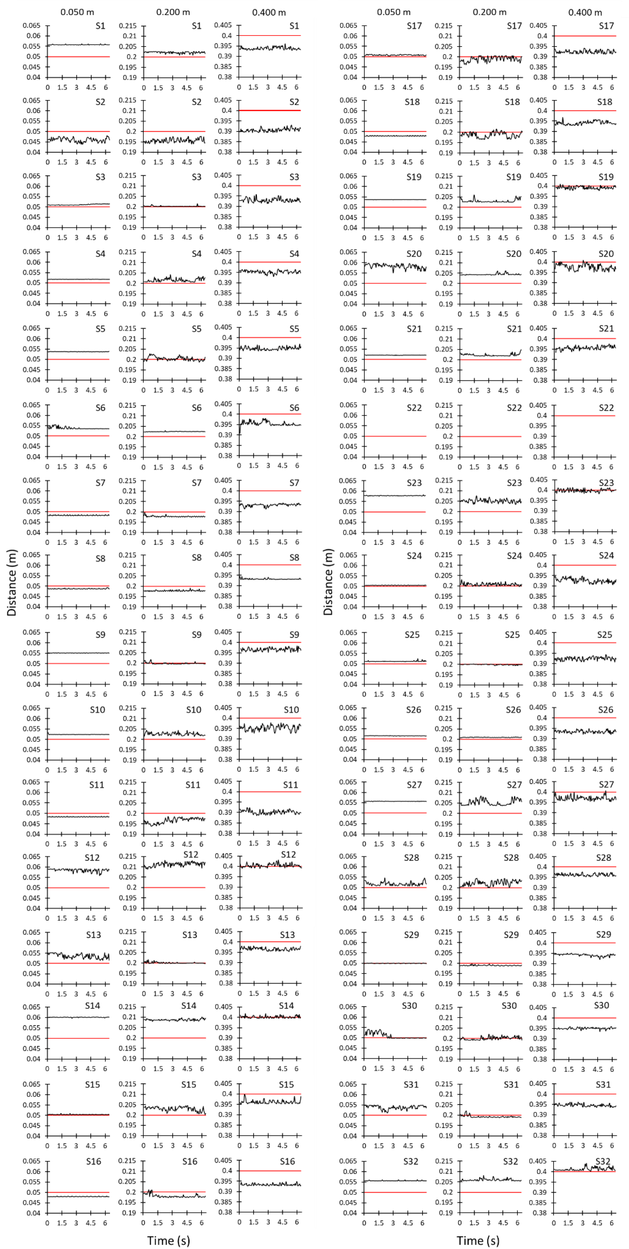
We evaluated 32 sensors, named S1 to S32 (Figure 2) and we selected five of the sensors that have the lowest standard deviation in readings within the precision defined by the manufacturer in the study, because the limited length of the channel did not allow for the placement of more sensors; the angle of reading of each sensor would have overlapped causing interference in the readings. This is because the opening angle of the sensor forms a cone of scattering waves in the direction of the measurement, thus reaching the surface to be measured; by the law of reflection, every point on the surface of the obstacle on which an ultrasonic wave falls becomes a new focus, further propagating toward the transducer [28]. This indicates that for the channel in question, the water depths should always be higher than 0.027 m ( t g   75 ° × 0.10   m ) to avoid interference from the channel walls on the readings. The readings obtained from the five sensors in the measurement cycles are specified in Figure 6, the individual readings of each sensor are specified in Figure A1 (Appendix B), and the errors and standard deviations are shown in Table 1.
Additionally, 23 sensors from the total showed tolerable errors in the range of ± 0.003 m specified by the manufacturer for the distance of up to 0.200 m and none for the distance of 0.400 m. However, the number of approved sensors for the distance of up to 0.200 m rose to 30 for the error relaxed to ± 0.005 m, and for the distance of 0.400 m, only two sensors were approvable. This indicated that the errors (uncertainties) increased as the distance increased. Thus, only the sensors S3, S4, S7, S15, and S17 were deemed appropriate for the study’s objectives, as they presented the lowest deviations in readings, and it was possible to quantify the uncertainty associated with each of them.
Graphically, it is possible to verify that the readings have minor deviations the closer the sensors are to the obstacle and tend to increase when the distance is greater (Figure 6). This pattern is also perceived when analyzing the standard deviations of the samples in Table 1 because they indicate a greater dispersion in the readings as the distance between the sensors and the obstacle increases, which for the distance of 0.050 m is between zero and 0.0002, for 0.200 m between 0.0002 and 0.0013, and for 0.400 m between 0.0006 and 0.0090.
Quantitatively, for the measured distances between 0.200 and 0.050 m, the admissible errors are well in the range of ±0.003 m established by the manufacturer, which can be seen in Table 1, where the absolute differences range from −0.002 to 0.003 m. However, for the distance of 0.400 m, the errors were slightly higher, but within the error range of ± 0.005 m for sensors S4 and S15. This was a relaxed range beyond that provided by the manufacturer due to conditions that might have contributed to increased uncertainty in the measurement, such as unevenness in the XY table, displacement of the axis of the ultrasonic sensor with respect to the target, unevenness, or displacement in the z-axis of the target, high brightness, and temperature [26]; however, these uncertainties are not addressed individually in the study. It is noteworthy that for this study, that is, during the laboratory tests in the artificial channel, the temperature and light conditions were adjusted as recommended [26] so that they did not interfere with the measurements of the ultrasonic sensors.
In addition, the absolute differences of the distances compared to the average distances are evidently underestimated for 0.400 m and show a difference of −0.008 m for sensor S17 and −0.007 m for sensors S3 and S7. The results obtained in this study were close to those found by [33], which verified the limitation in estimating the distances above 0.30 m with high accuracy for the same model of ultrasonic sensor.
The ultrasonic sensors in the channel were designated H1 to H5, according to the scheme presented previously (Figure 5). Thus, the bench tests to evaluate the ultrasonic sensors were verifiably an essential step before their application for discarding the defective sensors or those that presented significant errors in readings.

3.2. Evaluation of the Monitored Events

The measurement deviations between the water levels measured with the ultrasonic sensors and with the rulers for the six events, EV1 to EV6, were evaluated. As the ultrasonic sensors showed better results in the bench test for distances up to 0.200 m, the flow simulations were within this range to work with lower degrees of uncertainty. Additionally, the flow rates varied from 5 to 20 L s−1 and the spillway was positioned at a height of 0.100 m.
The results are outstanding considering that the measurements were performed in a fluid medium in motion because the measurements with the rulers and sensors show a high degree of agreement (Figure 7 and Table 2), with LCCC values for the permanent EV1 to EV4 of 0.869, 0.845, 0.819 and 0.790 and for the transient EV5 and EV6 the means of 0.984 and 0.994. In the latter case, it is appropriate to evaluate the agreement by sensor (H1 to H5) versus ruler (gold standard) individually and not the event as a whole, as there is displacement of the flood wave in time. Thus, for EV5 the LCCC for the measurement points ranged from 0.973 to 0.995 and for EV6 ranged from 0.992 to 0.996. In general, LCCC close to 1 indicate strong agreement between the variables [32], LCCC ≥ 0.80 can be considered excellent [34] and LCCC > 0.99 indicate near perfect agreement [35]. Thus, for the measurements of permanent events, which have values with little variation in the measurement, the value was lower than the transient events, which by presenting changes, show that there was an excellent adjustment in agreement between the sensor data and the level measured in the ruler.
The mean ( X ¯ ) of the water levels measured with the rulers was slightly higher than those measured by the ultrasonic sensors in most of the measurement time (Table 2), indicating that the measurements with ultrasonic sensors were underestimates, which can be observed in Figure 7. The standard deviations (S) of the rulers were considerably lower than for the ultrasonic sensors, indicating that the measurements with rulers showed lower uncertainties because the dispersion of the measurements around the averages was smaller, which made them more reliable. Additionally, this was because the ultrasonic sensors used surface reflectance, which is irregular, and some pulses had different patterns. It was also observed that S decreased as the Reynolds number increased because of the decreased turbulence. As the ultrasonic sensors were not developed to measure fluid levels, their measurements had a more significant error than for measuring the distances to solid surfaces because water has an irregular and variable surface that increases the errors in the measurements. Considering all these factors, the measurements with the ultrasonic sensors showed good agreement compared to the rulers’ measurements.
Analysis of the events according to the characteristics of the flow, showed that for permanent events (EV1 to EV4), in which the turbulence was lower, S was between 0.0 and 0.00240 m for the rulers and between 0.00032 and 0.00311 m for the ultrasonic sensors. For the transient events (EV5 and EV6), where there is more variability in flow rates, S was high and ranged from 0.02055 to 0.0252525 m for the rulers and from 0.02048 to 0.02537 m for the ultrasonic sensors. These results indicated that the dispersion of the measurements, for the averages of the different characteristics of flow considered, was more linked to the characteristics of the flow themselves than to the measurement methods because the differences between the S of the rulers and sensors were minimal for the same flow conditions. As shown in Figure 7, the most significant deviations are practically minor and there is a significant difference of S only with change from one regime to another. Thus, the more turbulent the flow, the greater are the uncertainties in the measurements.
Similar behaviors were verified analyzing other quantitative statistical elements in the events, verifying that for the average RMSE, the errors increased as the flow rate (Q) became larger, as for EV1 with Q = 5.0 L s−1, the error was 0.00429 m; for EV2 with Q = 10.0 L s−1, the error was 0.00489 m; for EV3 with Q = 15.0 L s−1, the error was 0.00632 m; and for EV4 with Q = 20.0 L s−1, the error was 0.00662 m. For the transient events, EV5 and EV6 with Q from 5.0 to 20.0 L s−1, the average RMSE were 0.00364 and 0.00241 m, respectively. Thus, the transient events did not show a greater error than those in the permanent regime, indicating that for the average RMSE, the type of event has no significant interference.
Additionally, we verified that for both the S and average RMSE per event, the standard uncertainty estimates of 0.02 m for varying operational conditions (measurement environment and instrument operations) of flow measurement [36,37], were considerably lower for the permanent flows; however, S was slightly above this value for the transient flows.
The values of the mean RMSE per ultrasonic sensor were close for H1 to H5, equaling 0.00671, 0.00396, 0.00619, 0.00606, and 0.00474 m, respectively, with no pattern relating the error to the turbulence for the analyzed conditions.
Of all the RMSE evaluations of the individual ultrasonic sensors for the permanent flow, only 15% of the average values met the accuracy metric provided by the manufacturer (± 0.003 m) in general; occurring only three times, specifically in EV1, for the low flow rate of 5 L s −1 and sensors H1, H2, and H5. In general, evaluation of the RMSE of all the events and sensors for the permanent flow verified that 45% of the errors were in the RMSE range of 0.005 to 0.006 m, 15% in the range of 0.004 to 0.007, 5% at 0.008 m and 10% at 0.009 m. For the transient events, the RMSE met the range of ± 0.003 m accuracy for EV5 and sensors H1 and H2 (0.002 and 0.003 m), but exceeded for the sensors H3, H4, and H5 (0.004, 0.005, and 0.004 m, respectively); further, met the range for EV6 for all sensors, ranging from 0.002 to 0.003 m. Thus, the sensor error was greater than that observed for the solid surface (Table 1), verifying that measuring the liquid surface increases the sensor error.
Additionally for PBIAS, there was a bias in the form of underestimation of the level measurements with the sensors compared to the measurements with the rulers, with PBIAS ranging from 0.79 to 4.86%, except for the sensor H1 during the transient flows, which showed a slight bias in the form of overestimation of the level measurements by −0.26% and −0.72% for EV5 and EV6, respectively. These results indicated that the average of the measurements of levels with sensors was lower compared to the measurements with the rulers, since the values were positive for most of the cases, confirming the analysis of the X ¯ results. The ideal value of PBIAS is zero, meaning that there is a precise agreement between the measurements; however, based on the results found, it can be classified as very good, because despite not evaluating the data from the point of view of simulation in models, in which PBIAS should be equal to ±10% for flows with low uncertainty or equal to ± 25% for flows with larger uncertainties [38]. These performance classifications provide an indication of what could be considered as very good, good, satisfactory, and unsatisfactory results for this statistic applied to flow evaluation, which in this case were less than 5% for the different types of flows analyzed.
As the criteria of PBIAS reflects the RE in principle, similar results were obtained for RE. RE was less than 5% for all events, indicating a high degree of agreement between the levels measured by the rulers and sensors. Moreover, the average RE for the permanent and transient flows was 2.93% and 1.38%, respectively. Generally, the highest RE occurred in the sensor H1, representing the region of more significant turbulence. However, the errors were similar to the other measurement points of less surface agitation, indicating that the sensor made a good measurement regardless of the level of turbulence during the experiment.
Finally, we verified that the turbulence, RMSE, and S values increased as the Reynolds number increased, indicating that the natural flow turbulence in channels increased the errors in the measurements. This was as expected, as higher flow rates caused higher velocities in the channel, and therefore, greater water agitation. Subsequently, this caused a greater dispersion of the acoustic waves because of the rapidly changing angle of reflectance, which modified the capture of the wave by the sensor. For the transient events, EV5 and EV6, we verified that EV6 was faster for the same flow range than EV5 because its slope of the channel bottom (So) was greater (0.008), which generated higher velocities of the flow by gravity and then a higher average Reynolds number as well.

4. Discussion

The results of this work suggest that the combination of Arduino and ultrasonic sensors is a technically and economically feasible way to measure water levels accurately in channels for levels smaller than 0.200 m, both for permanent and transient flows, including conditions in which the turbulence is high. This was supported by the fact that there was little change in errors for the statistical comparison of measurements between the different regimes.
Quality control of the ultrasonic sensors before their use by employing a bench test was necessary to identify defective sensors and check their errors under controlled conditions because commercially available ultrasonic sensors are usually not calibrated beforehand, addition to realizing that there is no high-quality control in its manufacture (a fact justifiable by the low cost of acquisition). Though it is commonly accepted that measured data have inherent uncertainties, these are rarely considered in evaluations [38,39]; therefore, a quality assessment of the sensors tends not to be performed in studies. Instead, a single sensor that will be applied is evaluated without considering the spare sensors that could present smaller measurement errors. Thus, our approach of an initial assessment works well for choosing ultrasonic sensors because the associated uncertainties will be low.
The bench test verified that there was an increase in the underestimation of the measured water level as the distance of the sensor from water surface increased. Distances up to 0.200 m presented good accuracy; however, for distance greater than 0.400 m, there was a tendency for a slight underestimation of 0.006 m (15%) in the depth. These results were consistent with those by [33], which verified the limitation in estimating distances above 0.300 m with a high accuracy for the same sensor model.
Some important considerations about the use and applicability of the ultrasonic sensors used in this study can be seen in water level monitoring in reservoirs [11,12,13,14,15,16,17]. To evaluate the accuracies of the measured levels during monitoring, Drage et al. [18] constructed a low-cost (between USD 150 and 225) real-time groundwater level monitoring network for domestic water wells, which has a similar characteristic to reservoirs, and compared the average absolute level errors to those of linigraphs less than 0.02 m. Sahoo and Udgata [19] developed a new low-cost neural-network-based system to increase the accuracy of the water level measurement using the HC-SR04 sensor for storage tanks at different depths. The measurement error was limited by ±1 cm for the distance measurements ranging from 2 cm to 5 m, and the model was able to extend the maximum standard operating range of the sensor from 4 to 5 m. Olisa et al. [20] developed a low-cost system using the HC-SR04 sensor for the real-time water level monitoring of two domestic tanks. In their findings, they verified that the absolute relative error was less than 10% for the majority of the monitoring times, and there were dispersions in the measurements for the suspended tank filling conditions when turbulence exists.
Thus, Bae and Ji [24] found dispersions close to 2 cm in their water level measurements for four events using two HC-SR04 ultrasonic sensors in a large-scale experimental channel and developed a data processing algorithm for removing and smoothing discrepant values based on Exponentially Weighted Moving Average (EWMA). Panagopoulos et al. [25] employed water level monitoring in an urban stream for nine months using a linigraph and a HRXL-MaxSonar-WR ultrasonic sensor, and found that both showed strong correlations with the measurements of the linigraph.
However, it should be noted that this is an introductory study that presents indicative results for a specific sensor model and is limited as such. Therefore, we suggest further research to be conducted for different sensor models and level ranges higher than 0.200 m to analyze the errors committed in the static measurements and flow in the channels.
Additionally, we observed interference in the Reynolds number, but the RE remained lower than 4.86% for all the cases. In all flows, there was a tendency for the Reynolds number to decrease as one approached the end of the channel, as the depth increased and the flow velocity decreased, except for sensor H1 (system entrance), which indicated turbulent effects from the channel entrance. In general, there was a tendency for the error to increase with the Reynolds number because when comparing the mean errors of the events, they increased along with the flow measurement, and consequently, the Reynolds number increased, indicating that the turbulence of the flow was a source of error that deserved to be considered.
The statistical (RMSE, PBIAS, RE, LCCC, Mean and Standard Deviation) and graphical techniques used appropriately evaluated the results by quantifying the error in the data units, verifying the average tendency of the data to be higher or lower than the reference data, and providing a visual comparison of the measured constituent data. For providing more data of low uncertainty as we have in this study, we suggest further research into defining performance classifications to establish a platform for the evaluation of the statistics used and for the comparison of level measurements with rulers and other different models of existing ultrasonic sensors. This will help choose sensor models in future research related to water flow measurement.
The results presented enable the use of ultrasonic sensors in laboratory environments in research in which flow levels monitoring are required, such as roughness coefficient calibration tests, monitoring of subcritical e supercritical flows (either in steady or unsteady flow). However, there is a limitation in the number of points to be monitored due to the fact that there must be spacing between the sensors so that there is no influence of the pulse of one on the other. It is still necessary to improve the filtering of data obtained from sensor readings due to variations in readings, especially in flows that present high turbulence on the free surface.
From the point of view of applicability of ultrasonic sensors in the field, the possibility of use for measuring and monitoring water depth levels in channels or reservoirs to determine flow rates in steady state and roughness stands out, with emphasis on installation and operation care of the sensors, either from the point of view of protection against the weather (rainfall, temperature, and pressure) or overlapping or operational influence of one sensor over the other.
Finally, the cost is an important variable to consider, as continuous monitoring of flows requires investment. The cost of acquiring the sensors to monitor the levels was low compared to the investments needed to acquire instruments developed exclusively for these purposes. The Arduino controller board cost USD 38.27, and each sensor cost USD 3.57. A total of 32 sensors were used, which is equivalent to USD 114.29. Six protoboards and 24 connection wires were also used, generating an extra cost of USD 106.00 (price in US dollars for the year 2020). However, it is noteworthy that in our study, a low cost was achieved for monitoring the levels at five points with the ultrasonic sensors, despite the need for five cameras to monitor the rulers and validate the data. Nevertheless, using Arduino reduced the data acquisition time and easily executed the iteration process using a coding loop Algorithm A1 (Arduino library—Appendix A).

5. Conclusions

It should be noted that the following conclusions are based on limited data sets. Therefore, they should be considered indicative rather than confirmative.
This study evaluated the water level measurements using a combination of an Arduino controller and ultrasonic sensors for flow in open channels and considering the turbulence effects. The measurements performed with the sensors were compared by simultaneously filming the rulers installed at the same measurement points. After examining the results of six flow events, four in the permanent regime and two in the transient regime, based on the statistical analysis performed, it could be concluded that the ultrasonic sensors are adequate tools to measure levels in channels with accuracy, even for conditions of high turbulence.
Although previous findings have indicated that ultrasonic sensors were suitable for measuring levels in the permanent regime in reservoirs, our study evaluated levels beyond this regime for transient flows in a channel, considering a reasonable number of events in the evaluations. The results indicated that our proposed set-up is a technically and economically viable way to monitor levels accurately in channels by providing results close to that of the rulers for different flow conditions. Therefore, our collected data of low uncertainty offers much value and can be used in the evaluation of other models.
Finally, the increase in the error with increasing turbulence due to the irregularity of the measured surface is highlighted in this paper. Additionally, this error is within the range for hydraulic measurements, which should be less than 0.020 m, indicating that our proposed procedure is valid. A future study is important for the calibration and validation of the equipment needed for measuring distances greater than 0.400 m.

Author Contributions

Conceptualization, T.S.R.P., T.P.d.C., T.A.M. and K.T.M.F.; methodology, T.S.R.P. and T.A.M.; formal analysis, T.S.R.P. and T.P.d.C.; investigation, T.S.R.P., T.P.d.C. and T.A.M.; resources, K.T.M.F.; data curation, T.S.R.P., T.P.d.C. and T.A.M.; writing—original draft preparation, T.S.R.P., T.P.d.C. and T.A.M.; writing—review and editing, T.S.R.P., T.A.M. and K.T.M.F.; supervision, T.A.M. and K.T.M.F.; project administration, K.T.M.F.; funding acquisition, K.T.M.F. All authors have read and agreed to the published version of the manuscript.

Funding

The research was funded in part by Financiadora de Estudos e Projetos (FINEP—Brazil), Agreement 01.13.0455.00, Ref. 1106/2013, Fundação de Apoio à Pesquisa–UFG (FUNAPE—Brazil), and Coordenação de Aperfeiçoamento de Pessoal de Nível Superior (CAPES—Brazil).

Institutional Review Board Statement

Not applicable.

Informed Consent Statement

Not applicable.

Data Availability Statement

Not applicable.

Acknowledgments

The authors are indebted to the following institutions that supported the research activities reported in this paper in different ways: The Federal University of Goiás (UFG), Federal Institute of Education, Science and Technology of Goiás (IFG) and Research Support Foundation (FUNAPE—UFG).

Conflicts of Interest

The authors declare that they have no known competing financial interests or personal relationships that could have appeared to influence the work reported in this paper. Thus, the authors declare no conflict of interest.

Appendix A

Algorithm A1: Script on Arduino without Kalman Filter Application.
#include <Ultrasonic.h>

#define echoPin_1 3 //pin 3 receives the echo pulse
#define trigPin_1 4 //pin 4 sends the pulse to generate the echo
#define echoPin_2 5 //pin 5 receives the echo pulse
#define trigPin_2 6 //pin 6 sends the pulse to generate the echo
#define echoPin_3 7 //pin 7 receives the echo pulse
#define trigPin_3 8 //pin 8 sends the pulse to generate the echo
#define echoPin_4 9 //pin 9 receives the echo pulse
#define trigPin_4 10 //pin 10 sends the pulse to generate the echo
#define echoPin_5 11 //pin 3 receives the echo pulse
#define trigPin_5 12 //pin 12 sends the pulse to generate the echo

int myCounter = 0; //declare your variable myCounter and set to 0
int servoControlPin = 6; //dervo control line is connected to pin 6
float pingTime_1; //time for ping to travel from sensor to target and return
float pingTime_2; //time for ping to travel from sensor to target and return
float pingTime_3; //time for ping to travel from sensor to target and return
float pingTime_4; //time for ping to travel from sensor to target and return
float pingTime_5; //time for ping to travel from sensor to target and return

float targetDistance_1; //distance to target in inches—sensor 1
float targetDistance_2; //distance to target in inches—sensor 2
float targetDistance_3; //distance to target in inches—sensor 3
float targetDistance_4; //distance to target in inches—sensor 4
float targetDistance_5; //distance to target in inches—sensor 5

float distanciaMedia_1 = 0; //average reading distance—sensor 1
float distanciaMedia_2 = 0; //average reading distance—sensor 2
float distanciaMedia_3 = 0; //average reading distance—sensor 3
float distanciaMedia_4 = 0; //average reading distance—sensor 4
float distanciaMedia_5 = 0; //average reading distance—sensor 5

float speedOfSound = 346; //speed of sound in m/s at 20 °C

int leituras = 10; //number of readings to find the average
int k = 1; //read counter

float distancia_1[11] = {0, 0, 0, 0, 0, 0, 0, 0, 0, 0, 0};
float distancia_2[11] = {0, 0, 0, 0, 0, 0, 0, 0, 0, 0, 0};
float distancia_3[11] = {0, 0, 0, 0, 0, 0, 0, 0, 0, 0, 0};
float distancia_4[11] = {0, 0, 0, 0, 0, 0, 0, 0, 0, 0, 0};
float distancia_5[11] = {0, 0, 0, 0, 0, 0, 0, 0, 0, 0, 0};

// starting the function and passing the pins

int t = 0;

void setup()
{
Serial.begin(9600); //start the serial port
pinMode(echoPin_1, INPUT); //sets pin 3 as input (receives)
pinMode(trigPin_1, OUTPUT); //sets pin 4 as output (send)
pinMode(echoPin_2, INPUT); //sets pin 5 as input (receives)
pinMode(trigPin_2, OUTPUT); //sets pin 6 as output (send)
pinMode(echoPin_3, INPUT); //sets pin 7 as input (receives)
pinMode(trigPin_3, OUTPUT); //sets pin 8 as output (send)
pinMode(echoPin_4, INPUT); //sets pin 9 as input (receives)
pinMode(trigPin_4, OUTPUT); //sets pin 10 as output (send)
pinMode(echoPin_5, INPUT); //sets pin 11 as input (receives)
pinMode(trigPin_5, OUTPUT); //sets pin 12 as output (send)
}

void loop()
{
digitalWrite(trigPin_1, LOW); //set trigger pin low
delayMicroseconds(10); // the sum of everything is 2 milliseconds 1975 + 15 + 10 microseconds
digitalWrite(trigPin_1, HIGH); //set trigPin high
delayMicroseconds(20); //delay in high state
digitalWrite(trigPin_1, LOW); //ping has now been sent
delayMicroseconds(10); //delay in high state
pingTime_1 = pulseIn(echoPin_1, HIGH); //pingTime is presented in microseconds

digitalWrite(trigPin_2, LOW); //set trigger pin low
delayMicroseconds(10); //the sum of everything is 2 milliseconds 1975 + 15 + 10 microseconds
digitalWrite(trigPin_2, HIGH); //set trigPin high
delayMicroseconds(20); //delay in high state
digitalWrite(trigPin_2, LOW); //ping has now been sent
delayMicroseconds(10); //delay in high state
pingTime_2 = pulseIn(echoPin_2, HIGH); //pingTime is presented in microseconds
digitalWrite(trigPin_3, LOW); //set trigger pin low
delayMicroseconds(10); //the sum of everything is 2 milliseconds 1975 + 15 + 10 microseconds
digitalWrite(trigPin_3, HIGH); //set trigPin high
delayMicroseconds(20); //delay in high state
digitalWrite(trigPin_3, LOW); //ping has now been sent
delayMicroseconds(10); //delay in high state
pingTime_3 = pulseIn(echoPin_3, HIGH); //pingTime is presented in microseconds

digitalWrite(trigPin_4, LOW); //set trigger pin low
delayMicroseconds(10); //the sum of everything is 2 milliseconds 1975 + 15 + 10 microseconds
digitalWrite(trigPin_4, HIGH); //set trigPin high
delayMicroseconds(20); //delay in high state
digitalWrite(trigPin_4, LOW); //ping has now been sent
delayMicroseconds(10); //delay in high state
pingTime_4 = pulseIn(echoPin_4, HIGH); //pingTime is presented in microseconds

digitalWrite(trigPin_5, LOW); //set trigger pin low
delayMicroseconds(10); //the sum of everything is 2 milliseconds 1975 + 15 + 10 microseconds
digitalWrite(trigPin_5, HIGH); //set trigPin high
delayMicroseconds(20); //delay in high state
digitalWrite(trigPin_5, LOW); //ping has now been sent
delayMicroseconds(10); //delay in high state
pingTime_5 = pulseIn(echoPin_5, HIGH); //pingTime is presented in microseconds

pingTime_1 = pingTime_1/1000000; //convert pingTime to seconds by dividing by 1000000 (microseconds in a second)
pingTime_2 = pingTime_2/1000000; //convert pingTime to seconds by dividing by 1000000 (microseconds in a second)
pingTime_3 = pingTime_3/1000000; //convert pingTime to seconds by dividing by 1000000 (microseconds in a second)
pingTime_4 = pingTime_4/1000000; //convert pingTime to seconds by dividing by 1000000 (microseconds in a second)
pingTime_5 = pingTime_5/1000000; //convert pingTime to seconds by dividing by 1000000 (microseconds in a second)

targetDistance_1 = 1000 * speedOfSound * pingTime_1/2; //total distance in m
targetDistance_2 = 1000 * speedOfSound * pingTime_2/2; //total distance in m
targetDistance_3 = 1000 * speedOfSound * pingTime_3/2; //total distance in m
targetDistance_4 = 1000 * speedOfSound * pingTime_4/2; //total distance in m
targetDistance_5 = 1000 * speedOfSound * pingTime_5/2; //total distance in m

//targetDistance = targetDistance/2; //consider the round-trip interval
//targetDistance= targetDistance*1000; //convert distance to mm

//Serial.print(targetDistance_4);
//Serial.print(“ “);
//Serial.println(targetDistance_5);

distancia_1[k] = distancia_1[k−1] + targetDistance_1;
distancia_2[k] = distancia_2[k−1] + targetDistance_2;
distancia_3[k] = distancia_3[k−1] + targetDistance_3;
distancia_4[k] = distancia_4[k−1] + targetDistance_4;
distancia_5[k] = distancia_5[k−1] + targetDistance_5;

if (k >= leituras) {
distanciaMedia_1 = distancia_1[k]/leituras;
distanciaMedia_2 = distancia_2[k]/leituras;
distanciaMedia_3 = distancia_3[k]/leituras;
distanciaMedia_4 = distancia_4[k]/leituras;
distanciaMedia_5 = distancia_5[k]/leituras;

Serial.print(millis());
Serial.print(“ “);
Serial.print(distanciaMedia_1);
Serial.print(“ “);
Serial.print(distanciaMedia_2);
Serial.print(“ “);
Serial.print(distanciaMedia_3);
Serial.print(“ “);
Serial.print(distanciaMedia_4);
Serial.print(“ “);
Serial.println(distanciaMedia_5);
t++;
k = 0;
}

k++;

//double distancia = (ultrasonic.Ranging(CM));
//serial.print(t);
//serial.print(“ “);
//serial.println(distancia);
//delay(5); //wait 0.1 s to read again
}

Appendix B

Figure A1. Distances measured by the ultrasonic sensors in the bench test, where the red lines are the fixed distances, and the black lines are the distances measured by the sensors.
Sustainability 14 05512 g0a1

References

  1. Mulik, S.S.; Patange, A.D.; Jegadeeshwaran, R.; Pardeshi, S.S.; Rahegaonkar, A. Development and Experimental Assessment of a Fluid Flow Monitoring System Using Flow Sensor and Arduino Interface. In Innovative Design, Analysis and Development Practices in Aerospace and Automotive Engineering; Lecture Notes in Mechanical Engineering; Gascoin, N., Balasubramanian, E., Eds.; Springer: Singapore, 2021; pp. 115–122. [Google Scholar] [CrossRef]
  2. Dobriyal, P.; Badola, R.; Tuboi, C.; Hussain, S.A. A review of methods for monitoring streamflow for sustainable water resource management. Appl. Water Sci. 2017, 7, 2617–2628. [Google Scholar] [CrossRef] [Green Version]
  3. Le Coz, J.; Hauet, A.; Pierrefeu, G.; Dramais, G.; Camenen, B. Performance of image-based velocimetry (LSPIV) applied to flash-flood discharge measurements in Mediterranean rivers. J. Hydrol. 2010, 394, 42–52. [Google Scholar] [CrossRef] [Green Version]
  4. Rozos, E.; Dimitriadis, P.; Mazi, K.; Lykoudis, S.; Koussis, A. On the Uncertainty of the Image Velocimetry Method Parameters. Hydrology 2020, 7, 65. [Google Scholar] [CrossRef]
  5. De Oliveira, F.A.; Pereira, T.S.R.; Soares, A.K.; Formiga, K.T.M. Uso de modelo hidrodinâmico para determinação da vazão a partir de medições de nível. Rev. Bras. De Recur. Hídricos RBRH 2016, 21, 707–718. [Google Scholar] [CrossRef] [Green Version]
  6. Muste, M.; Fujita, I.; Hauet, A. Large-scale particle image velocimetry for measurements in riverine environments. Water Resour. Res. 2008, 44, 1–14. [Google Scholar] [CrossRef] [Green Version]
  7. Meier, R.; Tscheikner-Gratl, F.; Steffelbauer, D.B.; Makropoulos, C. Flow Measurements Derived from Camera Footage Using an Open-Source Ecosystem. Water 2022, 14, 424. [Google Scholar] [CrossRef]
  8. Zhang, G.; Valero, D.; Bung, D.; Chanson, H. On the estimation of free-surface turbulence using ultrasonic sensors. Flow Meas. Instrum. 2018, 60, 171–184. [Google Scholar] [CrossRef] [Green Version]
  9. Ali, A.S.; Zanzinger, Z.; DeBose, D.; Stephens, B. Open Source Building Science Sensors (OSBSS): A low-cost Arduino-based platform for long-term indoor environmental data collection. Build. Environ. 2016, 100, 114–126. [Google Scholar] [CrossRef] [Green Version]
  10. Kondaveeti, H.K.; Kumaravelu, N.K.; Vanambathina, S.D.; Mathe, S.E.; Vappangi, S. A systematic literature review on prototyping with Arduino: Applications, challenges, advantages, and limitations. Comput. Sci. Rev. 2021, 40, 100364. [Google Scholar] [CrossRef]
  11. Varun, K.S.; Kumar, K.A.; Chowdary, V.R.; Raju, C.S.K. Water Level Management Using Ultrasonic Sensor (Automation). Int. J. Comput. Sci. Eng. 2018, 6, 799–804. [Google Scholar] [CrossRef]
  12. Gunawan, G.; Sari, M.; Surbakti, B.; Ginting, A. Design of Automatic Plant Areas Using Humidity Sensor Based on Internet of Thing. J. Phys. Conf. Ser. 2019, 1361, 12063. [Google Scholar] [CrossRef]
  13. Lestariningsih, T.; Artono, B.; Hidayatullah, N.; Kusbandono, H. Microcontroller and Android HMI Based Water Level and Control System. EAI Endorsed Trans. Internet Things 2019, 5, 162807. [Google Scholar] [CrossRef]
  14. Siswanto; Rojikin, I.; Gata, W. Pemanfaatan Sensor Suhu DHT-22, Ultrasonik HC-SR04 Untuk Mengendalikan Kolam Dengan Notifikasi Email. J. RESTI Rekayasa Sist. Dan Teknol. Informasi 2019, 3, 544–551. [Google Scholar] [CrossRef] [Green Version]
  15. Krishnaveni, M.; Kumar, S.K.P.; Muthusamy, E.A.; Kowshick, J.; Arunya, K.G. Real-time monitoring of water level and storage dynamics of irrigation tank using IoT. H2Open J. 2020, 3, 392–400. [Google Scholar] [CrossRef]
  16. Baskhara, H.A.; Anwar, S. Design of Water Level Monitoring using Ultrasonic Sensor. J. Phys. Conf. Ser. 2021, 1772, 012001. [Google Scholar] [CrossRef]
  17. Jan, F.; Min-Allah, N.; Saeed, S.; Iqbal, S.Z.; Ahmed, R. IoT-Based Solutions to Monitor Water Level, Leakage, and Motor Control for Smart Water Tanks. Water 2022, 14, 309. [Google Scholar] [CrossRef]
  18. Drage, J.; Kennedy, G. Building a Low-Cost, Internet-of-Things, Real-Time Groundwater Level Monitoring Network. Ground Water Monit. Remediat. 2020, 40, 67–73. [Google Scholar] [CrossRef]
  19. Sahoo, A.K.; Udgata, S. A Novel ANN-Based Adaptive Ultrasonic Measurement System for Accurate Water Level Monitoring. IEEE Trans. Instrum. Meas. 2020, 69, 3359–3369. [Google Scholar] [CrossRef]
  20. Olisa, S.C.; Asiegbu, C.N.; Olisa, J.E.; Ekengwu, B.O.; Shittu, A.A.; Eze, M.C. Smart two-tank water quality and level detection system via IoT. Heliyon 2021, 7, e07651. [Google Scholar] [CrossRef]
  21. Zuo, F.; Liu, Y. Application of Multiparameter Kalman Filter in Ultrasonic Water Meter. Wirel. Commun. Mob. Comput. 2022, 2022, 3580376. [Google Scholar] [CrossRef]
  22. Selvan, M.; Roy, A.; Singh, K.; Kumar, A. Automatic water level indicator using ultrasonic sensor and GSM module. Int. J. Adv. Res. Innov. Ideas Educ. IJARIIE 2018, 4, 261–269. [Google Scholar]
  23. Bello, M.; Gana, S.; Faruk, M.; Umar, M. Autonomous ultrasonic based water level detection and control system. Niger. J. Technol. NIJOTECH 2018, 37, 508–513. [Google Scholar] [CrossRef] [Green Version]
  24. Bae, I.; Ji, U. Outlier Detection and Smoothing Process for Water Level Data Measured by Ultrasonic Sensor in Stream Flows. Water 2019, 11, 951. [Google Scholar] [CrossRef] [Green Version]
  25. Panagopoulos, Y.; Papadopoulos, A.; Poulis, G.; Nikiforakis, E.; Dimitriou, E. Assessment of an Ultrasonic Water Stage Monitoring Sensor Operating in an Urban Stream. Sensors 2021, 21, 4689. [Google Scholar] [CrossRef]
  26. Cytron Technologies. Product User’s Manual—HC-SR04 Ultrasonic Sensor; Cytron Technologies: Bukit Mertajam, Malaysia, 2013. [Google Scholar]
  27. Singh, R.; Baz, M.; Gehlot, A.; Rashid, M.; Khurana, M.; Akram, S.; Alshamrani, S.; AlGhamdi, A. Water Quality Monitoring and Management of Building Water Tank Using Industrial Internet of Things. Sustainability 2021, 13, 8452. [Google Scholar] [CrossRef]
  28. Valentín, M.B.; de Bom, C.R.; de Albuquerque, M.P.; Faria, E.L.; Correia, M.D. Aquisição de imagens ultrassônicas como experimento didático. Rev. Bras. De Ensino Física 2018, 40, e2503. [Google Scholar] [CrossRef] [Green Version]
  29. Reynolds, O. An Experimental Investigation of the Circumstances Which Determine Whether the Motion of Water Shall Be Direct or Sinuous, and of the Law of Resistance in Parallel Channels. Philos. Trans. R. Soc. London 1883, 174, 935–982. [Google Scholar]
  30. Kalman, R.E. A New Approach to Linear Filtering and Prediction Problems. J. Basic Eng. 1960, 82, 35–45. [Google Scholar] [CrossRef] [Green Version]
  31. LeGates, D.R.; McCabe, G.J. Evaluating the use of “goodness-of-fit” Measures in hydrologic and hydroclimatic model validation. Water Resour. Res. 1999, 35, 233–241. [Google Scholar] [CrossRef]
  32. Lin, L.I.-K. A Concordance Correlation Coefficient to Evaluate Reproducibility. Biometrics 1989, 45, 255–268. [Google Scholar] [CrossRef]
  33. Dusarlapudi, K.; Chandrika Kota, V.S.P.; Annepu, C.R.; Narayana, M.V. Accuracy analysis of an ultrasonic sensor over an open channel rectangular notch for rainwater harvesting. Int. J. Sci. E Technol. Res. 2020, 9, 2813–2816. [Google Scholar]
  34. Altman, D.G. Practical Statistics for Medical Research; Chapman and Hall: London, UK, 1991. [Google Scholar]
  35. McBride, G.B. A Proposal for Concordance Strength Criteria for Lin’s Concordance Correlation Coefficient; NIWA Customer Report: HAM2005-062; ScienceOpen, Inc.: Burlington, MA, USA, 2005. [Google Scholar]
  36. ISO 748; Hydrometry—Measurement of Liquid Flow in Open Channels Using Current-Meters and Floats. International Organization for Standardization (ISO): Geneva, Switzerland, 2007.
  37. Muste, M.; Lee, K.; Bertrand-Krajewski, J.-L. Standardized uncertainty analysis for hydrometry: A review of relevant approaches and implementation examples. Hydrol. Sci. J. 2012, 57, 643–667. [Google Scholar] [CrossRef] [Green Version]
  38. Moriasi, D.N.; Arnold, J.G.; van Liew, M.W.; Bingner, R.L.; Harmel, R.D.; Veith, T.L. Model evaluation guidelines for systematic quantification of accuracy in watershed simulations. Am. Soc. Agric. Biol. Eng. 2007, 50, 885–900. [Google Scholar]
  39. Harmel, R.D.; Smith, P.K. Consideration of measurement uncertainty in the evaluation of goodness-of-fit in hydrologic and water quality modeling. J. Hydrol. 2007, 337, 326–336. [Google Scholar] [CrossRef]
Figure 1. Electronic equipment used for measuring water levels in channels: (a) ultrasonic sensor model HC-SR04 produced by Cytron Technologies; (b) Arduino Mega 2560.
Sustainability 14 05512 g001
Figure 2. Test system: (a) tested ultrasonic sensors; (b) XY table for testing.
Sustainability 14 05512 g002
Figure 3. Experimental channel: (a) view of the channel, spillway, and downstream reservoir; (b) Acoustic Doppler Velocimeter (ADV) and ultrasonic sensors installed along the channel; (c) Arduino platform and protoboard stuck on the side below the bottom of the channel.
Sustainability 14 05512 g003
Figure 4. Schematic of the electronic circuit consisting of the ultrasonic sensor modules, connectors, protoboards, and Arduino controller board.
Sustainability 14 05512 g004
Figure 5. Schematic layout of the ADV and ultrasonic sensors for water-level measurement in the experimental channel, where each sensor corresponds to an installation point.
Sustainability 14 05512 g005
Figure 6. Measured distances in the bench test for sensors S3, S4, S7, S15, and S17 for distances 0.05, 0.200, and 0.400 m, respectively.
Sustainability 14 05512 g006
Figure 7. Relationship between levels measured with rulers and sensors (H1, H2, H3, H4, and H5) for permanent (EV1 to EV4) and transient (EV5 and EV6) flows, where the red lines are the levels measured with the ruler, and the black lines are the levels measured with the sensors.
Sustainability 14 05512 g007
Table 1. Precision and accuracy evaluation of the ultrasonic sensors used.
Distance (m)Permissible Error (m)±0.003–±0.005
SensorS3S4S7S15S17
0.050Average0.0510.0520.0480.0500.051
Standard deviation0.00020.00000.00010.00010.0002
Absolute error (m)0.0010.002−0.0020.0000.001
0.200Average0.2000.2020.1980.2030.199
Standard deviation0.00020.00080.00030.00110.0013
Absolute error (m)0.0000.002−0.0020.003−0.001
0.400Average0.3930.3950.3930.3960.392
Standard deviation0.00900.00070.00060.00090.0007
Absolute error (m)−0.007−0.005−0.007−0.004−0.008
Table 2. Parameters for the flows (Flow—Q, and channel bottom slope—So) and statistical data for the rulers and ultrasonic sensors (Root Mean Square Error—RMSE, Percent Bias—PBIAS, Percent Relative Error—RE, Averages for the rulers and sensors— X ¯ , Standard Deviations for rulers and ultrasonic sensors—S, and Reynolds calculated from the data obtained with the ADV).
EVSensorQ
(L s−1)
So
(mm−1)
RMSE (m)PBIAS (%)RE
(%)
X ¯ Ruler (m)S Ruler
(m)
X ¯ Sensor (m)S Sensor
(m)
Reynolds
1H150.0170.003062.172.380.1250.000000.1220.0010310,989.01
H20.002912.082.080.1330.000830.1300.0004710,634.83
H30.005783.993.990.1410.001290.1360.0003210,260.20
H40.006814.524.520.1500.000310.1430.000469903.06
H50.002911.631.780.1530.000930.1500.000929792.88
2H1100.0170.005523.343.340.1560.000490.1500.0017819,367.40
H20.003702.032.060.1620.000960.1590.0011218,882.42
H30.005263.063.060.1700.000290.1650.0008018,342.23
H40.004802.372.360.1750.002400.1710.0009918,033.04
H50.005172.822.820.1800.000000.1750.0009817,699.12
3H1150.0170.009154.864.860.1800.001300.1720.0022326,509.01
H20.003531.431.560.1850.000640.1830.0022926,063.23
H30.005882.942.940.1930.000820.1880.0011425,344.79
H40.006052.952.950.2010.000570.1950.0011024,699.58
H50.006983.333.320.2040.000600.1970.0013224,469.90
4H1200.0170.009114.214.210.2010.000570.1930.0031132,914.80
H20.005682.552.550.2060.000510.2000.0020832,467.62
H30.007843.473.460.2140.000950.2070.0022031,558.95
H40.006572.782.780.2210.000660.2150.0022330,937.19
H50.003881.631.630.2220.001090.2180.0009030,853.21
5H15–200.0050.00190−0.260.750.1730.021610.1730.0210019,630.75
H20.003351.061.600.1770.021160.1750.0224119,820.76
H30.004041.681.720.1810.021750.1780.0211919,965.64
H40.005062.192.240.1850.021970.1810.0219120,131.14
H50.003881.791.830.1870.020550.1830.0204820,200.43
6H15–200.0080.00195−0.721.080.1530.024160.1550.0235924,947.21
H20.002891.001.260.1610.024340.1590.0243025,436.61
H30.002210.791.080.1680.024970.1670.0249725,857.08
H40.002650.871.240.1760.025250.1750.0253726,328.55
H50.002360.981.040.1800.023620.1780.0228926,534.77
Publisher’s Note: MDPI stays neutral with regard to jurisdictional claims in published maps and institutional affiliations.