Abstract
Agricultural and agro-processing production facilities, storage warehouses and logistics centers for the distribution of products require an increase in the efficiency of generation and energy consumption. The authors suggested using ORC technology based on an advanced Li-Br absorption refrigerator with solar collectors and a contact heat exchanger for greenhouse gas capture. The work was devoted to the option of intensifying heat exchange processes in convective chimneys, which will reduce the consumption of natural gas, increase the share of using unconventional and circulating energy resources and reduce the amount of harmful emissions into the atmosphere. The authors showed that the development and application of the technology of energy-technological combination of existing power systems on organic fuel and environmentally friendly “green” technologies for the utilization of the heat of condensation of water vapor of exhaust gases at a certain partial pressure are becoming relevant. The results of the study can also be used to increase the productivity of gas-piston and gas-turbine mini-CHP (combined heat and power) plants and boiler houses of agricultural enterprises. In this article, it is proposed to increase the energy characteristics of steam and hot water boilers while simultaneously improving the environmental situation in agricultural complexes by reducing greenhouse gas emissions into the atmosphere. Most of the triatomic vapors go into the environment, and the disposal of these gases is a complex procedure. In order to increase efficiency, a research methodology was developed, and an analysis of the flue gas cooling method was carried out. The methodology for assessing the possibility of using a flue gas utilization system, in particular contact heat exchangers, Li-Br absorption refrigerating machines, heat pumps and the organic Rankine cycle, in agricultural systems with high energy consumption, as well as at low-power mini-CHP plants, is presented for the first time. This technique is interesting because it can be integrated into the exergoeconomical analysis of the efficiency of using the heat of the soil and groundwater as an energy source.
1. Introduction
Agricultural and agro-processing production facilities, storage warehouses and logistics centers for the distribution of products to consumers for various purposes assume the presence of service personnel in the field of heat and electricity. The main installations for producing steam and hot water are steam and hot water boilers, as well as gas-piston power plants operating at rated capacity during the heating period. For product storage warehouses and logistics centers, standard cold supply systems based on freons, carbon dioxide and ammonia are usually used.
The purpose of the study was to create an ecological clean process for the utilization of the heat of condensation of water steam at a steady partial tension of exhaust flue gas in contact heat exchangers with an inactive sprayer at heat power plants working on natural gas, as well as the use of solar heaters in the block design of the absorption refrigerating machine. The use of contact heat exchangers reduces greenhouse gas emissions, triatomic gases harmful to the environment, and the use of sun heaters increases the efficiency of the absorption cooler.
Most mini-CHP (combined heat and power) plants and boiler houses receive thermal and electrical energy in boilers and electric generators. Sometimes gas turbines are used for additional power generation [1,2]. Hot products of complete or incomplete combustion are removed from gas-turbine installations and partially cooled in their own heat exchangers. After that, the gases, as a rule, are sent to waste boilers located near gas-power plants. The same applies to gas-piston power plants. In an effort to minimize capital costs, boiler plants in operation are involved, feeding them gaseous products with a temperature of 330–630 °C from the primary cooling system [2,3]. During the disposal of the gases, the gas-power plant receives thermal and economic benefits. Designed for certain thermal, gas-dynamic and hydraulic characteristics and economic indicators, existing boilers in most cases are limited by technical capabilities for efficient utilization of the heat of combustion products. Boiler installations may suffer economic losses during disposal.
The efficiency of the discharge of combustion products from gas turbines and gas-piston engines into waste boilers is individual in each case. The choice of recycling technology should be carried out with a preliminary assessment of the adaptation capabilities of existing boilers to the use of heat from secondary sources.
Increasing the power efficiency of energy facilities is of utmost significance for many industries. The cause of that is the decrease in fossil fuel stocks. The development of new power plants with high power efficiency is a significant goal. However, the most critical issue is to increase the energy performance of existing facilities. In order to increase the energy efficiency of the boilerhouse, it is necessary to analyze the equipment used. The main factor affecting energy efficiency is the efficiency of the boiler.
Research of technological publications has demonstrated that in a contemporary boilerhouse [4], it is feasible to lower heat wastage from dried flue fumes, partial combustion and unburned flue fumes. For example, E.A. Biryuzova [1] took into account the value of heat loss from external cooling of the boiler unit layer [5,6]. The author received a dependence to find the amount of this loss. Article [6] provides an overview of the thermal characteristics of the boiler and the relationship between the boiler’s power performance on the temperature of the exhaust gases and the thermal voltage of the furnace volume. However, the main heat loss in the boiler remains the heat carried away by flue gases. Losses with flue gases are 5…10 percent. For comparison, the remaining heat losses are no more than 5 percent [7,8]. Flue gases have a high temperature of about 373–473 K. The high temperature helps to eliminate condensation of humidity in the combustible fumes on the internal surfaces of the exhausting pipe. This means that latent heat and overt heat are lost. A number of ways to reduce heat losses carried away by flue gases are specified in [8]. Article [7] presents the concept of waste gas heat utilization using it for the preparation of hot water. This solution is relevant for the industry with a heavy load and coal-fired boilers. The authors of Article [5] also considered the possibility of using flue gas heat recovery. However, they also estimated the heat capacity limit of the heat exchanger. The method of deep cooling of flue gases was chosen as the proposed technological solution. For example, in Articles [9,10], the authors investigated characteristics of fuel, fuel and air mixture and flue gases due to combustion of coal–water suspension. This is due to the fact that the effectiveness of this method can be achieved and installed in the boiler room. Computational methods for determining efficiency were also presented in the literature [2]. The method is based on the installation of a regenerative heat exchanger at the flue gas outlet. This technical solution has proven itself well in other areas. For example, the authors of Article [5] considered the installation of a regenerative heat exchanger in a ventilation system to increase efficiency. Moreover, to achieve an increase in efficiency, other methods can be used, for example, according to the water mode of the boiler [6].
This article helps to solve the issue of improving the performance of a low-power boiler due to deep cooling of the flue gas temperature with the regaining of a portion of the heat for reuse. The notion of reusing the heat of flue gasses was developed a long time ago, but there is no fundamental research in this field. It is possible to achieve an increase in energy efficiency by installing a condensing heat recovery unit.
A method of using exhaust gas heat is known, according to which the boiler unit is divided into three working zones, and a heat exchanger and a water jacket are used for cooling. The invention increases the maintainability but has disadvantages—a decrease in the efficiency of the condensing part of the boiler due to the impossibility of the operation mode of heat supply and heating systems at temperatures of return of mains water below 40 °C, as well as frequent replacement of heat exchanger pipes.
A method of using the heat of exhaust gases after gas-turbine generators exists in power plants. The heat recovery boiler can be used for any energy parameters, both for obtaining hot water and water vapor. The advantage of the invention is increasing the technical, economic and environmental characteristics of the power unit as a whole. The disadvantage is the incomplete use of the heat of condensation of water vapor at a constant partial pressure of the outgoing flue gases.
Today, there are standard cycles of heat pumps [11] based on the work of transferring heat from soil or water to a low-boiling refrigerant and then to the working fluid, for example, water or air in residential buildings or agricultural structures [12]. Such cycles usually operate in the range of 240–310 K; therefore, energy balance methods are applicable to them when evaluating efficiency [13], as well as basic exergetic methods of thermodynamic analysis [14].
The use of not just heat pumps [15,16] but also an organic Rankine cycle makes it possible to compensate for losses on the drive of electrical devices. In addition, an increase in the efficiency of the organic Rankine cycle can be achieved through the use of new microturbine blade profiles, the introduction of Tesla microturbines, joint work with solar photovoltaic panels and, if necessary, with solar collectors [17,18]. Of course, this increases the cost of the installation itself, but the payback period is reduced [19].
Li-Br absorption refrigerating machines are easy to operate, but until recently, they were quite expensive for use in residential premises, and therefore they were used mainly in production. However, over the past 5 years, the cost of producing such units has fallen significantly due to the opening of new production facilities in East and Southeast Asia. In this regard, the use of Li-Br absorption refrigerating machines is becoming quite relevant not in residential buildings and not at large enterprises of the energy, metallurgical and chemical sectors of the economy but in agriculture. These installations can be used at enterprises producing fertilizers, meat and vegetable products, as well as at enterprises processing primary agro-industrial and agricultural raw materials. At the same time, it should be noted that the use of energy complexes based on renewable energy significantly reduces the level of environmental pollution with carbon dioxide [20,21].
R. Vescovo and E. Spagnoli [22], C. Tzivanidis and E. Bellos [23], Guillermo Valencia Ochoa, Cesar Isaza-Roldan and Jorge Duarte Forero [24] conducted studies on the topic of combining the work of the organic cycle of heat pumps with refrigeration units and solar collectors. The scientific contribution of Vescovo and E. Spagnoli [22] consists in the economic comparison of the organic Rankine cycle with similar high-temperature cycles, for example, Brighton. C. Tzivanidis and E. Bellos in their scientific article [23] showed that the utilization of solar irradiation in the building sector is vital to create sustainable systems. In addition, in this work, it was proposed to use the organic Rankine cycle, which also confirms the relevance of this topic. Guillermo Valencia Ochoa, Cesar Isaza-Roldan and Jorge Duarte Forero conducted an interesting exergoeconomical analysis of the Rankine organic cycle [24]. In their next work [25], Javier Cardenas Gutierrez, Guillermo Valencia Ochoa and Jorge Duarte Forero developed the topic of economic analysis and energy efficiency of the organic Rankine cycle under various variants of the thermal circuit. Rong Xie, Weihuang Liu, Muyan Chen and Yanjun Shi in their study [26] showed the efficiency of the Li-Br chiller in combination with a heat pump. A similar study [27] was conducted earlier by Osta-Omar, S.M. and Micallef, C. The researchers Diaz, G.A. et al. tried to determine the maximum effective flow of liquid using new research methods, for example, in the organic Rankine cycle, in their work [28]. The works of Padilla R.V., Soo Too Y.C., Benito R. and Stein W. [29] and Sharan P., Neises T. and Turchi C. [30] on similar topics on the exergetic study of gas cycles should also be noted.
Consumers of heat and electric energy, as well as cold from an improved installation operating on the organic Rankine cycle, can be farms, workshops for processing plant materials and many other production facilities in the agro-complex. The organic Rankine cycle underlies the operation of industrial thermal units. In the agro-complex, such units are used year-round, and therefore, an increase in the efficiency of the evaporator and condenser is required; this is stated in the work [31] of the authors Jung, D., Lee, Y., Park, B. and Byoungha, K. The fact that heat pumps are one of the most efficient units for the housing sector and agricultural enterprises in Europe is stated in the work [32] of authors V. Gaigalis, R, Skema, K. Marcinauskas and I. Korsakiene. The joint work of heat pumps and solar cells is described in the work [33] of the authors G. Yan, T. Bai and J. Yu. From the point of view of additional use of absorption refrigerating machines, the authors Cabrera César J., Caratt Ortiz J., Ochoa G.V., Restrepo R.R. and Alvarez J.R.N. developed a unified system based on LiBr–H2O solar absorption refrigeration [34]. A similar system was developed by the authors Solano–Olivares, K. et al. in their study [35].
As shown by the technical and economic study [14] of the authors Min-Hsiung Yang and Rong-Hua Yeh, the use of heat pumps and the Rankine organic cycle is quite profitable in terms of obtaining heat and electric energy in territories remote from the supply of organic fuel. In this case, it turns out to be economically feasible to use the heat of the soil and groundwater for the operation of the heat pump. At the same time, in [15], the authors Javanshir N., Mahmoudi S.M.S., Kordlar M.A. and A. Rosen M. showed the effectiveness of the use of absorption refrigerating machines in the process of cold production. The economic benefit here in comparison with steam-liquid compression refrigerating machines is significantly longer operation without the need for repair work. In addition, the authors Amin Ahmadzadeh, Mohmmad Reza Salimpour and Ahmad Sedaghat in their work [16] with the help of an exergoeconomical analysis showed the efficiency of using solar energy as the main or backup power source for the operation of both refrigerating machines and heat pumps and installations operating on the organic Rankine cycle.
2. Methods
2.1. Research Methodology
There are multiple designs of heat exchangers to decrease the temperatures of flue gases. They can be separated into two categories. The first category is contact-type heat exchangers, which were extensively used in the past. The second type involves condensing surfaced heat exchangers.
The use of a contact heat exchanger is complicated by the absorption of carbon dioxide and oxygen by water. At the same time, the water has gained corrosion and aggressiveness characteristics. The use of the condensation surface of heat exchangers helps to avoid this. This surface is made of stainless steel or ceramic.
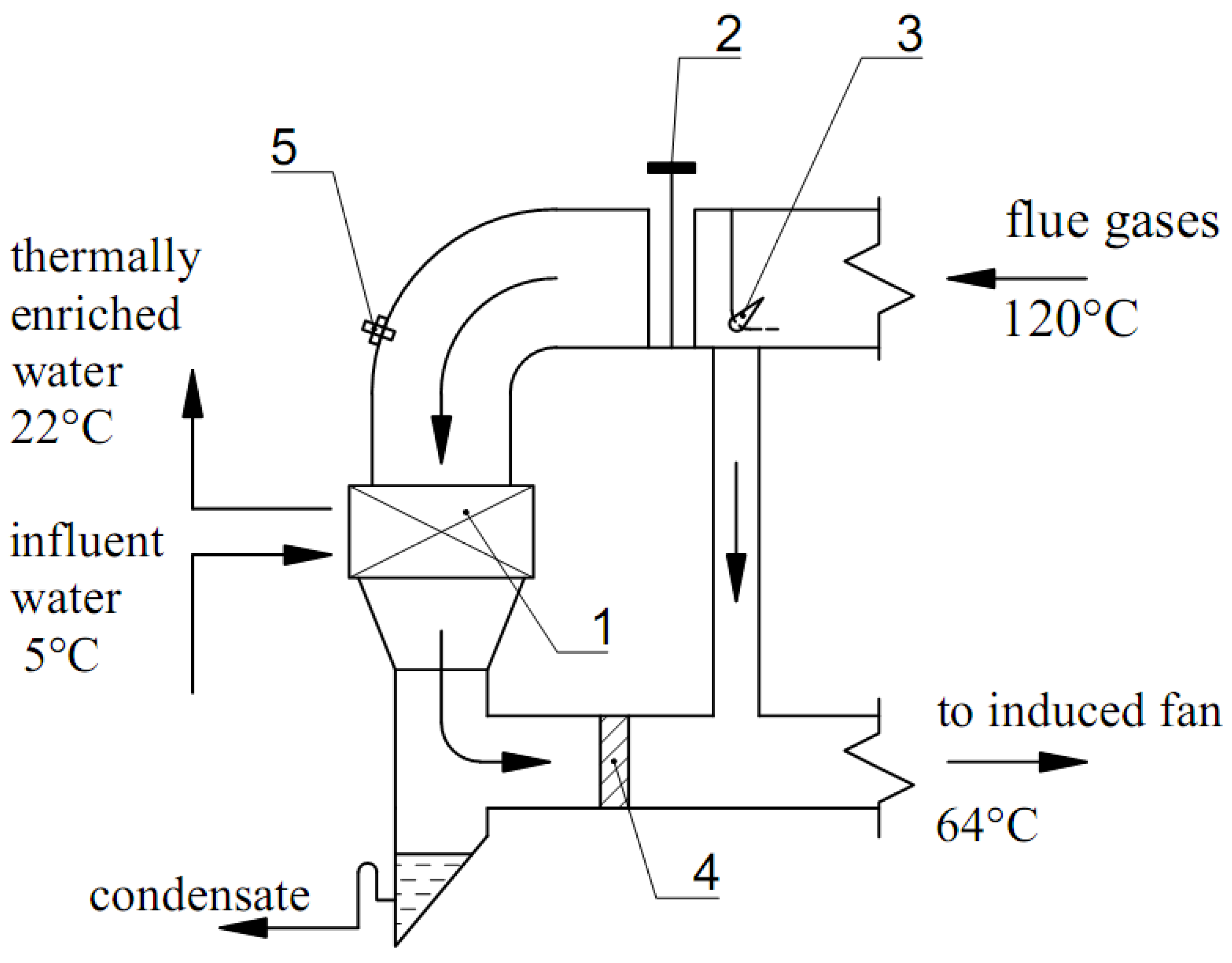
Figure 1 provides a diagram of the reuse of flue gas heat in a surface condensation heat exchanger. Flue gases flow from the economizer to the distribution valve. The valve divides the flue gas flow into two streams. The main flow passes through the strainer into the heat exchanger. The second stream goes through the bypass line into the flue.
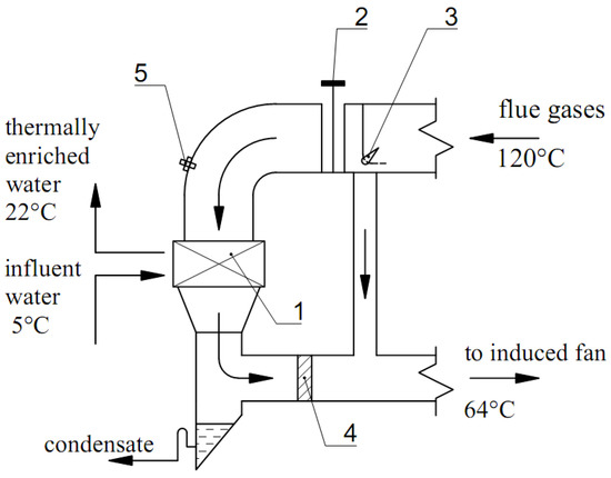
Figure 1.
Scheme of reuse of flue gas heat in a condensing surface heat exchanger: 1—condensing surface of the heat exchanger; 2—strainer; 3—distribution valve; 4—drip collector; 5—hydropneumatic supercharger.
Heat exchange reduces the humidity of combustion products and condensate. After mixing, the flue gas temperature is maintained above the condensation point. Accordingly, the formation of condensate in the flue is excluded.
Condensate is collected in a pan. Then it enters the degassed water tank, bypassing the water treatment plant. Pumps supply water (condensate) from the tank to the deaerator with a closed-type heat supply system.
2.2. Method of Calculation for Increasing the Efficiency of Boilers
Multiple versions of hot water boilers of various capacities were reviewed. Two Logano sk755 boilers of different capacities were installed in each boiler room. The calculated data were taken from the technical dossier of the boiler. The main characteristics of the boiler are presented in Table 1.

Table 1.
The technical characteristics of boilers and boilerhouses.
Natural gas is used as fuel for the Urengoy field. The calculation of the condensation surface heat exchanger was carried out according to the method. The presented technique helped to evaluate the efficiency of the installation of a condensing heat exchanger.
Calculate the flue gas volume of the inlet heat exchanger under standard conditions, VN (m3/s):
where αFG is a coefficient of excess air in flue gases (dimensionless coefficient), QB is a boiler heating capacity (MW), and ηLB is a boiler efficiency at a lower calorific value (dimensionless value).
The actual volume of flue gases of the output heat exchanger in the field, V1t = VFG(m3/s), is:
where tFG is the flue gas temperature of the outlet heat exchanger (°C).
Average volume flow rate of flue gases of the output heat exchanger VAVG (m3/s):
Mass consumption of flue gases, GFG (kg/s), is:
where ρN is the density of the average flue gas composition under common terms and conditions, (1.295 kg/m3).
Enthalpy of gases at the inlet to the heat exchanger I1 (kJ/kg):
where CCP is the thermal capacity of dry burning products (kJ/(kg·°C), CWV is the thermal capacity of water vapor during combustion (kJ/(kg·°C), tCP is burning product temperature of the outlet heat exchanger (°C), and χCP is water content products of burning of the output heat exchanger (kg/kgCP).
Let us determine the amount of combustion products taking into account the water at the outlet of the heat exchanger χCP (kg/kgCP):
where χFG is water content flue gases of the output heat exchanger (kg/kg).
Enthalpy of gases at the inlet to the heat exchanger IFG (kJ/kg) is:
Let us determine the amount of water in the flue gases at the outlet of the heat exchanger χFG (kg/kgCP):
Heating capacity of the heat recovery unit QU (kJ/s):
Amount of heated water GW (kg/s):
where CW is the thermal capacity of water at a medium temperature (kJ/(kg·°C), and tW2 and tW1 are temperatures of heated water (°C).
Average temperature drop Δt:
where Δtmax is the difference between tFG1 and tW1 (°C); Δtmin is the difference between tFG2 and tW1 (°C).
Characteristic heat transfer index of the heat exchanger K (W/(m2·°C):
where α’FG is decreased thermal transfer ratio from flue gases to the external surface of the condensing heat exchanger (35, W/(m2·°C)), δ is the wall thickness (m), λ is a thermal conductivity of the material (W/(m·°C), and αIN is a coefficient of heat transfer from the internal surface of the tube to the warmed-up water (1000, W/(m2·°C)).
Heat transfer surface of the heat recovery unit F(m2):
Number of heat recuperator pipes N:
where fi is the thermal transfer surface of one pipe (0.0025 m2).
Number of tube packages z:
where ni is the number of tubes in one bank (50).
Height of the heat recovery unit H(m):
where dOD is the outside diameter of tubes (m).
The amount of useful heat used by the heat exchanger QUU (kJ/s):
Let us determine the efficiency of the boiler without heat recovery installation at high calorific value:
where B is a fuel consumption (m3/s).
Increasing the efficiency of the boiler with the help of a heat recovery unit Δη:
Total efficiency of one boiler ηT (percent):
Calculations are set out in Table 2.
Table 2.
The outcome of the calculation of improving the effectiveness of boiler houses.
Therefore, it is possible to identify the common range of increase in the maximum values of boiler performance computed according to the proposed procedure. The calculations obtained showed that the boiler power does not affect the increase in boiler efficiency. The average value of the boiler efficiency increase is 1.2 percent. The installation of a heat exchanger is one of the most affordable methods of increasing the efficiency of the boiler house, which is especially important at present with a high demand for high-efficiency equipment. This approach to improve energy performance can be studied for low-power boilers, for example, for boiler houses located near residential areas. As a result, the installation of a heat exchanger improved the effectiveness of the boiler and reduced the sum of gases that influence thermal pollution of the environment.
3. The Main Part
3.1. Development of an Installation for Heat Recovery and Reduction of Carbon Dioxide Emissions
Figure 2 shows a diagram of the gas–air path of a steam boiler for burning natural gas and fuel oil with a flue gas recirculation system. The main product of the boiler, superheated steam, is obtained by flaring liquid or gaseous fuel in the furnace chamber 1. Then fuel together with the air is heated in the air heater 6 through wall burners 16. The water is heated first in the economizer 3. Water starts to evaporate in the screen pipes 4 of the furnace 1, and overheating of the steam generated in the superheaters 5 occurs. The steam is heated to the specified operating conditions of the turbine parameters. There are several ways to regulate the steam temperature. One of them is a method for regulating the temperature of superheated steam at the outlet of superheaters 5 by changing the flow rate of a mixture of flue gases and hot air entering through the flue 11 into the nozzles 12. The nozzles are located on the walls of the boiler in the lower raised part of the furnace 1 under the burners 16. Flue gases are taken from the connecting flue of the boiler 7 by fans 10 while hot air is taken from the ducts 15 and 17 toward air heaters 6. The use of an air additive allows one to maintain an oxidizing environment in the elevated area. This reduces the activity of metal corrosion, soot formation and coking, manifested at low excess air in the burners αb ≤ 1.05. This is typical for the combustion of natural gas and fuel oil. In addition, it becomes possible to minimize the consumption of flue gases and the energy consumption of fans 10 by regulating the temperature of superheated steam tss consumption of the hot air additive. To reduce the temperature unevenness in the flow of combustion products, nozzles 13 are installed in front of the superheaters 5. These nozzles are located on the walls of the boiler in the upper part of the combustion chamber 1, into which, it should be noted, flue gases or their mixture with air are also fed. Separate and simultaneous operation of the lower and upper nozzles 12 and 13 is possible. When installing a gas-turbine generator at a CHP, the boiler shop is equipped with a discharge flue 18. The products of complete combustion spent at the back pressure pgt from the gas-turbine generator enter the flue 18. These products are sent from it through the flues of the additive 19 into the flue gas recirculation flue 11 and into the nozzles 12 and 13. The fans 10 are turned off and are in reserve. The temperature control of the superheated steam tss is still carried out by the consumption of the gas–air mixture with the constant consumption of the supplied combustion products with a low oxygen content O2 ≤ 4.0 percent, with a commensurate temperature level of gases behind the economizer at the point of selection for recirculation and behind the turbo-electric generator at the temperature of trec ≈ tgt = 330–430 °C. The deviations of the tss continue to be eliminated by the consumption of hot air additives from the duct 17. The temperature behind the gas turbine can be at a higher level of tgt > 430 °C. At the same time, cold air is added to the flue 11 through the duct 20. During normal operation of the boiler, the consumption of the substituted combustion products should be commensurate with the flow characteristics of the fans 10 in the initial modes. The total number of boilers involved in the combined technology is m ≥ n + 1, where n = Vgt/Vrec is the number of working boilers, and Vgt and Vrec are the gas consumption behind gas turbines and boiler recirculation, m3/s. The working fraction of recirculating gases r = 0.30–0.35. Then combustion products with a flow rate of Vgt ≈ rVb ≈ Vb/3 will flow to each working boiler from the built-in gas-turbine electric installations, where Vb is the flow rate of flue gases behind the boiler, m3/s. The choice of the capacity of the built-in power plant according to the considered technology of combined heat and electric power generation at the design stage should be linked with the organization of the discharge of combustion products, that is, based on the capabilities of the existing boiler equipment of the CHP. The supply of combustion products to the nozzles 12 and 13 according to the new technology is carried out due to the pressure of gas-turbine units with the fans 10 turned off, which forms savings for the needs of the CHP ΔErec. The discharge of gases into the atmosphere is carried out in common boiler flows by smoke exhausters 8 with a flow overload Vb/3 and an increase in energy consumption of ΔEen. Nevertheless, ΔEen < ΔErec, since the volume of combustion products cooled in boilers up to tex ≈ 120–140 °C becomes smaller. The main effect of the integrated technology is also realized here—reducing heat losses with outgoing gases. The project of transferring the CHP to a new technology provides an emergency discharge of combustion products into the chimney and a calculated check of the latter for the release of additional gas volumes.
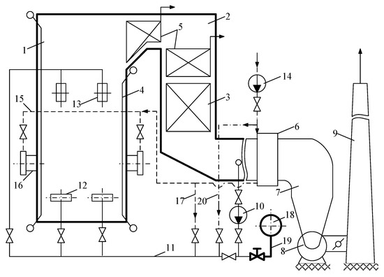
Figure 2.
Scheme of an industrial gas-and-oil boiler with recirculating devices and added intake of complete burning products: 1—furnace; 2—flue with convective heating surfaces; 3—economizer; 4—screen pipes; 5—superheaters; 6—external air heaters; 7—connecting flues of the boiler; 8—smoke exhausters; 9—chimney; 10—boiler flue gas recirculation fans; 11—boiler flue gas recirculation flue; 12—lower flue gas nozzles for regulating the temperature of superheated steam behind superheaters 5; 13—upper flue gas nozzles to reduce temperature unevenness in combustion products leaving furnace 1 in front of superheaters 5; 14—boiler blast fans; 15—boiler air ducts; 16—gas–oil burners; 17—hot air additive air duct; 18—gas outlet for the discharge of complete combustion products from the gas-turbine generator; 19—gas outlet for the additive of complete combustion products combustion from a gas-turbine electric generator; 20—cold air additive duct.
A positive impact is also obtained when the heated air streams are replaced by combustion product flows from gas-turbine power plants during the implementation of an event related to heating gases leaving the boiler above the dew point temperature and preventing low-temperature corrosion (Figure 3a).
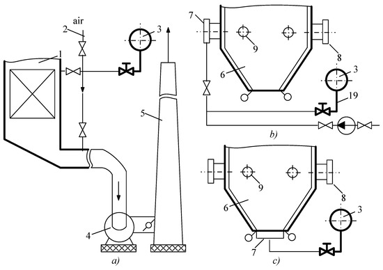
Figure 3.
Schemes for the use of combustion products in the technologies of existing boilers: (a) replacement of hot air with full combustion products to eliminate low-temperature corrosion; (b) replacement of blast furnace gas with incomplete combustion products; (c) dispersal of reagent input with the supply of incomplete combustion products through hearth burners and air and natural gas flows through nozzles on the walls of the furnace; 1—flue gas boiler; 2—hot air pipeline; 3—flue discharge of combustion products from the gas-power sector; 4—flue pumps; 5—chimney; 6—furnace; 7—burners with nozzle input of low-reaction fuel-containing gases sealed with inert products; 8, 9—nozzles for air and natural gas input.
Note that the heat-substituting technologies according to Figure 3a do not have a practical effect on the combustion process.
It is reasonable to link the removal of incomplete combustion products from gas-turbine power plants with the discharge into boilers burning industrial gases heavily ballasted with inert agents (Figure 3b). This can be, for example, blast furnace gas supplied to the CHP from the industrial sector after ore processing. Replacing one type of low-reaction fuel-containing gas with another does not lead to a serious change in the flare process and the parameters of heat losses laid down by design changes. Simultaneous transition to fuel combustion technology with dispersed input of reagent flows into the furnace 6 through nozzles 7, 8 and 9 placed on its walls will provide an additional reduction in heat losses with exhausted gases. The experience of dispersed input of incomplete combustion products and air can also be used according to another scenario: ballasted fuel flows through hearth burners 7 and gas and air through wall nozzles 8 and 9 (Figure 3c). In all cases of transition to the dispersed input of reagent flows into the furnace, an additional economic gain is formed, caused by a decrease in the temperature level of the torch and improved operating conditions of burners and superheaters, an extension of the service life between repairs, a decrease in the output of harmful nitrogen oxides and an expansion of the operating range of thermal loads of boilers.
3.2. Scientific Novelty
The scientific novelty of the study is presented by the authors in the analysis of theoretical studies of the process of condensation of the water vapor of outgoing flue gases and recommendations for further development of research. In addition, a method of thermodynamic and exergetic calculations based on the balances of the amount of energy during the utilization of the heat of condensation of water vapor at a constant partial pressure of outgoing flue gases was developed. The authors also note the expansion of the theory of condensation heat transfer in relation to solar collectors and a heat exchanger installed behind the power units of thermal power plants.
The developed methodology for calculating the economic efficiency of using a contact heat exchanger, as well as renewable energy sources as additional methods for obtaining electrical and thermal energy and cold, is based on new scientific approaches but using fundamental laws of physics, mathematics and thermodynamics.
The scientific novelty also lies in the development of a new scheme for using the heat of the exhaust gases; the authors describe this in detail in the next subsection.
3.3. Description of the Proposed Technology
Consider an installation implementing a method of absorption of flue gases in a contact heat exchanger with subsequent heating (Figure 4).
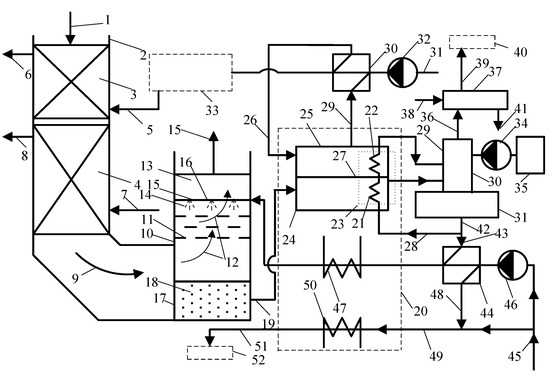
Figure 4.
Installation of combined greenhouse gas capture technology.
The outgoing flue gases 1 after the superheater of the power boiler unit with natural circulation of the steam-water medium enter the downpipe 2 with convective heating surfaces 3 and 4. In the economizer 3, feed water 5 is heated, which enters the boiler unit after the thermal preparation system. The heated feed water 6 enters the boiler drum. Atmospheric air 7 is pumped into the air heater 4 by a blow fan. The heated air 8 is sent to the fuel supply system, the burner device or directly to the furnace, depending on the type of fuel being burned and the fuel preparation system. In convective surfaces 3 and 4, flue gases are cooled to a temperature of 110–140 °C. The gases 9 cooled to this temperature are sent to a convective heat exchanger 10 with a passive nozzle 11. In the heat exchanger 10, flue gases 12 pass through a passive nozzle 12, into which cooled water 14 is sprayed from the upper part 13 of the heat exchanger from nozzles 15 connected to the pipeline system 16. The water sprayed by the nozzles 15 and 14 reacts with the flue gas components 13. Part of the triatomic gases, primarily CO2, as well as NOx and SOx, are adsorbed by water 14 and flow into the lower part 17 of the heat exchanger 11. The water saturated with gases 18 is sent through the pipeline system 19 to the advanced absorption Li-Br refrigerating machine (absorption refrigerator) 20.
A distinctive feature of absorption refrigerator 20 is the existence of a solar radiation heating unit. Heating elements 21 and 22 of absorption refrigerator 20 are combined into one unit 23. Element 21 is installed in the heating compartment 24 of gas-enriched water 18. Element 22 is established in the heating chamber 25 of water 26. Chamber 25 is warmed by solar radiation. The top part of the chamber 25 can be made of a convex or concave parabolic shape. Compartments 24 and 25 are separated by a partition 27. Thermally treated feed water 28 circulates in the heating unit 23. The water heated 29 in compartment 25 is sent to the heat exchangers 30 of the chemical water treatment unit. The source water 31 is pumped through the chemical treatment unit by a pump 32 and sent to the thermal treatment unit 33. The unit 33 includes the main deaerator and heat exchangers (not shown in the figure). From block 33, feed water 5 is sent to the economizer 3 of the boiler unit. The circulating water cooled in block 23 28 is directed to an auxiliary deaerator 29, consisting of a deaeration column 30 and a tank 31. For better desorption of CO2, a solution of monoethanolamine is injected into the deaerator 29 by a metering pump 34 from the tank 35. The vapor 36 of the deaerator 29 is sent to the tank 37, into which a solution of calcium chloride 38 is injected, necessary for the separation of NOx and SOx. Gases 39 are removed from the tank 37 and sent to the separation unit 40 (not shown in detail in the diagram). From tank 37, a mixture of the obtained materials 41 is removed for recycling. From the tank 31, the heat-treated water 42 is divided into two streams 28 and 43. The flow 43 is directed to the heat exchangers 44 of the raw water treatment unit 45, pumped by the pump 46. After the heat exchangers 44, the water must be cooled in the evaporator 47 of absorption refrigerator 20. The source water 45 is mixed with water 48 after the heat exchangers 44. The mixture of streams 49 is sent to the absorber 50 of absorption refrigerator 20. The water heated in absorption refrigerator 20 51 is directed to the heat pump 52 (not shown in detail in the diagram).
4. Discussion
Of course, there are similar methods of combined generation of electricity, heat and cold in the trigeneration cycle of a hybrid thermal power plant for industrial enterprises. Such hybrid power plants may include solar collectors, wind and micro-gas-turbine installations, an absorption refrigeration machine or a heat pump. The advantage of such a combination is a reduction in the cost of generating electricity and cold, resource conservation of organic fuel or a complete rejection of organic fuel and the transition to green energy.
The closest analogue of the installation proposed by the authors is a complex for the combined generation of electricity, heat and cold in the trigeneration cycle of a hybrid thermal power plant for industrial enterprises, containing a turbo expander, a condenser, an evaporator, a solar collector and a refrigeration chiller. The method is implemented by heating a low-boiling coolant due to the high intensity of solar radiation in the solar collector, directing the steam of the low-boiling coolant into the turbodetander and converting the potential steam energy into mechanical energy of rotation of the turbodetander shaft and into electrical energy in an electric generator connected by a coupling to the shaft.
The method of generating electricity, heat and cold considered by the authors of this article differs in the developed theoretical, applied and economic aspects. The developed methodology makes it possible to identify options for optimizing the use of organic fuels, reduce the amount of greenhouse gas emissions into the atmosphere and compare the economic indicators of the use of renewable energy sources. Such energy sources include a heat pump, an organic Rankine cycle, an absorption-type refrigeration machine and solar collectors.
Thus, the overall range of increasing the efficiency of energy supply is possible with an energy and technological combination. The main advantages of the organic Rankine cycle are as follows. As noted earlier, organic liquids usually remain superheated at the end of expansion. Thus, there is no need for overheating in the organic Rankine cycle. A positive feature of the development is the low temperature of heat recovery. In addition, the Li-Br absorption machine makes it possible to improve the conditions of permanent storage of agricultural products and the work of personnel.
5. Conclusions
On the basis of the developed schemes for the utilization of the heat of condensation of water vapor, principles for the introduction and management of reliable and environmentally friendly technologies can be created when using the designs of world concerns as the basis of combined-cycle gas installations. Based on the results of the research, the following conclusions can be drawn.
1. Agricultural and processing complexes for various purposes assume the presence of service personnel in the field of heat and electricity. The main devices for obtaining process steam and hot water are steam and hot water boilers operating at nominal capacity during the heating period. In order to increase efficiency, a research methodology was developed, and an analysis of the flue gas cooling method was carried out.
The variant of intensification of heat exchange processes in convective chimneys was calculated, which will reduce the consumption of natural gas, increase the share of using unconventional and circulating energy resources and reduce the amount of harmful emissions into the atmosphere.
2. A methodology was developed to assess the possibility of using a flue gas recovery system, in particular contact heat exchangers, Li-Br absorption refrigerating machines, heat pumps and the organic Rankine cycle in agricultural systems with high energy consumption, as well as low-power mini-CHP. This technique is interesting because it can be integrated into the exergoeconomical analysis of the efficiency of using the heat of the soil and groundwater as an energy source.
3. From a practical point of view, the authors developed recommendations for optimizing the parameters of exhaust gases behind steam boilers and gas turbines. In addition, according to the developed methodology, the economic efficiency of reducing the consumption of natural gas to the power unit is calculated, provided that the technology of heat recovery of water vapor condensation is implemented. It should be noted that the authors are developing schematic diagrams for the use of solar collectors, heat exchangers, absorption machines and ORCS behind the power units of thermal power plants running on natural gas.
Author Contributions
Conceptualization, K.O. and S.A.; Data curation, K.O.; Formal analysis, K.O.; Funding acquisition, S.A; Investigation, K.O.; Methodology, K.O.; Project administration, K.O.; Resources, S.A.; Supervision, K.O. and S.A.; Validation, K.O. and S.A.; Visualization, K.O. and S.A.; Writing—original draft, K.O. and S.A.; Writing—review & editing, K.O. and S.A. All authors have read and agreed to the published version of the manuscript.
Funding
This research received no external funding.
Institutional Review Board Statement
Not applicable.
Informed Consent Statement
Not applicable.
Data Availability Statement
Not applicable.
Conflicts of Interest
The authors declare no conflict of interest.
Nomenclature
| αFG | coefficient of excess air in flue gases |
| QB | boiler heating capacity (MW) |
| ηLB | boiler efficiency at a lower calorific value |
| tFG | flue gas temperature of the outlet heat exchanger (°C) |
| ρN | the density of the average flue gas composition under common terms and conditions (1.295 kg/m3) |
| CCP | the thermal capacity of dry burning products (kJ/(kg·°C) |
| CWV | thermal capacity of water vapor during combustion (kJ/(kg·°C) |
| tCP | burning product temperature of the outlet heat exchanger (°C) |
| χCP | water content products of burning of the output heat exchanger (kg/kgCP) |
| χFG | water content flue gases of the output heat exchanger (kg/kg) |
| CW | the thermal capacity of water at a medium temperature (kJ/(kg·°C) |
| tW2, tW1 | temperature of heated water (°C) |
| Δtmax | difference between tFG1 and tW1 |
| Δtmin | difference between tFG2 and tW1 |
| α’FG | decreased thermal transfer ratio from flue gases to the external surface of the condensing heat exchanger (35, W/(m2·°C)) |
| δ | wall thickness (m) |
| λ | thermal conductivity of the material (W/(m·°C) |
| αIN | coefficient of heat transfer from the internal surface of the tube to the warmed-up water (1000, W/(m2·°C)) |
| fi | thermal transfer surface of one pipe (0.0025m2) |
| ni | number of tubes in one bank (50) |
| dOD | outside diameter of tubes (m) |
| B | fuel consumption (m3/s) |
| pgt | flue gas pressure, Pa |
| trec | flue gas recirculation temperature, °C |
| tgt | temperature behind the gas turbine, °C |
| tss | superheated steam temperature, °C |
| Vgt | volumetric consumption of combustion products behind a gas turbine, m3/s |
| Vrec | volume flow rate of recirculation gases, m3/s |
| Vb | volumetric gas flow through the boiler, m3/s |
| ΔEen | costs of electric drive units, EUR |
| ΔErec | savings from the use of recycling, EUR |
| tex | exhaust gas temperature, °C |
References
- Biryuzova, E.A. Investigation of Methods for Determining Heat Losses from External Cooling of Surfaces of a Small-Capacity Hot-Water Boiler. IOP Conf. Ser. Mater. Sci. Eng. 2018, 463, 032056. [Google Scholar] [CrossRef] [Green Version]
- Batrakov, P.A.; Mikhailov, A.G.; Ignatov, V.Y. Fire-tube boiler optimization criteria and efficiency indicators rational values defining. J. Phys. Conf. Ser. 2018, 944, 012009. [Google Scholar] [CrossRef]
- Bukowska, M.; Nowak, K.; Proszak-Miąsik, D.; Rabczak, S. Concept of Heat Recovery from Exhaust Gases. IOP Conf. Ser. Mater. Sci. Eng. 2017, 245, 052057. [Google Scholar] [CrossRef] [Green Version]
- Proszak-Miąsik, D.; Rabczak, S. Methods for reducing low emissions from heating devices in single—Family housing. E3S Web Conf. 2018, 45, 00069. [Google Scholar] [CrossRef] [Green Version]
- Shatskikh, Y.V.; Sharapov, A.I.; Byankin, I.G. Analysis of Deep Heat Recovery From Flue Gases. J. Phys. Conf. Ser. 2017, 891, 012188. [Google Scholar] [CrossRef]
- Pashchenko, D.I.; Semenov, B.A.; Shchelokov, A.I.; Naplekov, I.S.; Mustafin, R.M. Thermodynamic analysis of thermochemical recuperation of high-temperature flue gas heat. J. Phys. Conf. Ser. 2018, 1111, 012009. [Google Scholar] [CrossRef]
- Osintsev, K.V.; Prikhodko, I.S.; Zavyalova, M.I. Methods for improving energy efficiency of air handling unit using factor analysis of data. IOP Conf. Ser. Earth Environ. Sci. 2018, 194, 052019. [Google Scholar] [CrossRef]
- Osintsev, K.V. Water Heater. Patent of the Russian Federation 2,476,779, 27 February 2013. [Google Scholar]
- Islamova, A.; Kerimbekova, S.; Shlegel, N.; Strizhak, P. Droplet-droplet, droplet-particle, and droplet-substrate collision behavior. Powder Technol. 2022, 403, 117371. [Google Scholar] [CrossRef]
- Kuznetsov, G.; Islamova, A.; Orlova, E.; Ivashutenko, A.; Shanenkov, I.; Zykov, I.; Feoktistov, D. Influence of roughness on polar and dispersed components of surface free energy and wettability properties of copper and steel surfaces. Surf. Coat. Technol. 2021, 422, 127518. [Google Scholar] [CrossRef]
- Osintsev, K.V.; Alyukov, S.V. Experimental Investigation into the Exergy Loss of a Ground Heat Pump and its Optimization Based on Approximation of Piecewise Linear Functions. J. Eng. Phys. 2022, 95, 9–19. [Google Scholar] [CrossRef]
- Abdelalim, A.; O’Brien, W.; Shi, Z. Development of Sankey diagrams to visualize real HVAC performance. Energy Build. 2017, 149, 282–297. [Google Scholar] [CrossRef]
- Karaağaç, M.O.; Kabul, A.; Oğul, H. First- and second-law thermodynamic analyses of a combined natural gas cyclepower plant: Sankey and Grossman diagrams. Turk. J. Phys. 2019, 43, 93–108. [Google Scholar] [CrossRef]
- Yang, M.-H.; Yeh, R.-H. Economic performances optimization of the transcritical Rankine cycle systems in geothermal application. Energy Convers. Manag. 2015, 95, 20–31. [Google Scholar] [CrossRef]
- Javanshir, N.; Mahmoudi, S.M.S.; Kordlar, M.A.; Rosen, M.A. Energy and Cost Analysis and Optimization of a Geothermal-Based Cogeneration Cycle Using an Ammonia-Water Solution: Thermodynamic and Thermoeconomic Viewpoints. Sustainability 2020, 12, 484. [Google Scholar] [CrossRef] [Green Version]
- Ahmadzadeh, A.; Salimpour, M.R.; Sedaghat, A. Thermal and exergoeconomic analysis of a novel solar driven combined power and ejector refrigeration (CPER) system. Int. J. Refrig. 2017, 83, 143–156. [Google Scholar] [CrossRef]
- Alabugin, A.; Osintsev, K.; Aliukov, S. Methodological Foundations for Modeling the Processes of Combining Organic Fuel Generation Systems and Photovoltaic Cells into a Single Energy Technology Complex. Energies 2021, 14, 2816. [Google Scholar] [CrossRef]
- Osintsev, K.; Aliukov, S.; Kuskarbekova, S. Development of Methodological Bases of the Processes of Steam Formation in Coil Type Boilers Using Solar Concentrators. Energies 2021, 14, 2333. [Google Scholar] [CrossRef]
- Osintsev, K.; Aliukov, S.; Prikhodko, Y. A Case study of Exergy Losses of a Ground Heat Pump and Photovoltaic Cells System and Their Optimization. Energies 2021, 14, 2077. [Google Scholar] [CrossRef]
- Liu, Q.; Wu, S.; Lei, Y.; Li, S.; Li, L. Exploring spatial characteristics of city-level CO2 emissions in China and their influencing factors from global and local perspectives. Sci. Total Environ. 2021, 754, 142206. [Google Scholar] [CrossRef]
- Wang, K.-L.; Xu, R.-Y.; Zhang, F.-Q.; Cheng, Y.-H. Reinvestigating the Spatiotemporal Differences and Driving Factors of Urban Carbon Emission in China. Front. Environ. Sci. 2022, 10, 309. [Google Scholar] [CrossRef]
- Vescovo, R.; Spagnoli, E. High Temperature ORC Systems. Energy Procedia 2017, 129, 82–89. [Google Scholar] [CrossRef]
- Tzivanidis, C.; Bellos, E. A Comparative Study of Solar-Driven Trigeneration Systems for the Building Sector. Energies 2020, 13, 2074. [Google Scholar] [CrossRef] [Green Version]
- Ochoa, G.V.; Isaza-Roldan, C.; Forero, J.D. Economic and Exergo-Advance Analysis of a Waste Heat Recovery System Based on Regenerative Organic Rankine Cycle under Organic Fluids with Low Global Warming Potential. Energies 2020, 13, 1317. [Google Scholar] [CrossRef] [Green Version]
- Gutierrez, J.C.; Ochoa, G.V.; Duarte-Forero, J. Regenerative Organic Rankine Cycle as Bottoming Cycle of an Industrial Gas Engine: Traditional and Advanced Exergetic Analysis. Appl. Sci. 2020, 10, 4411. [Google Scholar] [CrossRef]
- Xie, R.; Liu, W.; Chen, M.; Shi, Y. A Robust Operation Method with Advanced Adiabatic Compressed Air Energy Storage for Integrated Energy System under Failure Conditions. Machines 2022, 10, 51. [Google Scholar] [CrossRef]
- Osta-Omar, S.M.; Micallef, C. Mathematical Model of a Lithium-Bromide/Water Absorption Refrigeration System Equipped with an Adiabatic Absorber. Computation 2016, 4, 44. [Google Scholar] [CrossRef] [Green Version]
- Diaz, G.A.; Forero, J.D.; Garcia, J.; Rincon, A.; Fontalvo, A.; Bula, A.J.; Padilla, R.V. Maximum Power From Fluid Flow by Applying the First and Second Laws of Thermodynamics. J. Energy Resour. Technol. 2017, 139, 032903. [Google Scholar] [CrossRef]
- Yang, J.; Yang, Z.; Duan, Y. Off-design performance of a supercritical CO2 Brayton cycle integrated with a solar power tower system. Energy 2020, 201, 117676. [Google Scholar] [CrossRef]
- Sharan, P.; Neises, T.; Turchi, C. Thermal desalination via supercritical CO2 Brayton cycle: Optimal system design and techno-economic analysis without reduction in cycle efficiency. Appl. Therm. Eng. 2019, 152, 499–514. [Google Scholar] [CrossRef]
- Jung, D.; Lee, Y.; Park, B.; Kang, B. A study on the performance of multi-stage condensation heat pumps. Int. J. Refrig. 2000, 23, 528–539. [Google Scholar] [CrossRef]
- Gaigalis, V.; Skema, R.; Marcinauskas, K.; Korsakiene, I. A review on Heat Pumps implementation in Lithuania in compliance with the National Energy Strategy and EU policy. Renew. Sustain. Energy Rev. 2016, 53, 841–858. [Google Scholar] [CrossRef]
- Yan, G.; Bai, T.; Yu, J. Energy and exergy efficiency analysis of solar driven ejector–compressor heat pump cycle. Sol. Energy 2016, 125, 243–255. [Google Scholar] [CrossRef]
- César, J.C.; Ortiz, J.C.; Ochoa, G.; Restrepo, R.; Alvarez, J. A New Computational Tool for the Development of Advanced Exergy Analysis and LCA on Single Effect LiBr–H2O Solar Absorption Refrigeration System. Lubricants 2021, 9, 76. [Google Scholar] [CrossRef]
- Solano–Olivares, K.; Romero, R.; Santoyo, E.; Herrera, I.; Galindo–Luna, Y.; Rodríguez–Martínez, A.; Santoyo-Castelazo, E.; Cerezo, J. Life cycle assessment of a solar absorption air-conditioning system. J. Clean. Prod. 2019, 240, 118206. [Google Scholar] [CrossRef]


Publisher’s Note: MDPI stays neutral with regard to jurisdictional claims in published maps and institutional affiliations. |
© 2022 by the authors. Licensee MDPI, Basel, Switzerland. This article is an open access article distributed under the terms and conditions of the Creative Commons Attribution (CC BY) license (https://creativecommons.org/licenses/by/4.0/).