Review

Electro-Conversion of Carbon Dioxide to Valuable Chemicals in a Membrane Electrode Assembly

1
School of Environmental & Safety Engineering, Changzhou University, Changzhou 213164, China
2
Interdisciplinary Graduate School of Engineering Sciences, Kyushu University, Fukuoka 812-8582, Japan
*
Author to whom correspondence should be addressed.
Sustainability 2022, 14(9), 5579; https://doi.org/10.3390/su14095579
Submission received: 22 March 2022 / Revised: 24 April 2022 / Accepted: 26 April 2022 / Published: 6 May 2022
(This article belongs to the Section Sustainable Materials)

Abstract

:
Electro-conversion of carbon dioxide (CO2) into valuable chemicals is an efficient method to deal with excessive CO2 in the atmosphere. However, undesirable CO2 reaction kinetics in the bulk solution strongly limit current density, and thus it is incompetent in market promotion. Flow cell technology provides an insight into uplifting current density. As an efficient flow cell configuration, membrane electrode assembly (MEA) has been proposed and proven as a viable technology for scalable CO2 electro-conversion, promoting current density to several hundred mA/cm2. In this review, we systematically reviewed recent perspectives and methods to put forward the utilization of state-of-the-art MEA to convert CO2 into valuable chemicals. Configuration design, catalysts nature, and flow media were discussed. At the end of this review, we also presented the current challenges and the potential directions for potent MEA design. We hope this review could offer some clear, timely, and valuable insights on the development of MEA for using wastewater-produced CO2.

1. Introduction

Over the past two centuries, a tremendous amount of CO2 has been emitted into the atmosphere, and consequently triggered global warming [1,2,3]. Therefore, many methods have been proposed to tackle the excessive CO2 release and concentration. Among them, electrochemical CO2 reduction (ECO2RR) driven by renewable electricity has proven efficient in CO2 conversion and fixation [4,5].
ECO2RR is useful to produce value-added fuels, such as CO, HCOOH, CH3OH, CH3CH2OH, C2H4 [4]. Typically, ECO2RR is conducted in a cell consisting of two separated chambers for CO2 reduction and water oxidation (where oxygen evolution reaction, OER, occurs) [6,7]. Another three key elements also play an important role: anodic catalyst for OER, cathodic catalyst for ECO2RR, and a polymer membrane for room separation [7]. A power source extracts electrons from the cathode to the anode, and CO2 is reduced into chemicals at the cathode; at the same time, OER occurs at the anode [6,8]. As the first step, molecular CO2 is adsorbed onto the cathodic catalyst surface at the cathode, and subsequently undergoes initiation and turns into activated CO2 [4,7]. After a series of reactions, the C-contained product forms and its type is based on the exerted potential, catalyst species, and operation conditions. Equations (1)–(10) present common ECO2RR products at the cathode, and Equation (11) presents how oxygen evolution occurs at the anode [4,5,7].
2H+ + 2e → H2 (g)          E0 (V vs. RHE) = 0 V
CO2 + 2H+ + 2e → CO (g) + H2O     E0 (V vs. RHE) = −0.10 V
CO2 + 6H+ + 6e → CH3OH (l) + H2O   E0 (V vs. RHE) = 0.03 V
CO2 + 2H+ + 2e → HCOOH (l)       E0 (V vs. RHE) = −0.12 V
CO2 + 8H+ + 8e → CH4 (g) + 2H2O    E0 (V vs. RHE) = 0.17 V
2CO2 + 12H+ + 12e → C2H4 (g) + 4H2O  E0 (V vs. RHE) = 0.08 V
2CO2 + 12H+ + 12e → C2H5OH (l) + 3H2O E0 (V vs. RHE) = 0.09 V
2CO2 + 10H+ + 10e → CH3CHO (l) + 3H2O E0 (V vs. RHE) = 0.06 V
2CO2 + 8H+ + 8e → CH3COOH (l) + 2H2O E0 (V vs. RHE) = 0.11 V
3CO2 + 18H+ + 18e → C3H7OH (l) + 5H2O E0 (V vs. RHE) = 0.10 V
4OH → O2 (g) + 2H2O + 4e       E0 (V vs. RHE) = 1.23 V
Hydrogen evolution reaction (HER) is the main side reaction of ECO2RR and strongly competes with ECO2RR since their redox potentials are similar. Therefore, suppressing HER at the cathode is a great challenge to efficient ECO2RR. Additionally, traditional fossil fuel-derived products remain economically competitive in the global market [9,10,11]. High-pure CO and multi-carbon products (C2+) are usually of high interest due to their high market price, and recent efforts have also found useful catalysts in producing these high value chemicals [4,5,11,12,13,14,15,16,17]. For example, Guo et al. [16] electro-deposited coal-like porous Ag particles and obtained high-pure CO generation with 96.38% faradic efficiency (FE). Gao et al. [17] electro-converted CO2 into various C2+ chemicals via surface modification of Cu2O surface.
Great progress in catalyst design promoted the development of ECO2RR to a more competitive stand, but another shortage hinders further application. Gaseous CO2 is soluble to a limited extent in bulk solution with barely 0.033 mol/L. Thus the long diffusion distance in traditional H-type cell (Figure 1a) is detrimental to mass transport, and causes the limitation in current density to be below 100 mA/cm2 [18,19]. High current density matters in industrial production. An investigation by Sumit Verma et al. [20] found that current density over 200 mA/cm2 can generate positive profits based on techno-economical consideration. A membrane electrode assembly (MEA) configuration (Figure 1b) is an efficient means to tackle the undesirable current density in traditional bulk solution cell [6,7]. This configuration resembles a compacted H-type cell or, more vividly, is like a ‘sandwich’ [6,7,13,18]. This sandwich-like architecture comprises two flow lane-containing plates, a polymer ion-exchange membrane, a catalyst electrode for OER, and a gas diffusion electrode (GDE) to conduct ECO2RR. Due to the limited spare room for gas, anion, and cation transport, this configuration cuts the invalid resistant loss and strengthens the valid touch [7,18,21,22]. More impressively, this configuration also benefits current density to a higher level and usually beyond 100 mA/cm2 [7,11,18,21,23]. Zheng et al. [24] used a gas diffusion electrode to conduct ECO2RR, and achieved an ultra-high-pure CO product with nearly 100% FECO coupled with over 100 mA/cm2 current density. Jeong et al. [25] even operated a MEA at 300 mA/cm2 while maintaining CO selectivity at 99% FE. Other reports [12,13,14,16,26,27,28] also proved MEA to be a promising technology to promote commercialization of ECO2RR. However, recent systematic review on MEA remains rare despite significant advances in this field.
Herein, we first present some fundamental concepts of this structure and its key components. Then, the start-of-the-art modifications will also be discussed. Lastly, we conclude by highlighting the next stage of challenges that this front will meet. The objective is to promote and upgrade existing MEA technologies for CO2 electro-chemical conversion and provide guidelines in how to make it more competitive in the real energy market.

2. Configuration

2.1. Gas Diffusion Electrode (GDE) for ECO2RR

GDE is a special kind of porous membrane electrode with two different functional layers, namely, the gas diffusion layer (GDL) and the catalyst layer (CL) [22,23]. Usually, CL is deposited onto the GDL with a thickness of 50–100 nm which is much thinner than foil used in H-type cells with approximate 50 μm thickness [7]. The result is a much higher CO2 molecular concentration around the interface, favoring a higher current density operation [21,29,30,31]. Moreover, GDL is usually derived from a porous matrix, such as carbon cloth, and a pretty well-developed porous structure. The huge specific surface area of these materials makes them desirable for CO2 storage, thus significantly promoting the contact between catalysts and CO2 molecules [29,30,31]. Therefore, a comprehensive insight on the GDL and CL opens a revenue to understand role of GDE in ECO2RR.

2.1.1. Gas Diffusion Layer (GDL)

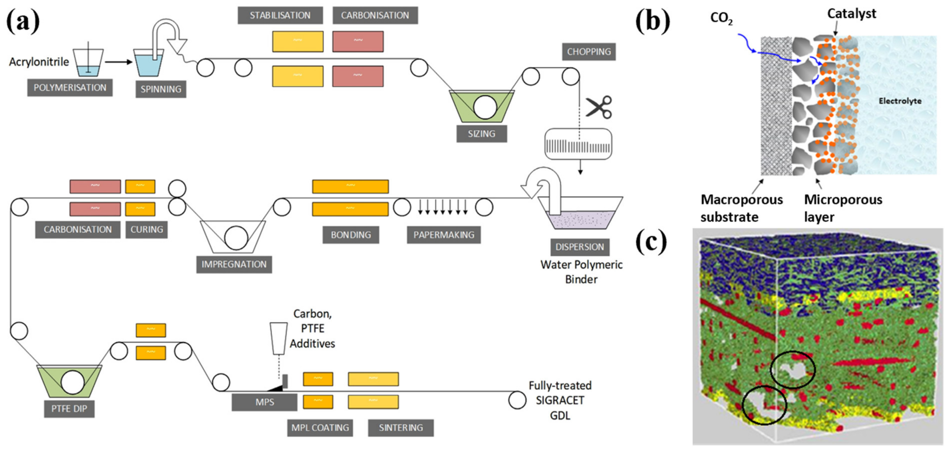
GDL manufacture has a long history and has matured for several years due to the spread of fuel cell technology over the world. The biggest and most sophisticated GDL manufacture firms are Toray® (Tokyo, Japan), Freudenburg® (Weinheim, Germany), Sigracet® (Weisbaden, Germany), Ballard® (Burnaby, BC, Canada), and CeTech® (Taiwan, China). Common GDL is made of carbonized polyacrylonitrile (PAN). An entire GDL fabrication usually comprises five processes: (1) Carbonization of carbon-based fiber: In this process, carbon-based fiber is to be heated at 1373–1623 K, with inactive N2 or Ar gas protection, to concentrate C coupled with O, H, N, etc. element deprivation. (2) Spin of carbon-based fiber into ordered piece goods: This process is key to the porosity and thickness of GDL. (3) Graphitization of the ordered piece good: The formed ordered piece good is heated again under sluggish N2 or Ar gas but at a higher temperature of 2473–3273 K. This process plays a big role in the conductivity and stability of the finished product. (4) Hydrophobic treatment: Polytetrafluoroethylene (PTFE) is usually used as a hydrophobic emulsion by dipping onto piece goods. (5) Paint of microporous layer: The microporous carbon fiber mixed with PEFE particles is painted onto one side of the piece goods, and then sintered at high temperature to remove PTFE particles, this layer is the key component in mass transport. In order to visualize the above five procedures, we refer the reader to a process flow diagram over a Sigracet GDL-producing process from the work of Adnan Ozden et al. [30].
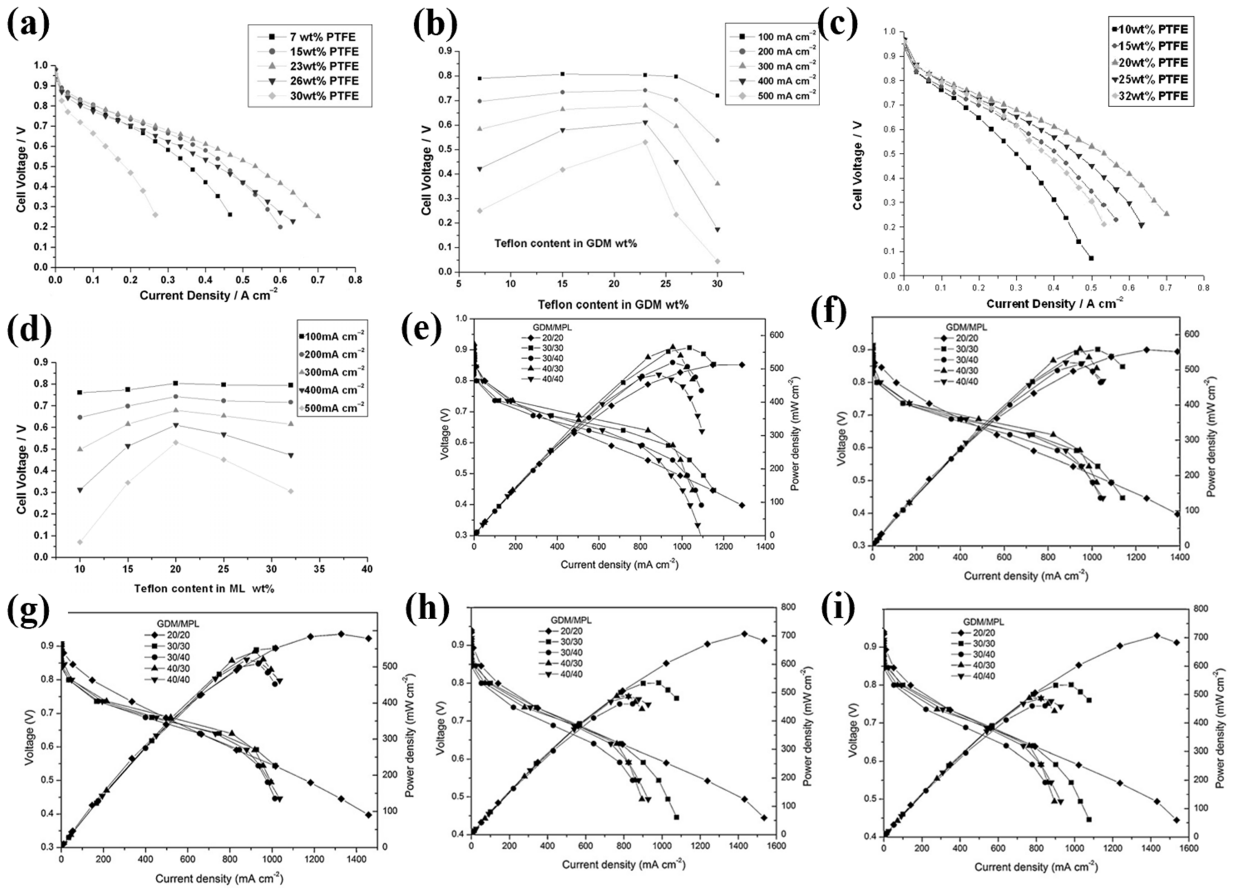
In the structure of GDL (Figure 2b), the two layers, macroporous substrate (MPS) and microporous layer (MPL), are for different purposes. MPS is a carbon-based matrix with randomly interconnected carbon fibers, which serve as a supporter for stability and flexibility [30]. The well-developed macroporous structure enables free gas transport as well as the electrons transfer. MPS presents a desirable porous inner structure with average pore size ranges of 20–100 μm due to the highly heterogeneous carbon-based matrix [31]. Hydrophobicity is important because it makes a delicate three-phase interface for ECO2RR, allowing sufficient contact between the reactant and the catalyst [32,33]. A common hydrophobic reactant is PTFE, but many reports also found that the uneven PTFE distribution on the MPS matrix incurred a concern over a decline in hydrophobicity. Others such as perfluorinated ether (PE), fluorinated ethylene propylene (PEP), and mixed fluorinated compounds also serve as considerably good hydrophobicity while maintaining surface uniformity. Despite some findings reported that an increase in PTFE content favored a better performance, this strategy should be under scrutiny due to inappropriate PTFE addition negatively affecting conductivity and thus the overall ECO2RR performance. Velayutham et al. [34] found that 20–25% wt PTFE addition served as optimal for conductivity and best cell performance (see Figure 3). Yet, in a Nafion-based membrane, a higher PTFE addition with 40% wt PTFE content in MPS and 30% wt of that in MPL led to optimal cell performance where operating temperature varied from 30 to 70 °C. This ratio provided a stable operation environment at a high current density 955 mA/cm2 while at a cell potential of 0.6 V [35].
MPL is a layer made of carbon powder and hydrophobic agent, directly combining the MPS and CL, but this layer is neither with a clear interface against MPS or against CL [30]. Due to the much smaller dimension of carbon particles, they usually penetrate into MPS to some extent, thus forming an interlocking interface between the two layers (Figure 2c). In a typical producing process, the precursor slurry containing carbon powder and hydrophobic agent are sprayed to a layer, and then heated several times to make the remaining hydrophobic agent volatile and to form a porous inner room [18,30]. The type of carbon powder and the ratio of carbon to hydrophobic agent are crucial factors determining the conductivity and microstructure. For carbon type, the conductivity and size should be paid close attention. Frequently employed materials concentrate on carbon black, acetylene black, graphite, etc., which are technically available and commercially affordable [36,37]. Alloy particles are also ideal materials, such as Ti deposited by IrO2 with good conductivity and corrosion resistance [38]. The size of particles matters. Many reports [18,30,32,39] found that the optimal size spanned from 5 to 20 μm, whereas larger particles were detrimental to gas transport and smaller particles were susceptible to electrolytes flooding. In addition to the appropriate size, reports on a relatively thinner MPL thickness making performance better also revealed the significance of MPL macroscopic dimensions [40]. As aforementioned with the effect of PTFE content in MPS, the ratio of carbon to hydrophobic agent still plays a big role in MPL performance; Orogbemi et al. [41] found that 20% PTFE and 80% carbon black was the most suitable recipe for gas penetration. Given the key role of MPL, a comprehensive analysis of each MPL component is primarily needed. However, there are few reviews in the EECO2RR field.
The last two paragraphs describe some details of MPS and MPL, respectively, but most of the details are based on the materials used in a fuel cell field. On the other hand, scholars’ focus tends to be on the whole gas diffusion layer rather than on separated MPS or MPL. Hence, comprehensive information should also be summarized. Generally, GDL is mainly made from carbon-based powder/fiber and a hydrophobic agent [30,37,41], whereas different preparation techniques determine four factors affecting ECO2RR performance, namely stability, hydrophobicity, conductivity, and thickness [18,30,31]. Commercialization requires a long-term and stable operation of instruments. Verma et al. [20] calculated that a 1-year stable operation is economically significant. One possible response to longtime stability is more hydrophobic agent addition, which protects the carbon-based matrix from flooding, especially a plausible collapse due to the tendency toward hydrophilicity of carbon-based matrix surface during long-term operation, especially at high current density [42]. However, this tactic suffers two drawbacks. One is the conductivity decline due to the insulating of the hydrophobic agent [30,34]. The other is the limited gas diffusion, as the average pore size narrows with increasing hydrophobic agent content, more condensed water is detrimental to gas diffusion in the narrowed space [30,43]. Therefore, the tradeoff within stability, hydrophobicity, and conductivity should be under scrutiny. Another consideration is focus on thickness. MPS is basically 180–400 μm [30] while MPL is basically 10–100 μm [39], and a common view supports a thinner GDL benefitting a better performance owing to lower electric resistance [40], but opinions on the reason for the lower electric resistance differ. Jeon et al. [44] found that the water permeation positively related to the GDL thickness, and a thick GDL meant more water saturation which did a disservice to gas transfer, hence a thinner GDL was more appropriate for utilization. Gao et al. [45] disagreed with the aforementioned opinion, their studies found that thickness was not the determination for permeation, whereas the porosity primarily exerted an effect in gas diffusion. Overall, GDL is a key component in supporting cell structure and promoting gas diffusion, yet the current focus is dominated by the CL with few studies deployed on GDL in ECO2RR; thus, the need is pressing. Hopefully, with more efforts toward GDL in the fuel cell field, we believe more types of GDL appropriate for ECO2RR MEA will emerge in the foreseeable future.

2.1.2. Catalyst Layer (CL)

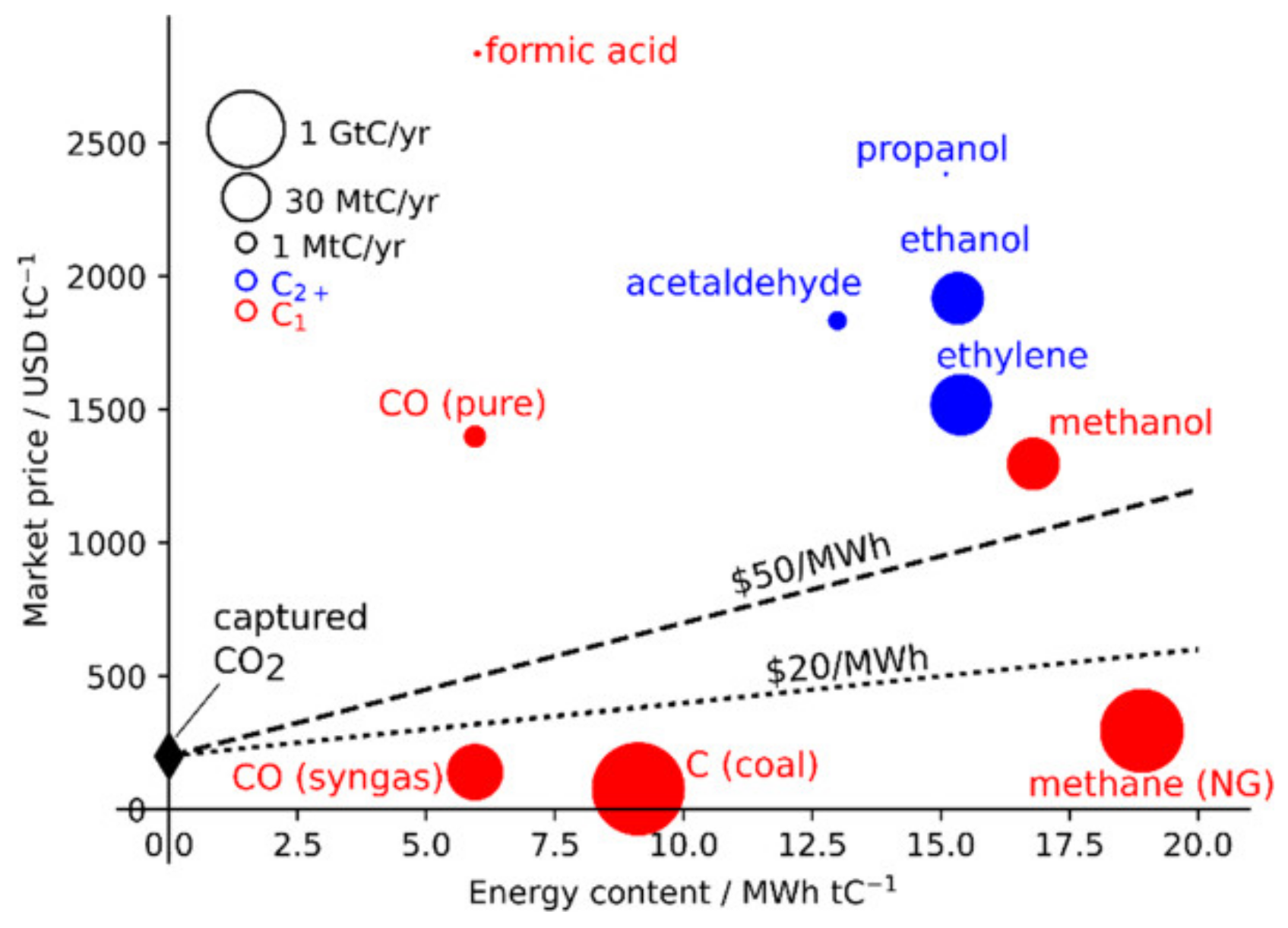
The catalyst is the most important component in ECO2RR, which directly determines product selectivity, production, purity, and configuration operation parameters. As such, a great deal of effort has been poured into novel and efficient catalyst design. Noticeably, capital market also plays a big part in the direction of ECO2RR study. Figure 4 demonstrates the links within global production, energy content, and market price, and a common sense is that market-preferred products—high price-added products—usually drive the study trend, and a growing dossier of evidence suggests that this is true. Current research mostly concentrates on two major classes of ECO2RR products. One is single-carbon products (C1) with low energy content but with alluring price, such as pure CO and formate. The other is multiple-carbon products (C2+) with high energy content and desirable market price simultaneously. Given this context, in this section, our discussions are product-oriented and focus on products with high market price and high energy content. Additionally, a summary on feedstock generation pathway and catalyst fabrication methods coupled with loading methods is also highlighted in this section.

Catalyst for Single-Carbon Products (C1) Generation

The recent focus on C1 derived from ECO2RR has been toward highly pure CO and formate. They are important feedstocks for chemicals or fuels production. However, only highly pure CO is competent mainly because the extra cost of purifying CO (syngas) is high. The impure gas products in CO (syngas) mostly concern H2 and CH4, thus suppression of hydrogen evolution reaction (HER) and CH4 generation stimulates great interests in this territory. Two tactics may respond to these concerns—the choice of catalyst kind and morphology strategy. Nitopi and co-workers [4] concluded on the selectivity towards products by several metals; after scrutinizing previous reviews, their reports highlighted that Pd, Ga, Ni, Cu, Pt, and Ti favored HER while Cu favored CH4 generation. Bagger et al. [46] summarized that metal of this kind has a negative adsorption energy for *H, a HER intermediate, and is thus liable to generate H2 during ECO2RR. Furthermore, Cu presents some distinct properties prone to generating not only H2 but also CH4. This may be derived from the unique positive adsorption energy for *H in contrast to the negative adsorption energy for *CO. The morphology strategy prominently refers to single-atom catalyst (SAC), especially for Ni SAC. Density functional theory calculations argued that the strong bonding energy between Ni SAC and CO is a result of lowered thermodynamic CO desorption rampart, and the result is a better record by Ni SAC than by Fe SAC or Co SAC [47].
Highly pure CO is an enduring topic in ECO2RR. Nitopi et al. [4] summarized some data from previous studies and found that Au, Ag, and Zn were three main metals in producing CO with high FE. Yang et al. [48] developed trisoctahedron gold nanoparticles with 50 nm diameter (Figure 5a) for high CO2 towards CO electro-conversion with 88.8 % FE. They also found that FECO varied with the Au particle size, and there was a decline to 62.13% by the Au particle with 100 nm particle size (Figure 5b). Liu et al. [49] even combined Au and Ag particles for ECO2RR. This complex Ag@Au core-shell nanoparticle (Figure 5c) was proven as an excellent catalyst with a high record for nearly 100% FECO (Figure 5d). However, the exorbitant price of Au and Ag particles compels attention towards cheaper catalysts. Zn is a good substitute metal to Au or Ag, its cheapness makes it fairly attractive. Luo et al. [50] synthesized a hexagon Zn catalyst and a satisfactory performance was achieved with 91.6% FECO under 200 mA/cm2 operation (Figure 5e). However, the poor activity of Zn usually calls for a higher over-potential or complex modification [51]. In Luo et al.’s [50] work, the hexagon Zn was synthesized via reconstruction of hexagon ZnO (Figure 5f), a complicated process that needs accurate tunning. Another drawback of Zn is that Zn is a relatively active metal compared with Au and Ag; that is to say that Zn may not be a strong acid-resistant catalyst, and this also calls for a further investigation for the long-term stability for the Zn catalyst.
Ni SAC is another topic catalyst for highly pure CO generation. Strategies for Ni SAC tuning have made significant progress in CO2 to CO conversion. Jeong and co-authors [25] used the Stober method as a hard template to synthesize a porous carbon-containing Ni SAC (Figure 5g), performing well with a record high 99% FE for CO while at a market-preferred 300 mA/cm2 in a MEA configuration (Figure 5h). In general, common precursors for SAC are MOFs [52], carbon nanotubes [53], graphene oxide [54], and other expensive carbon-based materials [25], thus generating a need for cheaper substitution. Zheng et al. [24] applied cheap carbon black (Figure 5i), replacing other expensive carbon as a precursor for Ni SAC production on a large scale. Batch experiments results justified the tactic as efficient with nearly 100% FE for CO in a MEA. Afterwards, when putting this Ni SAC into a modular cell with 10 × 10 cm2, the overall current climbed up to more than 8 A while maintaining an exclusive CO evolution with 3.34 L/h generation rate (Figure 5j). Interestingly, the other reported Ni SAC seems to prefer N-doping carbon-based materials. An ordinary view argues that N-doping breaks the charge neutrality and promotes electrons transfer in the carbon-based materials, so the ECO2RR performance is enhanced [24,55,56]. Aside from this point, another opinion endorses that high temperature generating pyridinic-N during N modification serves as a good binder for CO2 or other key intermediates, leading to a better performance [55].
Formic acid/formate is a crucial intermediate for chemicals drugs and pesticides synthesis [56], the price of formic acid/formate is around 2750 USD dollars per ton [4], making it attractive for production. With numerous experimental and theoretical efforts in studying the formation pathway, a general formic acid/formate generation pathway has been obtained as Figure 6a shows. At the first step, electrons bombard the adsorbed CO2 to form *CO2, then the O element of *CO2 binds the metal and is protonated into *OCHO, and finally it transforms to formic acid/formate [56,57,58]. We scanned 134 research papers within the last 5 years from ScienceDirect, RSC publications, and Wiley Online Library, and listed the number of papers of different used metal catalysts for formic acid/formate formation in Table 1. Apparently, the most studied metals for formic acid/formate are Sn, Bi, Cu, and Pb metals, which may be the result of relativity high selectivity for formic acid/formate by these metals, and analysis by Ding et al. [56] and Philips et al. [58] also verified this point of view. Ding et al. [56] listed several studies about the four metals for CO2 to formic acid/formate conversion, and >90% FE for formic acid/formate demonstrated their satisfactory catalysis performance. Interests in electrochemical reduction of CO2 to formic acid/formate have prevailed in the last five years, but there are still a few studies [59,60,61,62,63] of this conversion being carried out in MEA configuration despite excellent performance obtained in H-type cells. Another issue also challenges MEA application in CO2 to formic acid/formate electrochemical conversion. Selectivity to single or pure products matters, but compared with H-type cell, MEA seems to suffer a decline in selectivity or purity especially at a higher current density. Díaz-Sainz and co-workers [63] investigated the linkages within Q/A (electrolyte flow/area), formate concentration, and FE, the visualization of the results are as Figure 6b,c presents. Higher Q/A was able to drive a higher FE for formate but at the cost of lower formate concentration, and this inner link seemed to enlarge as current density approached higher values. Impure products overshadow the commercialization application of CO2 electro-catalysis technology, particular in a fierce cost performance-driven market. A delicate design in MEA by Wang’s group [64,65] efficiently responded to the impurity challenge while achieving high current density (partial current density 450 mA/cm2 for formate) and FE (maximum FE was 97% for formate). In their configuration [64], a solid porous styrene-divinylbenzene copolymer electrolyte was sandwiched between anion and cation membrane for formic acid generation and brief residence, while N2 and H2 were a flow carrier of formic acid and a proton donor, respectively. The final formic acid concentration was nearly 100% wt, arguably recently becoming the best record ever made.

Catalyst for Multiple-Carbon Products (C2+) Generation

Multiple-carbon products (C2+) are of high energy content and market price. The rearrangement of element C, O, and H for C2+ generation requires a larger over-potential and a more complicated intermediate step than that for C1. Unlike various kinds of metal catalysts for ECO2RR to C1, the generation of C2+ has a unique preference for Cu and its deriving catalysts. As the only single metal with negative adsorption energy for *CO but a negative adsorption energy for *H, it may be the reply to this unique preference. Hence, an in-depth survey on C2+ generation pathway features primarily in producing targets. In this section, we first give an overview of the currently studied pathways for a better understanding of ECO2RR, and several key parameters, includingfacets sensitivity, chemical states, operation potential, just to name a few, are also to be mentioned. Subsequently, several topic C2+ are discussed in detail.
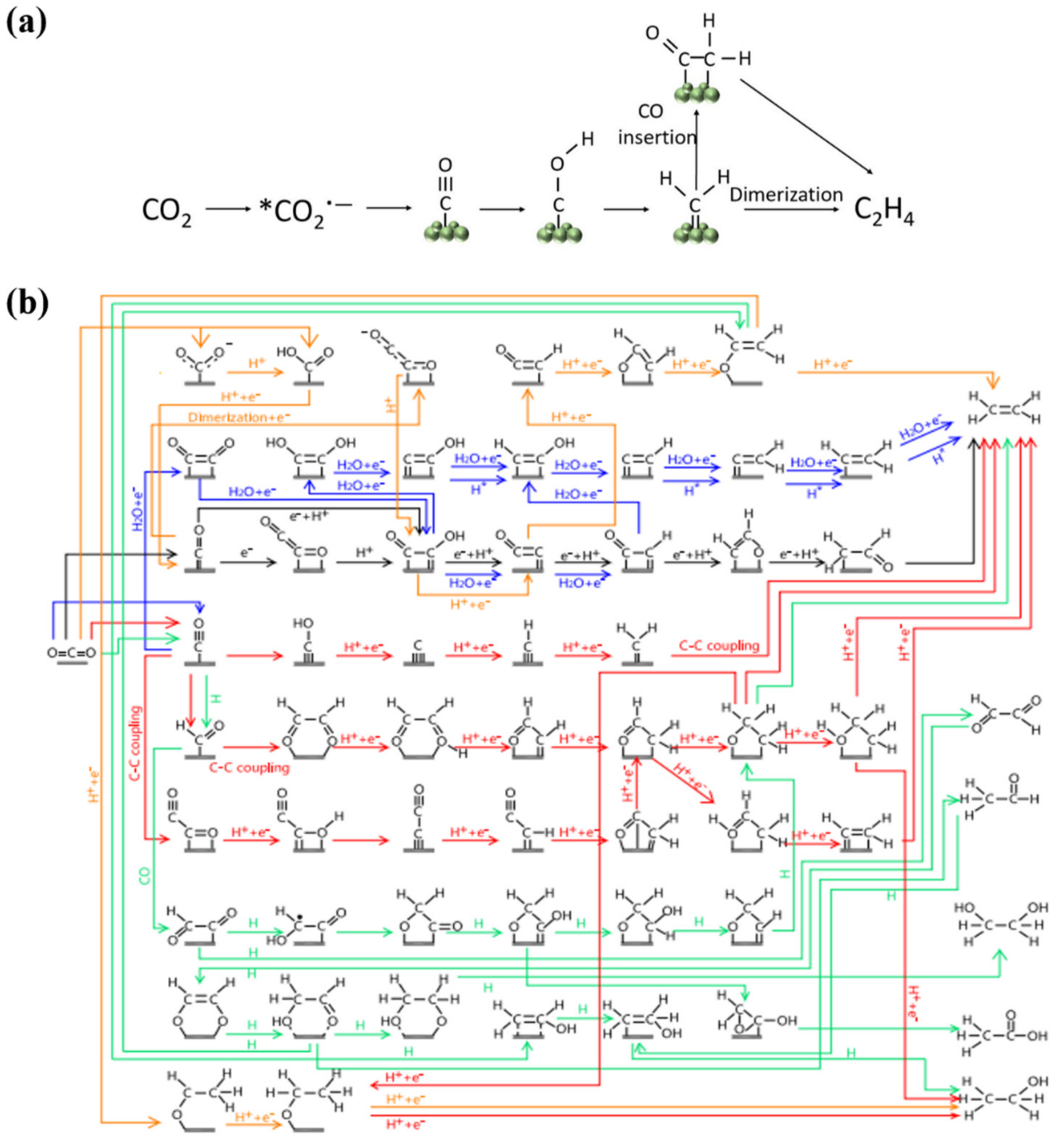
Cu is the sole single metal for ECO2RR to C2+, while unfortunately, inferior selectivity of Cu makes ECO2RR products complicated with at least 16 different C1-C3, the result is a lack of commonly accepted pathway for C2+ derived from ECO2RR. Figure 7a depicts the initial two proposal pathway for C2H4 that either *CH2 couples or *CH2 combines *CO—a well-accepted crucial ECO2RR intermediate—to generate C2H4 [4]. With the advances in chemical computational science, many other potential pathways for C2+ have also been proposed based on the density functional theory (DFT). In Figure 7b, we summarized recent proposed pathways for some common C2, such as ethylene, glyoxal, ethanol, acetic acid, and so on. The major products are ethylene and ethanol, representing more than 80% FE for C2 [57,67,68,69,70].
The current C2 pathway can be concluded as a “carbene” mechanism [71,72,73]. Despite opinions differing on the details of the pathway, scholars also find areas of agreement over some key steps, such as the *CO dimerization for C–C formation in a certain degree [71,72,73]. Currently, views on the form of *CO can be divided into two kinds; one is *C=O, while the other is the *C≡O [4]. Kortlever et al. [57] provided a concrete pathway from CO2 to *C=O by two steps of proton and electron transfer, with *COOH as an intermediate. There are at least three main pathways for C2, the first is via *CO to *COCHO and then to C2 (as the green line shows). The second is through *CO to *CHO to *OHC–CHO and then to C2 (as the red and orange lines show). The third is by *CO to *COCOH and then to C2 (as the black, blue, and orange lines show). All of these pathways agree that the *CO dimerization or C–C coupling is the first and the rate-determining step for C2 generation despite the differences is the next intermediate. Hanselman et al. [67] argued that a more stable hydrogen bond between –OH and water helped the formation of *COCOH rather than *COCHO, and then *COCOH reduced to a selectivity-determining intermediate *CH2CHO. Kortlever et al. [57] also drew a similar pathway to Hanselman et al.’s work [67]. However, another voice favored *CO initial reduction to *COH or *CHO rather than *CO dimerization or C–C coupling, due to the infeasible kinetic barrier 1.22 eV (vs. RHE) for *CO dimerization, while a lower barrier for *COH (0.92 eV vs. RHE) and *CHO (0.64 eV vs. RHE), respectively [70]. Alejandro Garza and co-workers [70] also reported that facet and potential affected the intermediate generation in a synergistic way, where *CO was more likely to couple at the first step at low potential on Cu (100), while it was more liable to reduce to *CHO at high potential on Cu (100) or at any potential on Cu (111). Over-potential plays a big part in ECO2RR since some important intermediate generation is a potential-dependent behavior. It was found that lower over-potential is available to *CO-CO coupling, whereas higher over-potential dominates *CO-CHO dimerization [4,70]. This explains a different content of C2H4, CH3CH2OH, and CH4 under various onset potentials. Zheng et al. [71] summarized that C2H4 was the major product under −0.6 eV and more positive potential via *CO–CO dimerization, and as onset potential reduced to more negative potential, H2 and CH4 strongly competed with C2H4 as the final products.
Morphology and facet have a big influence in product selectivity and generation activity. The selective exposure of the Cu facet has been demonstrated as a potent and straightforward approach to produce desirable ECO2RR products. With quantitative efforts poured into detection methods, such as in situ/operando spectroscopy, some important mechanistic understanding is a strength. Earlier studies are most concentrated on low-index, for instance, Cu (100), Cu (110), and Cu (111) due to the limitations of detection means, and these 3 single crystal facets remain a hotspot for their representative. Despite many mechanisms proposed, only a few of them hold a consensus from scholars. Currently, a widely accepted opinion is that Cu (100) favors the generation of C2H4, yet Cu (110) and Cu (111) facets prefer to produce CH4 while with bits of C2H4 [4]. Subsequent investigations suggest that they should have been right. Gregorio et al. [74] explored the influence of spherical and cubic Cu nanoparticle on ECO2RR product selectivity. They found that a cubic Cu nanoparticle displayed a very manifest preference to C2H4 relative to the spherical, which was mainly ascribed to the abundant Cu (100) facets exposure. They also disclosed a crucial finding that overdue small particle size was detrimental to C2H4 generation despite more facet exposure. This was primarily caused by strong chemisorption resulting in high H2 or CO evolution of these sites. Afterwards, they consequently demonstrated 44 nm as an optimal scale for the highest C2H4 evolution. Further investments in mechanistic revelation of facets also intensified the mechanistic understanding, such a new focus on facet-affected local pH variation and mass transport limitation [71]. Several facets have been demonstrated to favor the basic surrounding, which leads to more OH generation, thus the transport of protons is significantly restricted. Proton matters because it is a key component for CH4 producing via *COH pathway; as a result, CH4 formation is frustrated coupled with other C2+ formation through *CO coupling or dimerization [4,71]. On the other hand, preference to specific products does not solely depend on the facet. Contemporary studies acknowledge the coordinated effect of several factors on ECO2RR product selectivity. For example, onset potential serves as an important coordinator in product selectivity. Hanselman et al. [67] calculated that the limiting potential for C2H4 evolution on Cu (100) was −0.72 V, disregarding the effects of any cation. Once these cations are taken into consideration, the onset potential is uplifted to −0.3 V, similar to the regular onset potential −0.4 V for C2H4 generation by many reports. Zheng et al. [71] summarized that at Cu (100) facet, a more positive potential than −0.6 V favored the C2H4 formation through *CO-CO to *CO-COH pathway, and significant competition between *H and *CO reduced the adsorbed CO coverage between −0.6 V–−0.8 V resulting in a cut in CO dimerization or coupling, and then C2H4 formation suffered whereas H2 evolution intensified. Moreover, a more negative potential than −0.8 V produced a nearly identical pathway for CH4 or C2H4 production via *CO-CHO.

2.1.3. Catalyst Layer Preparation

Although research on ECO2RR catalysts is abundant, little attention is concentrated on catalyst design in MEA. This is mainly because of the limitations of this compacted construction. In a MEA configuration, the catalyst layer must be adhered to a GDL, which means many synthesis methods are unviable, such as the electro-deposition method, the molten salt growth method, etc. The present widely used methods are electrospray and air-brush, which spray catalysts with nanoscale or micrometer-scale particles onto the GDL in an even dispersion. The well-manipulated particle dimension does enhance the ECO2RR performance with more pure or more value-added products, but the weak adhesion between catalyst particle and GDL makes it vulnerable to flow scour, slashing the cell’s durability. A feasible solution is to insert the catalyst into the inner space on the GDL. Yang and co-workers [75] added ZIF−8 and Ni(NO3)2 into polyacrylonitrile (PAN), then the solution was electrospun into a thick and uniform membrane. After pyrolysis and Nafion solution modification, this membrane possessed high hydrophobicity and well-dispersed Ni single atoms and the durability test proved a long-term run stability for more than 100 h. In this regard, electrospinning conductive, hydrophobic, and catalyst-containing membrane may offer a potent means for a MEA configuration upgrade.

2.2. Membrane

The membrane is a crucial component in a MEA configuration, which is usually made of polymers. Due to efficient chambers separation by membrane and its selective permeation of ions, ECO2RR and OER products can be collected in an undisruptive way. Commonly, there are three types of membrane used in a MEA configuration, namely, anion exchange membrane (AEM), cation exchange membrane (CEM), and bipolar membrane (BPM).

2.2.1. Anion Exchange Membrane

In a MEA with AEM as a separator, OH, CO32−, HCO3, etc. anions are allowed to cross the membrane, whereas the permeation of other cations and gaseous molecules is efficiently prohibited. A common AEM consists of polymer skeleton carrying plentiful functional groups for anion exchange. Depending on the species of functional groups, AEM can be classified into two main kinds. One’s surface is full with non-alkaline ions, and it is the most common one. The other’s surface is comprised of alkaline anions, such as OH, CO32−, etc., which is also labeled as AAEM. A strong alkaline solution is often used as the electrolyte and circulated during the process. In addition to the ECO2RR products, CO32− and HCO3 also form at the cathode.
3CO2 + H2O + 2e → CO + 2HCO3
2CO2 + 2e → CO + CO3
While the ongoing OER at the anode employs CO32− and HCO3 as the feedstock:
2HCO3 → 0.5O2 + 2CO2 + H2O + 2e
CO32− → 0.5O2 + CO2 + 2e
Due to the endurance of most metals to alkaline environments, a non-noble catalyst constitutes a noble metal in OER, thus slashing the cost and promoting long-term run stability. Ren and co-workers [76] applied an AEM in a MEA, and results showed high operating stability for more than 100 h at 50 mA/cm2. As a comparison, the traditional H-type cell merely obtained 10 h running stability at 10 mA/cm2. Moreover, Wang et al. [77] also found that the insert of an AEM in a MEA made for a higher carbonaceous products generation while suppressing HER in the same conditions, whereas the insert of a proton membrane led to a totally reversed case.

2.2.2. Cation Exchange Membrane

CEM is another important membrane in ECO2RR, which allows for cation passage but hinders anion transport. The frequently used CEM is a sulfonic acid group-based polymer membrane, and the sulfonic acid group exchanges its protons to cations in solution, such as Na+ and K+. Unlike the MEA with an AEM configuration, in a CEM-containing MEA equipment, H2O is the feedstock for OER, which means a high concentration of H+ generates near the anode. This acidic environment asks for a more stable catalyst, usually derived from noble metals. In addition to that, H2 via H+ form by passing through CEM, also creating strong competition with ECO2RR at the cathode. For instance, Delacourt and co-authors [78] reported that an acidic electrolyte stimulates nearly 100% FE for HER within a CEM separator, but as electrolyte was replaced by KOH and KHCO3, HER at the cathode was constrained, coupled with around 40% FE for CO evolution. Hence, KOH and KHCO3 were strongly proposed as electrolyte and widely adopted in ECO2RR. Another issue should also be paid attention: the acidic environment makes it impossible for fully dissociated anions, such as Cl and SO42−, to pass through a CEM as a result of the Donnan exclusion effect, but other partly dissociated anions such as F2− are free from the Donnan exclusion effect and likely to permeate the CEM. Thus, electrolytes should avoid the mix of these partly dissociated anions [79].

2.2.3. Bipolar Membrane

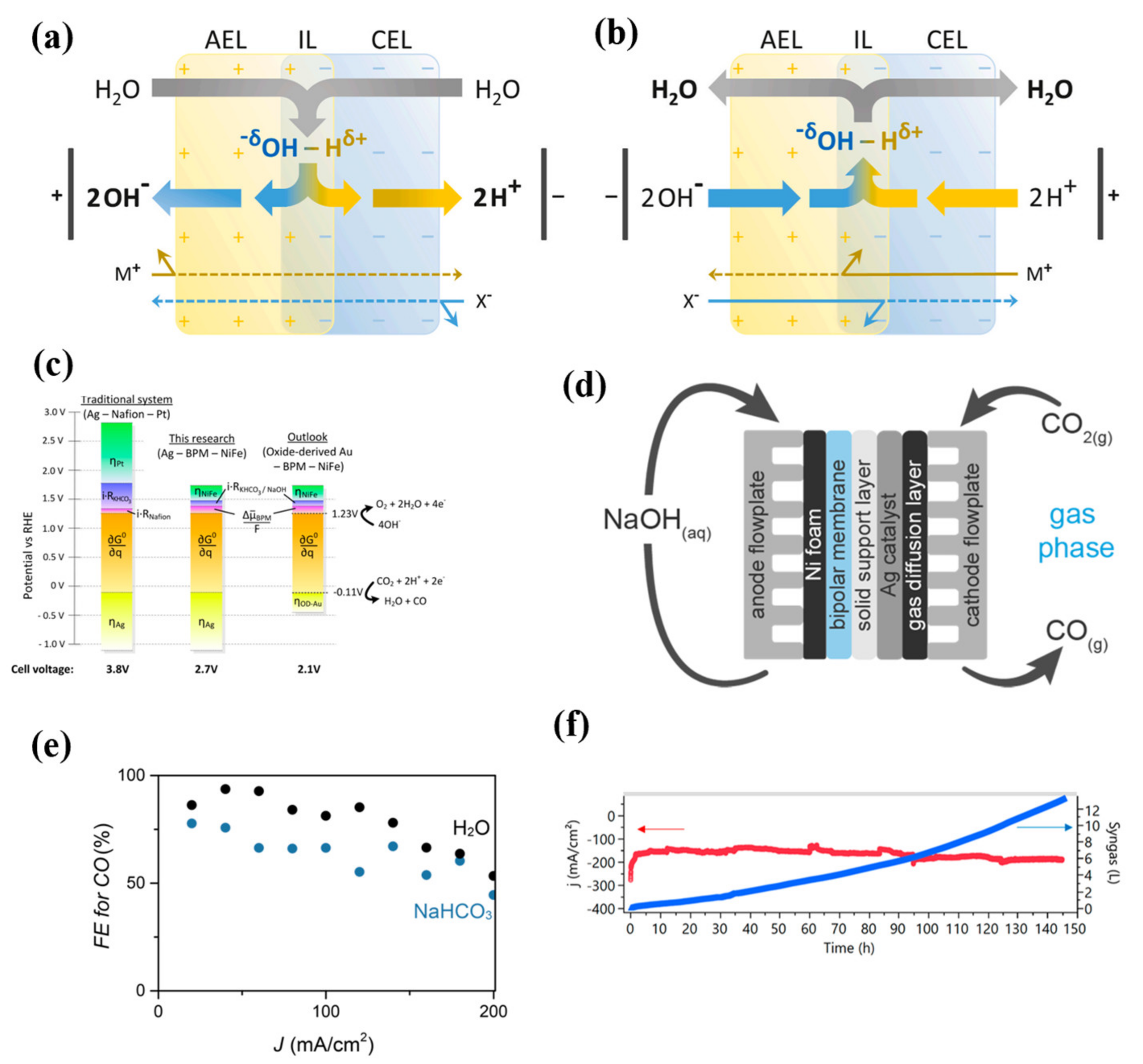
Recently, the bipolar membrane (BPM) has drawn interest from scholars owing to its distinguished properties that AEM and CEM lack. BPM is one kind of polymer membrane consisting of two layers (Figure 8a,b) with thoroughly reversed properties. One side is the AEM while the opposite is the CEM. The junction of the two layers is called as interfacial layer (IL). Unlike traditional monopolar membrane for ions passage, BMP does not allow ions to cross but generates OH and H+ at the IL and toward each side. Generally, the BPM is operated at a reverse bias in a MEA for ECO2RR, the AEM orients the anode and the CEM faces the cathode. The initially reported BPM application ECO2RR by Vermaas et al. [80] and Li et al. [81] did offer some clues in this field. With continuous water dissociation at the IL, the consumed OH and H+ at the anodic electrolyte and the cathodic electrolyte were swiftly fed, developing a long-term local pH. This advantage made a chance for cheaper catalyst for OER replacing the ordinary IrO2. For example, David A. Vermaas et al. [80] prepared a NiFe-hydroxide catalyst to take the place of IrO2, and coupled with the manipulation of electrolyte, the overpotential at the oxygen evolution side was reduced by more than 1 V in a MEA configuration comprising traditional monopolar membrane with Ag-Nafion membrane-Pt system (Figure 8c). In addition to that, by modification of a MEA with a solid-supported aqueous layer between the ECO2RR catalyst and the BPM (Figure 8d), the FE for CO production in the bicarbonate-free system proportionated to at all current density values up to 200 mA/cm2 to a system with NaHCO3 as the electrolyte (Figure 8e) [82]. Moreover, in the late studies of Li et al.’s [83] work, a long-term operation of 145 h also demonstrated BPM insert as a promising tactic (Figure 8f).
However, the earlier advantages of BPM do not mean BPM is perfect in ECO2RR, the energy consumption is the biggest issue for BPM application. This energy cost can be derived from the Nernst equation as Equation (16) shows:
ΔU = 2.3 × RT × ΔpH/F
where ΔU (V) is the voltage drop of the BPM; R (8.314 J/(mol·K)) is the ideal gas constant; T (K) is the temperature; and F (96,485 C/mol) is the Faraday constant. At a given pH difference of 14 (i.e., 1 M fully dissociate slat), the minimum voltage drop is 0.828 V at 298 K. Furthermore, accompanied with the non-ideal condition of BPM, the required voltage often surpasses 0.828 V in a great degree [84].

3. The Significance of pH, Anion, and Cation

The membrane in AEM acts as a good separator avoiding interferences between the anodic and cathodic side, this is mainly because the superior selectivity toward anions/cations stabilizes the reaction environment. Hence, the reaction environment significantly matters in controlling ECO2RR in AEM. Current studies are concentrating on pH, anion, and cation, and their relations are not straightforward because of intertwining effects. This section will focus on revealing a general idea of these three factors’ influences on ECO2RR.

3.1. The Effects of pH

The first imperative before starting this section is making it clear what the local pH is vs. the bulk pH. Local pH refers to the pH at a micro-scale vicinity surrounding the catalyst’s surface and it usually presents in a gradient form due to the depletion of protons. Bulk pH is the real pH in the bulk electrolyte far from the catalyst’s surface. In a traditional H-type cell configuration, local pH is more important than bulk pH toward ECO2RR due to the limited mass transfer efficiency crossing a long distance. Recent studies on pH are mainly concerned with H-type cell configuration, few reviews address MEA. Despite disparities of pH on ECO2RR between these two configurations, some commonalities can be summarized and applied for MEA configuration. We will discuss the pH effect in a H-type cell context, and further deduce or summarize it in the MEA context.
pH significantly matters in ECO2RR performance and product selectivity, especially for cases involving Cu-based catalysts, which are demonstrated as the single metal to produce C2+ ECO2RR products. The formation of CH4 was a pH-sensitive process, whereas the formation of C2H4 was not [71,74]. Stephanie Nitopi [4] summarized previous studies of ECO2RR on Cu-based catalyst spanning pH 6.0–12.2, and they also summarized the data in a Tafel plot as presented in Figure 9a. Generally, partial current density for C2H4 was more likely to vary with onset potential variation rather than with pH variation (Figure 9a). However, the scattered data seen in Figure 9a show that partial current density for CH4 was more dependent on pH variation. Later, with the help of DFT calculations, some clues on the products’ formation pathway disclosed why the differences existed. These two products did not share the same or a similar formation pathway. For CH4, its primary formation pathway took place at the Cu (111) facet via CO protonation with high overpotential. By contrast, C2H2 was more likely to form at the Cu (100) facet via 2 *CO or a *CHO and *CO with low overpotential [71]. The transformation of various feedstocks at the Cu (111) facet usually involved proton transfer, which determined a considerable impact on pH. However, it differed at the Cu (100) facet which was not involved in proton transfer, showing that C2H4 is independent of pH [4,71]. Regarding this, Recep Kas and co-worker [85] took the advantage of the difference of pH dependence to tune local pH at the catalyst’s surface, toward a selective formation of C2H4 with 44% FE while a mere 2% FE to CH4. Furthermore, because C2H2 formation pathway is a pH-insensitive one, overpotential for C2+ can be considerably cut upon RHE scale. This factor allows an alkaline as the electrolyte, which powerfully restricted the formation of CH4 and H2—their formation is a pH-sensitive process. As a result, alkaline electrolyte is becoming a topic in ECO2RR to C2H4 research [86,87]. Furthermore, with numerous investigations into the ECO2RR field, nearly all ECO2RR products suit this pH-dependent rule that the formation of C1 is pH sensitive, whereas the formation of C2+ is not pH-dependent. However, alkaline electrolyte does always benefit ECO2RR to C2+, because high pH leads to the escape of CO2, so the mass transfer efficiency significantly suffers. Moreover, high pH causes an equilibrium toward forming bicarbonate and carbonate as Equations (17) and (18) show. Therefore, it appears impossible to conduct ECO2RR in an alkaline electrolyte. MEA configuration, however, avoids the inherent shortage of a traditional H-type cell. Vapor-fed CO2 in a MEA configuration directly contacts the cathode, avoiding any unnecessary touch with the electrolyte, which drastically strengthens mass transfer efficiency. For instance, Christine M. Gabardo et al. [13] used KOH as an electrolyte for ECO2RR; they obtained >40% FE for C2H4 at 150 mA/cm2, while CH4 got nearly 0% FE, but the instability of cell voltage, pH, and conductivity frustrated their further investigation in this work, which was mainly as a result of the inescapable reaction of CO2 molecules and KOH. Therefore, studying an alkaline electrolyte for ECO2RR in MEA configuration remains a challenge.
CO2 (aqueous) + OH ↔ HCO3
HCO3 + OH ↔ CO32−
In addition to the effect of pH on selectivity toward C1 or C2+ products, pH-affecting selectivity to CO is also important, since highly pure CO is of great interest. Ag and Au are the most concerned metals in the investigation of pH effect on ECO2RR to CO, other metallic or non-metallic catalysts are not widely considered for pH effect exploration. A common view supports that Ag-based catalysts are pH-sensitive. Byoungsu Kim et al. [88] found they are more desirable FE for CO in alkaline environment rather than in acidic or neutral environment. More broadly, the effect of pH is not simply due to the kind of electrolyte; current density and temperature also affect pH in a direct or indirect way, and then ECO2RR performance alters. Zhang and co-workers [89] reported that high current density or high temperature resulted in an increase in local pH in a MEA configuration with Ag foam as the catalyst layer, and the increase in local pH efficiently suppressed HER yet lifted CO formation performance. Unlike ECO2RR on Ag-based catalyst, ECO2RR on Au-based catalyst seems to be independent of pH. One opinion argues that the rate-limiting step on Au-based catalysts is not involved in proton transfer, but the adsorption of CO2 adsorption and formation of *CO2 serve as the rate-limiting step [90,91]. However, a contradictory picture emerges that the better performance by Au-based catalyst can be partly attributed to the higher pH near the electrode’s surface. Plus, high pH also results in the selectivity toward methanol or formate to a certain degree [87]. The effect of pH on ECO2RR on Au-based catalysts still needs further investigation. However, recent reports have found that pH matters while mass transfer efficiency is more important either on Ag-based or Au-based catalysts. A work by Kim et al. [88] revealed that the influence of CO2 concentration was starker than that of pH on ECO2RR to CO on Ag surface. A good performance of Au in ECO2RR to CO was considered as the adsorption infinity between of Au and CO2. Regarding this, utilizing Au as a modifier on catalysts can obviously enhance ECO2RR to CO performance [48,87,90,91].
HER is a pH-dependent process and the major competing side effect, which must be suppressed to maintain the ECO2RR performance. In an acidic environment, proton-to-H2 dominates in ECO2RR, thus no reports on acidic electrolyte have been widely issued. Although at a higher pH, HER is implicitly viable on the RHE scale irrespective of the pH is from the thermodynamics standpoint, HER is abruptly minimized because of kinetic unviability. For example, Gattrell et al. [92] found that high pH shifted equilibrium toward a more negative value for HER (as Figure 9b shows), resulting in a great deceleration for HER. Furthermore, the main H2 formation pathway via proton-to-H2 at low pH gradually becomes water-to-H2 with the increase of pH [4,87]. H2O reduction to H2 is also kinetically unviable and it shows no preferences to pH dependence. In a short summary, alkaline media favors ECO2RR performance rather than HER, but the pH should be controlled in some degree out of the high pH-resulted CO2 escape.
Figure 9. Effects of pH, anion, and cation on ECO2RR performance. (a) is the Tafel plot of the partial current density toward C2H4 and CH4 [4]. Reprinted with permission from Ref. [4]. 2019, American Chemical Society. (b) is the hydrogen evolution polarization data at Cu under different pH [92]. Reprinted with permission from Ref. [92]. 2006, Elsevier. (c) shows the effect of cationic species on ECO2RR performance of various products at Cu surface [93]. Reprinted with permission from Ref. [93]. 1991, The Chemical Society of Japan. (d) shows the effect of anionic species on ECO2RR performance of various products at Cu surface [94]. Reprinted with permission from Ref. [94]. 1989, Royal Society of Chemistry. (e) reflects the influences of Cl, Br and I on ECO2RR with Cu as an electrode [95]. Reprinted with permission from Ref. [95]. 2016, American Chemical Society.
Sustainability 14 05579 g009

3.2. The Effect of Cation

Several works have proven that alkali metal cation exerts on ECO2RR product selectivity and activity. Early work [93,94] revealed that Li+ shared high FE for H2 on Cu catalyst, while Na+, K+, and Cs+ did not (as Figure 9c shows). They put forward a hypothesis that larger cation size-caused larger hydrated radius was more liable to be adsorbed onto the catalyst’s surface, resulting in change of the Outer Helmholtz Plane (OPH) potential. Surrounding protons concentration was also subject to the change of OPH potential due to electrostatic repulsion and attraction between them. Consequently, a preference to hydrocarbons or H2 was observed. It cannot, however, explain why FE for H2 was higher in Cs+-contained electrolyte than in Na+-contained or K+-contained electrolyte. With the deepening of this research, a standpoint argues that the stabilization effect of the cation served as a potential explanation for this confused phenomenon [96,97]. In their theory, K+ exhibits a higher preference to be adsorbed by the Au surface than other cations, then the adsorbed K+ acts as a good specific stabilizer for important intermediates (OCCOH, *CO, etc.). Additionally, K+-created electrostatic field stabilization minimizes the adsorption energy for *CO2, a precursor for C2+, so the ECO2RR to C2+ performance improves. This phenomenon was observed on the Ag and Sn surface, yet not on the Cu surface. In addition, Cs+ and Rb+ whose hydrated radii are larger than that of K+ showed little stabilization effect on intermediates. Resasco et al. [98] proposed another explanation that the cation effect can cause a stronger electrostatic interaction between water molecule surrounding the hydrated cation and negatively charged catalyst. This strengthening will lead to a decline in pKa of hydrolysis of the catalyst’s surface, and an increase of water dissociation due to polarization of O–H bounds of water molecule. The combination of these two effects ultimately results in proton concentration increase at the catalyst’s surface, benefiting more CO2 dissolved near the catalyst and CO2 mass transfer efficiency, therefore improving the performance.

3.3. The Effect of Anion

Similar to cations, the anion also exerts on ECO2RR selectivity and activity. Considering the buffering ability which stabilizes cell operation condition, KHCO3 is the most widely used electrolyte. However, this does not mean that KHCO3 is the optimal electrolyte. Contemporary concerns are concentrated on two major fronts, one is on the halide anion while the other is on the buffering/non-buffering anion.
Varela et al. [95] compared the influences of Cl, Br, and I on ECO2RR with Cu as an electrode. Their reports found that a higher CO selectivity and a lower CH4 and H2 selectivity when Cl and Br worked as the electrolyte anion. However, the ECO2RR product selectivity told an opposite story when I worked as the electrolyte anion (Figure 9e). They concluded two possible reasons for this observation. The first was the morphology change of Cu surface via redox reactions, which can change Cu surface charge when coupled with specific adsorbed halide anions. The other is the covalent interaction between Cu surface and halide anions, which benefited the mass transfer efficiency of CO2 molecules. Huang et al. [99], instead, concluded a distinct result contrast to Ana Sofia Varela et al. [95] work. In their work, situ Raman spectroscopy method revealed that halide anions impacted the surface-bound CO. The I-contained electrolyte displayed the strongest effect and presented the highest increase in selectivity toward C2+. Hence, definite evidence remains a challenge.
The other front is the investigation in different effects of buffering/non-buffering anion on ECO2RR selectivity and activity. Several works reported that Cl, SO42−, etc. anion showed little impact on ECO2RR toward CO, C2H4, formate, and alcohol on Cu surface and their presence also suppressed the CH4 and H2 formation. This is mainly because these anions with little buffering can facilitate a growth in local pH, thus CH4 and H2 formation was suppressed. However, in the case of HCO3 and HPO42−, FE for ECO2RR to CH4 and H2 increased versus cases of low buffering electrolyte. Even in the case of higher concentration of HCO3 and HPO42−, which possessed a greater buffering, CH4 and H2 formation improvement remain [100]. Fortunately, this undesirable tendency was negligible in a MEA configuration [13]. In general, anion with low buffering favors ECO2RR toward CO and other hydrocarbons while suppressing CH4 and H2 formation, yet anion with high buffering tells an adverse story.

4. Microfluidic Flow Cells

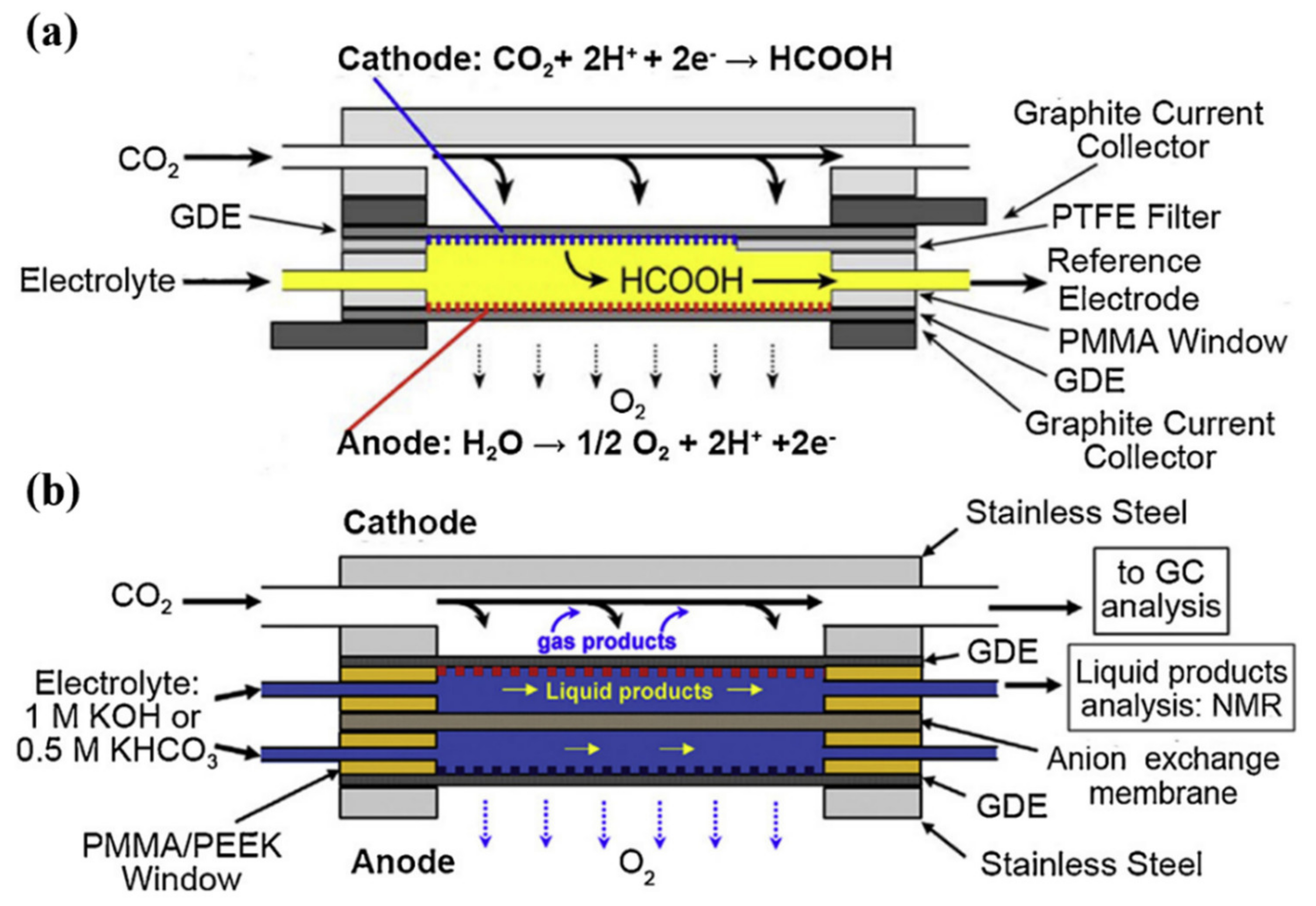
A recent advancement in MEA configuration is the microfluidic flow cell. The first reported one was by Whipple et al. [101] who used a microfluidic flow cell to produce formate. The spotlight of this configuration is the membrane-free system while with an ultrathin electrolyte layer between cathode and anode (Figure 10a). However, a GDE was still equipped to separate gas and liquid phase. This flow cell was of good adaptability to changeable operation conditions and performed well in minimizing water management problems. After that, the same configuration was applied for ECO2RR to CO with 90% plus FE at 101 mA/cm2 [102]. Noticeably, due to the ultrathin interlayer for KOH electrolyte flowing, mass transfer efficiency of CO2 enhanced without much fluctuation in pH. Moving forward in this configuration, a membrane-contained microfluidic flow cell (Figure 10b) was proposed subsequently [103]. This modified configuration allowed for simultaneous gaseous and liquid product collection. A desirable result was achieved by this configuration with 46% FE for C2H4 and ethanol while at a commercially favored current density of 200 mA/cm2. Later, Dinh et al. [42] scored a record high in ~70% FE for C2H4 at 470 mA/cm2 using this membrane-contained microfluidic flow cell. Despite a few of reports on microfluidic flow cell for ECO2RR, it is well believed that this configuration deserves a good consideration in next stage of this field.

5. Summary and Outlook

Dependency upon fossil fuel has caused tremendous CO2 emission into the atmosphere in a way which surpasses CO2 natural recycling. The result is the break of the carbon loop and global warming, triggering numerous tragedies striking humankind. These issues demand a potent method to transform CO2 in the atmosphere into a form that is stable and has no effect on the global climate. ECO2RR is a useful means to transform CO2 into value-added products. Coupled with a renewable energy source, ECO2RR fits well into this context. Regarding this, how to drive ECO2RR to be economically and technically viable is of high profile. In this review, we presented an overview of a compacted and potent MEA configuration for ECO2RR. We highlighted the structure, principle, operating conditions, and state-of-the-art advances in this configuration. Despite many steps having been achieved in MEA for ECO2RR, many fronts still require deepening study and development. We generalized them into three items as follows.
High performance of ECO2RR in MEA is a constant topic in an economy-oriented context. Recent advances in CO2 to CO hit a record high with nearly 100% FE, but CO2 to C2+ suffered an inferior performance. Moreover, an economically viable configuration should be operated at a high current density (>200 mA/cm2) and a long-time (>8000 h). Up to now, MEA reaches high current density (the largest record is 1 A/cm2, a summary in Table 2), but can only be operated over several hundred hours. Compounding this issue, energy transfer efficiency for ECO2RR to C2+ is far below 60–70%, a profitable figure for ECO2RR application. Therefore, improvement in ECO2RR performance may require advance in these two fronts, and they can be solved via configuration optimization, operating condition control, etc.
The second is the selectivity of products and products refinement. Except for CO and formate, few reports on a highly pure form of a single ECO2RR product have been presented. Despite MEA configuration having an advantage on ECO2RR product production over HER, the products remain complex with combination of several C1 and C2+. A Cu-based catalyst is the single metal to produce C2+, but its selectivity to a pure product is not controlled due to complicated formation procedure. Purification also matters, the mixture of several liquid or gaseous products overshadows ECO2RR application because of the high cost of product separation. Wang’s group utilized a solid electrolyte to efficiently collect formate, which efficiently separated the liquid and gaseous product. This strategy provides a good example of liquid product production and collection. However, only pure liquid product is profitable, thus auger in catalyst development is the first imperative.
The third is the characterization method. Current characterization tools are suitable to observe ECO2RR in H-type cell, whereas they are not suitable to observe ECO2RR in MEA configuration. In situ characterization methods play a big role in understanding behaviors of ECO2RR in MEA configuration. Fortunately, with efforts of some scholars, the customized cell was feasible for operando spectroscopy characterization such as infrared and Raman. Strategies may also benefit from studies in fuel cells, since the most widely used application of MEA configuration is concentrated on fuel cells. For example, X-ray tomography has already been employed in detecting the catalyst degradation process, which is of great importance in understanding the durability of catalysts and provides some clues to design durable catalysts. The latest research also reported using laser scanning confocal microscopy to understand how the wettability of the C/Au interface influences ECO2RR to CO, which also introduces a new means to study ECO2RR in MEA.
In summary, with continued efforts and development, ECO2RR in MEA configuration has made great progress. Challenges remains; however, opportunities are also coupled with it, and it is firmly believed that introducing new ideas and efforts poured into this field, electrochemical ECO2RR to value-added product will consequently become competitive in ecotechnology.

Funding

The work is financially supported by the National Key R&D Program of China (No. 2019YFD1100203), Key R&D Plan of Anhui Province (No. 202104g01020010), and Gansu Livelihood Science and Technology Project-Special Topic of Social Development (No. 18CX3FA001).

Institutional Review Board Statement

Not applicable.

Informed Consent Statement

This paper does not involve humans.

Data Availability Statement

No data supported results were created in this paper.

Conflicts of Interest

The authors declare no conflict of interest.

References

  1. Cavicchioli, R.; Ripple, W.J.; Timmis, K.N.; Azam, F.; Bakken, L.R.; Baylis, M.; Behrenfeld, M.J.; Boetius, A.; Boyd, P.W.; Classen, A.T.; et al. Webster, Scientists’ warning to humanity: Microorganisms and climate change. Nat. Rev. Microbiol. 2019, 17, 569–586. [Google Scholar] [CrossRef] [PubMed] [Green Version]
  2. Yalew, S.G.; van Vliet, M.T.H.; Gernaat, D.E.H.J.; Ludwig, F.; Miara, A.; Park, C.; Byers, E.; de Cian, E.; Piontek, F.; Iyer, G.; et al. Impacts of climate change on energy systems in global and regional scenarios. Nat. Energy 2020, 5, 794–802. [Google Scholar] [CrossRef]
  3. Dai, A.; Luo, D.; Song, M.; Liu, J. Arctic amplification is caused by sea-ice loss under increasing CO2. Nat. Commun. 2019, 10, 121. [Google Scholar] [CrossRef] [PubMed] [Green Version]
  4. Nitopi, S.; Bertheussen, E.; Scott, S.B.; Liu, X.; Engstfeld, A.K.; Horch, S.; Seger, B.; Stephens, I.E.L.; Chan, K.; Hahn, C.; et al. Progress and Perspectives of Electrochemical CO2 Reduction on Copper in Aqueous Electrolyte. Chem. Rev. 2019, 119, 7610–7672. [Google Scholar] [CrossRef] [PubMed] [Green Version]
  5. Fan, L.; Xia, C.; Yang, F.; Wang, J.; Wang, H.; Lu, Y. Strategies in catalysts and electrolyzer design for electrochemical CO2 reduction toward C2+ products. Sci. Adv. 2020, 6, 910–918. [Google Scholar] [CrossRef] [Green Version]
  6. Weekes, D.M.; Salvatore, D.A.; Reyes, A.; Huang, A.; Berlinguette, C.P. Electrolytic CO2 Reduction in a Flow Cell. Acc. Chem. Res. 2018, 51, 910–918. [Google Scholar] [CrossRef]
  7. Liang, S.; Altaf, N.; Huang, L.; Gao, Y.; Wang, Q. Electrolytic cell design for electrochemical CO2 reduction. J. CO2 Util. 2020, 35, 90–105. [Google Scholar] [CrossRef]
  8. Malkhandi, S.; Yeo, B.S. Electrochemical conversion of carbon dioxide to high value chemicals using gas-diffusion electrodes. Curr. Opin. Chem. Eng. 2019, 26, 112–121. [Google Scholar] [CrossRef]
  9. Wilson, I.A.G.; Staffell, I. Rapid fuel switching from coal to natural gas through effective carbon pricing. Nat. Energy 2018, 3, 365–372. [Google Scholar] [CrossRef]
  10. Rumayor, M.; Dominguez-Ramos, A.; Perez, P.; Irabien, A. A techno-economic evaluation approach to the electrochemical reduction of CO2 for formic acid manufacture. J. CO2 Util. 2019, 34, 490–499. [Google Scholar] [CrossRef]
  11. Jouny, M.; Luc, W.; Jiao, F. General Techno-Economic Analysis of CO2 Electrolysis Systems. Ind. Eng. Chem. Res. 2018, 57, 2165–2177. [Google Scholar] [CrossRef]
  12. Kim, D.; Kley, C.S.; Li, Y.; Yang, P. Copper nanoparticle ensembles for selective electroreduction of CO2 to C2–C3 products. Proc. Natl. Acad. Sci. USA 2017, 114, 10560–10565. [Google Scholar] [CrossRef] [Green Version]
  13. Gabardo, C.M.; O’Brien, C.P.; Edwards, J.P.; McCallum, C.; Xu, Y.; Dinh, C.T.; Li, J.; Sargent, E.H.; Sinton, D. Continuous Carbon Dioxide Electroreduction to Concentrated Multi-carbon Products Using a Membrane Electrode Assembly. Joule 2019, 3, 2777–2791. [Google Scholar] [CrossRef]
  14. Kim, T.; Palmore, G.T.R. A scalable method for preparing Cu electrocatalysts that convert CO2 into C2+ products. Nat. Commun. 2020, 11, 3622. [Google Scholar] [CrossRef]
  15. Zhu, Q.; Sun, X.; Yang, D.; Ma, J.; Kang, X.; Zheng, L.; Zhang, J.; Wu, Z.; Han, B. Carbon dioxide electroreduction to C2 products over copper-cuprous oxide derived from electrosynthesized copper complex. Nat. Commun. 2019, 10, 3851. [Google Scholar] [CrossRef] [PubMed] [Green Version]
  16. Guo, W.; Shim, K.; Ngome, F.O.O.; Moon, Y.H.; Choi, S.Y.; Kim, Y.T. Highly active coral-like porous silver for electrochemical reduction of CO2to CO. J. CO2 Util. 2020, 41, 101242. [Google Scholar] [CrossRef]
  17. Gao, Y.; Wu, Q.; Liang, X.; Wang, Z.; Zheng, Z.; Wang, P.; Liu, Y.; Dai, Y.; Whangbo, M.H.; Huang, B. Cu2O Nanoparticles with Both {100} and {111} Facets for Enhancing the Selectivity and Activity of CO2 Electroreduction to Ethylene. Adv. Sci. 2020, 7, 1902820. [Google Scholar] [CrossRef] [PubMed] [Green Version]
  18. Nguyen, T.N.; Dinh, C.-T. Gas diffusion electrode design for electrochemical carbon dioxide reduction. Chem. Soc. Rev. 2020, 49, 7488–7504. [Google Scholar] [CrossRef]
  19. Zhao, C.; Wang, J. Electrochemical reduction of CO2 to formate in aqueous solution using electro-deposited Sn catalysts. Chem. Eng. J. 2016, 293, 161–170. [Google Scholar] [CrossRef]
  20. Verma, S.; Kim, B.; Jhong, H.R.M.; Ma, S.; Kenis, P.J.A. A gross-margin model for defining technoeconomic benchmarks in the electroreduction of CO2. ChemSusChem 2016, 9, 1972–1979. [Google Scholar] [CrossRef]
  21. Burdyny, T.; Smith, W.A. CO2 reduction on gas-diffusion electrodes and why catalytic performance must be assessed at commercially-relevant conditions. Energy Environ. Sci. 2019, 12, 1442–1453. [Google Scholar] [CrossRef] [Green Version]
  22. Bhosale, A.C.; Ghosh, P.C.; Assaud, L. Preparation methods of membrane electrode assemblies for proton exchange membrane fuel cells and unitized regenerative fuel cells: A review. Renew. Sustain. Energy Rev. 2020, 133, 110286. [Google Scholar] [CrossRef]
  23. Higgins, D.; Hahn, C.; Xiang, C.; Jaramillo, T.F.; Weber, A.Z. Gas-Diffusion Electrodes for Carbon Dioxide Reduction: A New Paradigm. ACS Energy Lett. 2019, 4, 317–324. [Google Scholar] [CrossRef] [Green Version]
  24. Zheng, T.; Jiang, K.; Ta, N.; Hu, Y.; Zeng, J.; Liu, J.; Wang, H. Large-Scale and Highly Selective CO2 Electrocatalytic Reduction on Nickel Single-Atom Catalyst. Joule 2019, 3, 265–278. [Google Scholar] [CrossRef] [Green Version]
  25. Jeong, H.Y.; Balamurugan, M.; Choutipalli, V.S.K.; Jeong, E.S.; Subramanian, V.; Sim, U.; Nam, K.T. Achieving highly efficient CO2 to CO electroreduction exceeding 300 mA cm−2 with single-atom nickel electrocatalysts. J. Mater. Chem. A 2019, 7, 10651–10661. [Google Scholar] [CrossRef]
  26. Li, F.; Thevenon, A.; Rosas-Hernández, A.; Wang, Z.; Li, Y.; Gabardo, C.M.; Ozden, A.; Dinh, C.T.; Li, J.; Wang, Y.; et al. Molecular tuning of CO2-to-ethylene conversion. Nature 2020, 577, 509–513. [Google Scholar] [CrossRef] [PubMed] [Green Version]
  27. De Arquer, F.P.G.; Dinh, C.T.; Ozden, A.; Wicks, J.; McCallum, C.; Kirmani, A.R.; Nam, D.H.; Gabardo, C.; Seifitokaldani, A.; Wang, X.; et al. CO2 electrolysis to multicarbon products at activities greater than 1 A cm−2. Science 2020, 367, 661–666. [Google Scholar] [CrossRef] [PubMed]
  28. She, X.; Zhang, T.; Li, Z.; Li, H.; Xu, H.; Wu, J. Tandem Electrodes for Carbon Dioxide Reduction into C2+ Products at Simultaneously High Production Efficiency and Rate. Cell Rep. Phys. Sci. 2020, 1, 100051. [Google Scholar] [CrossRef]
  29. Zamel, N.; Li, X.; Shen, J. Correlation for the effective gas diffusion coefficient in carbon paper diffusion media. Energy Fuels 2009, 23, 6070–6078. [Google Scholar] [CrossRef] [Green Version]
  30. Ozden, A.; Shahgaldi, S.; Li, X.; Hamdullahpur, F. A review of gas diffusion layers for proton exchange membrane fuel cells—With a focus on characteristics, characterization techniques, materials and designs. Prog. Energy Combust. Sci. 2019, 74, 50–102. [Google Scholar] [CrossRef]
  31. Lapicque, F.; Belhadj, M.; Bonnet, C.; Pauchet, J.; Thomas, Y. A critical review on gas diffusion micro and macroporous layers degradations for improved membrane fuel cell durability. J. Power Sources 2016, 336, 40–53. [Google Scholar] [CrossRef]
  32. Morgan, J.M.; Datta, R. Understanding the gas diffusion layer in proton exchange membrane fuel cells. I. How its structural characteristics affect diffusion and performance. J. Power Sources 2014, 251, 269–278. [Google Scholar] [CrossRef]
  33. Yi, G.; Cai, Z.; Gao, Z.; Jiang, Z.; Huang, X.; Derksen, J.J. Droplet impingement and wetting behavior on a chemically heterogeneous surface in the Beyond–Cassie–Baxter regime. AIChE J. 2020, 66, 66. [Google Scholar] [CrossRef]
  34. Velayutham, G.; Kaushik, J.; Rajalakshmi, N.; Dhathathreyan, K.S. Effect of PTFE content in gas diffusion media and microlayer on the performance of PEMFC tested under ambient pressure. Fuel Cells 2007, 7, 314–318. [Google Scholar] [CrossRef]
  35. Tsai, J.C.; Lin, C.K. Effect of PTFE content in gas diffusion layer based on Nafion®/PTFE membrane for low humidity proton exchange membrane fuel cell. J. Taiwan Inst. Chem. Eng. 2011, 42, 945–951. [Google Scholar] [CrossRef]
  36. Becker, J.; Wieser, C.; Fell, S.; Steiner, K. A multi-scale approach to material modeling of fuel cell diffusion media. Int. J. Heat Mass Transf. 2011, 54, 1360–1368. [Google Scholar] [CrossRef]
  37. Hiesgen, R.; Wehl, I.; Friedrich, K.A.; Schulze, M.; Haug, A.; Bauder, A.; Carreras, A.; Yuan, X.-Z.; Wang, H. Atomic Force Microscopy Investigation of Polymer Fuel Cell Gas Diffusion Layers before and after Operation. ECS Trans. 2019, 28, 79–84. [Google Scholar] [CrossRef]
  38. Song, S.; Zhang, H.; Ma, X.; Shao, Z.G.; Zhang, Y.; Yi, B. Bifunctional oxygen electrode with corrosion-resistive gas diffusion layer for unitized regenerative fuel cell. Electrochem. Commun. 2006, 8, 399–405. [Google Scholar] [CrossRef]
  39. Ozden, A.; Shahgaldi, S.; Zhao, J.; Li, X.; Hamdullahpur, F. Assessment of graphene as an alternative microporous layer material for proton exchange membrane fuel cells. Fuel 2018, 215, 726–734. [Google Scholar] [CrossRef]
  40. Ferreira, R.B.; Falcão, D.S.; Oliveira, V.B.; Pinto, A.M.F.R. Experimental study on the membrane electrode assembly of a proton exchange membrane fuel cell: Effects of microporous layer, membrane thickness and gas diffusion layer hydrophobic treatment. Electrochim. Acta 2017, 224, 337–345. [Google Scholar] [CrossRef]
  41. Orogbemi, O.M.; Ingham, D.B.; Ismail, M.S.; Hughes, K.J.; Ma, L.; Pourkashanian, M. The effects of the composition of microporous layers on the permeability of gas diffusion layers used in polymer electrolyte fuel cells. Int. J. Hydrogen Energy 2016, 41, 21345–21351. [Google Scholar] [CrossRef]
  42. Dinh, C.T.; Burdyny, T.; Kibria, G.; Seifitokaldani, A.; Gabardo, C.M.; de Arquer, F.P.G.; Kiani, A.; Edwards, J.P.; de Luna, P.; Bushuyev, O.S.; et al. CO2 electroreduction to ethylene via hydroxide-mediated copper catalysis at an abrupt interface. Science 2018, 360, 783–787. [Google Scholar] [CrossRef] [PubMed] [Green Version]
  43. Park, G.G.; Sohn, Y.J.; Yim, S.D.; Yang, T.H.; Yoon, Y.G.; Lee, W.Y.; Kim, C.S. Influence of water behavior in the gas diffusion layer on the performance of PEMFC. Fuel Cell Sci. Eng. Technol. 2004, 2004, 1–5. [Google Scholar] [CrossRef]
  44. Jeon, D.H. Effect of gas diffusion layer thickness on liquid water transport characteristics in polymer electrolyte membrane fuel cells. J. Power Sources 2020, 475, 228578. [Google Scholar] [CrossRef]
  45. Gao, Y.; Montana, A.; Chen, F. Evaluation of porosity and thickness on effective diffusivity in gas diffusion layer. J. Power Sources 2017, 342, 252–265. [Google Scholar] [CrossRef]
  46. Bagger, A.; Ju, W.; Varela, A.S.; Strasser, P.; Rossmeisl, J. Electrochemical CO2 Reduction: A Classification Problem. ChemPhysChem 2017, 18, 3266–3273. [Google Scholar] [CrossRef] [Green Version]
  47. Yadav, D.K.; Singh, D.K.; Ganesan, V. Recent strategy(ies) for the electrocatalytic reduction of CO2: Ni single-atom catalysts for the selective electrochemical formation of CO in aqueous electrolytes. Curr. Opin. Electrochem. 2020, 22, 87–93. [Google Scholar] [CrossRef]
  48. Yang, D.R.; Liu, L.; Zhang, Q.; Shi, Y.; Zhou, Y.; Liu, C.; Wang, F.B.; Xia, X.H. Importance of Au nanostructures in CO2 electrochemical reduction reaction. Sci. Bull. 2020, 65, 796–802. [Google Scholar] [CrossRef]
  49. Liu, J.; Wang, Y.; Jiang, H.; Jiang, H.; Zhou, X.; Li, Y.; Li, C. Ag@Au Core-Shell Nanowires for Nearly 100 % CO2-to-CO Electroreduction. Chem.-Asian J. 2020, 15, 425–431. [Google Scholar] [CrossRef]
  50. Luo, W.; Zhang, Q.; Zhang, J.; Moioli, E.; Zhao, K.; Züttel, A. Electrochemical reconstruction of ZnO for selective reduction of CO2 to CO. Appl. Catal. B Environ. 2020, 273, 119060. [Google Scholar] [CrossRef]
  51. Guo, W.; Shim, K.; Kim, Y.T. Ag layer deposited on Zn by physical vapor deposition with enhanced CO selectivity for electrochemical CO2 reduction. Appl. Surf. Sci. 2020, 526, 146651. [Google Scholar] [CrossRef]
  52. Ma, Z.; Wu, D.; Han, X.; Wang, H.; Zhang, L.; Gao, Z.; Xu, F.; Jiang, K. Ultrasonic assisted synthesis of Zn-Ni bi-metal MOFs for interconnected Ni-N-C materials with enhanced electrochemical reduction of CO2. J. CO2 Util. 2019, 32, 251–258. [Google Scholar] [CrossRef]
  53. Hou, Y.; Liang, Y.L.; Shi, P.C.; Huang, Y.B.; Cao, R. Atomically dispersed Ni species on N-doped carbon nanotubes for electroreduction of CO2 with nearly 100% CO selectivity. Appl. Catal. B Environ. 2020, 271, 118929. [Google Scholar] [CrossRef]
  54. Cheng, Y.; Zhao, S.; Li, H.; He, S.; Veder, J.P.; Johannessen, B.; Xiao, J.; Lu, S.; Pan, J.; Chisholm, M.F.; et al. Unsaturated edge-anchored Ni single atoms on porous microwave exfoliated graphene oxide for electrochemical CO2. Appl. Catal. B Environ. 2019, 243, 294–303. [Google Scholar] [CrossRef]
  55. Li, L.; Huang, Y.; Li, Y. Carbonaceous materials for electrochemical CO2 reduction. EnergyChem 2020, 2, 100024. [Google Scholar] [CrossRef]
  56. Ding, P.; Zhao, H.; Li, T.; Luo, Y.; Fan, G.; Chen, G.; Gao, S.; Shi, X.; Lu, S.; Sun, X. Metal-based electrocatalytic conversion of CO2 to formic acid/formate. J. Mater. Chem. A 2020, 8, 21947–21960. [Google Scholar] [CrossRef]
  57. Kortlever, R.; Shen, J.; Schouten, K.J.P.; Calle-Vallejo, F.; Koper, M.T.M. Catalysts and Reaction Pathways for the Electrochemical Reduction of Carbon Dioxide. J. Phys. Chem. Lett. 2015, 6, 4073–4082. [Google Scholar] [CrossRef] [PubMed]
  58. Philips, M.F.; Gruter, G.-J.M.; Koper, M.T.M.; Schouten, K.J.P. Optimizing the Electrochemical Reduction of CO2 to Formate: A State-of-the-Art Analysis. ACS Sustain. Chem. Eng. 2020, 8, 15430–15444. [Google Scholar] [CrossRef]
  59. Liu, L.X.; Zhou, Y.; Chang, Y.C.; Zhang, J.R.; Jiang, L.P.; Zhu, W.; Lin, Y. Tuning Sn3O4 for CO2 reduction to formate with ultra-high current density. Nano Energy 2020, 77, 105296. [Google Scholar] [CrossRef]
  60. Sen, S.; Brown, S.M.; Leonard, M.L.; Brushett, F.R. Electroreduction of carbon dioxide to formate at high current densities using tin and tin oxide gas diffusion electrodes. J. Appl. Electrochem. 2019, 49, 917–928. [Google Scholar] [CrossRef]
  61. Del Castillo, A.; Alvarez-Guerra, M.; Solla-Gullón, J.; Sáez, A.; Montiel, V.; Irabien, A. Sn nanoparticles on gas diffusion electrodes: Synthesis, characterization and use for continuous CO2 electroreduction to formate. J. CO2 Util. 2017, 18, 222–228. [Google Scholar] [CrossRef] [Green Version]
  62. De Mot, B.; Hereijgers, J.; Duarte, M.; Breugelmans, T. Influence of flow and pressure distribution inside a gas diffusion electrode on the performance of a flow-by CO2 electrolyzer. Chem. Eng. J. 2019, 378, 122224. [Google Scholar] [CrossRef]
  63. Díaz-Sainz, G.; Alvarez-Guerra, M.; Solla-Gullón, J.; García-Cruz, L.; Montiel, V.; Irabien, A. CO2 electroreduction to formate: Continuous single-pass operation in a filter-press reactor at high current densities using Bi gas diffusion electrodes. J. CO2 Util. 2019, 34, 12–19. [Google Scholar] [CrossRef]
  64. Fan, L.; Xia, C.; Zhu, P.; Lu, Y.; Wang, H. Electrochemical CO2 reduction to high-concentration pure formic acid solutions in an all-solid-state reactor. Nat. Commun. 2020, 11, 3633. [Google Scholar] [CrossRef] [PubMed]
  65. Xia, C.; Zhu, P.; Jiang, Q.; Pan, Y.; Liang, W.; Stavitsk, E.; Alshareef, H.N.; Wang, H. Continuous production of pure liquid fuel solutions via electrocatalytic CO2 reduction using solid-electrolyte devices. Nat. Energy 2019, 4, 776–785. [Google Scholar] [CrossRef]
  66. Zhang, W.; Hu, Y.; Ma, L.; Zhu, G.; Wang, Y.; Xue, X.; Chen, R.; Yang, S.; Jin, Z. Progress and Perspective of Electrocatalytic CO2 Reduction for Renewable Carbonaceous Fuels and Chemicals. Adv. Sci. 2018, 5, 1700275. [Google Scholar] [CrossRef]
  67. Hanselman, S.; Koper, M.T.M.; Calle-Vallejo, F. Computational Comparison of Late Transition Metal (100) Surfaces for the Electrocatalytic Reduction of CO to C2 Species. ACS Energy Lett. 2018, 3, 1062–1067. [Google Scholar] [CrossRef]
  68. Luo, W.; Nie, X.; Janik, M.J.; Asthagiri, A. Facet Dependence of CO2 Reduction Paths on Cu Electrodes. ACS Catal. 2016, 6, 219–229. [Google Scholar] [CrossRef]
  69. Cheng, T.; Xiao, H.; Goddard, W.A. Full atomistic reaction mechanism with kinetics for CO reduction on Cu(100) from ab initio molecular dynamics free-energy calculations at 298 K. Proc. Natl. Acad. Sci. USA 2017, 114, 1795–1800. [Google Scholar] [CrossRef] [Green Version]
  70. Garza, A.J.; Bell, A.T.; Head-Gordon, M. Mechanism of CO2 Reduction at Copper Surfaces: Pathways to C2 Products. ACS Catal. 2018, 8, 1490–1499. [Google Scholar] [CrossRef] [Green Version]
  71. Zheng, Y.; Vasileff, A.; Zhou, X.; Jiao, Y.; Jaroniec, M.; Qiao, S.Z. Understanding the Roadmap for Electrochemical Reduction of CO2 to Multi-Carbon Oxygenates and Hydrocarbons on Copper-Based Catalysts. J. Am. Chem. Soc. 2019, 141, 7646–7659. [Google Scholar] [CrossRef] [PubMed]
  72. Gao, D.; Arán-Ais, R.M.; Jeon, H.S.; Cuenya, B.R. Rational catalyst and electrolyte design for CO2 electroreduction towards multicarbon products. Nat. Catal. 2019, 2, 198–210. [Google Scholar] [CrossRef]
  73. Fan, Q.; Zhang, M.; Jia, M.; Liu, S.; Qiu, J.; Sun, Z. Electrochemical CO2 reduction to C2+ species: Heterogeneous electrocatalysts, reaction pathways, and optimization strategies. Mater. Today Energy 2018, 10, 280–301. [Google Scholar] [CrossRef]
  74. De Gregorio, G.L.; Burdyny, T.; Loiudice, A.; Iyengar, P.; Smith, W.A.; Buonsanti, R. Facet-Dependent Selectivity of Cu Catalysts in Electrochemical CO2 Reduction at Commercially Viable Current Densities. ACS Catal. 2020, 10, 4854–4862. [Google Scholar] [CrossRef] [PubMed] [Green Version]
  75. Yang, H.; Lin, Q.; Zhang, C.; Yu, X.; Cheng, Z.; Li, G.; Hu, Q.; Ren, X.; Zhang, Q.; Liu, J.; et al. Carbon dioxide electroreduction on single-atom nickel decorated carbon membranes with industry compatible current densities. Nat. Commun. 2020, 11, 593. [Google Scholar] [CrossRef] [Green Version]
  76. Ren, S.; Joulié, D.; Salvatore, D.; Torbensen, K.; Wang, M.; Robert, M.; Berlinguette, C.P. Molecular electrocatalysts can mediate fast, selective CO2 reduction in a flow cell. Science 2019, 365, 367–369. [Google Scholar] [CrossRef]
  77. Wang, G.; Pan, J.; Jiang, S.P.; Yang, H. Gas phase electrochemical conversion of humidified CO2 to CO and H2 on proton-exchange and alkaline anion-exchange membrane fuel cell reactors. J. CO2 Util. 2018, 23, 152–158. [Google Scholar] [CrossRef]
  78. Delacourt, C.; Ridgway, P.L.; Kerr, J.B.; Newman, J. Design of an Electrochemical Cell Making Syngas (CO + H2]) from CO2 and H2O Reduction at Room Temperature. J. Electrochem. Soc. 2008, 155, B42. [Google Scholar] [CrossRef]
  79. Unnikrishnan, E.K.; Kumar, S.D.; Maiti, B. Permeation of inorganic anions through Nafion ionomer membrane. J. Memb. Sci. 1997, 137, 133–137. [Google Scholar] [CrossRef]
  80. Vermaas, D.A.; Smith, W.A. Synergistic Electrochemical CO2 Reduction and Water Oxidation with a Bipolar Membrane. ACS Energy Lett. 2016, 1, 1143–1148. [Google Scholar] [CrossRef]
  81. Li, Y.C.; Zhou, D.; Yan, Z.; Gonçalves, R.H.; Salvatore, D.A.; Berlinguette, C.P.; Mallouk, T.E. Electrolysis of CO2 to Syngas in Bipolar Membrane-Based Electrochemical Cells. ACS Energy Lett. 2016, 1, 1149–1153. [Google Scholar] [CrossRef]
  82. Salvatore, D.A.; Weekes, D.M.; He, J.; Dettelbach, K.E.; Li, Y.C.; Mallouk, T.E.; Berlinguette, C.P. Electrolysis of Gaseous CO2 to CO in a Flow Cell with a Bipolar Membrane. ACS Energy Lett. 2018, 3, 149–154. [Google Scholar] [CrossRef]
  83. Li, Y.C.; Lee, G.; Yuan, T.; Wang, Y.; Nam, D.H.; Wang, Z.; de Arquer, F.P.G.; Lum, Y.; Dinh, C.T.; Voznyy, O.; et al. CO2 Electroreduction from Carbonate Electrolyte. ACS Energy Lett. 2019, 4, 1427–1431. [Google Scholar] [CrossRef]
  84. Pärnamäe, R.; Mareev, S.; Nikonenko, V.; Melnikov, S.; Sheldeshov, N.; Zabolotskii, V.; Hamelers, H.V.M.; Tedesco, M. Bipolar membranes: A review on principles, latest developments, and applications. J. Memb. Sci. 2021, 617, 118538. [Google Scholar] [CrossRef]
  85. Kas, R.; Kortlever, R.; Yilmaz, H.; Koper, M.T.M.; Mul, G. Manipulating the Hydrocarbon Selectivity of Copper Nanoparticles in CO2 Electroreduction by Process Conditions. ChemElectroChem 2015, 2, 354–358. [Google Scholar] [CrossRef]
  86. Moura de Salles Pupo, M.; Kortlever, R. Electrolyte Effects on the Electrochemical Reduction of CO2. ChemPhysChem 2019, 20, 2926–2935. [Google Scholar] [CrossRef] [Green Version]
  87. Varela, A.S. The importance of pH in controlling the selectivity of the electrochemical CO2 reduction. Curr. Opin. Green Sustain. Chem. 2020, 26, 100371. [Google Scholar] [CrossRef]
  88. Kim, B.; Ma, S.; Jhong, H.R.M.; Kenis, P.J.A. Influence of dilute feed and pH on electrochemical reduction of CO2 to CO on Ag in a continuous flow electrolyzer. Electrochim. Acta 2015, 166, 271–276. [Google Scholar] [CrossRef] [Green Version]
  89. Zhang, Z.; Melo, L.; Jansonius, R.P.; Habibzadeh, F.; Grant, E.R.; Berlinguette, C.P. pH Matters When Reducing CO2 in an Electrochemical Flow Cell. ACS Energy Lett. 2020, 5, 3101–3107. [Google Scholar] [CrossRef]
  90. Wuttig, A.; Yaguchi, M.; Motobayashi, K.; Osawa, M.; Surendranath, Y. Inhibited proton transfer enhances Au-catalyzed CO2-to-fuels selectivity. Proc. Natl. Acad. Sci. USA 2016, 113, E4585–E4593. [Google Scholar] [CrossRef] [Green Version]
  91. Zhang, B.A.; Ozel, T.; Elias, J.S.; Costentin, C.; Nocera, D.G. Interplay of Homogeneous Reactions, Mass Transport, and Kinetics in Determining Selectivity of the Reduction of CO2 on Gold Electrodes. ACS Cent. Sci. 2019, 5, 1097–1105. [Google Scholar] [CrossRef] [PubMed] [Green Version]
  92. Gattrell, M.; Gupta, N.; Co, A. A review of the aqueous electrochemical reduction of CO2 to hydrocarbons at copper. J. Electroanal. Chem. 2006, 594, 1–19. [Google Scholar] [CrossRef]
  93. Murata, A.; Hori, Y. Product selectivity affected by cationic species in electrochemical reduction of CO2 and CO at a Cu electrode. Bull. Chem. Soc. Jpn. 1991, 64, 123–127. [Google Scholar] [CrossRef] [Green Version]
  94. Hori, Y.; Murata, A.; Takahashi, R. Formation of hydrocarbons in the electrochemical reduction of carbon dioxide at a copper electrode in aqueous solution. J. Chem. Soc. Faraday Trans. 1 Phys. Chem. Condens. Phases 1989, 85, 2309–2326. [Google Scholar] [CrossRef]
  95. Varela, A.S.; Ju, W.; Reier, T.; Strasser, P. Tuning the Catalytic Activity and Selectivity of Cu for CO2 Electroreduction in the Presence of Halides. ACS Catal. 2016, 6, 2136–2144. [Google Scholar] [CrossRef]
  96. Akhade, S.A.; McCrum, I.T.; Janik, M.J. The Impact of Specifically Adsorbed Ions on the Copper-Catalyzed Electroreduction of CO2. J. Electrochem. Soc. 2016, 163, F477–F484. [Google Scholar] [CrossRef]
  97. Pérez-Gallent, E.; Marcandalli, G.; Figueiredo, M.C.; Calle-Vallejo, F.; Koper, M.T.M. Structure- and Potential-Dependent Cation Effects on CO Reduction at Copper Single-Crystal Electrodes. J. Am. Chem. Soc. 2017, 139, 16412–16419. [Google Scholar] [CrossRef]
  98. Resasco, J.; Chen, L.D.; Clark, E.; Tsai, C.; Hahn, C.; Jaramillo, T.F.; Chan, K.; Bell, A.T. Promoter Effects of Alkali Metal Cations on the Electrochemical Reduction of Carbon Dioxide. J. Am. Chem. Soc. 2017, 139, 11277–11287. [Google Scholar] [CrossRef] [Green Version]
  99. Huang, Y.; Ong, C.W.; Yeo, B.S. Effects of Electrolyte Anions on the Reduction of Carbon Dioxide to Ethylene and Ethanol on Copper (100) and (111) Surfaces. ChemSusChem 2018, 11, 3299–3306. [Google Scholar] [CrossRef]
  100. Garg, S.; Li, M.; Weber, A.Z.; Ge, L.; Li, L.; Rudolph, V.; Wang, G.; Rufford, T.E. Advances and challenges in electrochemical CO2 reduction processes: An engineering and design perspective looking beyond new catalyst materials. J. Mater. Chem. A 2020, 8, 1511–1544. [Google Scholar] [CrossRef]
  101. Whipple, D.T.; Finke, E.C.; Kenis, P.J.A. Microfluidic reactor for the electrochemical reduction of carbon dioxide: The effect of Ph. Electrochem. Solid-State Lett. 2010, 13, 109–112. [Google Scholar] [CrossRef]
  102. Ma, S.; Lan, Y.; Perez, G.M.J.; Moniri, S.; Kenis, P.J.A. Silver supported on titania as an active catalyst for electrochemical carbon dioxide reduction. ChemSusChem 2014, 7, 866–874. [Google Scholar] [CrossRef] [PubMed]
  103. Rosen, B.A.; Salehi-khojin, A.; Thorson, M.R.; Zhu, W.; Whipple, D.T.; Kenis, P.J.A.; Masel, R.I. Ionic Liquid—Mediated Selective Conversion of CO2 to CO at low overpotentials. Science 2011, 334, 643–644. [Google Scholar] [CrossRef] [PubMed]
  104. Jiang, K.; Siahrostami, S.; Zheng, T.; Hu, Y.; Hwang, S.; Stavitski, E.; Peng, Y.; Dynes, J.; Gangisetty, M.; Su, D.; et al. Isolated Ni single atoms in graphene nanosheets for high-performance CO2 reduction. Energy Environ. Sci. 2018, 11, 893. [Google Scholar] [CrossRef]
  105. Yang, H.; Wu, Y.; Li, G.; Lin, Q.; Hu, Q.; Zhang, Q.; Liu, J.; He, C. Scalable Production of Efficient Single-Atom Copper Decorated Carbon Membranes for CO2 Electroreduction to Methanol. J. Am. Chem. Soc. 2019, 141, 12717–12723. [Google Scholar] [CrossRef]
Figure 1. Traditional electrolysis cell for ECO2RR. (a) is a traditional H-type cell. Reprinted with permission from ref. [19]. Copyright 2016, Elsevier. (b) is a MEA configuration. Reprinted with permission from ref. [6]. Copyright 2018, American Chemical Society.
Sustainability 14 05579 g001
Figure 2. Fabrication and structure of GDL. (a) is a typical gas diffusion layer fabrication process of Sigracet®, which was modified to some degree by Adnan Ozden et al. Reprinted with permission from Ref. [30]. 2016, Elsevier. (b) is the structure of a GDL [8]. Reprinted with permission from Ref. [8]. 2019, Elsevier. (c) is a 3D rendering of GDL structure, the red is carbon fiber, the green is MPS, the yellow is PTFE, and the blue is MPL [32]. Reprinted with permission from Ref. [32]. 2014, Elsevier.
Sustainability 14 05579 g002
Figure 3. The effect of PTFE addition on GDL conductivity. (a) is the effect of PTFE in the MPS on cell performance. (b) is the effect of PTFE in MPS on cell performance at various current densities. (c) is the effect of PTFE in the MPL on cell performance. (d) is the effect of PTFE in MPL on cell performance at various current densities [34]. Reprinted with permission from Ref. [34]. 2007, Wiley Online Library. (ei) are the effect of PTFE addition in a Nafion-based membrane on cell performance at 30, 40, 50, 60, and 70 °C, respectively [35]. Reprinted with permission from Ref. [35]. 2011, Elseiver.
Sustainability 14 05579 g003
Figure 4. Links within global production, energy content, and market price. The dashed and dotted lines represent the minimum cost of production given a captured CO2 price of 200 USD/tC and an electricity price of 50 USD/MWh or 20 USD/MWh, respectively. Capital costs are not considered [4]. Reprinted with permission from Ref. [4]. 2019, American Chemical Society.
Sustainability 14 05579 g004
Figure 5. Catalysts for CO production and their performance. (a) is the morphology of trisoctahedron gold nanoparticles with 50 nm size. (b) is FE for CO by trisoctahedron gold nanoparticles with different particle size [48]. Reprinted with permission from Ref. [48]. 2020, Elsevier. (c) is the morphology and HAADF-STEM elemental mapping of Ag@Au core-shell nanoparticle. (d) is the FE performance of this Ag@Au core-shell nanoparticle [49]. Reprinted with permission from Ref. [49]. 2020, Wiley Online Library. (e) is the linkage between FE, current density, and onset potential. (f) is the schematic illustration of the electrochemical reconstruction process of ZnO [50]. Reprinted with permission from Ref. [50]. 2020, Elsevier. (g) is the SEM and TEMgraphs of porous Ni single atom. (h) is the average bulk electrolysis current density of the MEA cell for 30 min electrolysis at each applied potential and CO faradaic efficiency [25]. Reprinted with permission from Ref. [25]. 2019, Royal Society of Chemistry. (i) is the photo of Ni SAC which can be produced in volume. (j) is the run of a 10 × 10 cm2 modular cell under current of 8 A containing the Ni SAC [24]. Reprinted with permission from Ref. [25]. 2019, Elsevier.
Sustainability 14 05579 g005
Figure 6. The formation of formic acid/formate and its potential influence factor. (a) is the possible formation pathway for formic acid/formate [66]. Reprinted with permission from Ref. [66]. 2018, Wiley Online Library. (b,c) reveal the link between concentration, current density, FE, and Q/A with Bi as the electrode [63]. Reprinted with permission from Ref. [66]. 2019, Elsevier.
Sustainability 14 05579 g006
Figure 7. Possible formation pathway for ECO2RR to C2+. (a) is the earliest proposed pathway for ECO2RR to C2H4 with a little modification from Nitopi et al.’s summarizing work [4]. Reprinted with permission from Ref. [4]. 22019, American Chemical Society. (b) is a summarization of current work for ECO2RR to C2+. The black line is proposed by Hanselman et al. [67]. Reprinted with permission from Ref. [67]. 2018, American Chemical Society. The red line is proposed by Luo et al. [68]. Reprinted with permission from Ref. [4]. 2018, American Chemical Society. The blue line is proposed by Cheng et al. [69]. Reprinted with permission from Ref. [69]. 2016, Proceedings of the National Academy of Sciences of the United States of America. The green line is proposed by Garza et al. [70]. Reprinted with permission from Ref. [70]. 2018, American Chemical Society. The orange line is proposed by Kortlever et al. [57]. Reprinted with permission from Ref. [57]. 2015, American Chemical Society.
Sustainability 14 05579 g007
Figure 8. Structure and performance of BPM in ECO2RR in MEA configuration. (a,b) are how BPM works at reverse bias and forward bias, respectively [84]. Reprinted with permission from Ref. [84]. 2021, Elsevier. (c) is the comparison in the distribution of voltages in a CO2 reduction system between traditional Ag-Nafion-Pt and Ag-BPM-NiFe [80]. Reprinted with permission from Ref. [80]. 2016 American Chemical Society. (d,e) are the structure and performance of a MEA with a solid support layer-supported BPM configuration [82]. Reprinted with permission from Ref. [82]. 2018, American Chemical Society. (f) is the good durability of a MEA containing BPM for ECO2RR [83]. Reprinted with permission from Ref. [83]. 2019, American Chemical Society.
Sustainability 14 05579 g008
Figure 10. Microfluidic flow cells without membrane (a) and with a membrane (b). (a): ref. [101]. Reprinted with permission from Ref. [101]. 2010, The Electrochemical Society. (b): ref. [103]. Reprinted with permission from Ref. [103]. 2011, American Association for the Advancement of Science.
Sustainability 14 05579 g010
Table 1. A summary of metal catalyst for formic acid/formate formation in the last 5 years. Papers were chosen from ScienceDirect, Wiley Online Library, and RSC publications.
MetalSnInBiCuPbCdIrAgZnPdMn
Number419262211436233
Table 2. Recent high-premium reported catalysts in MEA.
Catalystsj/(mA⋅cm−2)FEE vs. RHE or
Cell Voltage
Ref
Ni-NCB73.8102.4(CO)2.8 V (full)[24]
Ni-NC51.597(CO)2.68 V (full)[104]
NiSA/PCFM25090%(CO)4.5 (full)[75]
2D-Bi22085%(formate)−0.68 V vs. RHE[64]
CuSAs/TCNFs10095%(C1)−0.9 V vs. RHE[105]
Cu nanoparticles20050%(C2H4)3.7 V (full)[13]
Publisher’s Note: MDPI stays neutral with regard to jurisdictional claims in published maps and institutional affiliations.