Abstract
Since 2015 the transition from the traditional seismic design regulation to the newly developed code of practice has been initiated in Kazakhstan. The introduced regulatory system involves the application of the European approach for the seismic design of buildings and structures on the territory of Kazakhstan. This study aims to present a comparative analysis of seismic design codes applied in Kazakhstan (i.e., SP RK 5.01-102-2013* Foundations of Buildings and Structures and SP RK 2.03-30-2017* Construction in Seismic Regions) and SP RK EN 1998-5:2004/2012 Design of Structures for Earthquake Resistance, identical to Eurocode 8 (EC8). One of the critical aspects of the research investigates the difficulties of integrating European design standards into the local regulatory system. The necessity of applying the European approach considering the geotechnical features of the country provided in the National Annex (NA) is defined and proved. The designed codes of practice are also compared in terms of conservativeness, when considering a design problem verifying the seismic bearing capacity of a shallow foundation in Almaty city.
1. Introduction
Approximately one-fourth of Kazakhstan’s territory in the South, Southeast, and East regions is subjected to seismic risk due to particularities of geological and geographical conditions of the country [1]. The development of the building regulatory system for seismic design in Kazakhstan was performed based on the analytical findings of Soviet researchers. Over the past 50 years, the Kazakhstani regulations for construction in seismic regions have been reissued six times [2]. The first building norms and rules of the Republic of Kazakhstan, entitled Construction in Seismic Regions (SNiP) [3], for the construction in seismic regions were issued in 1998. For that time, SNiP represented a progressive regulatory document providing methods for determining seismic loads for designing buildings and structures in seismic regions [4].
Compared to the former norms of the Soviet Union, the research results and the engineering analysis of earthquake consequences worldwide were considered by the Kazakhstani seismic institutions when issuing a new regulation. The considerable difference between former and newly issued design codes referred to the increase in seismic actions, the introduction of new coefficients considering the soil conditions and the number of stories of the designed building, and seismic hazards in the assessed regions. Later, the seismic design code experienced several modifications, which were motivated by the aim of increasing the seismic safety of the designed structures, and the document was reissued in 2001 [5] and 2006 [6].
Since 2006 the regulatory document for seismic design has not been updated because of the decision to transition to the European design approach based on the national “100 steps” plan [7]. The advantages of applying the Eurocode on SNiP are attributed to the increase in the safety of designed buildings and structures and the decrease in material and construction costs [8]. Moreover, the application of the European standard for seismic design enables harmonization between sustainability and safety of the design process. The reform in the construction sector involved the gradual transition to the Kazakhstani national standards SP RK EN and National Annexes (NAs) issued in 2016 [9]. The introduced code of practice was recommended for application in parallel with the current normative documents. Thus, Kazakhstani designers and engineers were required to conform to both national and European design codes. For the design and construction of seismic zones, SP RK EN 1998:2004/2012 with NA was issued [10,11]. However, due to the complexity of this document, it did not receive a comprehensive application from local experts. In addition to the difference between the applied design methods, the integration of Eurocode into the current regulatory system in the construction field is impeded by the lack of appropriate construction materials, equipment, and technical conditions.
Moreover, new maps of seismic zonation and an updated list of cities indicating their seismic hazards were not prepared, and difficulties with assessing seismic soil properties and microzonation arose. To solve this issue, a new regulatory document SP RK 2.03-3-2017*, containing terminology, symbols, and seismic microzonation maps of the territory of Kazakhstan and combining general requirements of Eurocode and former design regulations, was introduced in 2017 [12]. This document was arranged in the same format as the previous one, making it more convenient to apply this new code to construction practice by local specialists than Eurocode.
Considering all the difficulties, the question of requirements for the application of European approaches on the territory of Kazakhstan arises. Currently, many local companies are working on the realization of European projects for constructing buildings and structures in parts of our country [13]. Therefore, Eurocode is required to be harmonized with the Kazakhstani construction system to (1) allow local suppliers of construction materials and contractors to regulate material and service prices; (2) attract foreign projects and specialists; and (3) increase the competitiveness of local construction companies on an international level [14]. The objective of this research paper refers to the integration of Eurocode into the Kazakhstani construction industry, specifically the application of European seismic design standards on Kazakhstan’s territory. This study describes the importance of introducing the Eurocode in Kazakhstan and discusses the difficulties associated with integrating the European code of practice into the national regulatory system. Moreover, a comparative study between Kazakhstani and European approaches for verifying the seismic bearing capacity of strip foundations is presented. Finally, it was decided to investigate whether Kazakhstani and European approaches provide sufficient seismic bearing capacity when designing a shallow foundation at two construction sites in Almaty city.
2. Differences between Kazakhstani and European Design Codes
Several significant differences between design approaches for construction in seismic regions applied in Kazakhstan are discussed in this section.
- Seismic magnitude scale
Seismic actions represented by response spectra are complicated, but they can be classified. There are a certain number of seismic magnitude scales in the world. The Medvedev–Sponheuer–Karnik scale (MSK-64) represents the most widely applied 12 intensity degrees scale. It was developed in 1964 and was commonly used in Central Asia, Europe, and the Soviet Union. MSK-64 represents a significant basis of Kazakhstani regulation for seismic design, and it is applied for assessing seismic intensity on territories within the range of 3–10 degrees of seismic intensity [15].
The European macroseismic scale (EMS) is the basic scale for assessing seismic intensity in European countries and some countries outside Europe. The history of EMS started in 1998 when the European seismic committee decided to update MSK-64, which was widely applied in Europe for almost 25 years. EMS-98 represents the first scale of seismic intensity intended to encourage cooperation between engineers and seismologists.
- Scope of the application
The understanding of the scope of the application of the design codes entails the performance of adequate design and analysis. The Kazakhstani national code of practice sets the requirements for designing buildings and other civil engineering works considering seismic actions. SP RK 2.03-3-2017* is recommended in developing documentation for designing and constructing buildings and structures located in regions with 7, 8, 9, and 10 degrees of seismic intensity based on the MSK-64 scale. This regulation does not cover the design and construction of buildings and structures (1) located in regions with the possible occurrence of earthquake epicenters with magnitudes of 7.5 and more or tectonic faults; (2) with large dimensions; (3) with irregular shapes in plan and in height; and (4) with new structural systems, solutions, materials, and seismic protection. The design and construction of the abovementioned facilities is recommended to be performed in accordance with technical specifications developed by specialized scientific research organizations.
Eurocode 8 (EC8) comprises six parts that provide the requirements for designing buildings and engineering structures in seismic regions. EC8-5 focuses on the design of foundations and slopes under seismic actions. It establishes the design requirements and rules and provides the design models for verifying the stability and sufficient bearing capacity of different foundation systems and retaining structures [16,17].
- Soil classification
Identification of soil types with different mechanical properties is required to assess the effect of local ground conditions on the seismic response of the designed buildings and structures. Differences in the classification of soil types under both design codes are shown in Table 1.

Table 1.
Ground characterization adhering to SP RK 2.03-3-2017* and Eurocode 8.
National design code SP RK 2.03-3-2017* classifies soils into four soil categories (i.e., IA, IB, II, and III) in accordance with seismic properties such as density (), void ratio (), liquidity index (), average shear wave velocity to a depth of 30 m ), and other mechanical properties. The soil classification based on seismic properties with the description of each soil category being provided in Table 6.1 of SP RK 2.03-3-2017* [12].
EC8 distinguishes five soil ground types (i.e., A, B, C, D, and E) ranging from rock to surface alluvium layer to define soil profiles. The ground characterization with the description of each ground type is provided in Table 3.1 of EC8. The classification of soil types is performed by considering three parameters, such as , the number of blows obtained from a standard penetration test, , and undrained shear strength, . In addition to ground types A–E, there are two special soil types (i.e., and ) provided in Table 3.1 of EC8, requiring detailed studies for assessing soil-structure interaction.
3. Seismic Design of Foundations Adhering to Kazakhstani and European Design Approaches
Foundation systems are designed to ensure load transfer from superstructures to ground without considerable deformation. The design decisions for the structures are defined based on the capacity issues [18,19]. This section provides a detailed design procedure for determining the seismic bearing capacity of shallow foundations when adhering to Kazakhstani and European codes of practice.
3.1. Kazakhstani Approach for the Design of Foundations of Buildings and Structures Constructed in Seismic Regions
SP RK 5.01-102-2013* is recommended for the application of the design of bases and foundations of industrial, residential, and public buildings and structures [20]. This regulation provides solutions for ensuring the safety of the designed foundations of buildings and structures. The foundations of buildings constructed in regions with more than 7 degrees of seismic intensity are required to consider the design’s seismic aspects. Section 11 of SP RK 5.01-102-2013* presents the procedure for the seismic design of shallow foundations under seismic activities by verifying sufficient bearing capacity for the limit state analysis and sliding capacity.
The following condition performs determination of the seismic bearing capacity of shallow foundation:
where
is the vertical design eccentric load;
is the vertical component of the ultimate resistance of the foundation under seismic load;
is the seismic operational conditions’ coefficient taken as equal to 1.0, 0.8, 0.6 for soil categories I, II, III based on seismic properties, respectively;
is the reliability coefficient based on occupancy of the structure taken equal to 1.2, 1.15, 1.10 for structures of responsibility levels I, II, III, respectively.
When calculating the seismic bearing capacity of a shallow foundation, the ordinates of the diagram of the ultimate pressure under the edges of the foundation base (see Figure 1) are defined based on the following equations:
where , , are the coefficients of foundation shape depending on the ratio between the sides of the rectangular foundation defined under condition based on the following equations:
where
is the foundation width;
is the foundation length.
For strip foundation design coefficients , , are taken equal to unity.
are the coefficients defined by the design friction angle of the bearing soil layer based on Figure 2;
and are the design values of the unit weight of soil above and below the foundation base, respectively;
φI and are the design values of the friction angle and the cohesion of the bearing soil layer;
is the foundation depth;
is the seismicity coefficient taken equal to 1.0, 0.2, 0.4, and 0.8 for the seismic intensity of construction sites of 7, 8, 9, and 10 degrees, respectively.

Figure 1.
The diagram of the ultimate pressure under the edges of the foundation base.
Figure 1.
The diagram of the ultimate pressure under the edges of the foundation base.


Figure 2.
Coefficients .
Figure 2.
Coefficients .

The eccentricity of the design load and eccentricity of the ultimate pressure diagram are defined based on the following equations:
where
is the vertical component of design load acting at the foundation base;
is the moment acting at the foundation base.
The value of the vertical component of the ultimate resistance of the foundation under seismic load is defined in accordance with the ratio between the values of and as follows:
For the vertical component of the ultimate resistance of the foundation under seismic load can be obtained as:
where .
The sliding capacity of the foundation under seismic load is defined in accordance with the following condition:
where
is the area of the foundation base;
and are the design values of the friction angle and the cohesion of the bearing soil layer;
is the decrease in the design frictional angle taken in accordance with the design seismicity of the construction site so that for the seismic intensity of 7, 8, 9, and 10 degrees is equal to 2°, 4°, 7°, and 10°, respectively.
3.2. European Approach for the Design of Foundations of Buildings and Structures Constructed in Seismic Regions
Eurocode represents a set of technical regulations for designing buildings and structures published by the European Committee for Standardization. The developed program aims to eliminate the barriers to harmonizing technical documentation between European countries [21].
Three alternative Design Approaches (DAs), such as DA1 with two combinations of coefficients (i.e., DA1-1 and DA1-2), DA2, and DA3 for geotechnical problems, are introduced in EC7-1 [22]. Each design approach provides partial factors that allow calculating the design actions and the design resistances to verify the geotechnical ultimate limit state (ULS). Table 2 provides the combinations of partial factors on actions (“A”), ground properties (“M”), and resistances (“R”) for all DAs [23]. When considering DA1-1, partial factors are applied only to actions rather than to soil strength parameters (i.e., the corresponding factors are equal to 1.0), while in DA1-2 partial factors are applied to variable actions and soil strength parameters (i.e., for , for , etc.) but not to actions. In DA2 partial factors are applied to both actions and resistances but not to soil strength parameters, while in DA3 partial factors are applied only to structure-generated actions and soil strength parameters. The selection of the DA and the values of partial factors for the application in a particular country can be determined nationally considering construction traditions and experience of the country [24]. The nationally determined parameters are provided in National Annexes (NAs) complementing EC. These documents present the national standards of the country. Although the information about DAs is not provided in EC8-5 in detail, verification of foundation bearing capacity is performed in accordance with DA1-2 and DA3 [16].
Table 2.
Design approaches and combinations of partial factors.
EC8 represents a part of Eurocodes specializing in the earthquake-resistant design of buildings and structures in seismic regions. EC8-5 covers a detailed procedure for the design of foundations constructed in seismic regions [25,26]. For stability verification, the seismic action in the non-dimensional form of is presented in EC8-5. In this expression , where is the design acceleration on ground type A, is the acceleration of gravity, and is the site-dependent soil factor. The design acceleration on ground type A can be obtained with the following equation:
where is the reference peak ground acceleration on ground type A that can be obtained from the national seismic zonation map;
is the building importance factor determined in accordance with NA.
Annex F of EC8-5 presents a method for verifying the seismic bearing capacity of a strip foundation based on rigid-plastic theory [16]. Thus, the determination of the ultimate bearing capacity of a shallow foundation is not related to settlement calculation. Nevertheless, the given method provides a significant practical application for assessing the deformation amount associated with achieving the ultimate capacity limit.
The general expression for checking the stability of a strip foundation against seismic bearing capacity failure combines a long-term European experience gained by field, analytical, and numerical results [27]. The stability is checked using the following equation relating to the soil strength, the design action effects () at the foundation level, and the inertia forces in the soil as follows [28,29]:
where
is the ultimate bearing capacity of the foundation under a vertical centered load;
is the foundation width;
is the dimensionless soil inertia force;
is the model partial factor provided in Table 3;
are the numerical parameters depending on the soil type provided in Table 4.
The following constraints apply to the general bearing capacity expression: , .
Table 3.
Values of model partial factor .
Table 3.
Values of model partial factor .
| Soil Type | |
|---|---|
| Medium-dense to dense sand | 1.00 |
| Loose-dry sand | 1.15 |
| Loose saturated sand | 1.50 |
| Non-sensitive clay | 1.00 |
| Sensitive clay | 1.15 |
Table 4.
Values of numerical parameters.
Table 4.
Values of numerical parameters.
| Purely Cohesive Soils | Purely Cohesionless Soils | ||||||
|---|---|---|---|---|---|---|---|
| Parameter | Value | Parameter | Value | Parameter | Value | Parameter | Value |
| a | 0.70 | k | 1.22 | a | 0.92 | k | 1.00 |
| b | 1.29 | k′ | 1.00 | b | 1.25 | k′ | 0.39 |
| c | 2.14 | 2.00 | c | 0.92 | 1.14 | ||
| d | 1.81 | 2.00 | d | 1.25 | 1.01 | ||
| e | 0.21 | 1.00 | e | 0.41 | 1.00 | ||
| f | 0.44 | 2.57 | f | 0.32 | 2.90 | ||
| m | 0.21 | 1.85 | m | 0.96 | 2.80 | ||
The ultimate bearing capacity, , per unit length of the strip foundation under a vertical centered load for purely cohesive soil or saturated cohesionless soils is defined in accordance with the following equation:
where
is the undrained shear strength of soil for cohesive soil;
is the partial factor for material properties. The recommended values of partial factors for material properties can be obtained from Table A.4 of Annex A in EC7 (set M2) [30].
The dimensionless soil inertia force is given by
where
is the unit mass of the soil;
is the design ground acceleration on ground type A;
is the soil factor. The recommended values of soil factor can be obtained from Table 3.2 of EC8-1 [31].
4. Seismic Hazard in Kazakhstan and Soil Conditions
The design problem illustrates the application of the criteria provided in the Kazakhstani and European codes of practice for the seismic design of shallow foundations as described in the previous section. The problem requires verifying a design of a strip foundation against seismic bearing capacity failure. The strip foundation is subjected to a vertical load of 600 kN, a horizontal load of 66 kN, and a bending moment of 90 kN*m. The foundation height is 1.5 m, and the foundation depth is 1.8 m. The dimensions of the designed foundation are provided in Figure 3. The two construction sites (i.e., Site A presented by loam, and Site B presented by loam and sandy loam) located in Almaty city are considered for seismic design. The soil engineering properties and design parameters of Site A and Site B are provided in Table 5.
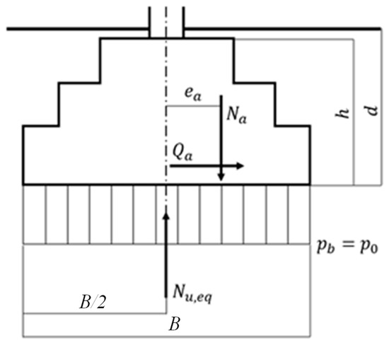
Figure 3.
Design problem in Almaty city.
Table 5.
Soil engineering properties.
The seismic reflection testing at Site A and Site B was carried out for the investigation of seismic conditions of the construction sites. It was performed with the application of two 24 channel recording systems aimed to measure reflected and refracted longitudinal and transverse seismic waves from impulse actions by impacts on the ground (i.e., 7 kg hammer blows). The testing was conducted with an arrangement of 48 geophones located at 1–2 m with excitation points located at the end points of the arrangement. The shear wave velocity profile of Site A and Site B in Almaty city is provided in Figure 4. SP RK 2.03-30-2017* provides the following equation for the determination of the average shear wave velocity to a depth of 30 m, :
where and are the thickness and velocity of the propagation of shear wave for the -th soil layer considering the total number of layers within 30 m depth.
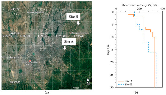
Figure 4.
Information about test sites: (a) Test site locations; (b) Shear wave velocity profiles.
- Site A
Based on the performed calculations following Equation (18), the value of for Site A equals 294 m/s. The seismic action is defined knowing that the foundation is designed in a high seismicity zone (i.e., 9 degrees of seismic intensity). Referring to Silacheva et al. [36,37], the values of peak ground acceleration with a return period of 475 years for Almaty city territory are obtained. Following the equation for statistical estimation of the undrained shear strength, , provided by Moon and Ku [35], it was calculated that equals 74.4 kPa for Site A conditions. The width of a strip foundation is assumed as 3.3 m for Site A.
Adhering to the Kazakhstani approach, the given soil of Site A corresponds to soil category II based on seismic properties (i.e., ranging between 270 m/s and 550 m/s), which assumes the seismic operational conditions’ coefficient and the decrease in the design friction angle . Considering the responsibility level of the designed structure II (normal), the reliability coefficient . The values of shape coefficients are equal to unity (i.e., ). For the given soil engineering properties of Site A, the coefficients defined in accordance with the internal friction angle are equal to 8.32, 4.17, 11.77, respectively. For 9 degrees of the seismic intensity of the selected construction site, the value of the seismicity coefficient .
Adhering to the European approach, the soil type of Site A is considered as ground type C (i.e., ranging between 180 m/s and 360 m/s) for which soil factor is assumed. Following SP RK 2.03-30-2017*, the design ground acceleration in Almaty city is for soil category II.
- Site B
Following Equation (18), the value of for the Site B equals 269 m/s. The undrained shear strength, , was calculated following Moon and Ku [35] so that of the Site B equals 59.3 kPa. The width of a strip foundation is assumed as 5 m. The assumed value of the foundation width for Site B exceeds the value for Site A due to the increased seismic intensity of the site.
Considering the Kazakhstani approach, the given soil of the Site B corresponds to soil category III based on seismic properties (i.e., is less than 270 m/s), which corresponds to the seismic operational conditions’ coefficient and the decrease in the design friction angle . For the given soil engineering properties (i.e., ), the coefficients equal 7.50, 3.62, 10.33, respectively. Similarly to Site A, the values of reliability coefficient, , shape coefficients, , and seismicity coefficient, , are taken as 1.15, 1, and 0.4, respectively.
In accordance with the European approach, the soil type of the Site B is considered as ground type C (i.e., ranging between 180 m/s and 360 m/s) for which soil factor is assumed. Following SP RK 2.03-30-2017*, the design ground acceleration in Almaty city is for soil category III.
The design response spectrum curves for various soil conditions of Site A and Site B in Almaty city are provided in Figure 5. The response spectrum function for ground type C is defined by the equations provided in EC8-1. Based on the obtained plot, it can be noticed that Site A can be characterized by higher spectral acceleration response in comparison to Site B. Thus, the soil profile of Site A is presented by stiffer soils compared to Site B soil profile.
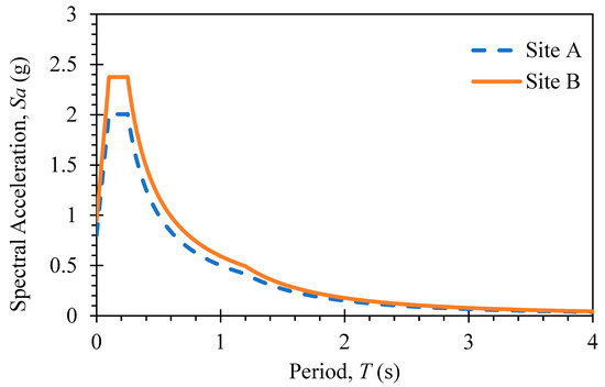
Figure 5.
Design response spectrum for Sites A and B in Almaty city.
5. Results and Discussion
A significant difference between the design procedures for verifying the seismic bearing capacity of shallow foundations adhering to the Kazakhstani and European approaches exists. Therefore, this section provides computational results for verifying the seismic bearing capacity for a strip foundation in Almaty city. Based on the performed design calculations for the determination of seismic bearing resistance of a strip foundation following SP RK 5.01-102-2013* and EC8, it was identified that the calculated results of seismic bearing resistance satisfy design requirements for both Site A and Site B.
- Site A
The Kazakhstani approach applies the design values of vertical load, horizontal load, and moment equal to 719 kN, 66 kN, and 189 kN*m, respectively. Checking the condition shows that the value of the eccentricity of the design load obtained from Equation (7) is less than . Therefore, the base of the strip foundation is fully supported by the ground. Substituting the values of soil engineering properties and coefficients of Site A into Equation (2), the ordinate of the pressure diagram . Due to , . Thus, the value of the ultimate resistance can be obtained from Equation (11):
Considering and , a condition in Equation (1) is checked:
Based on the obtained results, the seismic bearing capacity of the designed shallow foundation is ensured when adhering to the Kazakhstani approach.
For the verification of the sliding capacity of the designed foundation Equation (12) is applied:
The design condition is satisfied as the right-hand side of the equation exceeds the value of the horizontal design load. Therefore, for the given design load and foundation dimensions, the sliding does not occur.
The European approach verifies the seismic bearing capacity of a strip foundation for purely cohesive soil. The ultimate bearing capacity, , per unit length of the strip foundation defined based on Equation (16) and is equal to . The dimensionless soil inertia force is obtained considering the values of the design ground acceleration and soil factor based on Equation (17):
For sensitive clays . The values of , , and are obtained using Equation (14):
The obtained values satisfy the following constraints: , .
Substituting the obtained values into Equation (14) to check the stability:
The inequality is satisfied. The safety against seismic bearing capacity is verified when adhering to the European approach.
- Site B
The design of a strip foundation for Site B follows the same procedure as for Site A. The design values of vertical load, horizontal load, and moment of 865 kN, 66 kN, and 248 kN*m, respectively, were used to design a strip foundation for Site B conditions adhering to the Kazakhstani code of practice. Verifying the eccentricity of the design load is less than , it can be concluded that the base of the designed strip foundation is fully supported by the ground. The ordinate of the pressure diagram is defined to be equal to . Considering , the values of ordinates under the edges of the designed strip foundation are equal. Thus, the ultimate resistance can be obtained from Equation (11):
Substituting the values and into Equation (1), the safety of the designed foundation against seismic bearing capacity is verified as follows:
Thus, the Kazakhstani approach ensures the safety of the designed strip foundation against bearing capacity failure for Site B conditions.
The sliding capacity of the designed shallow foundation is checked with the help of Equation (12) as follows:
The design condition is satisfied as the right-hand side of the equation exceeds the value of the vertical design load. Therefore, for the given design load and foundation dimensions, the sliding does not occur.
According to the European approach, the ultimate bearing capacity, , per unit length of the strip foundation is calculated as . The dimensionless soil inertia force is defined based on Equation (17) as follows:
For sensitive clays . The values of , , and are obtained using Equation (15):
For the obtained values, the following constraints are satisfied: , .
Substituting the obtained values of design action effects into Equation (14), the safety against seismic bearing capacity adhering to the European approach is checked:
Therefore, the safety against seismic bearing capacity is verified following the European design approach.
However, the obtained values of the left-hand side of Equation (14) for both Site A and Site B are very close to the boundary (i.e., 0). Therefore, it can be concluded that the decided width of the designed strip foundation represents a minimum dimension when adhering to the European approach. Thus, EC8 provides a more conservative seismic design of a strip foundation than SP RK 5.01-102-2013*. Furthermore, the minimum allowable width defined by Equation (1) adhering to the Kazakhstani approach for the same loading conditions refers to 2.6 m and 4 m for Site A and Site B, respectively. Thus, the European approach provides 20–21% greater results of foundation width when designing a shallow foundation in a seismic region (i.e., for both Site A and Site B) in Kazakhstan.
The more conservative design of a strip foundation adhering to the European approach enables the design and construction of buildings and structures in seismic regions with high quality and safety levels. Moreover, the conservativeness of the European approach for the design of strip foundations over the Kazakhstani approaches is supported by the studies on comparative analysis of shallow and deep foundations in Kazakhstan [9,14,38].
6. Conclusions
The problem of earthquakes represents a significant issue for a large territory of Kazakhstan and requires to be studied carefully. The introduction of the European code of practice in Kazakhstan contributed to the need for international design methods to increase the designed buildings’ safety. Even though the design of buildings and structures adhering to the European approach has many advantages, including the increase in construction rates and cost-effectiveness, the local specialists face some difficulties associated with the complexity of understanding the new regulations. The harmonization of the national building code with Eurocode 8 requires the performance of the comparative analysis for the design of buildings and structures in seismic regions, as well as development of the National Annex considering local geological and geotechnical features.
This study presents the design procedure for verifying the seismic bearing resistance of shallow foundations when applying the national design code for the construction in seismic regions SP RK 5.01-102-2013* and EC8. The Kazakhstani code of practice has considerable differences from the Eurocode referring to the scope of application, seismic magnitude scale, classification of soil, methods for defining seismic design actions, concepts, and requirements for seismic design of buildings and structures.
The seismic design problem is presented for analyzing the bearing capacity sufficiency for the designed strip foundation at two construction sites (i.e., Site A and Site B) in Almaty city. Based on the performed comparative analysis of the considered codes of practice, significant differences between the design procedures were revealed. Referring to the performed estimations, the seismic bearing capacity is verified, adhering to Kazakhstani and European design procedures. However, a more conservative seismic design of a shallow foundation is obtained following EC8 compared to SP RK 5.01-102-2013* due to obtaining a greater margin between the results when checking the safety of the designed foundation against seismic bearing capacity. Based on the obtained results the European approach provides 20–21% greater results of foundation width when designing a shallow foundation in a seismic region in Kazakhstan.
The European standard assessed the consequences of worldwide hazards, whereas Kazakhstani design regulation refers to analyzing local earthquakes. Therefore, it can be concluded that EC8 provides more conservative results and higher safety level compared to the national code of practice. Currently, there are no reasons for the delay in transition to SP RK EN 1998-1:2004/2012 identical to EC8, which provides seismic stability at the European level for buildings constructed in seismic regions. Therefore, it can be concluded that the European approach represents a good alternative for assessing seismic hazards and geotechnical applications in Kazakhstan.
As the comparative analysis was performed on a limited number of design cases, the further analysis of designs in seismic regions adhering to the Kazakhstani and European approaches is needed to enhance the obtained results.
Author Contributions
A.Z. and S.-W.M. conceptualized the study; A.Z., J.I.O. and S.-W.M. implemented data processing under the supervision of J.K. and A.S.; the original draft of the manuscript was written by A.Z., J.I.O. and S.-W.M. with editorial contributions from J.K., A.S., Y.S. and V.K. All authors have read and agreed to the published version of the manuscript.
Funding
This research was funded by the Nazarbayev University, Collaborative Research Projects (CRPs) Grant No. 11022021CRP1508, and 11022021CRP1512.
Institutional Review Board Statement
Not applicable.
Informed Consent Statement
Not applicable.
Data Availability Statement
Not applicable.
Acknowledgments
The authors are grateful for the funding support. Any opinions, findings, conclusions, or recommendations expressed in this material are those of the author(s) and do not necessarily reflect the views of Nazarbayev University.
Conflicts of Interest
The authors declare no conflict of interest.
Nomenclature
| foundation width; | |
| foundation length; | |
| foundation depth; | |
| area of the foundation base; | |
| density; | |
| void ratio; | |
| liquidity index; | |
| average shear wave velocity to a depth of 30 m; | |
| thickness of the -th soil layer considering the total number of layers within 30 m depth; | |
| velocity of the propagation of shear wave for the -th soil layer considering the total number of layers within 30 m depth; | |
| NSPT | number of blows obtained from a standard penetration test; |
| undrained shear strength; | |
| design value of the unit weight of soil above the foundation base; | |
| design value of the unit weight of soil below the foundation base; | |
| design value of the friction angle of the bearing soil layer; | |
| cI | design value of the cohesion of the bearing soil layer; |
| vertical design eccentric load; | |
| moment acting at the foundation base. | |
| vertical component of the ultimate resistance of the foundation under seismic load; | |
| seismic operational conditions’ coefficient; | |
| reliability coefficient based on occupancy of the structure; | |
| ordinates of the diagram of the ultimate pressure under the edges of the foundation base; | |
| , , | are the coefficients of foundation shape; |
| coefficients defined by the design friction angle of the bearing soil layer; | |
| seismicity coefficient; | |
| eccentricity of the design load; | |
| eccentricity of the ultimate pressure diagram; | |
| sliding capacity of the foundation under seismic load; | |
| decrease in the design frictional angle; | |
| partial factor for the angle of shearing resistance; | |
| partial factor for the undrained shear strength; | |
| design acceleration on ground type A; | |
| agR | reference peak ground acceleration on ground type A; |
| building importance factor; | |
| soil factor; | |
| design action effects at the foundation level; | |
| ultimate bearing capacity of the foundation under a vertical centered load; | |
| dimensionless soil inertia force; | |
| model partial factor; | |
| numerical parameters depending on the soil type; | |
| partial factor for material properties; | |
| dimensionless soil inertia force; | |
| unit mass of the soil. |
References
- Khapin, A.V.; Makhiev, B.E. Evolution of seismic loads determination methods according to the codes of the Republic of Kazakhstan. Tpaдиции И Иннoвaции В Cтpoитeльcтвe И Apxитeктype Cтpoитeльcтвo 2019, 11, 109–116. [Google Scholar]
- Bespayev, A.A. About the transition from SP RK 2.03–30–2017* to design according to SP RK EN 1998-1:2004/2012. Becтник Haциoнaльнoй Инжeнepнoй Aкaдeмии Pecпyблики Kaзaxcтaн 2019, 3. [Google Scholar]
- SNiP RK B.1.2-4-98; Construction in Seismic Regions. KazNIISA: Almaty, Kazakhstan, 1998.
- Zhunusov, T.; Taubaev, A.; Itskov, I.; Mikhailova, N.; Nurmagambetov, A. Seismic Hazard and Building Vulnerability in Kazakhstan. In Seismic Hazard and Building Vulnerability in Post-Soviet Central Asian Republics; Springer: Dordrecht, The Netherlands, 1999. [Google Scholar] [CrossRef]
- SNiP RK 2.03-04-2001; Construction in Seismic Regions. KazNIISA: Astana, Kazakhstan, 2002.
- SNiP RK 2.03-30-2006; Construction in Seismic Regions. KazNIISA: Astana, Kazakhstan, 2006.
- Bisengaliyev, M.D.; Zaidemova, Z.K.; Mukhambetzhanova, K.K. Introduction of Eurocodes in the Republic of Kazakhstan. In Πepcпeктивы Coциaльнo-Экoнoмичecкoгo Paзвития Cтpaн и Peгиoнoв; Astrakhan State University of Architecture and Civil Engineering: Astrakhan, Russia, 2019; pp. 131–134. [Google Scholar]
- Saparbayev, E.Z.; Tulebekova, A.S. Features of reforming normative base of the Republic of Kazakhstan. Aктyaльныe Нayчныe Иccлeдoвaния в Coвpeмeннoм Миpe 2019, 6, 11–15. [Google Scholar]
- Zhanabayeva, A.; Sagidullina, N.; Kim, J.; Satyanaga, A.; Lee, D.; Moon, S.-W. Comparative Analysis of Kazakhstani and European Design Specifications: Raft Foundation, Pile Foundation, and Piled Raft Foundation. Appl. Sci. 2021, 11, 3099. [Google Scholar] [CrossRef]
- SP RK EN 1998-5:2004/2012; Design of Structures for Earthquake Resistance–Part 5: Foundations, Retaining Structures and Geotechnical Aspects. KazNIISA: Astana, Kazakhstan, 2016.
- National Annex to SP RK EN 1998-1:2004/2012; Design of Structures for Earthquake Resistance–Part 5: Foundations, Retaining Structures and Geotechnical Aspects. KazNIISA: Astana, Kazakhstan, 2016.
- SP RK 2.03-30-2017*; Construction in Seismic Regions. KazNIISA: Astana, Kazakhstan, 2019.
- Lambla, V. Construction sector in Kazakhstan 2019. In Market Analysis and Development Forecasts for 2019–2024; PMR Market Insight: Krakow, Poland, 2019. [Google Scholar]
- Shaldykova, A.; Moon, S.-W.; Kim, J.; Lee, D.; Ku, T.; Zhussupbekov, A. Comparative Analysis of Kazakhstani and European Approaches for the Design of Shallow Foundations. Appl. Sci. 2020, 10, 2920. [Google Scholar] [CrossRef]
- SN RK 2.03-28-2004; Scale for the Assessment of the Earthquake Intensity MSK-64 KazNIISA. KazNIISA: Astana, Kazakhstan, 2004.
- Fardis, M.; Carvalho, E.; Elnashai, A.; Faccioli, E.; Pinto, P.; Plumier, A. Designers’ Guide to Eurocode 8: Design of Structures for Earthquake Resistance; Thomas Telford: London, UK, 2005. [Google Scholar]
- Fardis, M.; Carvalho, E.; Fajfar, P.; Pecker, A. Seismic Design of Concrete Buildings to Eurocode 8; CRC Press: Boca Raton, FL, USA, 2015. [Google Scholar]
- Tiznado, J.C.; Paillao, D. Analysis of the seismic bearing capacity of shallow foundations. Revista de la Construcción 2014, 13, 40–48. [Google Scholar] [CrossRef][Green Version]
- Prakash, S.; Puri, V.K. Foundations under seismic loads. In Proceedings of the 15th European Conference on Soil Mechanics and Geotechnical Engineering; IOS Press: Amsterdam, The Netherlands, 2011; pp. 793–798. [Google Scholar]
- SP RK 5.01-103-2013; Pile Foundations. KAZGOR: Almaty, Kazakhstan, 2013.
- Orr, T. Implementing Eurocode 7 to Achieve Reliable Geotechnical Designs. In Modern Geotechnical Design Codes of Practice: Implementation, Application and Development; IOS Press: Amsterdam, The Netherlands, 2012; p. 72. [Google Scholar]
- Schuppener, B. Eurocode 7: Geotechnical Design-Part 1: General Rules-Its Implementation in the European Member States. In Proceedings of the 14th European Conference on Soil Mechanics and Geotechnical Engineering, Madrid, Spain, 24–27 September 2007. [Google Scholar]
- EN 1997-1; Eurocode 7: Geotechnical Design–Part 1: General Rules. European Committee for Standardization: Brussels, Belgium, 1997.
- Frank, R.; Bauduin, C.; Driscoll, R.; Kavvadas, M. Designers’ Guide to EN 1997-1 Eurocode 7: Geotechnical Design-General Rules; Thomas Telford: London, UK, 2004. [Google Scholar]
- EN 1998-5 Eurocode 8; Design of Structures for Earthquake Resistance–Part 5: Foundations, Retaining Structures and Geotechnical Aspects. European Committee for Standardization: Brussels, Belgium, 2004.
- Toh, J.C.W.; Pender, M.J. Design approaches and criteria for earthquake-resistant shallow foundation systems. In Soil-Foundation-Structure Interaction; Taylor & Francis Group: London, UK, 2010; pp. 173–180. [Google Scholar]
- Elghazouli, A. Seismic Design of Buildings to Eurocode 8; CRC Press: Boca Raton, FL, USA, 2016. [Google Scholar]
- NTP RK 08.05.1-2013; Design of Basements and Foundations of Buildings and Structures in Seismic Regions. KazNIISA: Astana, Kazakhstan, 2015.
- Pecker, A. Analytical formulae for the seismic bearing capacity of shallow strip foundations. In Seismic Behaviour of Ground and Geotechnical Structures; CRC Press: Boca Raton, FL, USA, 2021; pp. 261–268. [Google Scholar]
- Bisch, P.; Carvalho, E.; Degee, H.; Fajfar, P.; Fardis, M.; Franchin, P.; Kreslin, M.; Pecker, A.; Pinto, P.; Plumier, A.; et al. Eurocode 8: Seismic Design of Buildings Worked Examples; Publications Office of the European Union: Luxembourg, 2012. [Google Scholar]
- EN 1998-1; Eurocode 8: Design of Structures for Earthquake Resistance–Part 1: General Rules, Seismic Actions and Rules for Buildings. European Committee for Standardization: Brussels, Belgium, 2005.
- GOST 25100-2011 Soils; Classification. ISC: Moscow, Russia, 2013.
- GOST 5180-2015 Soils; Laboratory Methods for Determination of Physical Properties. ISC: Moscow, Russia, 2019.
- GOST 12248-2010 Soils; Laboratory Methods for Determination of Strength and Deformation Characteristics. ISC: Moscow, Russia, 2011.
- Moon, S.W.; Ku, T. Undrained shear strength in cohesive soils estimated by directional modes of in-situ shear wave velocity. Geotech. Geol. Eng. 2018, 36, 2851–2868. [Google Scholar] [CrossRef]
- Silacheva, N.V.; Kulbayeva, U.K.; Kravchenko, N.A. On the realization of seismic microzonation of Almaty (Kazakhstan) in ground accelerations based on the “continual” approach. Geod. Geodyn. 2020, 11, 56–63. [Google Scholar] [CrossRef]
- Silacheva, N.V.; Kulbayeva, U.K.; Kravchenko, N.A. Probabilistic seismic hazard assessment of Kazakhstan and Almaty city in peak ground accelerations. Geod. Geodyn. 2018, 9, 131–141. [Google Scholar] [CrossRef]
- Zhanabayeva, A.; Abdialim, S.; Satyanaga, A.; Kim, J.; Moon, S.W. Comparative analysis of international codes of practice for pile foundation design considering negative skin friction effect. Int. J. Geo-Eng. 2022, 13, 11. [Google Scholar] [CrossRef]


Disclaimer/Publisher’s Note: The statements, opinions and data contained in all publications are solely those of the individual author(s) and contributor(s) and not of MDPI and/or the editor(s). MDPI and/or the editor(s) disclaim responsibility for any injury to people or property resulting from any ideas, methods, instructions or products referred to in the content. |
© 2022 by the authors. Licensee MDPI, Basel, Switzerland. This article is an open access article distributed under the terms and conditions of the Creative Commons Attribution (CC BY) license (https://creativecommons.org/licenses/by/4.0/).